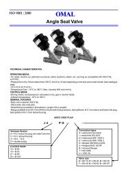
ADCA-FLT 17 HC
ADCA-FLT 17 HC
ADCA-FLT 17 HC

You also want an ePaper? Increase the reach of your titles
YUMPU automatically turns print PDFs into web optimized ePapers that Google loves.
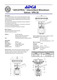
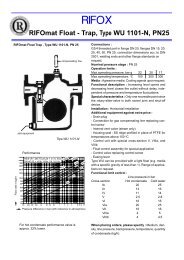
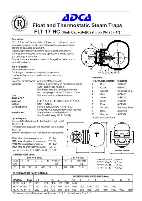
Float and Thermostatic Steam Traps<br />
<strong>FLT</strong> <strong>17</strong> <strong>HC</strong> (High Capacity)(Cast Iron DN 25 - 1”)<br />
Description<br />
<strong>FLT</strong> <strong>17</strong> float and thermostatic (integral air vent) steam traps<br />
series are designed for all types of low and high pressure steam<br />
heating and process equipment.<br />
Typical applications include unit heaters,heat exchangers,<br />
driers,jacketed vessels and all the applications where continuous<br />
drainage is essential.<br />
Connections are female screwed or flanged for horizontal or<br />
vertical installation.<br />
Main Features<br />
Modulating discharge.<br />
Discharges condensate at steam temperature.<br />
Unaffected by sudden or wide load and pressure<br />
changes.<br />
Excellent air discharge (by thermostatic air vent).<br />
Options:<br />
Internal strainer (only on horizontal models).<br />
SLR - steam lock release .<br />
Equalizing plug and venting connection<br />
and drain plug ( or blow-off valve on body).<br />
Use :<br />
Saturated and superheated steam.<br />
AVAILABLE<br />
Models :<br />
<strong>FLT</strong><strong>17</strong><strong>HC</strong>-4.5 - <strong>FLT</strong><strong>17</strong><strong>HC</strong>-10 - <strong>FLT</strong><strong>17</strong><strong>HC</strong>-14.<br />
Sizes : DN 1" - DN 25.<br />
Connections :<br />
Female screwed ISO 7/1 Rp (BS21)<br />
Flanged DIN.Special flanges upon request.<br />
Installation : Standard horizontal installation -<br />
flow from left to right <strong>FLT</strong><strong>17</strong> (L-R)<br />
Upon request:<br />
-horizontal installation with the flow from right to left<br />
<strong>FLT</strong><strong>17</strong> (R-L)<br />
-vertical installation with the flow from top to bottom<br />
<strong>FLT</strong><strong>17</strong> (V)<br />
See IMI, installation and maintenance instructions.<br />
PMA :Max.allowable pressure 16 bar<br />
TMA: Max.allowable temperature 250 o C<br />
PMO: Max.operating pressure 14 bar<br />
TMO: Max.operating temperature 198 o C<br />
How to order: i.e. <strong>FLT</strong> <strong>17</strong><strong>HC</strong> -14 DN 1” BSP.<br />
DIMENSIONS (mm)<br />
Screwed Ends DIN Flanges<br />
SIZE A B C D E WEIGHT F B WEIGHT<br />
DN Kg Kg<br />
1” 120 195 80 200 110 9 160 245 11.3<br />
Materials:<br />
Pos.NR. Designation Material<br />
1 Body GGG 40<br />
2 Cover GGG 40<br />
3 * Gasket Non asbestos<br />
4 * Seat AISI 410<br />
5 * Valve AISI 410<br />
6 * Lever AISI 304<br />
7 * Float AISI 304<br />
8 * Air Vent Stainless Steel<br />
9 Bolts Steel 8.8<br />
10 Strainer AISI 304<br />
* Available Spare Parts<br />
Max.differential pressure<br />
<strong>FLT</strong> <strong>17</strong><strong>HC</strong>- 4.5 - 4.5 bar<br />
<strong>FLT</strong> <strong>17</strong><strong>HC</strong> - 10 - 10 bar<br />
<strong>FLT</strong> <strong>17</strong><strong>HC</strong>- 14 - 14 bar<br />
FLOW RATE CAPACITY IN Kg/h<br />
DIFFERENTIAL PRESSURE (bar)<br />
MODEL SIZE 0.5 1 1.5 2 3 4.5 6 7 8 9 10 12 14<br />
<strong>FLT</strong><strong>17</strong><strong>HC</strong>-4.5 1” 900 1250 1450 <strong>17</strong>00 2010 2400<br />
<strong>FLT</strong><strong>17</strong><strong>HC</strong>-10 1” 390 550 675 790 900 1000 1200 1300 1400 1500 1590<br />
<strong>FLT</strong><strong>17</strong><strong>HC</strong>-14 1” 250 350 430 500 590 680 800 850 900 950 1000 1000 1150<br />
Recommended safety factor : continuous 1.2 - 1.5 ; discontinuous flow 2 - 3 .
abcde<br />
<strong>ADCA</strong><br />
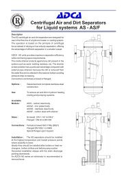
INSTALLATION AND MAINTENANCE INSTRUCTIONS<br />
FLOAT & THERMOSTATIC STEAM TRAPS<br />
INSTALLATION<br />
1. Before to install remove plastic covers placed on flanges or connection ends. The equipment<br />
has an arrow or Inlet/Outlet designations. Be sure that it will be installed on the appropriate<br />
direction.<br />
2. Install the steam trap in the point of the system, where the condensate tends to collect.<br />
It must be installed with the float lever in horizontal plane, so that it rises and falls<br />
vertically.<br />
For further maintenance information refer to IMI 1.332 E and IMI 1.335 E.<br />
Correct Installation<br />
Wrong Installation<br />
Correct Installation<br />
Wrong Installation<br />
LOSS OF GUARANTEE: Total or partial disregard of above instructions involves loss of any right to guarantee.<br />
VALSTEAM <strong>ADCA</strong><br />
We reserve the right to change the design and material of this product without notice.<br />
IMI 1.334 E 08.03