24-0276-0004
24-0276-0004
24-0276-0004

Create successful ePaper yourself
Turn your PDF publications into a flip-book with our unique Google optimized e-Paper software.
PREPARED<br />
SPECIFICALLY<br />
FOR<br />
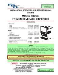
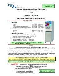
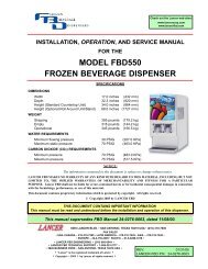
INSTALLATION, OPERATION, AND SERVICE MANUAL<br />
FOR THE<br />
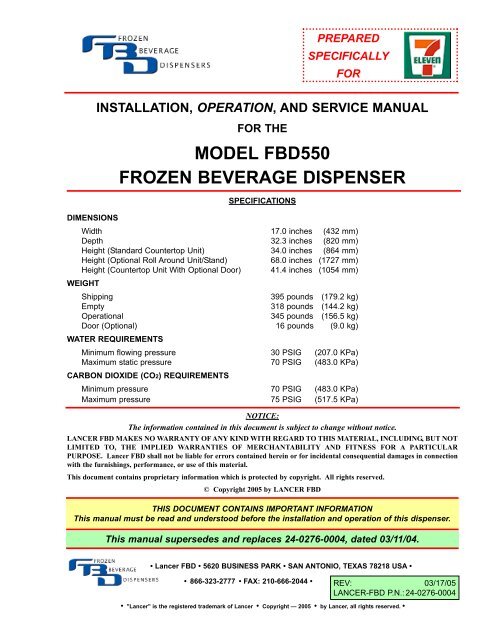
MODEL FBD550<br />
FROZEN BEVERAGE DISPENSER<br />
SPECIFICATIONS<br />
DIMENSIONS<br />
Width 17.0 inches (432 mm)<br />
Depth 32.3 inches (820 mm)<br />
Height (Standard Countertop Unit) 34.0 inches (864 mm)<br />
Height (Optional Roll Around Unit/Stand) 68.0 inches (1727 mm)<br />
Height (Countertop Unit With Optional Door) 41.4 inches (1054 mm)<br />
WEIGHT<br />
Shipping 395 pounds (179.2 kg)<br />
Empty 318 pounds (144.2 kg)<br />
Operational 345 pounds (156.5 kg)<br />
Door (Optional) 16 pounds (9.0 kg)<br />
WATER REQUIREMENTS<br />
Minimum flowing pressure 30 PSIG (207.0 KPa)<br />
Maximum static pressure 70 PSIG (483.0 KPa)<br />
CARBON DIOXIDE (CO2) REQUIREMENTS<br />
Minimum pressure 70 PSIG (483.0 KPa)<br />
Maximum pressure 75 PSIG (517.5 KPa)<br />
NOTICE:<br />
The information contained in this document is subject to change without notice.<br />
LANCER FBD MAKES NO WARRANTY OF ANY KIND WITH REGARD TO THIS MATERIAL, INCLUDING, BUT NOT<br />
LIMITED TO, THE IMPLIED WARRANTIES OF MERCHANTABILITY AND FITNESS FOR A PARTICULAR<br />
PURPOSE. Lancer FBD shall not be liable for errors contained herein or for incidental consequential damages in connection<br />
with the furnishings, performance, or use of this material.<br />
This document contains proprietary information which is protected by copyright. All rights reserved.<br />
© Copyright 2005 by LANCER FBD<br />
THIS DOCUMENT CONTAINS IMPORTANT INFORMATION<br />
This manual must be read and understood before the installation and operation of this dispenser.<br />
This manual supersedes and replaces <strong>24</strong>-<strong>0276</strong>-<strong>0004</strong>, dated 03/11/04.<br />
• Lancer FBD • 5620 BUSINESS PARK • SAN ANTONIO, TEXAS 78218 USA •<br />
• 866-323-2777 • FAX: 210-666-2044 •<br />
REV: 03/17/05<br />
LANCER-FBD P.N.: <strong>24</strong>-<strong>0276</strong>-<strong>0004</strong><br />
• "Lancer" is the registered trademark of Lancer • Copyright — 2005 • by Lancer, all rights reserved. •
TABLE OF CONTENTS<br />
SPECIFICATIONS ...................................................................................................................................COVER<br />
TABLE OF CONTENTS ......................................................................................................................................i<br />
SAFETY PRECAUTIONS ..................................................................................................................................ii<br />
1. PREPARING THE LOCATION ....................................................................................................................1<br />
1.1 LOCATION REQUIREMENTS ...........................................................................................................1<br />
1.2 ADDITIONAL REQUIREMENTS........................................................................................................1<br />
2. RECEIVING AND UNPACKING UNIT.........................................................................................................1<br />
2.1 RECEIVING........................................................................................................................................1<br />
2.2 UNPACKING ......................................................................................................................................1<br />
3. INSTALLING THE UNIT ..............................................................................................................................1<br />
3.1 FLUSH MOUNTING ...........................................................................................................................1<br />
3.2 ROLL AROUND CART.......................................................................................................................2<br />
4. CONNECTING TO ELECTRICAL POWER ................................................................................................2<br />
5. CONNECTING WATER, CO2, AND SYRUP SUPPLIES ............................................................................3<br />
5.1 WATER SUPPLY................................................................................................................................3<br />
5.2 CO2 SUPPLY......................................................................................................................................3<br />
5.3 SYRUP SUPPLY ................................................................................................................................3<br />
6. STARTING THE UNIT .................................................................................................................................4<br />
6.1 INITIAL POWER-UP...........................................................................................................................4<br />
6.2 BRIXING.............................................................................................................................................4<br />
6.3 FILLING THE CHAMBER...................................................................................................................5<br />
CRITICAL REGULATOR AND FLOW CONTROL SETTINGS .........................................................................6<br />
7. OPERATION OF THE DISPENSER............................................................................................................7<br />
7.1 OPERATING ELECTRONIC CONTROLS .........................................................................................7<br />
7.2 MACHINE ACCESS .........................................................................................................................11<br />
7.3 MACHINE SETTINGS......................................................................................................................12<br />
7.4 READOUTS......................................................................................................................................13<br />
8. CLEANING AND SANITIZING THE UNIT ................................................................................................13<br />
8.1 GENERAL INFORMATION ..............................................................................................................13<br />
8.2 REQUIRED CLEANING EQUIPMENT.............................................................................................14<br />
8.3 DAILY CLEANING OF THE UNIT ....................................................................................................14<br />
8.4 SANITIZING THE SYRUP SYSTEMS .............................................................................................14<br />
9. BASICS OF OPERATION .........................................................................................................................15<br />
9.1 MAKING ADJUSTMENTS TO THE FBD550 ...................................................................................15<br />
10. CHANGING FACTORY SET “LEVEL CONTROL” ..................................................................................16<br />
10.1 BEFORE CHANGING “LEVEL CONTROL” SETTINGS..................................................................16<br />
10.2 DRINK TOO HARD AND COLD.......................................................................................................17<br />
10.3 DRINK TOO LIQUID ........................................................................................................................17<br />
10.4 CHANGING THE DEFAULT LEVEL CONTROL SETTING .............................................................17<br />
11. CHANGING FACTORY THAW AND FREEZE SETTINGS.......................................................................18<br />
11.1 BEFORE CHANGING THAW AND FREEZE SETTINGS................................................................18<br />
11.2 CHANGING THAW AND FREEZE SETTINGS................................................................................18<br />
12. CRITICAL INFORMATION ........................................................................................................................19<br />
12.1 DEFROST AND RUN TIME DELAY.................................................................................................19<br />
12.2 CHAMBERS 90% FULL ON INITIAL SET UP .................................................................................19<br />
12.3 LINE VOLTAGE DROP ....................................................................................................................19<br />
12.4 LONG TUBING RUNS .....................................................................................................................19<br />
13. TROUBLESHOOTING GUIDE ..................................................................................................................20<br />
MECHANICAL............................................................................................................................................20<br />
ELECTRICAL .............................................................................................................................................22<br />
ELECTRONIC CONTROLS.......................................................................................................................23<br />
REFRIGERATION......................................................................................................................................<strong>24</strong><br />
DRINK QUALITY........................................................................................................................................25<br />
LCD DISPLAY ERROR MESSAGES.........................................................................................................27<br />
LCD DISPLAY MESSAGES.............................................................................................................................30<br />
LCD DISPLAY ERROR MESSAGES ..............................................................................................................31<br />
WARNING LIGHTS ..........................................................................................................................................31<br />
14. ILLUSTRATIONS, PARTS LISTINGS, AND DIAGRAMS.........................................................................32<br />
14.1 MOUNTING DIAGRAM ....................................................................................................................32<br />
14.2 FLOW DIAGRAM/SCHEMATIC .......................................................................................................33<br />
i
TABLE OF CONTENTS (CONTINUED)<br />
14.3 WIRING DIAGRAM/50-60HZ SCHEMATIC .....................................................................................34<br />
14.4 DISPENSER FRAME...............................................................................................................35-36<br />
14.5 ELECTRICAL BOX ASSEMBLY ..............................................................................................37-38<br />
14.6 COMPRESSOR AND FREEZE PAC ASSEMBLIES.....................................................................39<br />
14.7 CONDENSER COIL, FILTER AND FAN/SHROUD ASSEMBLY ..................................................40<br />
14.8 TUBE LOCATIONS .......................................................................................................................41<br />
14.9 MOTORMAN VALVE AND FACE PLATE ASSEMBLY .................................................................42<br />
14.10 MISCELLANEOUS COMPONENTS.............................................................................................43<br />
14.11 CONTROLLER BOARD ASSEMBLY............................................................................................44<br />
14.12 PRODUCT AND FAN CONNECTION .....................................................................................45-46<br />
14.13 HEADER BLOCK ASSEMBLY WITH NYLON HOSE ASSEMBLIES ...........................................47<br />
14.14 PANEL ASSEMBLIES (TOP, REAR, AND SIDES) ..................................................................49-50<br />
14.15 HEADER BLOCK SUB ASSEMBLY ........................................................................................51-52<br />
14.16 FRONT ASSEMBLY.................................................................................................................53-54<br />
14.17 DOOR ASSEMBLY AND FILTER COVER - OPTIONAL EQUIPMENT...................................55-56<br />
SAFETY PRECAUTIONS<br />
We at Lancer FBD are concerned about your safety. Please carefully read the following precautions before working<br />
with the FBD550 unit. This will familiarize you with proper equipment handling techniques.<br />
LIFTING<br />
• To avoid personal injury or damage, do not attempt to lift the unit without help. The empty unit weighs<br />
approximately 318 pounds (144.2 kg). The use of a mechanical lift is recommended.<br />
• Use gloves to protect hands from being injured by the edges of cross bracing if lifting by hand.<br />
• Use proper equipment and lifting techniques when lifting or moving equipment. The unit is top heavy.<br />
Maintain unit in a vertical, upright position when lifting and positioning the unit.<br />
ELECTRICAL<br />
• This unit must be properly electrically grounded to avoid possible fatal electrical shock or serious injury<br />
to the operator. The power cord is provided with a three prong grounded plug. If a three-hole<br />
grounded electrical outlet is not available, use an approved method to ground the unit. Only qualified<br />
electricians should perform this task and the work performed should meet all applicable codes.<br />
• Always disconnect electrical power to the unit to prevent personal injury before attempting any<br />
internal maintenance. Only qualified personnel should service internal components of electrical wiring.<br />
CARBON DIOXIDE (CO2)<br />
• CO2 (carbon dioxide) displaces oxygen. Strict attention must be observed in the prevention of CO2<br />
gas leaks in the entire CO2 and soft drink system. If a CO2 gas leak is suspected, immediately<br />
ventilate the contaminated area before attempting to repair the leak. Personnel exposed to high<br />
concentrations of CO2 gas will experience tremors which are followed rapidly by loss of consciousness<br />
and suffocation.<br />
• To avoid personal injury and/or property damage, always secure CO2 cylinders in an upright position<br />
with a safety chain to prevent cylinders from falling over. Should the valve become accidentally<br />
damaged or broken off, a CO2 cylinder can cause serious personal injury.<br />
ii
1. PREPARING THE LOCATION<br />
2 INCHES<br />
2 INCHES<br />
12 INCHES<br />
1.1 LOCATION REQUIREMENTS<br />
2 INCHES<br />
A. The operational FBD550 countertop unit<br />
weighs 345 pounds (156.5 kg) and<br />
requires a sturdy, level surface for<br />
placement. When selecting a counter<br />
location, ensure the counter will support<br />
the unit weight plus the weight of any<br />
additional equipment placed near it.<br />
B. Adequate space above and behind the unit<br />
(See Figure 1.1) is required to allow:<br />
NOTE: DOOR ASSEMBLY SHOWN AS OPTIONAL EQUIPMENT<br />
1. Removal of side panels, if service is<br />
necessary.<br />
Figure 1.1<br />
2. Air circulation around vents on sides, back, and top of unit.<br />
C. A well-ventilated room is required with a temperature of 50°F to 90°F (10°C to 32.5°C). The<br />
environment, however, should be stable and not subject to abrupt changes in temperature.<br />
D. The unit should not be exposed to direct sunlight or chemicals.<br />
1.2 ADDITIONAL REQUIREMENTS (TO BE PROVIDED BY THE CUSTOMER)<br />
A. CO2 supply with a pressure of 70 to 72 PSIG (482.6 to 496.4 KPa). If a bulk CO2 supply is<br />
used, the pressure should be set at 115 to 120 PSIG (793.5 to 828.0 KPa) and a secondary<br />
regulator installed at the unit to reduce the pressure to 70-72 PSIG.<br />
B. Syrup supply - Bag-in-Box.<br />
C. Water supply with a minimum flowing pressure of 30 PSIG (207.0 KPa) and a maximum static<br />
pressure of 70 PSIG (483.0 KPa).<br />
2. RECEIVING AND UNPACKING UNIT<br />
2.1 RECEIVING<br />
Each unit is tested and thoroughly inspected before shipment. At the time of shipment, the carrier<br />
accepts the unit and any claim for damages must be made with the carrier. Upon receiving the unit<br />
from the delivering carrier, carefully inspect carton for visible indication of damage. If damage exists,<br />
have carrier note same on bill of lading and file a claim with the carrier.<br />
2.2 UNPACKING<br />
A. Cut banding from shipping carton and remove carton by lifting up. Remove protective side<br />
panels and four corner protectors.<br />
B. Remove drip tray assembly, accessory kit and manual from top packaging. Contact the dealer<br />
if any parts are missing or damaged.<br />
C. Remove side panels from unit.<br />
D. Inspect unit for concealed damage. If evident, immediately notify delivering carrier and file a<br />
claim against same.<br />
E. Lift unit up by the frame cross bracing and remove lower portion of carton.<br />
F. Remove shipping board from bottom of unit by accessing and removing the bolts located on the<br />
underside of the shipping board.<br />
3. INSTALLING THE UNIT<br />
There are several ways to install the unit. Follow the appropriate directions for the method you are<br />
using. Insure that there is a minimum of twelve (12) inches (30.48 cm) ABOVE and two (2)<br />
inches (5.08 cm) on the SIDES and BEHIND the unit for proper ventilation.<br />
3.1 FLUSH MOUNTING<br />
Flush mounting is when the unit is mounted on a countertop. Follow the following guidelines to<br />
ensure a proper installation.<br />
A. Be sure the counter will support 345 pounds (156.5 kg) the full length of the unit (including the<br />
drip tray). If permanently mounting the unit to a countertop, use the information in Section 14.1<br />
1
to mark and drill the four (4) mounting holes in the countertop.<br />
B. With the side panels removed, lift unit by the frame cross bracing and place unit on the counter.<br />
C. If permanently mounting the unit to a countertop, install four (4) 3/8-16 UNC bolts (not included)<br />
through the underside of the counter [through the four (4) mounting holes drilled in the step just<br />
above], and into the frame.<br />
D. When the dispenser is to be permanently mounted to the counter top, seal dispenser base to<br />
counter top with a bead of clear silicone caulk or sealant which provides a smooth and easily<br />
cleaned bond to the counter.<br />
3.2 ROLL AROUND CART<br />
A roll around cart is used when a suitable countertop is not available and allows the unit to be moved<br />
for cleaning. These can be purchased from the dealer.<br />
A. Lock the wheels on the roll around cart.<br />
B. With the side panels removed, lift unit by the frame cross bracing and place the unit on the cart.<br />
C. Secure the unit to the cart by installing four (4) 3/8-16 UNC bolts (not included) through the cart<br />
mounting holes and into the frame of the unit.<br />
4. CONNECTING TO ELECTRICAL POWER<br />
<strong>24</strong>0V<br />
Ground<br />
120V<br />
120V<br />
Continuity<br />
Figure 4.1<br />
Figure 4.2<br />
Use the following guidelines to connect electrical power to the machine for both 50 and 60 Hz service.<br />
A. The machine requires single phase 230VAC. If line voltage is below 215VAC or above <strong>24</strong>5VAC,<br />
a 10% buck and boost transformer must be used. If a buck and boost transformer is installed,<br />
ensure that the boosted leg is on L1 of the contactor. Operation below 215VAC or above<br />
<strong>24</strong>5VAC may damage the unit and cause inconsistent performance. This also voids all<br />
warranties.<br />
B. If connected to a "delta" three phase electrical system, use the two low voltage legs (check each<br />
leg to ground to insure the low voltage legs are used). Using the high voltage leg will cause<br />
the machine to malfunction. In some locations, the power supply may have only one 230 volt<br />
hot leg. If so, ensure the hot leg goes to the L1 contactor in the electrical box.<br />
C. This unit will not work properly if there is more than a 10V voltage drop in the power supply line<br />
between the power source and the machine. A drop of more than 10V indicates undersized<br />
wiring or excessively long runs.<br />
D. The unit must be installed on a "single branch" circuit (on a circuit by itself), protected by 30 Amp<br />
service and a 30 Amp fuse (or circuit breaker).<br />
E. It is recommended that a 3 conductor, 30 Amp receptacle (NEMA #L-630-R) be used. Using a<br />
voltmeter, check voltage across both "hot legs" (<strong>24</strong>0VAC) and between ground and each "hot<br />
leg" (120VAC) to ensure proper wiring and voltage (see Figure 4.1).<br />
F. Remove the plug from the power cord and feed the cord through the strain relief located at the<br />
back of the unit. Tighten the strain relief securely. Reinstall the plug on the power cord and<br />
check for continuity on the plug across both "hot legs" and no continuity between each "hot leg"<br />
and ground (see Figure 4.2).<br />
G. Do not connect the unit to power at this time.<br />
2
5. CONNECTING WATER, CO2, AND SYRUP SUPPLIES<br />
5.1 WATER SUPPLY<br />
IMPORTANT<br />
A WATER PUMP AND WATER REGULATOR ARE INSTALLED IN THE BASE OF THE MACHINE.<br />
A WATER FILTER SHOULD BE INSTALLED IN THE WATER LINE BEFORE BEING<br />
CONNECTED TO THE MACHINE. FLUSH THE FILTER WITH SEVERAL GALLONS<br />
(12-15 LITERS) OF WATER PRIOR TO USE TO INSURE BLACK CARBON "FINES" ARE NOT<br />
FED INTO THE FREEZING CHAMBER.<br />
A. Fabricate a 3/8 inch supply line for connecting<br />
the unit to a potable water supply (a 3/8” barb by<br />
1/4” flare nut fitting will be required).<br />
B. Install a shutoff valve in the water line as close to<br />
the unit as practical and convenient.<br />
C. Clear the line by running a minimum of two (2)<br />
gallons (7.57 liters) of water through the line<br />
before attaching the line to the unit.<br />
D. Connect the line to the bulkhead fitting labeled<br />
"WATER IN" located at the rear of the unit (see<br />
Figure 5).<br />
E. Do not turn water on at this time.<br />
3<br />
Syrup 2<br />
Right<br />
CO2<br />
Syrup 1<br />
Left<br />
Water<br />
Figure 5<br />
5.2 CO2 SUPPLY<br />
NOTE:<br />
The CO2 supply may come from either an independent tank/regulator or a bulk CO2 system. If<br />
connected to a bulk CO2 system, install a shutoff valve and a secondary supply regulator [to be set<br />
at 70-72 PSIG (482.6-496.4 KPa)] in the line. Ensure that the CO2 line comes directly from the<br />
main branch on the bulk supply and is not branched off down line. Failure to do so may<br />
starve the unit of CO2 flow and cause performance problems.<br />
A. Fabricate a 3/8 inch supply line for connecting the unit to a CO2 supply.<br />
B. Connect the supply line to the CO2 bulkhead fitting labeled "CO2 IN" located at the rear of the<br />
unit (see Figure 5). A 3/8” barb by 1/4” flare nut fitting will be required to make connection.<br />
C. Splice a barb "cross" into the CO2 supply line and run two (2) lines to the syrup pump CO2 inlets.<br />
D. Do not turn on the CO2 at this time.<br />
5.3 SYRUP SUPPLY<br />
The unit must be connected to a BIB (Bag-in-Box). See below for the appropriate connection<br />
method.<br />
NOTE<br />
Installations requiring long runs of tubing [25 feet (7.62 meters)] may encounter pressure fluctuation<br />
problems. The machine's sensors may indicate that the machine is out of syrup, water, or CO2. To<br />
avoid pressure fluctuations, consider the following solutions.<br />
A. Increase the tubing size to 3/8 inch diameter.<br />
B. Install booster pumps in the supply lines. Use a vacuum regulating valve with syrup booster<br />
pumps.<br />
C. Increase primary CO2 regulator pressure from bulk or tank CO2 to 105 - 120 PSIG (723.9 to<br />
827.4 KPa). A secondary regulator will be necessary for syrup pumps to avoid exceeding<br />
manufacturer’s recommended operating pressures. Set the secondary regulator to 70-72 PSIG<br />
(482.6-496.4 Kpa).<br />
BIB SUPPLY<br />
A. Fabricate two (2) 1/4 inch supply lines for connecting the unit to the syrup pumps.
B. Connect the lines to the bulkhead fittings labeled "SYRUP 1 LEFT" and "SYRUP 2 RIGHT"<br />
located at the rear of the unit (see Figure 5).<br />
C. Do not turn on the CO2 at this time.<br />
6. STARTING THE UNIT<br />
Access Panel<br />
Electrical Box Cover<br />
Figure 6.1<br />
Figure 6.2<br />
6.1 INITIAL POWER-UP<br />
A. Insure the electrical power is disconnected from the unit.<br />
B. Using a Phillips head screwdriver, remove the stainless steel access panel located below the<br />
keypad (see Figure 6.1).<br />
C. Remove the splash plate and electric box cover (see Figure 6.2).<br />
D. Plug unit in to the electrical power. The graphics display should illuminate. Check for the<br />
display of information on the LCD control panel (this will read "COPYRIGHT" on bottom line of<br />
LCD display).<br />
E. With voltage meter, check voltage at contactor between L1 & L2 and record. Also check<br />
between L1 and ground bar, and between L2 and ground bar, to ensure highest voltage leg is<br />
on L1 (see Figure 6.3 and Section 14.3).<br />
F. Access the “Line Voltage” readout in the "SERVICE MENU\READOUTS\COMMON<br />
READOUTS" section of the LCD menu. If the “Readout” voltage is more than two (2) volts<br />
different than the voltage across L1 and L2, the "Voltage Offset" must be changed. Failure<br />
to do so will cause performance loss of the unit.<br />
(1) To change the "voltage offset", go to "SERVICE MENU\MACHINE SETTINGS\COMMON<br />
SETTINGS" and enter the difference between the meter reading and the “Line Voltage”<br />
readout to make the LCD voltage reading match the L1 and L2 voltage.<br />
(2) Reinstall the splash plate and electric box cover.<br />
6.2 BRIXING<br />
A. With the unit powered up, press both of<br />
the "OFF" buttons on the display to<br />
ensure the unit is in the OFF state.<br />
CAUTION<br />
CHECK ALL SUPPLY LINES TO INSURE<br />
THAT THEY ARE CONNECTED TO THE<br />
CORRECT FITTINGS. IF LINES ARE NOT<br />
CONNECTED PROPERLY, COMPONENTS<br />
WILL BE DAMAGED.<br />
B. Open the water supply valve and check<br />
all water line connections for leaks.<br />
C. Check all syrup supply connections at<br />
the rear of the machine for leaks<br />
D. Open the CO2 tank valve and adjust the<br />
primary tank regulator until the "CO2<br />
4<br />
L2<br />
L1<br />
Figure 6.3
Pressure" readout in the "SERVICE MENU\ READOUTS\ COMMON READOUTS" reads 70-72<br />
PSIG (482.6 KPa to 496.4 KPa). Check all CO2 line connections for leaks.<br />
E. Adjust the CO2 secondary regulator (located inside the machine) to read 28-32 PSIG (193.2 to<br />
220.8 KPa) according to the LCD readout found in the "REGULATED CO2" readout in the<br />
"SERVICE MENU\ READOUTS\ COMMON READOUTS" section of the LCD menu.<br />
IMPORTANT!<br />
SET ALL PRESSURES USING THE LCD READOUTS ON THE UNIT - NOT BY THE GAUGES<br />
ON THE REGULATORS!<br />
F. Close Syrup flow controls by backing (counter-clockwise) controls all the way out (see Figure<br />
6.4).<br />
G. Using water only, check the flow rate (through the sample valve) and set water flow to provide<br />
a flow of 15 ounces in 10 seconds using a graduated container. Do this for both left and right<br />
side flow controls. Turn control adjustment screw clockwise to increase flow or counter-clockwise<br />
to decrease flow.<br />
H. Pre-set Syrup flow by turning in Syrup flow controls 2 1/4 turns (clockwise).<br />
I. Place a container under the sample tube and fully depress the sample valve until a good water<br />
and syrup mixture is obtained (see Figure 6.5). This sample should be discarded.<br />
J. Place a sixteen (16) ounce (0.473 l) cup under sample tube and fully depress the sample valve<br />
until 9 - 12 ounces (0.266 - 0.355 liter) have been dispensed into cup.<br />
K. Measure the brix with a refractometer. Set brix to between 13.5 and 15.0 by adjusting the syrup<br />
brix flow controller clockwise to increase brix level or counter-clockwise to decrease brix level.<br />
If the brix requires adjustment, discard a sample before checking the brix again.<br />
NOTE<br />
Do not adjust the brix with the water flow control setting unless you are unable to obtain the<br />
desired brix with adjustments to the syrup flow control.<br />
Brix reading is affected by temperature. Samples taken from the chamber should be at the<br />
same temperature as from the sample valve.<br />
L. Repeat steps I, J, and K for other side.<br />
6.3 FILLING THE CHAMBER<br />
A. Access "CO2 SOL" by going to the "SERVICE MENU\MANUAL ON/OFF" section of the service<br />
menu.<br />
B. Displace the air in the chamber with CO2 by activating the CO2 solenoid.<br />
1. Pull and hold the relief ring until the escaping, rushing air sound almost stops; then release<br />
the ring. Allow the pressure to rebuild in the tank.<br />
2. Repeat this procedure at least two more times until the air has been displaced by the CO2.<br />
Remember to deactivate the CO2 solenoid upon completion.<br />
C. Repeat steps A and B above for right side of unit. Remember to deactivate the CO2 solenoid<br />
Sample Valve<br />
Sample<br />
Figure 6.4<br />
5<br />
Figure 6.5
upon completion.<br />
D. With CO2 in the chamber, press the left side "FILL" button to begin filling the chamber with product.<br />
If the chamber does not fill, gently pull the Relief Ring until filling begins and then release.<br />
As the chamber fills, the pressure in the chamber will increase until it rises above the PSI fill<br />
point. At this point, the chamber will stop filling and the LCD will readout "Fill Hold". It will then<br />
be necessary to pull the relief ring to relieve the pressure and allow filling to continue. Slowly<br />
pull the relief ring until the pumps activate, then release. Repeat the venting process until the<br />
chamber is 90% full (level with relief valve), then press Fill button to turn OFF.<br />
Fill one (1) chamber at a time.<br />
E. Repeat steps A, B, C, and D for the right chamber.<br />
F. Press the "DEFROST" and then the "RUN" buttons on both sides of the control panel to begin<br />
the freezing process. The beater motors will begin to run but the compressor will wait for<br />
two (2) minutes before starting. After the two (2) minute waiting period, the machine will<br />
defrost and then begin the freeze cycle.<br />
G. After an initial freeze down [approximately ten (10) to twelve (12) minutes], the product will be<br />
frozen and ready to dispense.<br />
NOTE<br />
On an initial freeze down, products must be given adequate time to absorb CO2. Until CO2 is<br />
properly and adequately absorbed, drinks could be too "wet" or too "heavy". If adjustments are<br />
necessary, refer to section 9.<br />
H. Re-check CO2, Water, and Syrup lines for leaks.<br />
CRITICAL REGULATOR AND FLOW CONTROL SETTINGS<br />
SET ALL PRESSURES USING THE LCD READOUTS ON THE UNIT - NOT BY THE GAUGES ON THE<br />
REGULATORS!<br />
CO2 PRIMARY REGULATOR<br />
The CO2 Primary Regulator MUST BE SET TO 70-72 PSIG<br />
(482.6 TO 496.4 KPa).<br />
CO2 SECONDARY REGULATOR The CO2 Secondary Regulator SHOULD BE SET AT 28-32 PSI<br />
(Secondary Regulator) (193.1 TO 220.8 KPa) STATIC PRESSURE.<br />
The CO2 Secondary Regulator is on the header assembly which is<br />
behind the access panel. This regulator is a “non-vent” regulator.<br />
This means that if you lower the regulator setting, you will need to<br />
dispense drinks (with “Fill” activated) until cylinder begins to refill<br />
before the new setting will register on the gauge.<br />
FLOW CONTROLLERS<br />
WATER FLOW MUST BE SET TO PROVIDE A FLOW OF<br />
15 OUNCES IN 10 SECONDS BEFORE ADJUSTING THE BRIX.<br />
BRIX MUST BE SET BETWEEN 13.5 - 15. Flow controllers are on<br />
the header assembly. A sample may be taken by fully depressing the<br />
sample valve while”FILL” is in the “OFF” position.<br />
6
LEFT SIDE<br />
LANCER FBD<br />
SAN ANTONIO, TEXAS<br />
RIGHT SIDE<br />
FILL BEATER RUN<br />
FILL BEATER RUN<br />
DEF.<br />
OFF<br />
DEF.<br />
OFF<br />
CANCEL<br />
BACK FWD SELECT<br />
Figure 7.1<br />
7. OPERATION OF THE DISPENSER<br />
7.1 OPERATING ELECTRONIC CONTROLS<br />
A. The electronic machine controls are designed to provide a logical sequence of operation with a<br />
minimum of written instruction. System operating parameters are selected and set from a<br />
menu.<br />
B. LEFT and RIGHT Side Buttons (see Figure 7.1).<br />
1. Each side has five (5) active buttons. They are labeled FILL, BEATER, RUN, DEF (defrost),<br />
and OFF.<br />
2. Each button operates a double acting switch. Pressing the button once activates the<br />
process. Pressing the button a second time deactivates the process. Take care not to<br />
double press the buttons when first activating a process.<br />
The RUN button initiates the freeze process. After pressing this button, the<br />
RUN beater motors will run for two minutes before the compressor starts. This<br />
delay eliminates the possibility of "short cycle" damage to the compressor.<br />
Run also maintains the flow of product into the chambers when needed.<br />
OFF<br />
The OFF button turns off all the machine's refrigeration and chamber refill<br />
systems. All of the electronic controls are still active.<br />
BEATER<br />
DEF<br />
FILL<br />
The BEATER button activates the beaters inside the freezing chambers. The<br />
beaters can be activated to mix the slurry.<br />
NOTE:<br />
The beaters start automatically when the RUN or DEF buttons are pressed.<br />
The DEF button allows the user to manually defrost chamber. Because the<br />
unit automatically defrosts during the day, it is not necessary to defrost<br />
manually. However, this button provides the option to do so if desired.<br />
NOTE:<br />
If the machine is in the "OFF" state when the DEF button is pushed, there will<br />
be a two (2) minute delay before the compressor starts.<br />
The FILL button activates the solenoid valves that allow product to flow into<br />
the freezing chambers (providing the pressure in the barrel is low enough to<br />
allow a fill). Each chamber should be filled to 90% of chamber capacity (level<br />
with the relief vent valves) prior to start-up.<br />
C. Common Controls and Displays<br />
1. The four (4) control buttons, located below the LCD display, allow access to the various<br />
menu levels for the machine (see Figure 7.1).<br />
7
CANCEL<br />
The CANCEL button cancels any current operation and steps the operator<br />
back one (1) level in the menu.<br />
BACK<br />
The BACK button steps the operator backwards within the current level. This<br />
button also allows the operator to decrease or lower values (numbers).<br />
FWD<br />
The FWD button steps the operator forward within the current level. This<br />
button also allows the operator to increase or raise values.<br />
SELECT<br />
The SELECT button allows the operator to enter changes in the unit<br />
programming and it also allows the operator to move into different levels in<br />
the menu.<br />
2. The LCD display screen in the center of the control panel allows the operator access to unit<br />
status, settings, and operational information (see Figure 7.2). The screen is divided into<br />
three (3) sections. The upper left and right portions of the screen display the current status<br />
of each chamber. The lower half of the screen displays a mode that can be changed or<br />
monitored.<br />
D. Explanation of the Menu Structure (See Figure 7.3)<br />
1. Access to the control panel is separated into two (2) levels. These levels have been<br />
established to make certain information available to the operators and other information<br />
available to service personnel.<br />
Level One<br />
This CUSTOMER MENU level is designed for the machine operator at the<br />
store level. The store operator should only access this level of information,<br />
and should NOT access or make changes in the SERVICE MENU without<br />
prior authorization and approval.<br />
Level Two The SERVICE MENU has been established for the use of authorized service<br />
technicians ONLY. This level provides access to all setup values that will<br />
optimize the operation of the machine. Incorrect settings at this level could<br />
prevent the machine from operating properly or cause damage to the unit.<br />
Included in this level are various accumulated totals and diagnostic tools that<br />
help the technician evaluate problems.<br />
NOTE<br />
To access the Service Menu, press the FWD button on the control panel until “SERVICE<br />
MENU” displays. Press the unmarked button on the right side of the panel. The service<br />
menu has been accessed when “MACHINE SETTINGS” displays. Press FWD to access<br />
other options.<br />
E. How to Access and Change Values<br />
The same procedure for changing values applies to all access levels. The following steps allow<br />
the parameters of the control system to be monitored and changed.<br />
1. The current mode is displayed in the lower half of the LCD. Press the FWD button to step<br />
to the next mode. Continue pressing the FWD or BACK button until the desired mode is<br />
displayed. When the desired mode is displayed, press SELECT to enter the mode.<br />
2. To make changes to the displayed mode, press the SELECT button. When a value in the<br />
lower half of the display begins to flash, this indicates that the value can be changed.<br />
3. To change the value, press the FWD button to increase the value or the BACK button to<br />
decrease the value. Any on/off functions can be changed by pressing the SELECT button.<br />
4. Once the desired value is displayed, press the SELECT button to enter the value into the<br />
computer. Pressing the SELECT button will stop the display from flashing. When the value<br />
8
stops flashing, it has been changed.<br />
NOTE:<br />
When entering TIME, WAKE, or SLEEP functions, both the hours and minutes must be<br />
selected before the computer will accept the change. For the Defrost Times, days in upper<br />
case (capitals) are selected. Days in lower case are NOT selected.<br />
SIDE 1 STATUS<br />
SIDE 2 STATUS<br />
MODE DISPLAY<br />
LEFT SIDE<br />
LANCER FBD<br />
SAN ANTONIO, TEXAS<br />
RIGHT SIDE<br />
FILL BEATER RUN<br />
FILL BEATER RUN<br />
DEF.<br />
OFF<br />
DEF.<br />
OFF<br />
CANCEL<br />
BACK FWD SELECT<br />
Figure 7.2<br />
NOTES<br />
9
Machine<br />
Settings ><br />
Readouts<br />
Manual<br />
On/Off<br />
Base<br />
Changes<br />
Left Side<br />
Settings ><br />
Right Side<br />
Settings ><br />
Left Side<br />
Readouts<br />
Right Side<br />
Readouts<br />
Common<br />
Readouts<br />
L CO2 Sol<br />
L Solution Sol<br />
L Beater Motor<br />
L Defrost Sol<br />
L Refrig Sol<br />
L Prod Out<br />
R CO2 Sol<br />
R Solution Sol<br />
R Beater Motor<br />
R Defrost Sol<br />
R Refrig Sol<br />
R Prod Out<br />
Compressor<br />
Fan Motor<br />
Level Control<br />
Thaw/Freeze<br />
Level Control<br />
Thaw/Freeze<br />
Customer Menu<br />
Copyright<br />
Version<br />
Time<br />
Date<br />
Fault Code<br />
History ><br />
Common<br />
Totals<br />
MaxDefTime<br />
Volt. Offset<br />
Beater %<br />
Tank Press<br />
Syr Press<br />
Return Temp<br />
Inlet Temp<br />
Liq Level<br />
Beater %<br />
Tank Press<br />
Syr Press<br />
Return Temp<br />
Inlet Temp<br />
Liq Level<br />
H2O Press<br />
CO2 Press<br />
Reg CO2 Press<br />
Line Volt<br />
Comp Hrs<br />
Comp Cycl<br />
Power On Hrs<br />
Sleep Hrs<br />
Base<br />
Thaw/Freeze<br />
Base<br />
Liquid Level<br />
Base<br />
Refrigeration<br />
Base Common<br />
Settings<br />
Left Side<br />
Thaw/Freeze<br />
Baseline<br />
Thaw Base<br />
Freeze Base<br />
FFreeze Base<br />
Cutoff LO %<br />
Current Thaw<br />
Current Freeze<br />
Current FFreeze<br />
Right Side<br />
Thaw/Freeze<br />
Baseline<br />
Thaw Base<br />
Freeze Base<br />
FFreeze Base<br />
Cutoff LO %<br />
Current Thaw<br />
Current Freeze<br />
Current FFreeze<br />
Left Side<br />
Liquid Level<br />
Full Base PSI<br />
Rfill Base PSI<br />
PressConFac<br />
Current Full<br />
Current Rfill<br />
Right Side<br />
Liquid Level<br />
Full Base PSI<br />
Rfill Base PSI<br />
PressConFac<br />
Current Full<br />
Current Rfill<br />
Left Side<br />
Duty Cycle<br />
Up to 12 Defrost<br />
Times & Day<br />
Right Side<br />
Left Side<br />
Totals<br />
Right Side<br />
Totals<br />
Defrost Cycl<br />
Sold Out Hrs<br />
Beater Hrs<br />
Run On Hrs<br />
Error Hrs<br />
Syrup Mins<br />
Defrost Cycl<br />
Sold Out Hrs<br />
Beater Hrs<br />
Run On Hrs<br />
Error Hrs<br />
Syrup Mins<br />
Left Side<br />
Up to 12 Defrost<br />
Times & Day<br />
Machine<br />
Totals<br />
Are You<br />
Sure?<br />
Day of Week<br />
Load All<br />
Defaults<br />
DL Savings<br />
Defrost Times ><br />
Wake<br />
Sleep<br />
Wake/Sleep<br />
Time ><br />
Error History 0<br />
thru 9<br />
To enter "Service Menu"<br />
press blank button on<br />
"Right Side" of keypad<br />
Service<br />
Menu<br />
Use these buttons on Keypad<br />
to navigate the Menu:<br />
One Side Min<br />
One Side Thaw<br />
One Side Max<br />
Two Side Min<br />
Two Side Thaw<br />
Two Side Max<br />
Full Freeze<br />
Delta T Min<br />
Delta T Max<br />
BACK<br />
Service Menu<br />
Common<br />
Settings ><br />
Right Side<br />
Duty Cycle<br />
H2O Reset 50<br />
H20 Out 45<br />
CO2 Reset 50<br />
CO2 Out 45<br />
L Side Sy.<br />
R Side Sy.<br />
Def Min Time<br />
Def Off Temp<br />
One Side Min<br />
One Side Thaw<br />
One Side Max<br />
Two Side Min<br />
Two Side Thaw<br />
Two Side Max<br />
Full Freeze<br />
Delta T Min<br />
Delta T Max<br />
Sy. Reset 50<br />
Sy. Out 45<br />
Sy. Reset 50<br />
Sy. Out 45<br />
LANCER FBD550 MENU<br />
SELECT<br />
CANCEL<br />
FORWARD<br />
Figure 7.3<br />
10
7.2 MACHINE ACCESS (SEE FIGURE 7.2)<br />
A. Machine Operator Display<br />
Mode Display Description Preset Value<br />
1. VERSION Shows current version of the software installed.<br />
2. TIME Used to set the time of day. The machine uses a<br />
<strong>24</strong> hour format (military time) clock. The clock has a<br />
battery backup which maintains correct time even if<br />
not plugged into electrical power.<br />
3. DATE Used to set the date and day of the week. mmm-dd dow<br />
4. DAYLIGHT Sets Daylight Savings Time (DST) option. ON for<br />
SAVINGS<br />
use of DST; OFF for use of Standard time.<br />
5. DEFROST TIMES Each side can defrost itself up to 12 times a day. 4 hours<br />
Set the defrost times so the machine does not<br />
defrost during periods of high demand.<br />
Low demand, every 3 hours. High demand, every<br />
4-5 hours. Offset Left Side and Right Side defrost<br />
times by 60 minutes.<br />
6. WAKE/SLEEP TIME Sets the machine wake and sleep times. 00:00<br />
To manually wake-up and operate the unit, press<br />
DEFROST, then RUN.<br />
7. FAULT CODE This feature stores the last 10 error codes and helps<br />
HISTORY<br />
the service agent to readily diagnose a problem.<br />
The readout is formatted as shown in the two<br />
examples below.<br />
0 : Out of syrup (first error is an out<br />
of syrup error)<br />
0S:04/03/00 12:31:05 (error started at<br />
12:31 PM on 4/3/00)<br />
0E:04/03/00 13:33:56 (error ended at<br />
1:33 PM on 4/3/00)<br />
1 : Out of CO2 (second error is an<br />
out of CO2 error)<br />
1S:04/07/00 15:03:55 (error started at<br />
3:03 PM on 4/7/00)<br />
1E:04/08/00 10:26:01 (error ended at<br />
10:26 AM on 4/8/00)<br />
The same format continues on for errors 2 through 9.<br />
8. SERVICE MENU Authorized technician access. N/A<br />
Service Note: Press “DEF” and then “RUN” on the control panel to start a machine that<br />
has been turned off manually. This allows the machine to automatically<br />
reset the baseline.<br />
11
7.3 MACHINE SETTINGS<br />
These settings are preset by the machine. DO NOT change unless there is a problem with<br />
drink quality.<br />
Mode<br />
L Side Settings Level Control = 3 The higher the value, the higher the product level<br />
in the chamber.<br />
R Side Settings<br />
The lower the value, the lower the product level in<br />
the chamber.<br />
The lower the value, the harder and colder.<br />
Thaw/Freeze = 3<br />
The higher the value, the higher the drink<br />
temperature.<br />
The lower the value, the lower the drink<br />
temperature.<br />
For more frozen, use lower values.<br />
For more liquid or less frozen, use higher values.<br />
Test for proper drink temperature (<strong>24</strong>°F to 28°F)<br />
before adjusting.<br />
Defrost Max Time Max Def Time = 360 Number of minutes “Defrost Cycle” will run unless<br />
“Return Temperature” reaches 50°F first.<br />
Common Settings Voltage Offset = 0 Use this offset to match the “Line Voltage” readout<br />
(in “Common Readouts”) to the actual incoming<br />
voltage measured with a voltmeter at L1 and L2 of<br />
the contactor.<br />
This must be completed prior to starting machine for operation.<br />
1. Measure, with a voltmeter, incoming line voltage at L1 and L2 of contactor and record.<br />
2. Read LCD “Line Voltage” reading under READOUTS - Common Readouts and compare<br />
with voltmeter reading. [If within two (2) volts, skip Steps 3 and 4.]<br />
3. Using Voltage Offset, enter valve that will allow LCD Line Voltage readout to match the<br />
voltmeter reading.<br />
4. Once this is set, the machine is ready to run.<br />
12
7.4. Readouts<br />
For information and diagnostics.<br />
Mode<br />
L Side Readouts Allows user to view Beater % = This percentage represents<br />
R Side Readouts information about frozen and thaw status.<br />
each side individually<br />
. Tank Pressure = This represents current pressure<br />
in the chamber (tank).<br />
Syrup Pressure = This represents current pressure<br />
of the syrup at the header.<br />
Return Temp. =<br />
Inlet Temp. =<br />
Liquid Level = 3<br />
This represents the current<br />
temperature of the return<br />
refrigerant line to the<br />
compressor.<br />
This represents the current<br />
temperature of the refrigerant<br />
line entering the cold pac.<br />
“Display Only” This changing<br />
value is controlled by the<br />
machine. A number above 3<br />
means the chamber level is<br />
rising and a number below 3<br />
means the chamber level is<br />
lowering.<br />
Common Readouts Allows user to view H20 Pressure = This represents the current<br />
information common<br />
incoming water pressure.<br />
to both sides.<br />
CO2 Pressure = This represents the current<br />
incoming CO2 pressure.<br />
Regulated CO2 = This represents the current<br />
internally REGULATED CO2<br />
as set by the secondary<br />
CO2 regulator.<br />
Line Voltage =<br />
This represents the current<br />
incoming line voltage.<br />
8. CLEANING AND SANITIZING THE UNIT<br />
8.1 GENERAL INFORMATION<br />
NOTE<br />
The following cleaning and sanitizing procedures pertain to the Lancer FBD equipment identified by<br />
this manual. If other equipment is being cleaned, follow the guidelines established for that<br />
equipment.<br />
A. Lancer equipment (new or reconditioned) is shipped from the factory, cleaned and sanitized in<br />
accordance with NSF guidelines. After installation is complete, the operator of the equipment<br />
must provide continuous maintenance as required by this manual and/or state and local health<br />
department guidelines to ensure proper operation and sanitation requirements are maintained.<br />
B. Cleaning and sanitizing should be accomplished only by trained personnel. Sanitary gloves are<br />
to be used during cleaning and sanitizing operations. Applicable safety precautions must be<br />
observed. Instruction warnings on the product being used must be followed.<br />
13
C. Water lines are not to be disconnected during the cleaning and sanitizing of syrup lines to avoid<br />
contamination.<br />
D. Do NOT use strong bleaches or detergents. They tend to discolor and corrode various<br />
materials.<br />
E. Do NOT use metal scrapers, sharp objects, steel wool, scouring pads, abrasives, solvents, etc.,<br />
on the dispenser.<br />
F. Do NOT use hot water above 140°F (60°C). This may damage certain materials.<br />
8.2 REQUIRED CLEANING EQUIPMENT<br />
A. A mild soap solution (for example, Ivory Liquid, Calgon, etc.) mixed with clean, potable water at<br />
a temperature of 90 to 110°F (32 to 44°C) should be used to clean the external components of<br />
the equipment. Any equivalent mild soap solution may be used as long as it provides a caustic<br />
based, non-perfumed, easily rinsed mixture containing at least two (2) percent sodium<br />
hydroxide (NaOH). Rinsing must be thorough and use clean, potable water which is also at a<br />
temperature of 90 to 110°F (32 to 44°C).<br />
B. Sanitizing solutions should be prepared in accordance with the manufacturer's written<br />
recommendations and safety guidelines. Any sanitizing solution may be used as long as it is<br />
prepared in accordance with the manufacturer's written recommendations and safety guidelines,<br />
and provides 200 parts per million (PPM) available chlorine. Sanitizing solution is to be purged<br />
from line(s) and equipment by flushing with product only until there is no after taste. Do not<br />
rinse with water.<br />
NOTE<br />
Please note that a fresh water rinse cannot follow sanitization of equipment. Purge only with the<br />
end use product until there is no after taste in the product. This is an NSF requirement.<br />
8.3 DAILY CLEANING OF THE UNIT<br />
CAUTION<br />
DO NOT USE ABRASIVE TYPE CLEANERS.<br />
A. On a daily basis, or more often if necessary, wash all exterior surfaces of unit with a mild soap<br />
solution. Rinse with clean water. Wipe dry with a clean soft cloth.<br />
B. Remove and wash drip tray in mild soap solution. Rinse with clean water. Reinstall drip tray on<br />
unit.<br />
8.4 SANITIZING THE SYRUP SYSTEMS<br />
The unit should be sanitized annually. Follow the sanitizer manufacturer’s recommendation in<br />
preparing the sanitizing solution. The following procedure takes about one (1) hour.<br />
A. Press the "OFF" button followed by the "DEF" button for both chambers. Remember, there will<br />
be a two (2) minute delay before the unit begins defrosting.<br />
B. After defrost, activate both the left and right CO2 solenoids by going to the "SERVICE MENU\<br />
MANUAL ON/OFF" section of the service menu.<br />
C. Place a container under the valve and empty the barrels. Activate the beaters to facilitate<br />
removal of product.<br />
D. Turn off the CO2 solenoids and beaters after the barrels are empty.<br />
E. Prepare five (5) gallons of sanitizing solution following manufacturer’s directions. The water<br />
temperature should be 110 to 115°F (44 to 46°C). Stir the solution until sanitizing agent has<br />
completely dissolved.<br />
F. Disconnect all BIB connectors from syrup boxes, then install BIB Adapters (Lancer PN 05-0<strong>24</strong>9)<br />
onto BIB connectors.<br />
G. Turn off the water at source, and then press down on sample valve until water is purged from<br />
system.<br />
H. Place a container under the sample valve tube and press sample valve to purge syrup and water<br />
from lines. When the Tygon BIB tubing is clear of syrup, lower sanitizing adapters into<br />
sanitizing solution. Continue purging lines until any foam in the line clears.<br />
I. Activate both the left and right solution solenoids at the "SERVICE MENU\MANUAL ON/OFF"<br />
section of the service menu.<br />
14
J. Fill each chamber approximately 2/3 full with sanitizing solution/water mixture then deactivate<br />
the solution solenoids.<br />
K. Activate both the left and right CO2 solenoids to evacuate the solution from the chambers. Once<br />
the chambers are evacuated, deactivate the CO2 solenoids and purge pressure from<br />
cylinders by pulling faceplate relief valve.<br />
L. Again, activate the solution solenoid and allow freeze chamber to fill 1/2 full of sanitizing<br />
solution. Deactivate the solution solenoid and turn on beaters. Let solution agitate for three (3)<br />
minutes.<br />
M. Activate the CO2 solenoids and evacuate the sanitizing solution from cylinder. Then turn off<br />
beater, deactivate the CO2 solenoids and purge pressure from cylinder.<br />
N. Remove sanitizing adapters from the BIB lines and reconnect the lines to the syrup supplies.<br />
O. Turn on water at source.<br />
P. Partially refill the chambers (1/3 full) with syrup and water by activating the solution solenoids.<br />
Turn off the solenoids. Run the beaters for a few seconds.<br />
Q. Drain the product by activating the CO2 solenoids.<br />
R. Partially refill the chamber again and test the product for off taste. Repeat the drain/fill process<br />
until no off taste exists.<br />
S. When there is no more off taste, fill the unit following the procedure outlined in Section 6.3.<br />
9. BASICS OF OPERATION<br />
NOTE<br />
On an initial freeze down, products must be given adequate time to stabilize. Making adjustments too<br />
quickly may negatively affect drink quality.<br />
9.1 MAKING ADJUSTMENTS TO THE FBD550<br />
A. In order to produce a consistent, quality beverage with the FBD550 Frozen Beverage Machine,<br />
there are a few critical settings that must be maintained. These settings are preset when you<br />
receive the machine from the factory, but, due to variations that occur (e.g., in operating<br />
environments, syrups, and individual machines, etc.), it may be necessary to make minor<br />
adjustments to these critical settings. Adjustments are easily made using the keypad located at<br />
the front of the machine, or by adjusting the CO2 regulator located behind the access panel<br />
below the keypad.<br />
B. The settings that control product quality and production rate are:<br />
1. Beverage Syrup Content or Brix Level (Set on Syrup Flow Control)<br />
2. Chamber “Level Control”<br />
3. Regulated CO2 Injection Pressure<br />
4. Freeze and Thaw Settings<br />
C. In Sections 6 and 7 of this manual are instructions on machine installation and initial operation.<br />
These instructions should be followed for initial setup of the machine. If the product quality is<br />
not as desired after allowing time for stabilization, the critical settings should be checked and<br />
adjusted as necessary. The following sections discuss the sequence and method to verify these<br />
settings. These four (4) critical settings are explained here to help better your<br />
understanding of how the machine operates so you can make adjustments, if necessary.<br />
1. Adjusting the Brix Level<br />
a. Consistent, high quality beverages require adjusting and maintaining the syrup content<br />
of the drink or brix level between 13.5 and 15. A brix level lower than 13.0 may cause<br />
operational problems. A low brix level (lower than 13.0) will produce a weak tasting<br />
drink and tends to freeze product around the beater shaft. A high brix level (higher than<br />
15.0) causes freezedown times to be longer and produces a more liquid drink. Water<br />
flow rate must be set to provide a flow of 15 ounces in 10 seconds prior to adjusting brix.<br />
2. “Level Control”<br />
a. The FBD550 frozen beverage dispenser utilizes a proprietary liquid level control system<br />
(patented) to hold a constant liquid level. A constant liquid level assures a quality frozen<br />
product.<br />
b. If a more “wet” product is desired, the numerical setting (0-6) should be increased. If a<br />
“drier” and colder product is desired, the numerical setting should be decreased.<br />
15
c. The default value set at the factory is 3. This setting should produce an excellent<br />
quality product. (See Section 10 for instructions on changing settings.)<br />
3. Regulated CO2 Injection Pressure<br />
a. The CO2 injection pressure is set by adjusting the secondary regulator, located behind<br />
the access panel below the control panel in the front of the machine. The CO2<br />
regulator should be set at 28-32 PSIG (206.8 to 220.8 KPa). The unit then<br />
automatically sets the chamber pressure between 25 and 30 PSIG (172.5 and 206.8<br />
KPa).<br />
NOTE<br />
Some "cola syrups" have been shown to produce a better quality drink with a lower<br />
chamber pressure. However, lowering the "Regulated CO2 regulator" will affect both<br />
chambers. For adjusting individual chamber pressures, refer to Section 10.<br />
4. Thaw and Freeze Settings<br />
a. The Thaw and Freeze settings signal the refrigeration system when to start freezing and<br />
when to stop freezing. The liquid in the chamber freezes until it reaches the desired<br />
frozen consistency; then the refrigeration system shuts off and the chamber begins to<br />
thaw. The liquid continues to thaw until it reaches a consistency specified by the Thaw<br />
value. The Thaw value is the point at which the refrigeration system turns back on and<br />
refreezes the product. This assures the product is maintained in a good acceptable<br />
quality frozen drink range.<br />
b. Prior to changing any Thaw or Freeze settings, make sure the brix and water flow rate<br />
are correct and the liquid level control settings are properly set. Also assure the<br />
chambers stay filled to the proper levels with the proper amount of CO2. The optimum<br />
frozen drink temperature is <strong>24</strong> to 28°F (-4.4 to -2.2°C) and should be checked prior<br />
to making any adjustments. (See Section 10 for instructions on changing settings.)<br />
CAUTION<br />
IF THE THAW - FREEZE IS SET AT A LOWER SETTING, COMPRESSOR “SHORT<br />
CYCLE” CAN OCCUR THAT WILL CAUSE THE COMPRESSOR TO OVERHEAT. IF A<br />
LOWER SETTING IS USED, THE DISPENSER OPERATION MUST BE MONITORED TO<br />
INSURE THE COMPRESSOR DOES NOT “SHORT CYCLE”.<br />
c. The Thaw and Freeze settings may be raised or lowered to change the temperature of<br />
the product. A default setting of 3 is set at the factory. To decrease the temperature,<br />
decrease the numerical setting to 2 or 1; to increase the temperature, increase the<br />
numerical setting to 4 or 5.<br />
10. CHANGING FACTORY SET “LEVEL CONTROL”<br />
NOTE<br />
Always check brix and water flow rates before adjusting “Level Control”.<br />
The factory setting of the liquid “Level Control” may be changed to alter the consistency of the product.<br />
Adjusting the liquid “Level Control” will change a drink that is too liquid or one that is frozen too hard.<br />
A product that is frozen too hard will not allow the chamber to stay full and the drink will dispense with<br />
sudden releases of CO2 (“spitting”). A “too full” chamber may cause a “too wet” drink.<br />
10.1 BEFORE CHANGING “LEVEL CONTROL” SETTINGS<br />
A. Each machine ships with preset level control values. These values should be correct for<br />
normal operation of the machine and should not have to be modified.<br />
B. Before making any changes to the level control settings, defrost both chambers by<br />
pressing the “DEF” buttons located on the control panel. The machine may<br />
automatically correct any problems with drink quality after going through a defrost cycle.<br />
C. After the defrost cycle, the compressor may cycle on and off several times to ensure that the<br />
product is uniformly frozen. Wait several minutes before judging the quality of the product.<br />
D. If factory level control settings are correct, the product should freeze, thaw and then refreeze to<br />
an acceptable consistency range. Remember, drinks poured directly after a freeze cycle will<br />
appear more frozen than the last drink poured before the unit begins to refreeze the cylinder.<br />
E. The level control settings of each drink chamber are preset to a default value of 3. If the<br />
16
secondary regulator inside the unit is properly set to 28-32 PSIG (206.8 to 220.8 KPa), the<br />
chamber pressure will be “set” automatically.<br />
F. After the machine is installed and each chamber is properly filled, press the “DEF” button on the<br />
control panel to allow the machine to automatically “baseline”. Baselining indicates to the<br />
machine that the chamber contains liquid. As a result, the machine sensors determine how<br />
much to freeze the product.<br />
G. The display will flash “DEFROSTING” until baselining is complete. The machine will<br />
automatically start running if the machine was running when the defrost cycle was started. If the<br />
machine was not running before the defrost cycle started, the “RUN” button must be pressed.<br />
Note that there may be a delay of up to two (2) minutes before the machine turns on after the<br />
“RUN” button is pushed. This delay is normal. Do not press the “RUN” button again or press<br />
any other buttons until the machine starts.<br />
10.2 DRINK TOO HARD AND COLD<br />
A. If the drink is too hard and cold or the chamber is not full, adjust the “level control” to a higher<br />
level setting. Use the recommended settings that follow to properly adjust the liquid level<br />
control settings.<br />
B. It will be necessary to drain off several drinks to allow the chamber to fill and rebalance. It is<br />
also then necessary to defrost the chamber and allow the product to refreeze. If the drink is still<br />
too hard, repeat the process taking the level control setting to the next higher value.<br />
10.3 DRINK TOO LIQUID<br />
A. If the drink is cold, but is still a liquid, adjust the level control to a lower level setting. Use the<br />
recommended settings that follow to properly adjust the level control.<br />
B. It will be necessary to drain off several drinks to allow the chamber to fill and rebalance. It is<br />
then necessary to defrost the chamber and allow the product to refreeze. If the drink is still too<br />
liquid, repeat the process taking the level control to the next lower setting.<br />
C. If the product is still too liquid, it may be necessary to adjust the THAW-FREEZE beater settings.<br />
Refer to Section 11 (Changing Factory Thaw and Freeze Settings).<br />
D. Drink temperature should be between <strong>24</strong>°F and 28°F (-4.4°C to -2.2°C).<br />
NOTE<br />
If "Wet" or "Dry" drinks are common to both chambers, adjust "Regulated CO2" up to lighten<br />
drink or down to make drink wetter before adjusting level controls!<br />
MORE LIQUID<br />
"DRY" OR MORE<br />
FROZEN<br />
HIGHER LEVEL SETTING<br />
HIGHER LEVEL SETTING<br />
HIGHER LEVEL SETTING<br />
FACTORY SETTING<br />
LOWER LEVEL SETTING<br />
LOWER LEVEL SETTING<br />
LOWER LEVEL SETTING<br />
6<br />
5<br />
4<br />
3<br />
2<br />
1<br />
0<br />
Recommended “Level Control” Settings<br />
Figure 10.1<br />
10.4 CHANGING THE DEFAULT LEVEL CONTROL SETTING<br />
A. The level control setting is preset at the factory at a value of 3.<br />
B. If the drink is not frozen enough, or if the drink is too hard and too cold and dispenses slowly,<br />
after the machine has been running for 10 to 15 minutes, it may be necessary to adjust the level<br />
control settings.<br />
C. To change the machine’s level control settings, access the level two service menu.<br />
1. Access the service level by pressing the “FWD” button on the control panel until the<br />
“SERVICE MENU” displays. Press the unmarked button on the right side of the panel.<br />
“Machine Settings” displays.<br />
17
2. Press the “SELECT” button, “L Side Settings” displays. If “R Side Setting” is desired, press<br />
“Forward”.<br />
3. Press “SELECT” and “Level Control” displays.<br />
4. Press the “SELECT” button and the default setting of “3” begins to flash. The level is raised<br />
by pressing the “FWD” button and lowered by pressing the “BACK” button. When the<br />
desired number is reached, press “SELECT” and the new setting stops flashing and is set<br />
into the computer.<br />
D. When settings are complete, press the "CANCEL" button until "Copyright" displays.<br />
NOTE<br />
If the machine continues to yield a drink that is too liquid or too hard after changing level control<br />
settings, it may be necessary to adjust the THAW and FREEZE settings (refer to Section 11,<br />
Changing Factory Thaw And Freeze Settings).<br />
11. CHANGING FACTORY THAW AND FREEZE SETTINGS<br />
11.1 BEFORE CHANGING THAW AND FREEZE SETTINGS<br />
A. Each machine ships with THAW and FREEZE values preset. These values should be correct<br />
for normal operation of the machine and are designed to produce a drink temperature<br />
between <strong>24</strong> and 28 degrees. Before making any changes to THAW AND FREEZE<br />
settings, check drink temperature. If drink temperature is within correct range, DO NOT<br />
CHANGE THAW-FREEZE SETTINGS.<br />
B. Before changing the THAW or FREEZE settings, verify that the level control and Brix settings<br />
are properly set. After verifying the “Level Control”, defrost both chambers by pressing the<br />
“DEF” buttons located on the control panel. The machine may correct any problems with drink<br />
quality after going through a defrost cycle.<br />
1. After the defrost and refreeze cycle, the compressor may cycle on and off several times to<br />
ensure that the product is uniformly frozen. Wait several minutes, and dispense several<br />
drinks, before judging the quality of the product.<br />
2. The product should freeze to a proper frozen texture, thaw, and refreeze to the same<br />
general texture. The compressor turns on when the thawed product requires refreezing and<br />
shuts off when the product is frozen enough.<br />
3. If the product is freezing too cold (below <strong>24</strong>°F), the THAW - FREEZE value may be<br />
increased. If the product is not cold enough (above 28°F), the THAW - FREEZE value may<br />
be decreased. Use the recommended settings that follow when making adjustments to the<br />
THAW - FREEZE value.<br />
WARMER<br />
DRINK<br />
TEMPERATURES<br />
HIGHER THAW/FREEZE SETTING<br />
HIGHER THAW/FREEZE SETTING<br />
HIGHER THAW/FREEZE SETTING<br />
FACTORY SETTING<br />
6<br />
5<br />
4<br />
3<br />
COLDER<br />
DRINK<br />
TEMPERATURES<br />
LOWER THAW/FREEZE SETTING<br />
LOWER THAW/FREEZE SETTING<br />
LOWER THAW/FREEZE SETTING<br />
Recommended THAW-FREEZE Settings<br />
Figure 11.1<br />
11.2 CHANGING THAW AND FREEZE SETTINGS<br />
The THAW-FREEZE values should only be changed if the drink quality is not as expected. Use the<br />
following steps to change THAW-FREEZE settings as necessary. Before changing the<br />
THAW-FREEZE settings, verify that the brix and level control settings (see Section 10.1) are<br />
properly set. THAW-FREEZE settings may not need changing if corrections are made to the level<br />
control settings.<br />
18<br />
2<br />
1<br />
0
A. Changing the THAW-FREEZE for LEFT SIDE and RIGHT SIDE<br />
1. Access the service level by pressing the “FWD” button on the control panel until the<br />
“SERVICE MENU” displays. Press the unmarked button on the right side of the panel,<br />
“MACHINE SETTINGS” displays.<br />
2. Press “SELECT” and “L SIDE SETTINGS” displays.<br />
3. Press “SELECT” and “LEVEL CONTROL” displays.<br />
4. Press the “FWD” button until “THAW-FREEZE” displays.<br />
5. To change the THAW-FREEZE values, press “SELECT” and the number starts to flash.<br />
6. Press “FWD” to change to a higher setting or press the “BACK” button to change to a lower<br />
setting.<br />
7. Once the desired setting displays, press “SELECT” to save the new value.<br />
8. Press “CANCEL” and “L SIDE SETTING” displays.<br />
9. To change the other chamber settings, press “FWD” until “R SIDE SETTINGS” displays.<br />
Repeat Steps 3-7 above.<br />
10. When settings are complete, press the “CANCEL” button until “Copyright” displays.<br />
12. CRITICAL INFORMATION<br />
The following information is critical to proper machine operation. Prior to troubleshooting problems with<br />
the unit, review the following information.<br />
12.1 DEFROST AND RUN TIME DELAY<br />
When either the RUN or the DEF button on the control panel is pressed, the message<br />
“RUN BEATER” or “DEF BEATER” is displayed. This is a time delay before the compressor starts<br />
running. The delay can be as long as two (2) minutes before the unit starts running or defrosting.<br />
Do not press the buttons again. Wait, and the machine will start defrosting, then freezing.<br />
12.2 CHAMBERS 90% FULL ON INITIAL SET UP<br />
Before beginning a RUN-FREEZE cycle, the chambers should be filled approximately 90% full (up<br />
to relief valve). If the chambers are above the 90%level, with Fill Off, open the dispensing valve and<br />
allow a small amount of liquid to drain out. If the chambers are not 90% full, press “OFF”, then<br />
“FILL”, and then slowly pull the vent ring on the faceplate to vent gas, and allow liquid to fill. The<br />
screen will display “Filling”. Fill slowly and do NOT let the pressure drop more than three to four<br />
(3-4) PSI.<br />
12.3 LINE VOLTAGE DROP<br />
The unit requires a separate electrical circuit complete with a 30 AMP breaker or fuse on a 30 AMP<br />
service. The unit will not function properly if the line voltage drops more than 10 volts between the<br />
power source and the machine.<br />
12.4 LONG TUBING RUNS<br />
A. Long runs of supply tubing can cause problems if the pressure drop (between the CO2 tank or<br />
syrup source and the unit) is too much. Runs longer than 25 feet (7.62 m) will require special<br />
attention. The machine’s sensors may indicate that the machine is out of syrup, water, or CO2.<br />
Consider the following solutions:<br />
1. Increase the tubing size from 3/8 inch diameter to 1/2 inch diameter.<br />
2. Install booster pumps in the supply lines. Use a vacuum regulating valve with syrup<br />
booster pumps.<br />
3. Increase primary CO2 regulator pressure from bulk or tank CO2 to 105 - 120 PSIG (723.9 to<br />
827.4 KPa). A secondary regulator will be necessary for pumps (syrup, water) to avoid<br />
exceeding manufacturer’s recommended operating pressures.<br />
19
13. TROUBLESHOOTING GUIDE<br />
The following information is a listing of the most common problems that could keep the FBD550<br />
Dispenser from operating properly. Contact the factory for details, when necessary.<br />
MECHANICAL<br />
TROUBLE CAUSE REMEDY<br />
13.1 Chamber will not fill. A. “Fill” off. A. Press “Fill” button. “Filling” or<br />
“Fill Hold” will appear on LCD<br />
display.<br />
B. Pressure in chamber above B. Gently pull faceplate relief valve<br />
“RFill” (refill) point.<br />
ring to relieve pressure in chamber.<br />
C. “Defrosting” or “Sleeping”. C. Press “Def”, then “Run”. Wait for<br />
unit to freeze and red light to go<br />
out.<br />
D. Out of CO2, Syrup or Water. D. Check LCD messages for<br />
"Out of ……." condition.<br />
E. Tank Pressure readout not E. Observe "Tank Transducer" in<br />
moving between 18 and<br />
"Readouts". Check transducer and<br />
40 psi or doesn’t lower when replace if necessary.<br />
chamber pressure is reduced.<br />
F. Solution or CO2 solenoid F. In “Manual On/Off, energize<br />
valve won’t open.<br />
solenoid and check for <strong>24</strong>VAC at<br />
coil. Clean or replace solenoid if<br />
necessary<br />
G. Relay board not sending G. Test solenoid relay on relay board<br />
power to solenoid coils.<br />
for <strong>24</strong>VAC output and 5VDC input.<br />
Replace Relay Board, if necessary.<br />
H. Lower Board problem. H. Test Lower Board for +5, +15, and<br />
–15 outputs at J-5 plug (see<br />
Figure 14.3). Replace Lower<br />
Board, if necessary.<br />
I. 192 VA Transformer problem. I. Test transformer for 220VAC input.<br />
Also check for <strong>24</strong>VAC and 12VAC<br />
output (see Figure 14.3). Replace<br />
transformer if necessary.<br />
13.2 Chamber fills even A. Solution solenoid plunger A. In “Manual On/Off”, energize<br />
when turned off. sticking. solenoid and check for <strong>24</strong>VAC at<br />
coil. Clean or replace solenoid, if<br />
necessary.<br />
B. Solution solenoid energized. B. Test solenoid relay on relay board<br />
for <strong>24</strong>VAC output and 5VDC relay<br />
coil input. Replace Relay Board, if<br />
necessary.<br />
C. Solution solenoid left “ON” C. In “Manual On/Off”, turn solenoid<br />
in “Manual”.<br />
off.<br />
13.3 Out of Product A. Unit receiving no water, syrup A. Assure water is on and CO2 supply<br />
displayed (Out of and/or CO2. is not empty or turned off. Also<br />
Water, Syrup or CO2).<br />
check to see that syrup container<br />
is not empty and is hooked up.<br />
B. Restriction in lines. B. Assure all lines are free of crimps<br />
or restrictions.<br />
C. Regulator pressures (unit C. Check pressure readouts (H2O,<br />
(Item 13.3 continued on next page.)<br />
and syrup pumps) too low.<br />
CO2 and Syrups) for 70-72psi.<br />
Adjust regulators, if necessary.<br />
D. Syrup or Water Pump failure. D. Check all pumps and replace, if<br />
necessary.<br />
20
TROUBLE CAUSE REMEDY<br />
(Item 13.3 continued from previous page.)<br />
E. CO2 or water can’t keep up E. Reroute water or CO2 lines to<br />
with unit demand.<br />
maximize supply pressure. Install<br />
Water Booster if necessary.<br />
F. Excessive pressure drops F. Observe “Syrup Press” readouts<br />
in syrup lines.<br />
as chamber fills to verify. Increase<br />
line diameter or relocate syrup<br />
source closer to unit. Syrup<br />
pressures may only be raised (by<br />
increasing pump CO2 pressure)<br />
if separate regulators are installed<br />
for unit and syrup pumps. Never<br />
exceed pump manufacturer’s<br />
recommended maximum CO2 inlet<br />
pressure. (see Section 12.4).<br />
H. Transducer problem (H2O, H. Check pressure readouts (H2O,<br />
CO2 or Syrup).<br />
CO2 and Syrup) for 70-72psi. If not<br />
within 2psi, adjust regulator and/or<br />
check transducer. Replace<br />
transducer, if necessary.<br />
I. Lower Board problem I. Test lower board for +5, +15, and<br />
–15 outputs at J-5 plug (see<br />
Figure 14.3).<br />
J. Upper Board Problem J. Circuits within Main Control (Upper)<br />
Board electronics read transducer<br />
pressures. Replace Main Control<br />
(Upper) Board, if necessary<br />
13.4 Product does not flow A. Faulty CO2 check valve. A. Inspect CO2 check valve. Clean or<br />
freely or does not flow<br />
replace.<br />
at all from dispensing B. CO2 solenoid valve won’t B. In “Manual On/Off, energize<br />
valve. open. solenoid and check for <strong>24</strong>VAC at<br />
coil. Clean or replace solenoid, if<br />
necessary.<br />
C. Solution solenoid valve C. In “Manual On/Off”, energize<br />
won’t open.<br />
solenoid and check for <strong>24</strong>VAC at<br />
coil. Clean or replace solenoid, if<br />
necessary.<br />
D. Ice particles in dispensing D. Run defrost cycle. If necessary,<br />
valve.<br />
open and close dispensing valve<br />
several times or run warm water<br />
over valve.<br />
E. Product in cylinder is frozen E. 1. Check water/syrup flow<br />
too hard or solid.<br />
rates and brix. Adjust, if<br />
necessary (see Section 6.2).<br />
2. Check Level Control setting.<br />
Adjust if necessary (see<br />
Section 10).<br />
3. Check Thaw/Freeze settings.<br />
Adjust if necessary (see<br />
Section 11).<br />
4. Defrost chamber. Assure<br />
chamber is filled to 90%, then<br />
press "Run".<br />
13.5 Product leaking from A. Beater drive seal is worn or A. Replace with new seal.<br />
rear of cold pack.<br />
damaged.<br />
B. Beater drive coupling is worn. B. Replace coupling.<br />
C. Seal is not positioned C. From inside chamber, reseat seal,<br />
correctly.<br />
making sure it is flush with back of<br />
chamber.<br />
21
13.6 Brix sample valve A. Damaged or failed o-rings A. Turn off CO2, water and disconnect<br />
leaks. on valve. syrup. Depressurize by pressing<br />
sample valve. Remove C-clip from<br />
bottom of sample valve. Remove<br />
sample valve shaft, change o-rings<br />
and reinstall.<br />
B. Inside hole of plastic header B. Replace upper header block.<br />
block is scratched or<br />
damaged.<br />
13.7 Low water pressure or A. Water not turned on or line A. Turn on water. Check for line<br />
no water pressure. restriction. restrictions.<br />
B. CO2 not turned on or too low. B. Assure CO2 is turned on and verify<br />
"CO2 Press" readout is 70-72 PSIG<br />
(482.6-496.4 KPa).<br />
C. Water pressure transducer C. Verify "H2O Pressure" readout at<br />
failure.<br />
70-72 psi. Check transducer and<br />
replace, if needed.<br />
D. Water pump failure. D. Check water pump and replace, if<br />
necessary.<br />
13.8 Noisy condenser fan. A. Fan contacting condenser, A. Remove fan guard and adjust fan<br />
fan blade guard, or other<br />
up or down as required. Remove<br />
part.<br />
obstruction as necessary. Reinstall<br />
fan guard.<br />
B. Fan blade not balanced. B. Remove fan guard, slide fan blade<br />
weights (on 3 blades) to balance<br />
fan. Replace fan, if necessary.<br />
Reinstall fan guard.<br />
C. Loose fan bracket fasteners. C. Tighten loose fasteners.<br />
ELECTRICAL<br />
TROUBLE CAUSE REMEDY<br />
13.9 Solenoids not A. Solenoid plunger not lifting. A. In “Manual On/Off”, energize<br />
activating.<br />
solenoid on and off checking for<br />
plunger movement and <strong>24</strong>VAC at<br />
coil. Clean or replace solenoid, if<br />
necessary.<br />
B. Relay Board failure. B. Test solenoid relay on Relay Board<br />
for <strong>24</strong>VAC output and 5VDC input.<br />
Replace, if necessary.<br />
C. Connectors not plugged in C. Assure connections are clean and<br />
at board or solenoid.<br />
secure at P14 and solenoid coils.<br />
13.10 Solenoids continuously A. Solenoid plunger not dropping. A. In “Manual On/Off”, energize<br />
activated.<br />
solenoid on and off checking for<br />
plunger movement and <strong>24</strong>VAC at<br />
coil. Clean or replace solenoid, if<br />
necessary.<br />
B. Solenoid Relay stuck. B. Test solenoid relay on Relay Board<br />
for <strong>24</strong>VAC output and 5VDC relay<br />
coil input. Replace, if necessary.<br />
C. Transducer failure. C. Observe "Tank Pressure" readouts<br />
and check corresponding<br />
transducer. Replace transducer, if<br />
necessary.<br />
13.11 Line voltage low A. Low voltage to unit (below A. Check voltage at L1 & L2 of<br />
on LCD. 215 volts). contactor and at wall receptacle.<br />
Install Buck/Boost transformer, if<br />
necessary (see Section 4).<br />
B. Incorrect voltage offset. B. Access “Machine Settings” menu<br />
and adjust voltage offset so "Line<br />
Voltage" readout equals L1 and<br />
L2 contactor voltage. (see<br />
Section 7.3).<br />
(Item 13.11 continued on next page.)<br />
22
TROUBLE CAUSE REMEDY<br />
(Item 13.11 continued from previous page.)<br />
C. Voltage Offset transformer C. Check Voltage Offset Transformer<br />
problem.<br />
for 220 VAC input/ <strong>24</strong> VAC output.<br />
Also check P-18 on upper board for<br />
<strong>24</strong>VAC. Replace transformer,<br />
if necessary.<br />
13.12 Low beater counts. A. Chamber is frozen too hard A. Verify correct brix, Level Control<br />
or solid.<br />
and Thaw/Freeze settings. Defrost<br />
chamber, refill to 90% and refreeze.<br />
(see Sections 9.1, 10 and 11).<br />
B. Lower motor control board B. Replace board.<br />
failure.<br />
C. Beater motor capacitor. C. Check motor capacitor and replace,<br />
if necessary.<br />
D. Beater motor problem. D. Replace beater motor.<br />
13.13 Excessively rapid A. Lower Board problem. A. Replace lower board.<br />
rising/falling beater B. Buck/Boost transformer B. Disconnect and replace<br />
counts. problem (if used). Buck/Boost transformer.<br />
13.14 Ammonia smell in A. Start capacitor has failed. A. Verify blown capacitor. Replace<br />
electrical box.<br />
start capacitor and check start<br />
relay. Replace if necessary.<br />
13.15 Fan motor not running. A. Unit in "Defrost" cycle. A. Check fan after completion of<br />
defrost cycle.<br />
B. Failed compressor or fan B. Test compressor or fan relays on<br />
relay on relay board.<br />
Relay Board for <strong>24</strong>VAC output and<br />
5VDC input. Replace Relay Board,<br />
if necessary.<br />
C. Lower motor control board C. Replace lower board.<br />
failure.<br />
D. Contactor not engaging. D. Check for <strong>24</strong> volt at coil and<br />
220 volt at T1 and T2. Replace<br />
contactor, if necessary.<br />
E. Bad fan motor. E. Replace fan motor.<br />
ELECTRONIC CONTROLS<br />
13.16 LCD readout garbled A. Voltage spike or noise. A. Press “CANCEL” several times.<br />
or blank. B. Low or no voltage to unit or B. Check L1 & L2 of contactor for<br />
loss of 5VDC signal.<br />
220 VAC and pins 1 and 2 of<br />
J5 plug on lower board for +5 VDC.<br />
Install Buck/Boost transformer or<br />
replace lower board, if necessary.<br />
13.17 One or more keypad A. Cable connecting Main A. Check for loose or incorrect<br />
buttons will not Control (upper) board to connections.<br />
function.<br />
keypad not connected<br />
properly.<br />
B. Faulty control cable. B. Replace keypad.<br />
13.18 Clock shows incorrect A. Initial setting incorrect. A. Change clock settings as described<br />
time/date.<br />
in Section 7.2 of this manual.<br />
B. Clock battery failure. B. Replace clock battery on upper<br />
board.<br />
13.19 Faulty tank pressure A. Pressure transducer failure. A. Check transducer and replace, if<br />
reading on LCD.<br />
necessary.<br />
B. Possible short in wiring from B. Clean and dry both ends of cable,<br />
transducer to PC board.<br />
and check for loose connections.<br />
C. Poor contact within connector. C. Reposition or replace transducer.<br />
D. Low 15VDC from Lower Board. D. Check for 15VDC at P17 pin 5.<br />
Replace lower board, if necessary.<br />
E. Upper board failure. E. Replace main control (Upper)<br />
board.<br />
23
REFRIGERATION<br />
TROUBLE CAUSE REMEDY<br />
13.20 Compressor won't A. Incorrect start procedure. A. Press “Def”, then “Run” to start.<br />
start. B. In 2 min., compressor delay. B. “Run Beater” or “Def Beater”<br />
indicates delay mode<br />
C. Out of CO2, Syrup or Water. C. Check pressure readouts for<br />
70-72 psi, adjust regulators,<br />
if necessary.<br />
D. Start capacitor or relay D. Test start capacitor and start relay.<br />
problem.<br />
Replace, if necessary.<br />
E. Contactor failure. E. 1. In Manual On/Off, activate<br />
“Compressor” . DO NOT RUN<br />
COMPRESSOR FOR MORE<br />
THAN 10 SECONDS! If<br />
contactor energizes, quickly<br />
check voltage across contactor<br />
T1 and T2 for 220 volt. If no<br />
voltage reading, replace<br />
contactor. "<br />
2. In Manual On/Off, activate<br />
“Compressor”. DO NOT RUN<br />
COMPRESSOR FOR MORE<br />
THAN 10 SECONDS! If<br />
contactor does not energize,<br />
quickly check voltage across<br />
contactor coil terminals for<br />
<strong>24</strong>VAC. If voltage is present,<br />
replace contactor.<br />
F. Relay board not sending F. Test relay board for <strong>24</strong>VAC output<br />
power to contactor coil.<br />
and 5VDC input on contactor relay.<br />
Replace relay board, if necessary.<br />
G. Lower Board problem. G. Test lower board for +5, +15, and<br />
–15 outputs at J-5 plug (see<br />
Figure 14.3).<br />
H. 192 VA Transformer problem. H. Test transformer for 220VAC input<br />
and <strong>24</strong>VAC and 12VAC output<br />
(see Figure 14.3).<br />
I. Compressor failure, or I. Wait for compressor to cool.<br />
overheated.<br />
Check amperage draw (normal<br />
running 13 amps) on compressor.<br />
Check compressor wiring and<br />
terminals. Replace compressor,<br />
if necessary.<br />
13.21 Compressor runs long A. Return temperature not A. Verify that Return Temperature<br />
time but won’t freeze dropping. drops below 20°F. Return<br />
down. Temperature should achieve 20°F<br />
within 7 to 25 minutes of startup<br />
(no drinks dispensed).<br />
B. Airflow through condenser B. Clear condenser of blockage.<br />
is blocked. Dirty filter.<br />
Clean air filter.<br />
(Item 13.21 continued on next page.)<br />
Contact Lancer Warranty Dept. before tapping system if unit is under warranty!<br />
C. Hot gas valve is activated C. Select "Defrost Sol" in<br />
in Manual On/Off<br />
“Manual ON/OFF”; test solenoid,<br />
then turn off.<br />
D. Base refrigeration settings. D. Load all Defaults to ensure factory<br />
settings.<br />
E. Hot gas valve is stuck open, E. Recover refrigerant and remove<br />
or debris is preventing valve<br />
from closing.<br />
blockage or replace valve, if<br />
necessary. Recharge system with<br />
48.5 oz. of R404-A.<br />
<strong>24</strong>
(Item 13.21 continued from previous page.)<br />
F. Expansion valve not opening. F. 1. Test expansion valve coil to<br />
ensure it is receiving <strong>24</strong>VAC.<br />
Replace expansion valve if<br />
plunger inside doesn't move.<br />
Contact Lancer Warranty<br />
Dept. before tapping system<br />
if unit is under warranty!<br />
Recover refrigerant and replace<br />
valve. Recharge system with<br />
48.5 oz. of R404-A.<br />
2. Test relay board for <strong>24</strong>VAC<br />
output and 5VDC relay coil<br />
input. Replace, if necessary.<br />
G. Expansion valve restriction. G. Contact Lancer Warranty Dept.<br />
before tapping system if unit is<br />
under warranty! Recover<br />
refrigerant and remove blockage or<br />
replace valve if necessary.<br />
Recharge system with 48.5 oz. of<br />
R404-A.<br />
H. Refrigeration leak or low H. Contact Lancer Warranty Dept.<br />
refrigerant charge.<br />
before tapping system if unit is<br />
under warranty! Put gages on<br />
system and check pressures.<br />
Single side suction should be<br />
32-35 psi, dual side 42-45 psi.<br />
Single and dual side discharge<br />
should be 275-300 psi. Check for<br />
and repair leaks, recharge system<br />
with 48.5 oz. of R404-A.<br />
CAUTION<br />
DO NOT PRESSURIZE LOW SIDE (EVAPORATOR AND COMPRESSOR SUCTION) ABOVE 150 PSI<br />
FOR ANY REASON! COMPONENTS WILL FAIL AND WARRANTIES WILL BE VOID.<br />
13.22 High head/suction A. Condensor air flow restricted. A. Check for air flow restriction, clean<br />
pressure. Contact<br />
condensor and air filter.<br />
Lancer Warranty Dept. B. Compressor damage B. Check amp draw on compressor<br />
before tapping system<br />
(normal running 13 amps).<br />
if unit is under C. High ambient temperature. C. Temperature surrounding unit<br />
warranty!<br />
should be less than 90°F.<br />
13.23 Low head/suction A. Low refrigerant level. A. See item 13.21.H above.<br />
pressure. Contact<br />
Lancer Warranty Dept. B. Compressor damage. B. Check amp draw on compressor<br />
before tapping system<br />
(normal running 13 amps).<br />
if unit is under<br />
warranty!<br />
DRINK QUALITY<br />
TROUBLE CAUSE REMEDY<br />
13.<strong>24</strong> Drink too “Wet” or A. Chamber not filled properly. A. Defrost, then assure chamber is<br />
“Liquid”.<br />
90% full.<br />
B. CO2 check valve clogged. B. Clean or replace check valve.<br />
C. CO2 solenoid not opening. C. Activate "CO2 Sol" in<br />
“Manual On/Off”. Check for <strong>24</strong>VAC<br />
at coil. Clean solenoid or replace,<br />
if necessary.<br />
D. CO2 level in drink too low. D. 1. To affect BOTH chambers,<br />
raise "Reg.CO2" within 28-32<br />
psi range.<br />
(Item 13.<strong>24</strong> continued on next page.)<br />
25
TROUBLE CAUSE REMEDY<br />
(Item 13.<strong>24</strong> continued from previous page.)<br />
2. To affect ONE chamber, lower<br />
the level control settings using<br />
the instructions in Section 10.2<br />
of this manual<br />
E. Secondary CO2 regulator E. Check Secondary Regulator.<br />
malfunctioning.<br />
Repair or replace secondary<br />
regulator if necessary.<br />
F. Reg'd CO2 Transducer F. Check "Reg'd CO2" in readouts,<br />
malfunctioning.<br />
compare with regulator gauge.<br />
Test transducer, replace if<br />
necessary.<br />
G. Incorrect Brix or water/syrup G. Check water and syrup flows and<br />
flow rates.<br />
adjust if necessary. Then check<br />
brix (see Section 6.2).<br />
H. Tank Pressure readout not H. Observe Tank Transducer, check<br />
moving between 18 and<br />
and replace, if necessary.<br />
40 psi or doesn’t lower when<br />
chamber pressure is reduced.<br />
I. Relay board not sending I. Test relay board for <strong>24</strong>VAC output<br />
power to CO2 solenoid coil. and 5VDC input on solenoid relay.<br />
Replace Relay Board, if necessary.<br />
J. “THAW/FREEZE” settings J. Lower the “THAW/FREEZE”<br />
are set too high.<br />
settings, using the instructions in<br />
Section 11.2, this manual.<br />
K. CO2 orifice is blocked. K. Remove blockage.<br />
13.25 Drink quality is too A. Chamber not filled properly. A. Defrost and assure chamber is<br />
light.<br />
90% full.<br />
B. Incorrect Brix or water/syrup B. Check water and syrup flows and<br />
flow rates.<br />
adjust if necessary. Then check<br />
brix (see Section 6.2).<br />
C. CO2 level in drink too high. C. 1. To affect BOTH chambers,<br />
lower "Reg.CO2" within<br />
28-32 psi range.<br />
2. To affect ONE chamber, raise<br />
the level control settings using<br />
the instructions in Section 10.2<br />
of this manual<br />
D. Secondary Regulator D. Pressure rising out of 28-32 psi<br />
pressure rise.<br />
range. Repair or replace the<br />
secondary regulator if necessary.<br />
E. “THAW/FREEZE” settings E. Raise the “THAW/FREEZE”<br />
set too low.<br />
settings using the instructions in<br />
Section 11.2 of this manual.<br />
F. Solution Solenoid F. Activate "Solution Sol" in Manual<br />
malfunctioning and not<br />
On/Off. Check for <strong>24</strong>VAC at coil.<br />
allowing the chamber to fill. Clean solenoid or replace, if<br />
necessary.<br />
G. Relay board not sending G. Test relay board for <strong>24</strong>VAC output<br />
power to solution solenoid and 5VDC input on solenoid relay.<br />
coil.<br />
Replace Relay Board, if necessary.<br />
13.26 Drinks “collapse” A. Chamber not filled properly. A. Defrost and assure chamber is<br />
or “fall”. (CO2 is<br />
90% full. Then press "Run".<br />
escaping from B. CO2 level in drink too high. B. 1. To affect BOTH chambers,<br />
the drink.)<br />
lower "Reg.CO2" within<br />
28-32 psi range.<br />
2. To affect ONE chamber, raise<br />
the level control settings (using<br />
the instructions in Section 10.2<br />
of this manual).<br />
(Item 13.26 continued on next page.)<br />
26
TROUBLE CAUSE REMEDY<br />
(Item 13.26 continued from previous page.)<br />
C. “THAW/FREEZE” settings A. Raise the “THAW/FREEZE” using<br />
are set too low. the instructions in Section 11.2.<br />
D. Air not cleared from chamber D. Follow "Filling the chamber"<br />
prior to filling chamber. instructions in Section 6.3.<br />
E. Contaminated Syrup supply. E. Syrup being used is more than<br />
three (3) months old, or is not an<br />
FCB syrup.<br />
F. Contaminants in product from F. Flush chamber and remove excess<br />
excessive lubrication of valve lubrication contaminants.<br />
or seal.<br />
G. Contaminated CO2 or water G. Contact CO2 supplier or plumber.<br />
supply.<br />
13.27 Drink tends to “grow” A. “THAW/FREEZE” settings are A. Lower the “THAW/FREEZE”<br />
or continue to expand set too high. settings using the instructions in<br />
in volume after drawn<br />
Section 11.2, this manual.<br />
into cup. B. Incorrect Brix or water/syrup B. Check water and syrup flows and<br />
flow rates.<br />
adjust if necessary. Then check<br />
brix (see Section 6.2).<br />
LCD DISPLAY ERROR MESSAGES<br />
C. CO2 level in drink too high. C. 1. To affect BOTH chambers,<br />
lower "Reg.CO2" within<br />
28-32 psi range.<br />
2. To affect ONE chamber, raise<br />
the level control settings using<br />
the instructions in Section 10.2<br />
of this manual.<br />
13.28 PMAX A. Chamber pressure above A. Dispense one (1) drink; see if<br />
55 psi. PMAX recurs.<br />
B. Expansion tank pressure B. Replace expansion tank regulator.<br />
system not working properly.<br />
NOTE:<br />
This is NOT the same regulator<br />
as used on the header.<br />
C. Tank transducer shorted C. Replace transducer.<br />
at 99 psi.<br />
D. Level Control set too high. D. Level Control settings may need to<br />
be lowered. Set the Level Control<br />
using the instructions in<br />
Section 10.2 of this manual.<br />
E. Level Control too low. E. Level Control settings may need to<br />
be raised due to excessive CO2 in<br />
the chamber. Raise the Level<br />
Control settings using the<br />
instructions in Section 10.2 of<br />
this manual.<br />
F. "Regulated CO2" transducer F. Insure that the tank transducers<br />
reading inaccurately.<br />
are reading the CO2 regulated<br />
pressure correctly [i.e., filling about<br />
5-7 PSIG (34.5-48.3 KPa) below<br />
“REG CO2”].<br />
G. Secondary regulator G. Insure CO2 regulator has not<br />
pressure creeping up.<br />
climbed above preset<br />
30-32 PSIG (206.8-220.8 KPa).<br />
H. CO2 check valve problem. H. Inspect CO2 check valve. Clean<br />
or replace if necessary.<br />
13.29 Max Fill A. Secondary CO2 pressure is A. Check Secondary CO2 for correct<br />
set above 40 psi. setting of 28-32 psi (193.1-220.8<br />
KPa).<br />
(Item 13.29 continued on next page.)<br />
27
TROUBLE CAUSE REMEDY<br />
(Item 13.29 continued from previous page.)<br />
B. Secondary regulator B. Insure CO2 regulator has not<br />
pressure creeping up.<br />
climbed above 32 PSIG Clean<br />
or repair or replace regulator, if<br />
necessary.<br />
13.30 DefPRESmax A. Tank pressure above 55 psi. A. See 13.29.<br />
13.31 DefProdOut A. Product supply is out during A. Replenish product supply<br />
defrost stage.<br />
(i.e., water, CO2, syrup).<br />
13.32 BTR-LO-ERR A. Product freezing too hard. A. 1. Check brix and correct, if<br />
Beater % below 450.<br />
necessary.<br />
2. Check Level Control and<br />
correct, if necessary.<br />
3. Check for restriction of beater<br />
blades.<br />
4. Check for failed beater motor.<br />
B. Bad capacitor on motor. B. Check capacitor and replace as<br />
required.<br />
C. Motor control board failure. C. 1. Check connector from Beater<br />
Motor to lower control board.<br />
2. Change lower control board if<br />
necessary.<br />
13.33 Syrup Out A. Unit receiving no syrup. A. Check to see that syrup container<br />
is not empty and is hooked up.<br />
B. Restriction in lines. B. Assure all lines are free of crimps<br />
or restrictions.<br />
C. Regulator pressures (unit C. Check Syrups pressure readouts<br />
and syrup pumps) too low. for 70-72psi. Adjust regulators, if<br />
necessary.<br />
D. Syrup Pump failure. D. Check pump and replace,<br />
if necessary.<br />
E. Excessive pressure drops E. Observe “Syrup Press” readouts<br />
in syrup lines.<br />
as chamber fills to verify. Increase<br />
line diameter or relocate syrup<br />
source closer to unit. Syrup<br />
pressures may only be raised (by<br />
increasing pump CO2 pressure) if<br />
separate regulators are installed for<br />
unit and syrup pumps. Never<br />
exceed pump manufacturer’s<br />
recommended maximum CO2 inlet<br />
pressure (see Section 12.4).<br />
F. Syrup Transducer problem. F. Check syrup pressure readouts<br />
for 70-72psi. If not within 2psi,<br />
adjust regulator and/or check<br />
transducer. Replace transducer, if<br />
necessary.<br />
G. Lower Board problem. G Test lower board for +5, +15, and<br />
–15 outputs at J-5 plug (see<br />
Figure 14.3).<br />
H. Upper Board Problem. H. Circuits within Main Control (Upper)<br />
Board electronics read transducer<br />
pressures. Replace Main Control<br />
(Upper) Board, if necessary<br />
13.34 H20 Out A. Unit receiving no water. A. Assure water is turned on.<br />
B. Restriction in lines. B. Assure all lines are free of crimps<br />
or restrictions.<br />
(Item 13.29 continued on next page.)<br />
28
TROUBLE CAUSE REMEDY<br />
(Item 13.29 continued from previous page.)<br />
C. Regulator pressures (unit C. Check pressure readouts (H2O and<br />
water pump) too low or CO2 CO2) for 70-72psi. Adjust<br />
out.<br />
regulators, if necessary. Replenish<br />
CO2 supply.<br />
D. Water Pump failure. D. Check pump and replace, if<br />
necessary.<br />
E. Water pressure too low, E. Reroute water to maximize supply<br />
can’t keep up with unit<br />
pressure. Install Water Booster, if<br />
demand.<br />
necessary.<br />
F. Water Transducer problem. F. Check water pressure readout for<br />
70-72psi. If not within 2psi, adjust<br />
regulator and/or check transducer.<br />
Replace transducer, if necessary.<br />
G. Lower Board problem. G. Test lower board for +5, +15, and<br />
–15 outputs at J-5 plug (see<br />
Figure 14.3).<br />
H. Upper Board Problem. H. Circuits within Main Control (Upper)<br />
Board electronics read transducer<br />
pressures. Replace Main Control<br />
(Upper) Board, if necessary<br />
13.35 CO2 Out A. Unit receiving no CO2. A. Assure CO2 supply is not empty or<br />
turned off.<br />
B. Restriction in lines. B. Assure all lines are free of crimps<br />
or restrictions.<br />
C. Regulator pressures (to unit C. Check pressure readout ( CO2) for<br />
and syrup pumps) too low. 70-72psi. Adjust regulators, if<br />
necessary.<br />
D. CO2 can’t keep up with D. Reroute CO2 lines to maximize<br />
unit demand.<br />
supply pressure or supply unit<br />
dedicated CO2 source. Bulk<br />
regulator must be 105 psi<br />
minimum, CO2 line must be tied to<br />
main branch of bulk system, with<br />
step down regulator (set 70-72psi)<br />
between tie-in and unit<br />
E. CO2 Transducer problem. E. Check CO2 pressure readout for<br />
70-72psi. If not within 2psi, adjust<br />
regulator and/or check transducer.<br />
Replace transducer, if necessary.<br />
F. Lower Board problem. F. Test lower board for +5, +15, and<br />
–15 outputs at J-5 plug (see<br />
Figure 14.3).<br />
G. Upper Board Problem. G. Circuits within Main Control (Upper)<br />
Board electronics read transducer<br />
pressures. Replace Main Control<br />
(Upper) Board, if necessary<br />
13.36 RtnTempErr A. Temperature Sensor error A. 1. Check for short in sensor and<br />
or failure.<br />
cable. LED on Main Control<br />
board goes bright if short<br />
occurs, goes out if open circuit<br />
and stays dim if working<br />
properly.<br />
2. Check for poor connection in<br />
sensor plug.<br />
3. Replace temperature sensor.<br />
29
TROUBLE CAUSE REMEDY<br />
13.38 InletTempErr A. Temperature Sensor error A. 1. Check for short in sensor and<br />
or failure.<br />
cable. LED on Main Control<br />
board goes bright if short<br />
occurs, goes out if open circuit<br />
and stays dim if working<br />
properly.<br />
2. Check for poor connection in<br />
sensor plug.<br />
3. Replace temperature sensor.<br />
MESSAGE<br />
Sleeping<br />
Cmpr StDly<br />
Cmpr Start<br />
Cmpr Run<br />
DEFWait<br />
DEFBeater<br />
DEF Cmp Wt<br />
Defrosting<br />
DEFSuspnd<br />
Run Off<br />
Run HotGasW<br />
Run Cmp Wt<br />
Run Frz Wt<br />
Run Freeze<br />
Run Thaw W<br />
Run Thaw<br />
Run Beater<br />
Fill Off<br />
L Fill Hld<br />
Fill Hold<br />
Fl Pre CO2<br />
Fl CO2 SOL<br />
L Filling<br />
Filling<br />
LCD DISPLAY MESSAGES<br />
LANCER FBD550 FROZEN BEVERAGE DISPENSER<br />
DESCRIPTION<br />
Unit in “Sleep” mode. Unit is shut down.<br />
This delay is before compressor starts. The time period varies from 1 to 30 seconds.<br />
This is displayed when compressor starts freezing or defrosting.<br />
This is displayed only on Left Side, when compressor is running on either side.<br />
This side is waiting to defrost.<br />
If “DEF” is pressed and if the beater has not been running, then this is displayed for a maximum<br />
time delay of two (2) minutes.<br />
Time delay prior to opening the Defrost Solenoid.<br />
This is displayed when side is DEFROSTING.<br />
This is displayed when a side has been interrupted by the other side freezing. After the other side<br />
has frozen down, then defrost is resumed.<br />
This is displayed when freeze is off or when the side is turned off.<br />
This is displayed on the opposite side when a side has defrosted and is waiting to refreeze or when<br />
one side is defrosting and the other side is in Run Thaw Mode.<br />
This is displayed, prior to starting a freeze down; this is a time delay before the Refrigeration<br />
Solenoid opens.<br />
This is displayed after the freeze down has finished.<br />
This is displayed when a side is freezing down.<br />
This is displayed after the Thaw percent has been reached.<br />
This is displayed when a side is Thawing before refreezing.<br />
If “Run” is pressed and if the beater has not been running then this is displayed for a maximum<br />
time delay of two (2) minutes.<br />
The unit will not fill with product when this is displayed.<br />
This is displayed during first freeze and defrost only. The pressure in the chamber has not dropped<br />
below the fill pressure.<br />
This is displayed during normal operations when the pressure in the chamber has not dropped<br />
below the fill pressure.<br />
This is displayed prior to filling the chamber with solution. This only allows CO2 into the chamber<br />
for a specified time period.<br />
This is displayed prior to filling the chamber with solution. This only allows CO2 and solution to fill<br />
the chamber until four (4) PSI is reached in the chamber.<br />
This is displayed during first freeze and defrost only. The unit is filling the chamber.<br />
This is displayed during normal operations when the chamber is filling.<br />
30
LCD DISPLAY ERROR MESSAGES<br />
LANCER FBD550 FROZEN BEVERAGE DISPENSER<br />
MESSAGE<br />
DESCRIPTION<br />
DEFPresMax Chamber pressure is above 55 PSIG during defrost only.<br />
DEFProdOut Product is out during defrost only.<br />
BTR-LO-ERR Low beater percent. Below 450%.<br />
BTR-HI-ERR High beater percent. Above 1200%.<br />
SYRUP OUT Syrup pressure is below 45 PSIG.<br />
H2OOUT Water pressure is below 45 PSIG.<br />
CO2OUT CO2 pressure is below 45 PSIG.<br />
PRESMAX Chamber pressure is above 55 PSIG during normal operations only.<br />
RunProdOut Product out during normal operations.<br />
RtnTempErr High return temperature detected or temperature sensor broken (-40). Unit still functions.<br />
Max Fill Regulated CO2 pressure is at or above 40 PSIG limit.<br />
TankPsi=0 Filling has been on for five (5) seconds and chamber pressure equals to zero (0).<br />
SFillError Filling on for four (4) minutes but chamber pressure between one (1) PSIG and fill PSIG.<br />
Product Out Product out when side is off.<br />
InletTempErr High return temperature detected or temperature sensor broken (-40). Unit still functions.<br />
This error will occur during the DEFROST CYCLE.<br />
Cmp ran too The compressor has run for more than one hour straight. Check the air filter or the<br />
long OFF refrigeration charge.<br />
HOT PRODUCT This means the product in the barrel is getting hot. A bad return temperature sensor<br />
SHUT DOWN may also be at fault.<br />
Stop BTR Long The beater shuts off after 3 hours of a PMAX error. It will restart automatically when<br />
PMAX<br />
the error is cleared.<br />
Stop BTR The beater shuts off after 3 hours of a sold-out condition. It will restart automatically when<br />
LongPrd Out the sold-out has been cleared.<br />
WARNING LIGHTS<br />
LANCER FBD550 FROZEN BEVERAGE DISPENSER<br />
PROBLEM CAUSE SOLUTION<br />
Left red light Left side - out of syrup. Replace empty syrup container<br />
flashing. (Left Side flavor), see Section 13.29.<br />
Right red light Right side - out of syrup. Replace empty syrup container<br />
flashing. (Right Side flavor), see Section 13.29.<br />
Both red lights Out of CO2. Replace empty CO2 tank.<br />
flashing. Out of Water (H2O). Check Water (H2O) Supply.<br />
Left red light on Unit defrosting If on defrost during peak draw, cancel<br />
(not flashing). (Left Side of unit). defrost by pushing “DEF” button, then<br />
push“RUN”.<br />
Right red light on Unit defrosting If on defrost during peak draw, cancel<br />
(not flashing). (Right Side of unit). defrost by pushing “DEF” button, then<br />
push“RUN”.<br />
Red lights on, but Unit in “Sleep” mode or Restart unit by pushing “DEF” button,<br />
beaters not turning. turned off. then “RUN” button on both sides.<br />
No lights, unit Check to make sure power Plug unit in and/or reset circuit breaker.<br />
not running. cord is plugged in. Check Then restart unit by pushing “DEF”<br />
to see if circuit breaker has button, then “RUN” button on both<br />
been tripped.<br />
sides of unit.<br />
31
14. ILLUSTRATIONS, PART LISTINGS, AND DIAGRAMS<br />
14.1 MOUNTING DIAGRAM<br />
This Figure illustrates the locations of threaded mounting holes in the base of the FBD550 machine.<br />
20"<br />
EDGE OF MACHINE<br />
EDGE OF<br />
MACHINE<br />
32.3"<br />
14 7/8" 1 1/16"<br />
USE 1/2" DRILL<br />
BIT (4 HOLES)<br />
10 1/4"<br />
MACHINE MUST<br />
BE SUPPORTED TO<br />
THIS POINT<br />
17"<br />
32
14.2 FLOW DIAGRAM/SCHEMATIC<br />
SYRUP<br />
IN<br />
H2O<br />
IN<br />
CO2<br />
IN<br />
H2O<br />
IN<br />
SYRUP<br />
IN<br />
A<br />
P<br />
P<br />
P<br />
P<br />
BRIX ADJUSTER<br />
CO2<br />
REG<br />
BRIX ADJUSTER<br />
P<br />
S<br />
S<br />
P<br />
S<br />
0.25<br />
0.039<br />
A<br />
0.25<br />
0.039<br />
S<br />
P<br />
CO2 INJECT<br />
CO2 INJECT<br />
EXPANSION<br />
CHAMBER<br />
CO2<br />
REG<br />
EXPANSION<br />
CHAMBER<br />
(PRESET,<br />
RELIEVING)<br />
FREEZE<br />
CHAMBER<br />
FREEZE<br />
CHAMBER<br />
L SIDE<br />
R SIDE<br />
PRODUCT DISPENSER<br />
PRODUCT DISPENSER<br />
LEGEND<br />
L<br />
E<br />
S<br />
CHECK<br />
VALVE<br />
SOLENOID<br />
G<br />
VALVE<br />
N<br />
D<br />
P<br />
CO2<br />
REG<br />
PRESSURE<br />
TRANSDUCER<br />
CO2<br />
REGULATOR<br />
33
14.3 WIRING DIAGRAM/50-60HZ SCHEMATIC<br />
WHT<br />
GRN<br />
MAIN CONTROLLER BOARD<br />
SPARE<br />
REG CO2<br />
NO SYRUP<br />
#2<br />
TANK 2<br />
PRESSURE<br />
NO CO2<br />
TANK 1 NO WATER<br />
PRESSURE<br />
NO SYRUP<br />
#1<br />
P5<br />
1 2 3 4 5 6 7 8<br />
P20<br />
P10 P11 P12<br />
P9<br />
P7 P8<br />
P18 P6<br />
P17<br />
P16<br />
3 4 5<br />
1 2 3 4 5 1 2 3 4 5 1 2 3 4 5 1 2 3 4 5 1 2 3 4 5 1 2<br />
1 2 3 4 5 1 2 3 4 5<br />
12 3 456 7 8 123 4 5 6 7 8 910<br />
3 45<br />
12<br />
RED<br />
CLR<br />
BLK<br />
WHT<br />
GRN<br />
RED<br />
CLR<br />
BLK<br />
WHT<br />
GRN<br />
RED<br />
CLR<br />
BLK<br />
WHT<br />
GRN<br />
RED<br />
CLR<br />
BLK<br />
WHT<br />
GRN<br />
RED<br />
CLR<br />
BLK<br />
WHT<br />
GRN<br />
RED<br />
CLR<br />
BLK<br />
WHT<br />
GRN<br />
RED<br />
CLR<br />
BLK<br />
WHT<br />
GRN<br />
RED<br />
WHT<br />
GRN<br />
YEL<br />
ORG<br />
BLU<br />
BRN<br />
RED<br />
BLK<br />
BLK<br />
RED<br />
BLK<br />
JUMPER<br />
CONFIGURATION<br />
P20 PINS 2 & 3<br />
WHT<br />
WHT<br />
RED<br />
GRN<br />
BLK<br />
WHT<br />
RED<br />
GRN<br />
BLK<br />
WHT<br />
RED<br />
GRN<br />
BLK<br />
WHT<br />
RED<br />
GRN<br />
BLK<br />
WHT<br />
RED<br />
GRN<br />
BLK<br />
WHT<br />
RED<br />
GRN<br />
BLK<br />
WHT<br />
RED<br />
GRN<br />
BLK<br />
R<br />
PRESSURE<br />
TRANSDUCERS<br />
RIGHT OUT<br />
OF LIGHT<br />
RT<br />
RTRN<br />
LT<br />
EXP<br />
RT<br />
RTRN<br />
RT<br />
EXP<br />
TEMPERATURE SENSOR<br />
BLK<br />
WHT<br />
LEGEND<br />
R<br />
LEFT OUT<br />
OF LIGHT<br />
FERRITE BEAD<br />
RVXXX VARISTOR<br />
CAPACITOR<br />
SOLENOID<br />
BEATER<br />
MOTOR #2<br />
RIGHT<br />
YEL<br />
RED<br />
BLU<br />
BLK<br />
GRN/YEL<br />
BLK/YEL<br />
TRANSFORMER<br />
(T1)<br />
TB - 1<br />
BROTHER MOTOR - 4uF<br />
2.5 AMP<br />
SLO<br />
ORG<br />
ORG<br />
GRN<br />
RED<br />
GRN<br />
RED<br />
BRN<br />
<strong>24</strong> VAC<br />
OUTPUT<br />
4<br />
3<br />
FUSE<br />
RV390<br />
YEL<br />
RED<br />
1<br />
2<br />
3<br />
4<br />
5<br />
6<br />
7<br />
8<br />
9<br />
GRN<br />
GRN<br />
GRN<br />
GRN<br />
GRN<br />
GRN<br />
GRN<br />
R RED LIGHT<br />
BUTT SPLICE<br />
BEATER<br />
MOTOR #1<br />
LEFT<br />
BLU<br />
BLK<br />
GRN/YEL<br />
BLK/YEL<br />
BROTHER MOTOR - 4uF<br />
RED<br />
RED<br />
2.5 AMP<br />
SLO RED<br />
<strong>24</strong>0 VAC<br />
INPUT<br />
2<br />
1<br />
GRN<br />
BLK<br />
RED<br />
RV390<br />
WHT<br />
BLK<br />
RED<br />
RED<br />
WHT<br />
RED<br />
RV390<br />
WHT<br />
BLK<br />
BLK<br />
L1 L2<br />
WHT<br />
YEL<br />
ORG<br />
BLU<br />
BRN<br />
CONTACTOR<br />
(K2)<br />
T1 T2<br />
J3<br />
BLU<br />
WHT<br />
BLK<br />
1 3 5 7 9<br />
J1<br />
1<br />
RV390<br />
G<br />
J2<br />
RED<br />
BLK<br />
2<br />
RV39<br />
2 4 6 8 10<br />
WHT<br />
3<br />
RED<br />
BLK<br />
BLK<br />
BLK<br />
4<br />
BLK<br />
WHT<br />
ORG<br />
RED<br />
5<br />
2 Amp<br />
WHT<br />
BRN<br />
6<br />
BRN<br />
BLK<br />
1<br />
BLK<br />
ORG<br />
YEL<br />
+5VDC<br />
+5VDC<br />
-15VDC<br />
RED<br />
WHT<br />
RED<br />
2<br />
3<br />
POWER BOARD<br />
RUN CAP (C1)<br />
4<br />
GRN<br />
+15VDC<br />
BLK<br />
5<br />
<strong>24</strong> VAC<br />
12 VAC<br />
G<br />
BLK GRN<br />
370V,60HZ-(35uF)<br />
370V,50HZ-(40uF)<br />
BLU<br />
6<br />
GRN<br />
5<br />
1<br />
GRN<br />
WHT<br />
RED<br />
7<br />
8<br />
G<br />
BLK<br />
RED<br />
J4 FROM GROUND (J5-P7 & 8)<br />
J5<br />
VOLTAGE READINGS ON BOARD ARE<br />
6<br />
2<br />
START CAP (C2)<br />
250V,60HZ-(145-174uF)<br />
330V,50HZ-(216-259uF)<br />
BLK BLK BLK<br />
RED<br />
WHT<br />
BLK<br />
1<br />
2<br />
3<br />
4<br />
5<br />
6<br />
1<br />
2<br />
3<br />
4<br />
5<br />
6<br />
7<br />
8<br />
RV390<br />
7<br />
3<br />
RED<br />
4<br />
8 WHT<br />
192 VA TRANSFORMER (T2)<br />
ELECTRICAL BOX ENCLOSURE<br />
P15<br />
P14<br />
123 4 5 123 4 5<br />
YEL<br />
WHT<br />
GRY<br />
PUR<br />
BLU<br />
YEL<br />
ORG<br />
RED<br />
BRN<br />
BLK<br />
CO2 #2<br />
CO2 #1<br />
REFRIG #2<br />
YEL<br />
REFRIG #1<br />
RED<br />
WHT<br />
YEL<br />
YEL<br />
BRN<br />
YEL<br />
BLU<br />
RV39<br />
RV39 RV39<br />
RV39<br />
DEF #2<br />
DEF #1<br />
YEL YEL GRY<br />
PUR<br />
SOLUTION SOLUTION<br />
#1<br />
#2<br />
BLK YEL<br />
ORG<br />
YEL<br />
RV39<br />
RV39<br />
RV39<br />
RV39<br />
BLK<br />
WHT<br />
GRN<br />
L2<br />
L1<br />
GND<br />
POWER INPUT<br />
215 - <strong>24</strong>5 VAC<br />
60 - 50 HZ<br />
14-16 RUN AMPS<br />
USED ON 50<br />
CYCLE UNITS ONLY<br />
TO L1 ON<br />
CONTACTOR<br />
TO L2 ON<br />
CONTACTOR<br />
BLK ORG<br />
BLK BRN<br />
COMPRESSOR<br />
HEATER<br />
WHT<br />
RED<br />
2 AMP<br />
GRN<br />
GROUND SECURED<br />
TO DOOR<br />
BLK<br />
WHT<br />
BLU<br />
BALLAST<br />
115<br />
BLU<br />
RED<br />
RED<br />
LAMP<br />
RED<br />
BLK<br />
BLU<br />
5<br />
R<br />
COMP<br />
START<br />
RELAY<br />
C S<br />
COMP<br />
1 2<br />
BLK<br />
GRN/YEL GRN<br />
BRN BLK<br />
BLK<br />
BLU ORG<br />
34
WHITE BLACK<br />
GREEN<br />
DETAIL “A”<br />
PLUG WIRING DETAIL<br />
18<br />
17 (SEE DETAIL “B”)<br />
16<br />
14<br />
13<br />
15 (SEE DETAIL “A”)<br />
11<br />
12<br />
1<br />
10<br />
7<br />
8<br />
9<br />
6<br />
5<br />
17<br />
DETAIL “B”<br />
ELECTRICAL<br />
BOX GROUND<br />
13<br />
3<br />
4<br />
FRAME GROUND POINT:<br />
CHECK GROUND PIN TO FRAME<br />
2<br />
14.4 DISPENSER FRAME<br />
35
14.4 DISPENSER FRAME (CONTINUED)<br />
ITEM PART NO. DESCRIPTION QTY<br />
R 1 17-2386-0001 Weldment, FBD550, 1<br />
Frame Assy<br />
R 2 12-0536-0008 Water Pump/ 1<br />
Regulator Assy,<br />
Active Charge<br />
R 3 18-0612-0002 3/8” Oetiker Clamp 1<br />
R 4 18-0612-0001 1/4” Oetiker Clamp 1<br />
R 5 17-<strong>24</strong>99-0001 Cover, Raised 1<br />
Electrical Box,<br />
FBD550<br />
R 6 18-0100-0002 Screw, #10 - 32 x 2<br />
1/4, PHP, SS<br />
R 7 <strong>24</strong>-0100-0011 Label, Bulkhead 1<br />
Diagram<br />
R 8 22-0566-0002 Fitting, Bulkhead 5<br />
1/4 Flare x 3/8” Barb<br />
R 9 18-0482-0001 Washer, 7/16, 5<br />
Internal Tooth<br />
R 10 22-0566-0001 Fitting, Bulkhead 5<br />
1/4 Flare x 1/4” Barb<br />
R 11 14-0103-0001 Clamp, Romex 1<br />
R 12 18-0100-0001 Screw, #10 - 32 x 1/2, 2<br />
PHP<br />
R 13 18-0481-0001 Washer, #10, Star 3<br />
R 14 19-2000-0001 Bracket, Shurflo 1<br />
HDA Pump<br />
R 15 14-0108-0002 Plug, NEMA, L6309 1<br />
R 16 12-<strong>0276</strong>-0002 Electrical Box Assy, 1<br />
60HZ, FBD550<br />
R 17 18-0503-0001 Nut, #10 - 32, Flange 4<br />
R 18 17-2500-0001 Bracket, Raised 1<br />
Electrical Box,<br />
FBD550<br />
R in margin indicates new or revised item<br />
36
14.5 ELECTRICAL BOX ASSEMBLY<br />
23<br />
<strong>24</strong><br />
16,13,3<br />
9<br />
10<br />
7<br />
22<br />
19<br />
20<br />
12<br />
11<br />
8<br />
21<br />
18,11,17,3<br />
15,13<br />
14<br />
13,3<br />
1<br />
2<br />
3<br />
4<br />
FOAM TAPE<br />
5<br />
FOAM TAPE<br />
6<br />
37
14.5 ELECTRICAL BOX ASSEMBLY (CONTINUED)<br />
ITEM PART NO. DESCRIPTION QTY<br />
R 1 17-0401-<strong>0004</strong> Generic Electrical 1<br />
Enclosure<br />
R 2 18-2139-0001 Screw, 8 - 32 x 1”, 2<br />
PHP<br />
R 3 18-0451-0002 Washer, #8, Lock, SS 12<br />
PHP<br />
R 4 17-2131-0001 Bracket, Electrical 1<br />
Box<br />
R 5 12-2722-0001 Harness, 18AWG 1<br />
Green, w/2 ring Term<br />
R 6 14-0103-0001 Connector, ROMEX 1<br />
3/4”<br />
R 7 16-0302-<strong>0004</strong> Board, Power Supply 1<br />
R 8 18-2008-0001 Guide, Circuit Board 1<br />
R 9 18-2095-0001 Screw, 4 - 40 x 3/4”, 2<br />
PHP, SS<br />
R 10 18-0671-0001 Washer, #4, Nylon 3<br />
Capture<br />
R 11 14-2105-0001 Ground Bar, Square-D, 1<br />
PK9G7A<br />
R 12 18-0101-0002 Screw, 8 - 32 x 1/2”, 2<br />
PHP, SS<br />
R 13 18-2158-0001 Screw, 8 - 32 x 3/8”, 10<br />
PHP, SS<br />
R 14 14-0391-0001 Contactor 1<br />
R 15 14-0401-0001 Relay, Compressor 1<br />
Start<br />
R 16 14-0380-0001 Transformer, 12VA 1<br />
R 17 14-0379-0001 Transformer, 192VA 1<br />
R 18 14-2123-0001 16 AWG BUSS Bar, REF<br />
Silver<br />
R 19 18-2125-0001 Screw, 10 - 32 x 1/4”, 2<br />
PHP, SS<br />
R 20 18-0451-0001 Lock Washer, Split 2<br />
Lock, 18 - 8, #10<br />
R 21 18-2168-0001 Flat Tie Holder 2<br />
R 22 14-0482-0001 Capacitor, Compressor 1<br />
Run<br />
R 23 14-0481-0001 Capacitor, Compressor 1<br />
Start<br />
R <strong>24</strong> 14-2074-0001 Tie Wrap, 14.2” or 1<br />
Equivalent<br />
R in margin indicates new or revised item<br />
38
14.6 COMPRESSOR AND FREEZE PAC ASSEMBLIES<br />
1<br />
12<br />
7<br />
ITEM PART NO. DESCRIPTION QTY<br />
1 36-0100-0001 Compressor, 60Hz 1<br />
2 12-2544-0001 Freeze Pac Assy 1<br />
FBD550<br />
R 3 18-0252-0002 Screw, 10 - 32 x 1/2, 4<br />
Soc. Cap<br />
R 4 18-0401-0002 Washer, #10, Flat 4<br />
5 26-0100-0002 Pad, Foam, 1<br />
Compressor<br />
R 6 10-0102-0001 3M Super 77, Spray AR<br />
Adhesive<br />
7 18-0501-0001 Nut, Hex, 5/16 - 18 4<br />
11<br />
10<br />
2<br />
9<br />
8<br />
5,6<br />
ITEM PART NO. DESCRIPTION QTY<br />
8 40-0204-0001 Grommet, Compressor 4<br />
9 40-0205-0001 Grommet, Sleeve 4<br />
10 18-0402-0002 Washer, Flat, 5/16 4<br />
11 18-0302-0001 Bolt, 5/16 - 8 4<br />
12 18-0503-0001 Nut, 10 - 32, Flange 4<br />
R in margin indicates new or revised item<br />
4<br />
3<br />
39
14.7 CONDENSER COIL, FILTER AND FAN/SHROUD ASSEMBLY<br />
1<br />
2<br />
3<br />
4<br />
4<br />
ITEM PART NO. DESCRIPTION QTY<br />
1 36-0151-0002 Condenser Coil, 1<br />
14 Fins, FBD550<br />
2 20-0121-0003 Filter, FBD550 1<br />
3 12-0394-<strong>0004</strong> Fan/Shroud Assy, 1<br />
60HZ, FBD550<br />
R 4 18-0565-0002 Rivet, Blind, SS, 4<br />
3/16”, 0.125 - 0.250<br />
40<br />
R in margin indicates new or revised item
A<br />
14.8 TUBE LOCATIONS<br />
5<br />
C<br />
4<br />
3<br />
A<br />
1<br />
2<br />
B<br />
C<br />
6<br />
7<br />
B<br />
ITEM PART NO. DESCRIPTION QTY<br />
R 1 22-2298-0005 Tubing, Receiver to 1<br />
Condenser, with Bead,<br />
Right Side<br />
R 2 362006-0001 Receiver, 9”, 3.8 1<br />
R 3 22-2299-0001 Tubing, Drier to 1<br />
Receiver, with Bead<br />
R 4 36-0156-0001 Drier 1<br />
R 5 22-0100-0001 Bushing, 3/8 x 5/8 1<br />
R 6 52-2018-0001 3/8” Shut Off Valve 1<br />
Assy (COIN), Straight<br />
R 7 22-2213-0001 Elbow, Compressor 1<br />
to Access Valve<br />
R in margin indicates new or changed item<br />
41
14.9 MOTORMAN VALVE AND FACE PLATE ASSEMBLY<br />
7<br />
6<br />
5<br />
1<br />
3<br />
2<br />
ITEM PART NO. DESCRIPTION QTY<br />
1 52-0102-0001 Valve, Faucet, 1<br />
Motorman<br />
2 40-0101-0001 Faucet Adapter, O-Ring, 1<br />
70D, Buna, Metric<br />
3 12-0532-0001 Nut, Face Plate 1<br />
4 19-0161-0002 Acrylic, Face Plate, 1<br />
Clear<br />
5 12-0253-0001 Valve, Relief 1<br />
6 19-0186-0001 Bushing, Beater Bar 1<br />
7 40-0101-0002 O-Ring, Faceplate 1<br />
42
FLOW<br />
14.10 MISCELLANEOUS COMPONENTS<br />
5<br />
4<br />
7 6<br />
8<br />
3<br />
12<br />
10<br />
9<br />
ITEM PART NO. DESCRIPTION QTY<br />
1 12-0316-0001 Tank Assy, Expansion 2<br />
2 18-0503-0001 Nut, #10 - 32, Flange 4<br />
3 12-0542-0001 Controller Board Assy, 1<br />
60Hz, FBD550<br />
4 18-0481-0001 Washer, #10, Lock 2<br />
5 18-0100-0002 Screw, #10 - 32 x 1/4”, 2<br />
SS, PHP<br />
6 12-2537-0001 Keypad with Acrylic 1<br />
Back Plate, FBD550<br />
7 18-0100-0001 Screw, #10 - 32 x 1/2”, 4<br />
SS, PHP<br />
8 12-0301-0001 Beater Bar Assy 2<br />
2<br />
11<br />
TEMP SENSOR DETAIL<br />
13<br />
1<br />
RED / BLUE<br />
ORANGE / BLUE<br />
GREEN / BLUE<br />
YELLOW / BLUE<br />
ITEM PART NO. DESCRIPTION QTY<br />
-- 48-0101-0001 Scraper Spring 3<br />
-- 19-0100-0001 Scraper Blade 3<br />
9 40-0301-0001 Seal, Rear 2<br />
10 12-0291-0003 Gear Motor with 2<br />
Coupling, 60Hz,<br />
FBD550<br />
-- 12-1151-0001 Coupling 1<br />
-- 18-0252-0001 Set Screw 2<br />
-- 17-0551-0002 Key 1<br />
11 18-0251-0001 Screw, 1/4 - 20 x 3/4”, 8<br />
Socket Cap<br />
12 46-0100-0002 Hot Gas Solenoid, 2<br />
Coil<br />
13 12-2509-0001 Wire Harness, 1<br />
Temperature Sensor,<br />
FBD550<br />
43
14.11 CONTROLLER BOARD ASSEMBLY<br />
10<br />
2<br />
6<br />
11<br />
9<br />
7<br />
8<br />
5 4<br />
3<br />
ITEM PART NO. DESCRIPTION QTY<br />
1 17-0261-0002 Bracket, PC Board 1<br />
FBD550<br />
2 16-0307-0002 Controller Board Assy 1<br />
3 18-0671-0002 Washer, #4, 12<br />
Plastic Capture<br />
4 18-0102-0003 Screw, #4 - 40 x 3/8, 6<br />
PHP<br />
1<br />
ITEM PART NO. DESCRIPTION QTY<br />
5 16-0371-0001 EPROM, 27C512 1<br />
Programmed<br />
6 16-0351-0001 LCD (Liquid Crystal 1<br />
Display)<br />
7 18-0651-0001 Screw, #4 - 40 x 1, 2<br />
Nylon, PHS<br />
8 18-0676-0001 Standoff, #4 x 3/4, 2<br />
MF, Nylon<br />
9 18-0901-0001 Nut, #4 - 40, Nylon, Hex 2<br />
10 16-0306-<strong>0004</strong> Relay Board Assy 1<br />
11 16-0103-0001 Connector, 10 Pin 1<br />
- 12-0531-0001 Cable, 11 Lead for 1<br />
Motor Board<br />
44
14.12 PRODUCT AND FAN CONNECTION<br />
11<br />
10<br />
9<br />
7<br />
8<br />
6<br />
4 (SEE NOTE)<br />
14<br />
5<br />
FOR CLARITY,<br />
ASSEMBLY SHOWN<br />
WITHOUT HOSES<br />
1<br />
2<br />
3<br />
FROM FAN<br />
YELLOW<br />
BLUE<br />
GREEN<br />
ORANGE<br />
FROM ELECTRICAL<br />
BOX ON UNIT<br />
BLACK<br />
BLACK<br />
13<br />
BROWN<br />
12<br />
8<br />
NOTES:<br />
1. ATTACH INPUT LINE TO TEE LOCATED<br />
ON PUMP/REGULATOR ASSEMBLY.<br />
2. ATTACH SHORT TUBING TO LEFT<br />
EXPANSION TANK AND LONG TUBING<br />
TO RIGHT EXPANSION TANK.<br />
FAN CONNECTION DETAIL<br />
45
14.12 PRODUCT AND FAN CONNECTION (CONTINUED)<br />
ITEM PART NO. DESCRIPTION QTY<br />
1 12-0203-0001 Header, Complete 1<br />
with Hoses, FBD550<br />
2 19-0173-0002 Spacer, Lower Header 1<br />
R 3 18-0100-0006 Screw, 10 - 32 x 2<br />
1 3/4, PHP<br />
R 4 12-2787-0002 Active Charge, 550 1<br />
R 5 14-0533-0001 Kit, Service Light 2<br />
R 6 18-0700-0002 Anchor, Tie Wrap 2<br />
R 7 14-0301-0001 Cable Tie, 3 7/8”, 30<br />
Black<br />
R 8 14-0483-0002 Capacitor, 3MFD 1<br />
Fan Motor<br />
R 9 40-0426-0001 Cover, Capacitor 1<br />
R 10 10-0203-0001 Adhesive, Double 2<br />
Stick<br />
R 11 26-0251-0001 Blanket, Compressor 1<br />
R 12 14-0101-0002 Fast On, Blue 1<br />
R 13 14-0101-0001 Fast On, Red 1<br />
R 14 14-0102-0001 Butt Splice, Red 2<br />
R in margin indicated new or changed item<br />
46
14.13 HEADER BLOCK ASSEMBLY WITH NYLON HOSE ASSEMBLIES<br />
1<br />
10<br />
9<br />
8<br />
7<br />
6<br />
9 HIDDEN<br />
5<br />
9<br />
8<br />
3<br />
12<br />
2<br />
11<br />
4 3<br />
3<br />
TRANSDUCER DETAIL<br />
ITEM PART NO. DESCRIPTION QTY<br />
1 12-0203-0002 Header Sub Assy, 1<br />
FBD550<br />
2 12-0383-<strong>0004</strong> Hose, Expansion Tank/ 1<br />
Check Valve Assy, R,<br />
FBD550<br />
R 3 22-0389-0001 Hose, Nylon, 1/4” 9.42’<br />
4 12-0386-0005 Hose, Water Assy, 1<br />
FBD550<br />
R 5 12-0383-0003 Hose, Expansion Tank/ 1<br />
Check Valve Assy, L,<br />
FBD550<br />
R 6 <strong>24</strong>-0102-0002 Label, CO2, Orifice 2<br />
R 7 40-0351-0001 Gasket, Nylon, 4<br />
Flair<br />
R 8 18-0612-0002 Clamp, 3/8”, Oetiker 2<br />
R 9 18-0612-0001 Clamp, 1/4”, Oetiker 5<br />
R 10 46-0103-0003 Solenoid 2<br />
R 11 12-2682-0030 Transducer Assy, 30” 7<br />
with ears<br />
R 12 18-0105-0001 Screw, 10 - <strong>24</strong> x 3/8” 13<br />
R in margin indicated new or changed item<br />
47
THIS PAGE INTENTIONALLY LEFT BLANK<br />
48
14.14 PANEL ASSEMBLIES (TOP, REAR AND SIDES)<br />
6<br />
7<br />
8<br />
5<br />
4<br />
3<br />
NOTE:<br />
UNIT IS SHOWN WITH OPTIONAL DOOR ASSEMBLY.<br />
SUBSTITUTE ITEM 9 (NOT SHOWN) FOR ITEM 7 WHEN<br />
DOOR IS NOT USED<br />
1<br />
2<br />
49
14.14 PANEL ASSEMBLIES (TOP, REAR AND SIDES) (CONTINUED)<br />
ITEM PART NO. DESCRIPTION QTY<br />
1 12-0296-<strong>0004</strong> Panel Assy, Right, 1<br />
FBD550 (7-11)<br />
2 12-0929-<strong>0004</strong> Panel Assy, Back, 1<br />
FBD550 (7-11)<br />
3 12-0298-0003 Panel Assy, Top 1<br />
FBD550 (7-11)<br />
4 18-0100-0002 Screw, #10 - 32 x 1/2, 25<br />
PHP, SS<br />
5 12-0297-<strong>0004</strong> Panel Assy, Left 1<br />
FBD550 (7-11)<br />
6 12-2600-0001 Retro-Merchandiser, 1<br />
FBD550<br />
7 17-0453-<strong>0004</strong> Filter, Cover, 1<br />
Retro-Merchandiser<br />
(Used with Optional Door<br />
Assy)<br />
8 12-2537-0001 Keypad, with External 1<br />
Acrylic Backplate,<br />
FBD550<br />
9 17-<strong>24</strong>54-0001 Cover Filter (Used 1<br />
without Optional Door<br />
Assy) (Not Shown)<br />
50
14.15 HEADER BLOCK SUB ASSEMBLY<br />
28<br />
19<br />
18<br />
8<br />
15<br />
17<br />
25<br />
26<br />
27<br />
16<br />
13<br />
14<br />
12<br />
<strong>24</strong><br />
NOTE: ITEM 29 IS LOCATED<br />
BEHIND BLOCK AND IS<br />
NOT SHOWN.<br />
8<br />
11<br />
22<br />
23<br />
8<br />
21<br />
7<br />
20<br />
20<br />
10<br />
6<br />
8<br />
9<br />
20<br />
1<br />
2<br />
3<br />
4<br />
5<br />
51
14.15 HEADER BLOCK SUB ASSEMBLY (CONTINUED)<br />
ITEM PART NO. DESCRIPTION QTY<br />
1 19-0173-0003 Header, Lower 1<br />
2 22-0336-0001 Fitting, 1/4” Hose Barb 5<br />
3 22-0577-0001 Nut, 1/4” Swivel 5<br />
4 22-0328-0001 Splice, SS, 1/4” x 3/8”, 2<br />
Hose<br />
5 22-0326-0001 Splice, SS, 1/4” x 1/4”, 7<br />
Hose<br />
6 46-0103-0003 Solenoid 2<br />
7 17-0571-0001 Fitting, Solenoid 2<br />
8 40-0100-0001 O-Ring 26<br />
9 52-2040-0001 Valve, Brix, LH, Black 1<br />
10 52-2041-0001 Valve, Brix, RH, White 1<br />
11 12-0976-0002 Check Valve Assy 4<br />
(Flowmatic)<br />
12 17-0572-0001 Bracket, Flowmatic 2<br />
Brix Valve<br />
13 18-0102-0001 Screw, #4 - 40 x1/4”, 12<br />
PHP<br />
14 18-0101-0003 Screw, #8 - 32 x1/2”, 12<br />
PHP<br />
15 19-0174-0002 Manifold, Upper 2<br />
16 18-0614-0001 E-Clip, SS 2<br />
17 22-0207-0001 Plug 2<br />
18 48-0100-<strong>0004</strong> Spring 2<br />
19 52-0146-0006 Valve, Sample 2<br />
20 40-0351-0001 Gasket, Nylon Flair 5<br />
21 18-0612-0001 Clamp, 1/4”, Oetiker 4<br />
22 22-<strong>0276</strong>-0001 Nipple, Brass 1<br />
23 22-0389-0001 Hose, 1/4”, Nylon (0.21’) AR<br />
<strong>24</strong> 22-0205-0001 Elbow, SS, 1/8” NPT x 2<br />
1/4” Barb<br />
25 38-0100-0001 Regulator, CO2 1<br />
26 38-0131-0001 Gauge, 0-60 PSI 1<br />
27 17-0568-0001 Bracket, Upper Block, 1<br />
RH<br />
28 18-0104-0003 Screw, #6 - 32 x1/2”, 4<br />
PHP<br />
29 17-0567-0001 Bracket, Upper Block, 1<br />
LH<br />
52
2<br />
3<br />
4<br />
5<br />
18<br />
2<br />
17<br />
2<br />
7<br />
8<br />
6<br />
9 10<br />
2<br />
11<br />
12<br />
14<br />
SAME CONFIUGURATION<br />
EXISTS ON OTHER SIDE 13<br />
15<br />
16<br />
ONE<br />
EACH<br />
SIDE<br />
1<br />
14.16 FRONT ASSEMBLY<br />
53
14.16 FRONT ASSEMBLY (CONTINUED)<br />
ITEM PART NO. DESCRIPTION QTY<br />
R 1 17-<strong>24</strong>53-0001 Cover, FBD550, 1<br />
Extended Front<br />
2 18-0100-0002 Screw, #10 - 32 x 10<br />
1/4”, PHP<br />
R 3 42-2006-0001 Bumper, Black 2<br />
R 4 <strong>24</strong>-0100-0008 Label, Hazardous 1<br />
Moving Parts<br />
R 5 <strong>24</strong>-0100-0012 Label, Sold Out 2<br />
R 6 17-<strong>24</strong>67-0002 Splash Plate, with 3” 1<br />
Setback, FBD550<br />
R 7 18-2183-0001 Nut, Hex, 3/8 - 16 8<br />
R 8 18-2182-0001 Washer, Flat, 3/8, 8<br />
0.050 Thick<br />
R 9 12-0251-<strong>0004</strong> Face Plate Assy 2<br />
R 10 17-0201-0003 Cover, Cold Pac 1<br />
R 11 40-0351-<strong>0004</strong> Gasket, Cork, Cold Pac 1<br />
R 12 <strong>24</strong>-2130-0001 Label, ETL/NSF/ 1<br />
DANGER/Patent<br />
R 13 18-0612-0001 Clamp, 1/4”, Oetiker 4<br />
R 14 22-0395-0001 Tube, Drain AR<br />
(10” Length Required)<br />
R 15 <strong>24</strong>-0100-0014 Label, Power Cord 1<br />
R 16 <strong>24</strong>-0100-0010 Label, Danger, 2<br />
Moving Fan Blade<br />
R 17 <strong>24</strong>-0100-0015 Label, Air Filter 1<br />
R 18 17-<strong>24</strong>54-0001 Cover, Extended, 1<br />
Filter, FBD550<br />
R in margin indicated new or changed item<br />
54
14.17 DOOR ASSEMBLY AND FILTER COVER - OPTIONAL EQUIPMENT<br />
20<br />
19<br />
22<br />
23<br />
21<br />
18<br />
3<br />
REAR VIEW<br />
6<br />
8<br />
<strong>24</strong> 25<br />
OPENED VIEW<br />
8<br />
26<br />
27<br />
11 15<br />
8,14<br />
13,12<br />
16<br />
28,8 29,16<br />
10<br />
11<br />
30<br />
17<br />
8<br />
GREEN TO GROUND<br />
12-2514-0001<br />
WHT<br />
BALLAST<br />
BLK<br />
9<br />
WIRING SCHEMATIC<br />
1<br />
7<br />
FRONT VIEW<br />
NOTE: DOOR ASSEMBLY IS OPTIONAL EQUIPMENT<br />
5 4 2,3<br />
YELLOW<br />
RED<br />
RED<br />
LAMP<br />
LAMP<br />
28,8<br />
55
14.17 DOOR ASSEMBLY AND FILTER COVER - OPTIONAL EQUIPMENT (CONTINUED)<br />
ITEM PART NO. DESCRIPTION QTY<br />
1 17-<strong>24</strong>73-0001 Retro-Merchandiser 1<br />
Door, 550 (7-11)<br />
2 14-2001-0001 Lamp Holder, Miniature, 4<br />
Bi-Pin<br />
3 18-0104-0001 Screw, 6 - 32 x 1/4”, 4<br />
PHP, SS<br />
4 17-<strong>24</strong>73-0011 Bracket, Lower Piston 1<br />
Mount, Right<br />
5 18-0503-0001 Nut, 10 - 32, Flange, 4<br />
ZP<br />
6 17-<strong>24</strong>75-0001 Flavor Card Holder 1<br />
(554/550), 7-11<br />
7 17-<strong>24</strong>73-0012 Bracket, Lower Piston 1<br />
Mount, Left<br />
8 18-0100-0002 Screw, 10 - 32 x 1/4”, 4<br />
PHP, SS<br />
9 14-2000-0001 Lamp, Fluorescent, 2<br />
F13T5CW<br />
10 <strong>24</strong>-2126-0001 Reflector, Sheet Tape 1<br />
11 40-0201-0001 Grommet, Lighted 2<br />
Door (1/2” x 0.062”<br />
Groove)<br />
12 14-2082-0001 Ballast, Workhorse, 1<br />
WH2-230-L<br />
13 14-2081-0001 Wire Connector, 1<br />
Blue, 14-22 AWG<br />
14 18-0481-0001 Washer, # 10, Star 1<br />
ZP<br />
15 17-<strong>24</strong>73-0014 Cover, 550 (7-11), 1<br />
Merchandiser<br />
16 18-0701-0001 Clamp, Strain Relief, 2<br />
Heyco 1150 4<br />
17 <strong>24</strong>-0100-0007 Label, DANGER, 1<br />
Electric Shock<br />
18 18-2196-0001 Plug, Metal, 0.625 2<br />
(0.062 - 0.093)<br />
19 21-2007-0001 Hinge, Stainless, 2<br />
1.91 x 1.91<br />
20 18-2126-0002 Screw, 10 - 32 x 3/8”, 4<br />
FHP, SS<br />
21 21-2002-0001 Hinge, Friction, 2<br />
Acrylic, 553<br />
22 18-2185-0001 Pop Rivet, AD32BS 2<br />
(0.098 x 031-.125 Grip)<br />
23 17-<strong>24</strong>73-0003 Top Hinge Plate, 550 1<br />
(7-11), Merchandiser<br />
<strong>24</strong> 17-<strong>24</strong>73-0001 Frame, Merchandiser 1<br />
Door, 550 (7-11)<br />
25 19-2163-0001 Diffuser Assy, 550 1<br />
(7-11), , Merchandiser<br />
26 18-2009-0001 Screw, (0.188L) 4<br />
Shoulder, 10 -32 x 0.250<br />
27 42-2001-0001 Shock, Gas, 20 Pounds 2<br />
28 17-<strong>24</strong>73-0003 Bracket, Upper Piston 2<br />
Mount<br />
29 12-2514-0001 Wire Harness, Lamp to 1<br />
Ballast<br />
30 <strong>24</strong>-0100-0015 Label, Air Filter 1<br />
56
NOTES<br />
Please refer to the Lancer web site (www.lancercorp.com) for<br />
information relating to Lancer Installation and Service Manuals,<br />
Instruction Sheets, Technical Bulletins, Service Bulletins, etc.<br />
57