MODEL FBD500 FROZEN BEVERAGE DISPENSER
MODEL FBD500 FROZEN BEVERAGE DISPENSER
MODEL FBD500 FROZEN BEVERAGE DISPENSER

You also want an ePaper? Increase the reach of your titles
YUMPU automatically turns print PDFs into web optimized ePapers that Google loves.
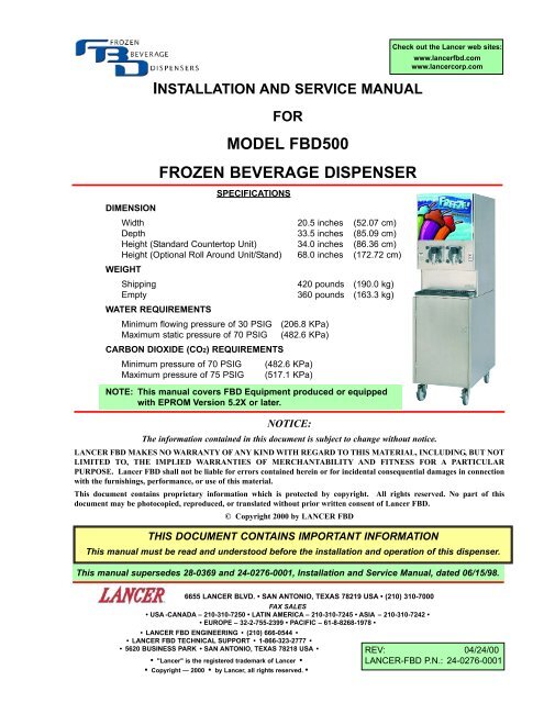
INSTALLATION AND SERVICE MANUAL<br />
FOR<br />
<strong>MODEL</strong> <strong>FBD500</strong><br />
<strong>FROZEN</strong> <strong>BEVERAGE</strong> <strong>DISPENSER</strong><br />
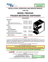
SPECIFICATIONS<br />
DIMENSION<br />
Width 20.5 inches (52.07 cm)<br />
Depth 33.5 inches (85.09 cm)<br />
Height (Standard Countertop Unit) 34.0 inches (86.36 cm)<br />
Height (Optional Roll Around Unit/Stand) 68.0 inches (172.72 cm)<br />
WEIGHT<br />
Shipping 420 pounds (190.0 kg)<br />
Empty 360 pounds (163.3 kg)<br />
WATER REQUIREMENTS<br />
Minimum flowing pressure of 30 PSIG (206.8 KPa)<br />
Maximum static pressure of 70 PSIG (482.6 KPa)<br />
CARBON DIOXIDE (CO2) REQUIREMENTS<br />
Minimum pressure of 70 PSIG (482.6 KPa)<br />
Maximum pressure of 75 PSIG (517.1 KPa)<br />
NOTE: This manual covers FBD Equipment produced or equipped<br />
with EPROM Version 5.2X or later.<br />
NOTICE:<br />
The information contained in this document is subject to change without notice.<br />
Check out the Lancer web sites:<br />
www.lancerfbd.com<br />
www.lancercorp.com<br />
LANCER FBD MAKES NO WARRANTY OF ANY KIND WITH REGARD TO THIS MATERIAL, INCLUDING, BUT NOT<br />
LIMITED TO, THE IMPLIED WARRANTIES OF MERCHANTABILITY AND FITNESS FOR A PARTICULAR<br />
PURPOSE. Lancer FBD shall not be liable for errors contained herein or for incidental consequential damages in connection<br />
with the furnishings, performance, or use of this material.<br />
This document contains proprietary information which is protected by copyright. All rights reserved. No part of this<br />
document may be photocopied, reproduced, or translated without prior written consent of Lancer FBD.<br />
© Copyright 2000 by LANCER FBD<br />
THIS DOCUMENT CONTAINS IMPORTANT INFORMATION<br />
This manual must be read and understood before the installation and operation of this dispenser.<br />
This manual supersedes 28-0369 and 24-0276-0001, Installation and Service Manual, dated 06/15/98.<br />
6655 LANCER BLVD. • SAN ANTONIO, TEXAS 78219 USA • (210) 310-7000<br />
FAX SALES<br />
• USA -CANADA – 210-310-7250 • LATIN AMERICA – 210-310-7245 • ASIA – 210-310-7242 •<br />
• EUROPE – 32-2-755-2399 • PACIFIC – 61-8-8268-1978 •<br />
• LANCER FBD ENGINEERING • (210) 666-0544 •<br />
• LANCER FBD TECHNICAL SUPPORT • 1-866-323-2777 •<br />
• 5620 BUSINESS PARK • SAN ANTONIO, TEXAS 78218 USA •<br />
• "Lancer" is the registered trademark of Lancer •<br />
• Copyright — 2000 • by Lancer, all rights reserved. •<br />
REV: 04/24/00<br />
LANCER-FBD P.N.: 24-0276-0001
TABLE OF CONTENTS<br />
SPECIFICATIONS ...................................................................................................................................COVER<br />
NOTICE ...................................................................................................................................................COVER<br />
TABLE OF CONTENTS ......................................................................................................................................i<br />
INSTALLATION CHECKLIST ...........................................................................................................................iii<br />
1. PREPARING THE LOCATION ....................................................................................................................1<br />
1.1 LOCATION REQUIREMENTS FOR THE <strong>FBD500</strong> ............................................................................1<br />
1.2 ADDITIONAL REQUIREMENTS (TO BE PROVIDED BY THE CUSTOMER) ..................................1<br />
2. RECEIVING AND UNPACKING UNIT.........................................................................................................1<br />
2.1 RECEIVING........................................................................................................................................1<br />
2.2 UNPACKING ......................................................................................................................................1<br />
3. POSITIONING THE UNIT............................................................................................................................3<br />
3.1 COMMON METHODS OF POSITIONING.........................................................................................3<br />
4. CONNECTING TO ELECTRICAL POWER ................................................................................................4<br />
5. CONNECTING WATER, CO2, AND SYRUP ...............................................................................................5<br />
5.1 BAG-IN-BOX (BIB) INSTALLATION...................................................................................................5<br />
5.2 FIVE GALLON (FIGAL) REFILLABLE TANK INSTALLATION...........................................................7<br />
6. STARTING THE UNIT .................................................................................................................................8<br />
<strong>MODEL</strong> 500 FCB BRIXING PROCEDURES .............................................................................................11<br />
CRITICAL REGULATOR AND FLOW CONTROL SETTINGS ..................................................................12<br />
7. OPERATION OF THE <strong>DISPENSER</strong>..........................................................................................................12<br />
7.1 OPERATING ELECTRONIC CONTROLS .......................................................................................12<br />
7.2 MACHINE ACCESS .........................................................................................................................16<br />
7.3 MACHINE SETTINGS......................................................................................................................16<br />
7.4 READOUTS......................................................................................................................................17<br />
7.5 MANUAL ON/OFF............................................................................................................................18<br />
7.6 BASE CHANGES .............................................................................................................................18<br />
7.7 MACHINE TOTALS ..........................................................................................................................18<br />
7.8 LOAD ALL DEFAULTS .....................................................................................................................19<br />
8. CLEANING AND SANITIZING THE UNIT ................................................................................................19<br />
8.1 GENERAL INFORMATION ..............................................................................................................19<br />
8.2 REQUIRED CLEANING EQUIPMENT.............................................................................................19<br />
8.3 DAILY CLEANING OF THE UNIT ....................................................................................................19<br />
8.4 SANITIZING THE SYRUP SYSTEMS .............................................................................................20<br />
9. BASICS OF OPERATION .........................................................................................................................20<br />
9.1 MAKING ADJUSTMENTS TO THE <strong>FBD500</strong> ...................................................................................20<br />
10. CHANGING FACTORY SET LIQUID LEVEL CONTROL.........................................................................22<br />
10.1 BEFORE CHANGING LEVEL CONTROL SETTINGS ....................................................................22<br />
10.2 CHANGING THE DEFAULT LEVEL CONTROL SETTING .............................................................23<br />
10.3 DRINK TOO HARD AND COLD.......................................................................................................23<br />
10.4 DRINK TOO LIQUID ........................................................................................................................23<br />
10.5 RECOMMENDED LEVEL CONTROL SETTINGS...........................................................................23<br />
11. CHANGING FACTORY THAW AND FREEZE SETTINGS.......................................................................24<br />
11.1 BEFORE CHANGING THAW AND FREEZE SETTINGS................................................................24<br />
11.2 CHANGING THAW AND FREEZE SETTINGS................................................................................24<br />
12. CRITICAL INFORMATION ........................................................................................................................25<br />
12.1 DEFROST AND RUN TIME DELAY.................................................................................................25<br />
12.2 CHAMBERS 90% FULL ON INITIAL SET UP .................................................................................25<br />
12.3 LINE VOLTAGE DROP ....................................................................................................................25<br />
12.4 LONG TUBING RUNS .....................................................................................................................25<br />
13. TROUBLESHOOTING GUIDE ..................................................................................................................25<br />
STARTUP PROBLEMS..............................................................................................................................25<br />
DRINK QUALITY........................................................................................................................................26<br />
ELECTRONIC CONTROLS.......................................................................................................................28<br />
MECHANICAL............................................................................................................................................29<br />
ELECTRICAL .............................................................................................................................................29<br />
WATER.......................................................................................................................................................30<br />
SYRUP.......................................................................................................................................................30<br />
CO2 ..........................................................................................................................................................30<br />
REFRIGERATION......................................................................................................................................30<br />
LCD DISPLAY ERROR MESSAGES.........................................................................................................31<br />
i
LCD DISPLAY MESSAGES ......................................................................................................................32<br />
LCD DISPLAY ERROR MESSAGES........................................................................................................33<br />
WARNING LIGHTS....................................................................................................................................33<br />
14. ILLUSTRATIONS, PARTS LISTINGS, AND DIAGRAMS.........................................................................34<br />
14.1 MOUNTING DIAGRAM..................................................................................................................34<br />
14.2 FLOW DIAGRAM/SCHEMATIC.....................................................................................................35<br />
14.3. WIRING DIAGRAM/50-60HZ SCHEMATIC...................................................................................36<br />
14.4 <strong>DISPENSER</strong> FRAME.....................................................................................................................37<br />
14.5 ELECTRICAL BOX ASSEMBLY ...............................................................................................38-39<br />
14.6 FAN SHROUD/FAN MOTOR ASSEMBLY................................................................................40-41<br />
14.7 FREEZE PACK/MANIFOLD ASSEMBLY WITH HOSES .........................................................42-43<br />
14.8 GEAR MOTOR ASSEMBLY ..........................................................................................................44<br />
14.9 COMPONENT LAYOUT.................................................................................................................45<br />
14.10 WATER PRESSURE REDUCING VALVE ASSEMBLY............................................................46-47<br />
14.11 HEADER BLOCK ASSEMBLY (FLOWMATIC BRIX) ...............................................................48-49<br />
14.12 REFRIGERATION SYSTEM COMPONENT LAYOUT .............................................................50-51<br />
14.13 COMPONENT LAYOUT AND DETAILS ...................................................................................52-53<br />
14.14 DOOR ASSEMBLY AND DETAILS...........................................................................................54-55<br />
14.15 LABEL LOCATIONS ......................................................................................................................56<br />
14.16 TOP AND REAR PANEL ASSEMBLIES ........................................................................................57<br />
14.17 LEFT AND RIGHT PANEL ASSEMBLIES .....................................................................................58<br />
14.18 LOWER HEADER SUB ASSEMBLY .............................................................................................59<br />
14.19 HEADER BLOCK ASSEMBLY WITH NYLON HOSE ASSEMBLY................................................60<br />
ii
INSTALLATION CHECKLIST<br />
This checklist is provided for dispenser installation and it is intended to be used in conjunction with this<br />
Installation and Service Manual. Refer to this manual for detailed instructions.<br />
Checked Step Operation<br />
NOTES:<br />
A<br />
B<br />
C<br />
D<br />
E<br />
F<br />
G<br />
H<br />
I<br />
J<br />
K<br />
L<br />
M<br />
N<br />
O<br />
Unpack dispenser. Check for damage. See Section 2, this manual.<br />
Place dispenser on sturdy level counter. See Sections 1 and 3, this manual.<br />
Note: Empty dispenser weighs 360 pounds (163.3 kg).<br />
IMPORTANT: Refer to Section 4, this manual, for power supply information.<br />
Connect to electrical power. Verify 220V single phase supply voltage with a<br />
voltmeter. Verify 3-wire supply cord for 60Hz and 50Hz.<br />
Note: A 10% buck and boost transformer must be used if line voltage is<br />
below 215VAC or above 245VAC.<br />
Connect SYRUP, WATER, and CO2 lines to the manifold connections at the rear<br />
of the dispenser. Note: See Section 5, this manual<br />
Turn on WATER. Check for leaks. A FLOJET (or SHURflo) boost pump for water<br />
is located inside the dispenser.<br />
Connect SYRUP lines to the BIB (Bag-In-Box) or figal tanks. Check for leaks.<br />
Open CO2 supply valve. Adjust supply regulator to 105-120 PSIG (723.9 to<br />
827.3 KPa). Re-check water and syrup supply lines for leaks.<br />
Purge the air from the chambers by filling each with CO2. Fill and purge each<br />
chamber three (3) times. Note: Refer to Section 6, this Manual, for details on<br />
filling the chambers.<br />
CAUTION: Operating with Brix level below 13 may cause damage to the<br />
dispenser.<br />
Adjust Brix level. Recommended setting is 13.5 - 15. See Section 6, this<br />
manual.<br />
Press the “FILL” button on the control panel to fill the chamber with SYRUP<br />
solution. Fill the chamber to 90% full. Note: Use the relief valve on the faceplate<br />
to slowly bleed off some CO2 as the chamber fills. If gear motors are not turned<br />
on initially for two (2) minutes, a two minute delay will occur after RUN or<br />
DEFROST is pressed. Never run gear motors without liquid in the chambers.<br />
Press the “DEF” (defrost) button on the control panel.<br />
Note: The “DEF” button automatically defrosts the dispenser and sets the liquid<br />
baseline. Before starting the dispenser, check voltage offset following the<br />
procedure in Section 7.3, this manual. Then press the “RUN” button to freeze the<br />
product.<br />
After freeze down, check the drink for quality.<br />
Note: Refer to Section 9, this manual, for details on adjusting drink quality.<br />
Drink MUST be given time to stabilize prior to making initial adjustments.<br />
Check SYRUP, WATER, and CO2 lines for leaks.<br />
Seal dispenser to the countertop with silicone sealant. See Section 3, this<br />
manual.<br />
Replace side panels.<br />
iii
DO NOT USE<br />
WHEN LIGHT<br />
IS ON<br />
DO NOT USE<br />
WHEN LIGHT<br />
IS ON<br />
1. PREPARING THE LOCATION<br />
1.1 LOCATION REQUIREMENTS FOR THE <strong>FBD500</strong><br />
A. A sturdy, level surface for placement. The empty countertop unit weighs 360 pounds (163.3 kg).<br />
When selecting a counter location, insure counter will support an operating unit. If more than<br />
one unit is installed, the counter must be able to support the corresponding weight.<br />
B. Adequate space (see Figure 1) which will allow:<br />
1. Removal of side panels, if service is necessary (Item A, Figure 1).<br />
2. Air circulation around vents in back and top of unit (Item B, Figure 1).<br />
3. A well ventilated room.<br />
4. Room temperature 50°F to 90°F (10°C to 32.5°C); however, the environment should be<br />
stable with no abrupt changes in temperature.<br />
5. Limited exposure to direct sunlight or chemicals.<br />
12 INCHES<br />
B<br />
LANCER FBD<br />
LEFT SIDE SAN ANTONIO, TEXAS - USA RIGHT SIDE<br />
2 INCHES<br />
A<br />
Figure 1<br />
1.2 ADDITIONAL REQUIREMENTS (TO BE PROVIDED BY THE CUSTOMER)<br />
CAUTION<br />
IF A BULK CO2 SUPPLY IS USED AND IS SET ABOVE 70 PSIG (482.6 KPA), A SECONDARY<br />
REGULATOR MUST BE USED.<br />
A. CO2 tank and regulator, or bulk CO2 supply.<br />
B. Syrup (Bag-in-Box), or syrup tank [five (5) gallon (figal) option].<br />
NOTE<br />
Syrup tank requires a Syrup Restart Valve (SRV).<br />
2. RECEIVING AND UNPACKING UNIT<br />
2.1 RECEIVING<br />
Each unit is tested and thoroughly inspected before shipment. At time of shipment, the carrier<br />
accepts the unit(s) and any claim for damages must be made with the carrier. Upon receiving unit(s)<br />
from the delivering carrier, carefully inspect carton(s) for visible indication(s) of damage. If damage<br />
exists, have carrier note same on bill of lading and file a claim with the carrier.<br />
2.2 UNPACKING<br />
A. Carefully cut banding from shipping carton and remove.<br />
B. Remove top portion of carton by lifting up (see Figure 2). Remove protective side panels and<br />
four (4) corner protectors (see Figure 3).<br />
1
FLOW<br />
<strong>FROZEN</strong><br />
LANCER<br />
<strong>BEVERAGE</strong><br />
<strong>DISPENSER</strong>S<br />
INSTALLATION AND SERVICE MANUAL<br />
FOR<br />
<strong>MODEL</strong> <strong>FBD500</strong><br />
<strong>FROZEN</strong> <strong>BEVERAGE</strong> <strong>DISPENSER</strong><br />
SPECIFICATIONS<br />
DIMENSION<br />
WIDTH<br />
20.5 INCHES (52.07 CM)<br />
DEPTH<br />
33.5 INCHES (85.09 CM)<br />
HEIGHT (STANDARD COUNTERTOP UNIT) 34.0 INCHES (86.36 CM)<br />
HEIGHT (OPTIONAL ROLL AROUND UNIT/STAND) 68.0 INCHES (172.72)<br />
SHIPPING<br />
420 POUNDS (190.0 KG)<br />
EMPTY<br />
360 POUNDS (163.3 KG)<br />
WEIGHT<br />
WATER REFQUIREMENTS<br />
MINIMUM FLOWING PRESSURE OF 30 PSIG (206.8 KPa)<br />
MAXIMUN STATIC PRESSURE OF 70 PSIG (482.6 KPa)<br />
2<br />
CARBON DIOXIDE (CO ) REQUIREMENTS<br />
MINIMUM PRESSURE OF 70 PSIG (482.6 KPa)<br />
MAXIMUM PRESSURE OF 75 PSIG (517.1 KPa)<br />
DO NOT USE<br />
WHEN LIGHT<br />
IS ON<br />
LANCER<br />
C COPYRIGHT 1999 BY LANCER FBD<br />
THIS DOCUMENT CONTAINS IMPORTANT INFORMATION<br />
THIS MANUAL MUST BE READ AND UNDERSTOOD BEFORE THE INSTALLATION AND OPERATION OF THIS <strong>DISPENSER</strong>.<br />
THIS MANUAL SUPERSEDES 28-0369 AND 24-0276-0001, INSTALLATION AND SERVICE MANUAL, DATED 06/15/98<br />
6655 LANCER BLVD. SAN ANTONIO, TEXAS 78219 USA (210) 310-7000<br />
LANCER<br />
FAX SALES<br />
USA-CANADA-210-310-7250 LATIN AMERICA-210-310-7245 ASIA-210-310-7242<br />
EUROPE-32-2-714-0999 PACIFIC-61-8-8268-1978<br />
LANCER FBD ENGINEERING<br />
REV: 11/23/99<br />
HOUSTON, TEXAS USA 713-681-1842<br />
LANCER-FBD P.N.: 24-0276-0002<br />
"LANCER" IS THE REGISTEDED TTRADEMARK OF LANCER<br />
LANCER P.N.: 28-0369/01<br />
COPYRIGHT-1999 BY LANCER, ALL RIGHTS RESERVED.<br />
DO NOT USE<br />
WHEN LIGHT<br />
IS ON<br />
TURN<br />
AND LIFT<br />
LIFT & TURN<br />
MEDIUM<br />
FLOW<br />
A Great Way<br />
To Enjoy A<br />
NOTICE:<br />
THE INFORMATION CONTAINED IN THIS DOCUMENT IS SUBJECT TO CHANGE WITHOUT NOTICE.<br />
LANCER FBD MAKES NO WARRANTY OF ANY KIND WITH REGARD TO THIS MATERIAL, INCLUDING, BUT NOT<br />
LIMITED TO, THE IMPLIED WARRANTIES OF MERCHANTABILITY AND FITNESS FOR A PARTICULAR<br />
PURPOSE. LANCER FBD SHALL NOT BE LIABLE FOR ERRORS CONTAINED HEREIN OR FOR INCIDENTAL CONSEQUENTIAL DAMAGES IN CONNECTION<br />
WITH THE FURNISHINGS, PERFORMANCE, OR USE OF THIS MATERIAL.<br />
THIS DOCUMENT CONTAINS PROPRIETARY INFORMATION WHICH IS PROTECTED BY COPYRIGHT. ALL RIGHTS RESERVED. NO PART OF THIS<br />
DOCUMENT MAY BE PHOTOCOPIED, REPRODUCED, OR TRANSLATED WITHOUT PRIOR WRITTEN CONSENT OF LANCER FBD.<br />
A Great Way<br />
To Enjoy A<br />
Coke<br />
Coke<br />
Figure 2<br />
Figure 3<br />
C. Remove drip tray, accessory kit and manual from top packaging (see Figure 3).<br />
D. Remove plastic bag.<br />
E. Remove side panels from unit (see Figure 4).<br />
WARNING<br />
TO AVOID PERSONAL INJURY OR DAMAGE, DO NOT ATTEMPT TO LIFT THE UNIT WITHOUT<br />
HELP. THE EMPTY UNIT WEIGHS APPROXIMATELY 360 POUNDS (163.3 KG). USE OF A<br />
MECHANICAL LIFT IS RECOMMENDED.<br />
CAUTION<br />
USE GLOVES TO PROTECT HANDS FROM BEING INJURED BY THE EDGES OF CROSS<br />
BRACING.<br />
F. Using proper lifting techniques, lift unit up by plywood shipping base, and remove lower portion<br />
of carton (see Figure 4).<br />
G. Inspect unit for concealed damage. If evident, immediately notify delivering carrier and file a<br />
claim against same.<br />
SCREW<br />
SCREW<br />
Figure 4<br />
2<br />
Figure 5
LANCER<br />
<strong>FROZEN</strong><br />
<strong>BEVERAGE</strong><br />
<strong>DISPENSER</strong>S<br />
INSTALLATION AND SERVICE MANUAL<br />
<strong>FROZEN</strong> <strong>BEVERAGE</strong> <strong>DISPENSER</strong><br />
SPECIFICATIONS<br />
DIMENSION<br />
WIDTH<br />
20.5 INCHES (52.07 CM)<br />
DEPTH<br />
33.5 INCHES (85.09 CM)<br />
HEIGHT (STANDARD COUNTERTOP UNIT) 34.0 INCHES (86.36 CM)<br />
HEIGHT (OPTIONAL ROLL AROUND UNIT/STAND) 68.0 INCHES (172.72)<br />
DO NOT USE<br />
WHEN LIGHT<br />
IS ON<br />
WEIGHT<br />
SHIPPING<br />
420 POUNDS (190.0 KG)<br />
EMPTY<br />
360 POUNDS (163.3 KG)<br />
WATER REFQUIREMENTS<br />
MINIMUM FLOWING PRESSURE OF 30 PSIG (206.8 KPa)<br />
MAXIMUN STATIC PRESSURE OF 70 PSIG (482.6 KPa)<br />
2<br />
CARBON DIOXIDE (CO ) REQUIREMENTS<br />
MINIMUM PRESSURE OF 70 PSIG (482.6 KPa)<br />
MAXIMUM PRESSURE OF 75 PSIG (517.1 KPa)<br />
NOTICE:<br />
THE INFORMATION CONTAINED IN THIS DOCUMENT IS SUBJECT TO CHANGE WITHOUT NOTICE.<br />
LANCER FBD MAKES NO WARRANTY OF ANY KIND WITH REGARD TO THIS MATERIAL, INCLUDING, BUT NOT<br />
LIMITED TO, THE IMPLIED WARRANTIES OF MERCHANTABILITY AND FITNESS FOR A PARTICULAR<br />
PURPOSE. LANCER FBD SHALL NOT BE LIABLE FOR ERRORS CONTAINED HEREIN OR FOR INCIDENTAL CONSEQUENTIAL DAMAGES IN CONNECTION<br />
WITH THE FURNISHINGS, PERFORMANCE, OR USE OF THIS MATERIAL.<br />
THIS DOCUMENT CONTAINS PROPRIETARY INFORMATION WHICH IS PROTECTED BY COPYRIGHT. ALL RIGHTS RESERVED. NO PART OF THIS<br />
DOCUMENT MAY BE PHOTOCOPIED, REPRODUCED, OR TRANSLATED WITHOUT PRIOR WRITTEN CONSENT OF LANCER FBD.<br />
C<br />
COPYRIGHT 1999 BY LANCER FBD<br />
LANCER<br />
THIS DOCUMENT CONTAINS IMPORTANT INFORMATION<br />
THIS MANUAL MUST BE READ AND UNDERSTOOD BEFORE THE INSTALLATION AND OPERATION OF THIS <strong>DISPENSER</strong>.<br />
THIS MANUAL SUPERSEDES 28-0369 AND 24-0276-0001, INSTALLATION AND SERVICE MANUAL, DATED 06/15/98<br />
6655 LANCER BLVD. SAN ANTONIO, TEXAS 78219 USA (210) 310-7000<br />
LANCER<br />
FAX SALES<br />
USA-CANADA-210-310-7250 LATIN AMERICA-210-310-7245 ASIA-210-310-7242<br />
EUROPE-32-2-714-0999 PACIFIC-61-8-8268-1978<br />
LANCER FBD ENGINEERING<br />
REV: 11/23/99<br />
HOUSTON, TEXAS USA 713-681-1842<br />
LANCER-FBD P.N.: 24-0276-0002<br />
"LANCER" IS THE REGISTEDED TTRADEMARK OF LANCER<br />
LANCER P.N.: 28-0369/01<br />
COPYRIGHT-1999 BY LANCER, ALL RIGHTS RESERVED.<br />
DO NOT USE<br />
WHEN LIGHT<br />
IS ON<br />
TURN<br />
AND LIFT<br />
LIFT & TURN<br />
MEDIUM<br />
H. Remove shipping board from bottom of unit by locating unit so that one side is off the counter<br />
top or table, allowing access to, and removing, nuts and bolts securing unit to the shipping board<br />
(see Figure 4).<br />
I. Locate the following items (see Figure 6):<br />
1. Assembled FBD unit.<br />
2. Drip tray with cup rest grill and support ring.<br />
3. Installation and Service Manual for <strong>FBD500</strong>.<br />
4. Bag containing loose screws and drain adapter.<br />
NOTE<br />
Contact dealer/distributor if any parts are missing or damaged.<br />
FOR<br />
<strong>MODEL</strong> <strong>FBD500</strong><br />
3<br />
4<br />
PARTS<br />
BAG<br />
2<br />
1<br />
Figure 6<br />
3. POSITIONING THE UNIT<br />
CAUTION<br />
IF USING A COUNTER TO POSITION THE UNIT, BE SURE THAT THE COUNTER WILL<br />
SUPPORT THE WEIGHT OF THE MACHINE [APPROXIMATELY 360 POUNDS (163.3 KG),<br />
EMPTY WEIGHT].<br />
CHECK POSITIONING WITH THE MOUNTING DIAGRAM (SEE PAGE 34) BEFORE LIFTING<br />
MACHINE TO COUNTER. (REFER TO SECTION 14.1 OF THIS MANUAL FOR HOLE<br />
LOCATIONS.)<br />
INSURE THAT THERE IS ADEQUATE AIR SPACE ABOVE [MINIMUM OF TWELVE (12) INCHES<br />
(30.48 CM)] AND BEHIND [MINIMUM OF TWO (2) INCHES (5.08 CM)] THE UNIT FOR<br />
VENTILATION.<br />
3.1 COMMON METHODS OF POSITIONING<br />
A. The two most common methods of positioning the unit are:<br />
1. Flush mounting - The most common method used; positions the unit directly onto the<br />
countertop surface.<br />
2. Roll around base cabinet - The unit rests on top of the optional roll around cabinet. This<br />
method allows the unit to be rolled out of position for cleaning.<br />
B. Use the following guidelines to position and secure a flush mount unit to the countertop.<br />
1. There are four (4) threaded mounting holes (3/8-16 UNC) in the base of the frame, should<br />
the unit need to be permanently mounted (refer to Section 14.1 of this manual for hole<br />
locations). Prepare the surface for mounting, but do not attach the unit at this time (see<br />
Figure 7).<br />
3
FLOW<br />
CAUTION<br />
USE PROPER EQUIPMENT AND LIFTING TECHNIQUES WHEN LIFTING OR MOVING<br />
EQUIPMENT. THE UNIT IS TOP HEAVY. MAINTAIN UNIT IN A VERTICAL, UPRIGHT POSITION<br />
WHEN LIFTING AND POSITIONING THE UNIT. (MECHANICAL LIFT RECOMMENDED.)<br />
2. With the side panels removed, lift the unit by the frame cross bracing. Move the unit to the<br />
counter.<br />
3. Position the unit so that the drip tray is completely supported by the countertop (if possible).<br />
4. After completing the installation and before replacing side panels, the frame should be<br />
sealed to the counter with an FDA approved sealant (see Figure 8).<br />
4. CONNECTING TO ELECTRICAL POWER<br />
Optional mounting<br />
pattern two (2) places<br />
Drill 1/2" Diameter hole<br />
Typical four (4) places<br />
Apply FDA approved<br />
sealant around the frame.<br />
Figure 7 Figure 8<br />
WARNING<br />
THIS UNIT MUST BE PROPERLY ELECTRICALLY GROUNDED TO AVOID POSSIBLE FATAL<br />
ELECTRICAL SHOCK OR SERIOUS INJURY TO THE OPERATOR. THE POWER CORD IS<br />
PROVIDED WITH A THREE PRONG GROUNDED PLUG. IF A THREE-HOLE GROUNDED<br />
ELECTRICAL OUTLET IS NOT AVAILABLE, USE AN APPROVED METHOD TO GROUND THE UNIT.<br />
4.1 Use the following guidelines to connect electrical power to the machine for 50-60 Hz service.<br />
A. The machine requires 220 volts alternating current. If line voltage is below 215VAC or above<br />
245VAC, a 10% buck and boost transformer must be used. Operation below 215VAC or above<br />
245VAC may damage the unit and cause inconsistent performance. This also voids all<br />
warranties.<br />
B. The unit is a single phase machine. If connected to a “delta” three phase electrical system, the<br />
machine must not be connected to the high leg as one of the two (2) power legs. This will cause<br />
the machine to malfunction. If a delta system is used, check each leg to ground to insure the<br />
“low legs” are used.<br />
CAUTION<br />
THIS UNIT WILL NOT WORK PROPERLY IF THERE IS MORE THAN A 10V VOLTAGE DROP IN<br />
THE POWER SUPPLY LINE BETWEEN THE POWER SOURCE AND THE MACHINE. A DROP<br />
OF MORE THAN 10V INDICATES UNDERSIZED WIRING OR EXCESSIVELY LONG RUNS.<br />
C. The unit must be installed on a “single branch” circuit (on a circuit by itself), protected by a<br />
30 Amp service and a 30 Amp fuse for both 50 and 60 Hz.<br />
WARNING<br />
ALWAYS DISCONNECT ELECTRICAL POWER TO THE UNIT TO PREVENT PERSONAL<br />
INJURY BEFORE ATTEMPTING ANY INTERNAL MAINTENANCE. ONLY QUALIFIED<br />
PERSONNEL SHOULD SERVICE INTERNAL COMPONENTS OR ELECTRICAL WIRING.<br />
4
CAUTION<br />
IF A DELTA THREE PHASE POWER SOURCE IS USED, USE THE TWO LOW VOLTAGE LEGS.<br />
DO NOT USE THE SINGLE HIGH LEG. TO DO SO WILL CAUSE SOFTWARE TO<br />
MALFUNCTION.<br />
D. It is recommended that a 3 conductor, 30 Amp, “L” receptacle be used (see Figure 9). Using a<br />
voltmeter, check voltage across both “hot legs” (240VAC) and between ground and each “hot<br />
leg” (120VAC). Check for continuity on the plug across both “hot legs” and no continuity<br />
between each “hot leg” and ground (see Figure 10).<br />
WARNING<br />
DO NOT CONNECT POWER TO THE MACHINE AT THIS TIME.<br />
E. If using an existing outlet, check it for proper wiring prior to installation. If readings are not as<br />
shown in Figure 9, the receptacle is not wired correctly and damage to the machine will<br />
occur if plugged in. Do NOT connect power to machine at this time.<br />
240V<br />
GROUND<br />
120V<br />
120V<br />
Voltage Readings on Receptacle<br />
Figure 9<br />
5. CONNECTING WATER, CO2, AND SYRUP<br />
No Continuity Readings Between<br />
Ground and Either Leg<br />
Figure 10<br />
CONTINUITY<br />
5.1 BAG-IN-BOX (BIB) INSTALLATION<br />
Use the following steps for connecting water, CO2, and syrup. The unit can be connected using one<br />
of the following methods:<br />
A. Water Connections<br />
IMPORTANT<br />
A WATER PUMP AND WATER REGULATOR ARE INSTALLED IN THE BASE OF THE<br />
MACHINE. A WATER FILTER SHOULD BE INSTALLED IN THE WATER LINE BEFORE<br />
BEING CONNECTED TO THE MACHINE. THE UNIT REQUIRES A MINIMUM OF 30 PSIG<br />
(206.8 KPA) WATER PRESSURE. FLUSH THE FILTER WITH SEVERAL GALLONS<br />
(12-15 LITERS) OF WATER PRIOR TO USE TO INSURE BLACK CARBON “FINES” ARE NOT<br />
FED INTO THE FREEZING CHAMBER.<br />
1. Using 3/8 inch tubing, connect the unit to a potable water supply. Bulkhead fittings are<br />
located in the rear of the machine. The label adjacent to the bulkhead denotes proper hose<br />
connections (see Figure 13). Install a shutoff valve in the water line as close to the unit as<br />
practical and convenient.<br />
NOTE<br />
Water pipe connections and fixtures directly connected to a potable water supply shall be<br />
sized, installed, and maintained according to Federal, State and local laws.<br />
2. Clear the line by running a minimum of two (2) gallons (7.57 liters) of water through the line<br />
before attaching the line to the bulkhead fitting labeled “WATER IN”.<br />
NOTE<br />
Do not turn water on at this time.<br />
3. Fabricate a 3/8 inch supply line to the “WATER IN” connector on the rear of the unit.<br />
5
B. CO2 Connections<br />
WARNING<br />
CO2 DISPLACES OXYGEN. STRICT ATTENTION MUST BE OBSERVED IN THE<br />
PREVENTION OF CO2 (CARBON DIOXIDE) GAS LEAKS IN THE ENTIRE CO2 AND SOFT<br />
DRINK SYSTEM. IF A CO2 GAS LEAK IS SUSPECTED, IMMEDIATELY VENTILATE THE<br />
CONTAMINATED AREA BEFORE ATTEMPTING TO REPAIR THE LEAK.<br />
PERSONNEL EXPOSED TO HIGH CONCENTRATIONS OF CO2 GAS WILL EXPERIENCE<br />
TREMORS WHICH ARE FOLLOWED RAPIDLY BY LOSS OF CONSCIOUSNESS AND<br />
SUFFOCATION.<br />
CAUTION<br />
TO AVOID PERSONAL INJURY AND/OR PROPERTY DAMAGE, ALWAYS SECURE CO2<br />
CYLINDERS IN AN UPRIGHT POSITION WITH A SAFETY CHAIN TO PREVENT CYLINDERS<br />
FROM FALLING OVER. SHOULD THE VALVE BECOME ACCIDENTALLY DAMAGED OR<br />
BROKEN OFF, A CO2 CYLINDER CAN CAUSE SERIOUS PERSONAL INJURY.<br />
1. The CO2 supply may be attached to either an independent tank and regulator, or to a branch<br />
line of an existing bulk CO2 system. Install a shutoff valve and a supply regulator in the line<br />
from any existing branch. Fabricate a 1/4 inch supply line to reach the “CO2 IN” connector<br />
on the rear of the unit.<br />
2. Connect the CO2 supply line to the CO2 connector on the dispenser.<br />
3. Splice a 1/4 inch barb cross into the CO2 supply line and run lines to the syrup pumps.<br />
CAUTION<br />
CHECK ALL SUPPLY LINES TO INSURE THAT THEY ARE CONNECTED TO THE CORRECT<br />
FITTINGS. IF LINES ARE NOT CONNECTED PROPERLY, COMPONENTS WILL BE<br />
DAMAGED.<br />
4. Check all CO2 connections for tightness.<br />
NOTE<br />
Do NOT turn on the CO2 at this time.<br />
C. Syrup Connections<br />
1. Fabricate two (2) 1/4 inch supply lines to reach from the “SYRUP #1 BIB Pump” and the<br />
“SYRUP #2 BIB Pump” to the “SYRUP #1 LEFT” and “SYRUP #2 RIGHT” connectors on<br />
the rear of the unit.<br />
NOTE<br />
If the syrup inlet line exceeds 25 feet (7.62 meters) in length,<br />
use a 3/8 inch supply line.<br />
2. Installations requiring long runs of tubing [30 - 50 feet<br />
(9.14 - 15.24 meters)] may encounter problems. The<br />
machine’s sensors may indicate that the machine is out of<br />
syrup or water. Consider the following solutions:<br />
a. Increase the tubing size from 1/4 inch diameter to<br />
3/8 inch diameter.<br />
b. Install booster pumps in the supply lines.<br />
c. Increase CO2 regulator pressure to 120 PSIG<br />
(827.3 KPa) [from the normal 105 PSIG (723.9 KPa)] on<br />
the primary regulator at the CO2 tank or supply.<br />
3. Connect all lines and check all fittings for tightness.<br />
Flojet Syrup Pump<br />
Figure 11<br />
6
5.2 FIVE GALLON (FIGAL) REFILLABLE TANK INSTALLATION<br />
This installation involves the use of refillable five gallon (figal) tank CO2 and syrup supply units. The<br />
figures that accompany these steps illustrate the proper routing of hoses for this installation.<br />
A. Water Connections<br />
IMPORTANT<br />
A WATER PUMP AND WATER REGULATOR ARE INSTALLED IN THE BASE OF THE<br />
MACHINE. A WATER FILTER SHOULD BE INSTALLED IN THE WATER LINE BEFORE<br />
BEING CONNECTED TO THE MACHINE. THE UNIT REQUIRES A MINIMUM OF 30 PSIG<br />
(206.8 KPA) WATER PRESSURE. FLUSH THE FILTER WITH SEVERAL GALLONS<br />
(12-15 LITERS) OF WATER PRIOR TO USE TO INSURE BLACK CARBON “FINES” ARE NOT<br />
FED INTO THE FREEZING CHAMBER.<br />
1. Using 3/8 inch tubing, connect the unit to a potable water supply. Bulkhead fittings are<br />
located in the rear of the machine. The label adjacent to the bulkhead denotes proper hose<br />
connections (see Figure 13). Install a shutoff valve in the water line as close to the unit as<br />
practical and convenient.<br />
NOTE<br />
Water pipe connections and fixtures directly connected to a potable water supply shall be<br />
sized, installed, and maintained according to Federal, State and local laws.<br />
2. Clear the line by running a minimum of two (2) gallons (7.57 liters) of water through the line<br />
before attaching the line to the bulkhead fitting labeled “WATER IN”.<br />
NOTE<br />
Do not turn water on at this time.<br />
3. Fabricate a 3/8 inch supply line to the “WATER IN” connector on the rear of the unit.<br />
B. CO2 Connections<br />
WARNING<br />
CO2 DISPLACES OXYGEN. STRICT ATTENTION MUST BE OBSERVED IN THE<br />
PREVENTION OF CO2 (CARBON DIOXIDE) GAS LEAKS IN THE ENTIRE CO2 AND SOFT<br />
DRINK SYSTEM. IF A CO2 GAS LEAK IS DETECTED OR SUSPECTED, IMMEDIATELY<br />
VENTILATE THE CONTAMINATED AREA BEFORE ATTEMPTING TO REPAIR THE LEAK.<br />
PERSONNEL EXPOSED TO HIGH CONCENTRATIONS OF CO2 GAS WILL EXPERIENCE<br />
TREMORS WHICH ARE FOLLOWED RAPIDLY BY LOSS OF CONSCIOUSNESS AND<br />
SUFFOCATION.<br />
CAUTION<br />
TO AVOID PERSONAL INJURY AND/OR PROPERTY DAMAGE, ALWAYS SECURE CO2<br />
CYLINDERS IN AN UPRIGHT POSITION WITH A SAFETY CHAIN TO PREVENT CYLINDERS<br />
FROM FALLING OVER. SHOULD THE VALVE BECOME ACCIDENTALLY DAMAGED OR<br />
BROKEN OFF, A CO2 CYLINDER CAN CAUSE SERIOUS PERSONAL INJURY.<br />
1. The CO2 supply may be attached to either an independent tank and regulator, or to a branch<br />
line of an existing bulk CO2 system. Install a shutoff valve and a supply regulator in the line<br />
from any existing branch.<br />
2. Connect the CO2 supply line to the CO2 connector on the dispenser.<br />
CAUTION<br />
CHECK ALL SUPPLY LINES TO INSURE THAT THEY ARE CONNECTED TO THE CORRECT<br />
FITTINGS. COMPONENTS WILL BE DAMAGED IF LINES ARE NOT CONNECTED<br />
PROPERLY.<br />
3. Splice a 1/4 inch barb cross into the CO2 supply line and run lines to the syrup tank.<br />
4. Check all CO2 connections for tightness.<br />
NOTE<br />
Do NOT turn on the CO2 at this time.<br />
7
C. Syrup Connections (see Figure 12)<br />
1. Fabricate two (2) 1/4 inch supply lines to reach from “SYRUP SRV #1” and “SYRUP SRV<br />
#2” to the “SYRUP #1 LEFT” and “SYRUP #2 RIGHT” connectors on the rear of the unit.<br />
Syrup pumps are not required with the five gallon (figal) refillable tanks.<br />
CAUTION<br />
SYRUP RESTART VALVES (SRV) MUST BE USED WITH SYRUP TANKS. WARRANTIES<br />
WILL BE VOID IF THE SRVs ARE NOT INSTALLED.<br />
2. The “OUT OF” devices in the machine will not function properly without the use of Syrup<br />
Restart Valves. If the “OUT OF” devices do not function, the machine will then supply only<br />
water and “freeze up”.<br />
3. To operate the SRV, press the restart button after each tank is changed. Refill will not start<br />
until the machine refreezes product, and the red light beside each chamber goes out.<br />
NOTE<br />
When replacing a figal, insure that the SYRUP SRV line to the dispenser is attached to the<br />
figal before the CO2 line is attached to the figal. This will allow the SRV to work properly.<br />
4. Installations requiring long runs of tubing<br />
[30-50 feet (9.14-15.24 meters)] may<br />
encounter problems. The machine’s sensors<br />
CO2<br />
may indicate that the machine is out of syrup<br />
or water. Consider the following solutions:<br />
a. Increase the tubing size from 1/4 inch<br />
diameter to 3/8 inch diameter.<br />
b. Install booster pumps in the supply lines.<br />
c. Increase CO2 regulator pressure to<br />
120 PSIG (827.3 KPa) [from the normal<br />
105 PSIG (723.9 KPa)] on the primary<br />
regulator at the CO2 tank or supply.<br />
5. Connect all lines and check all fittings for tightness.<br />
6. STARTING THE UNIT<br />
Syrup Restart Valve Hook Up<br />
Figure 12<br />
6.1 Use the following the steps to dispense product from the unit.<br />
WARNING<br />
THIS UNIT MUST BE PROPERLY ELECTRICALLY GROUNDED TO AVOID POSSIBLE FATAL<br />
ELECTRICAL SHOCK OR SERIOUS INJURY TO THE OPERATOR. THE POWER CORD IS<br />
PROVIDED WITH A THREE PRONG GROUNDED PLUG. IF A THREE-HOLE GROUNDED<br />
ELECTRICAL OUTLET IS NOT AVAILABLE, USE AN APPROVED METHOD TO GROUND THE<br />
UNIT.<br />
TO PREVENT PERSONAL INJURY, ALWAYS DISCONNECT ELECTRICAL POWER TO THE<br />
UNIT BEFORE ATTEMPTING TO REMOVE ANY PANELS OR PERFORM ANY MAINTENANCE.<br />
A. Insure the electrical power is disconnected from the unit.<br />
B. Release the graphic display panel by disengaging the latch located behind the right side of the<br />
lighted display. Swing the door to the full open position.<br />
C. Using a phillips head screwdriver, remove the stainless steel access panel located below the<br />
information display panel.<br />
CAUTION<br />
CHECK ALL SUPPLY LINES TO INSURE THAT THEY ARE CONNECTED TO THE CORRECT<br />
FITTINGS. IF LINES ARE NOT CONNECTED PROPERLY, COMPONENTS WILL BE DAMAGED.<br />
D. Open the water supply valve and check all water line connections for leaks.<br />
E. Connect two (2) BIB connectors to box or connect two (2) couplers to figal tanks. Check for<br />
leaks.<br />
F. If all CO2 lines and connections are secure and properly connected, open the CO2 tank valve<br />
8
and adjust the primary regulator mounted on the CO2 supply tank to 70-75 PSIG (482.6 KPa to<br />
517.1 KPa) (see Figure 13 or Figure 15). Recheck all CO2 line connections for leaks.<br />
NOTE<br />
The primary CO2 supply regulator must be set at 70-75 PSIG (482.6 KPa to 517.1 KPa) to<br />
insure 70-75 PSIG (482.6 KPa to 517.1 KPa) CO2 supply to the machine.<br />
G. Check all syrup supply connections at the rear of the machine for leaks.<br />
H. Plug unit IN to the electrical power.<br />
I. Remove splash plate and electric box cover. Check for illumination of the graphics display.<br />
J. Check for the display of information on the LCD control panel (this will read “COPYRIGHT”).<br />
Recheck voltage between L1, L2 and, between L1 and ground, and between L2 and ground for<br />
proper voltage at contactor.<br />
K. The voltage offset must be set (see Sections 7.3 and 7.4).<br />
L. Insure that the CO2 secondary regulator (located inside the machine) is adjusted to read<br />
30-32 PSIG (206.8 to 220.8 KPa).<br />
NOTE<br />
This step must be verified. See Common Readouts, “Regulated CO2” (see Section 7.4).<br />
M. Access the MANUAL ON/OFF MODE in the service menu through the control panel (see<br />
Section 7.1.C, Operating Electronic Controls, for assistance on accessing menus).<br />
N. From the MANUAL ON/OFF MODE in the service menu, fill each chamber with CO2 by activating<br />
the CO2 solenoid. Open the dispensing valve to purge all the air from the chambers. Repeat<br />
this step three (3) times on each chamber. Remember to deactivate the CO2 solenoid upon<br />
completion.<br />
O. Press down on sample valve. Run until syrup is purged through the system. This will prime the<br />
syrup pumps. Do this for both sides.<br />
Bulkhead connections<br />
on rear of unit<br />
SYRUP 2<br />
RIGHT<br />
SYRUP 1<br />
LEFT<br />
CO2<br />
WATER<br />
Syrup 2 Right<br />
Syrup 1 Left<br />
CO2 Line<br />
To water supply with<br />
shut off valve<br />
CO2 tank pressure<br />
gauge (70-75 PSIG)<br />
CO2 Line<br />
SRV (Syrup<br />
Restart Valve)<br />
Primary CO2<br />
tank regulator<br />
CO2 tank<br />
SRV<br />
(Syrup<br />
Restart<br />
Valve)<br />
CO2<br />
Section<br />
Syrup<br />
Section<br />
CO2<br />
Section<br />
Syrup<br />
Section<br />
Refillable<br />
5 gallon (figal)<br />
syrup<br />
supply tank<br />
Refillable<br />
5 gallon (figal)<br />
syrup<br />
supply tank<br />
Refillable Five Gallon (figal) Supply Tank System<br />
Figure 13<br />
9
WATER<br />
DO NOT USE<br />
WHEN LIGHT<br />
IS ON<br />
LANCER FBD<br />
LEFT SIDE SAN ANTONIO, TEXAS - USA RIGHT SIDE<br />
DO NOT USE<br />
WHEN LIGHT<br />
IS ON<br />
SYRUP 2<br />
SYRUP WATER<br />
SAMPLE VALVE<br />
"FILL" button on/off<br />
SYRUP<br />
Setting the Brix<br />
Figure 14<br />
SAMPLE TUBE<br />
P. Back the water flow control adjuster to close (counter clockwise to stop). Turn the water<br />
adjuster in (clockwise) 2 3/4 turns. Using a graduated container, take a 10 (ten) second<br />
sample of water from the sample valve (see note). Adjust water control to achieve 13 ounces<br />
of water in ten seconds. To increase the water flow, turn the adjustment screw clockwise. To<br />
decrease the water flow, turn the adjustment screw counter clockwise. Retest three (3) times<br />
for accuracy.<br />
NOTE<br />
When depressing sample tube, make sure sample valve travels until stop is reached.<br />
CAUTION<br />
RECOMMENDED BRIX SETTING IS 13.5 - 15. OPERATING THE <strong>DISPENSER</strong> BELOW THIS<br />
SETTING MAY CAUSE DAMAGE<br />
Q. Check the brix settings before filling the chambers. See Table for Model 500 FCB Brixing<br />
Procedures and brix adjustments (next page). The brix setting must be set between 13.5<br />
and 15. The flow controllers are located on the header assembly. A sample may be taken by<br />
pushing down on the sample valve while “FILL” is in the “FILL OFF” position.<br />
NOTE<br />
The sample tube (see Figure 14), connected to the sample valve, dispenses (below the freeze<br />
pack cover) into the drip tray area.<br />
CO2 secondary<br />
regulator (30-32 PSIG)<br />
Brix sample valve<br />
Flow Controller<br />
The water regulator and water<br />
pump are factory installed inside<br />
the base unit. These components<br />
may be located remotely if<br />
necessary.<br />
Fittings on rear<br />
of machine<br />
SYRUP 1<br />
LEFT<br />
RIGHT<br />
WATER<br />
CO2<br />
From water line<br />
CO2 tank pressure<br />
gauge (70-75 PSIG)<br />
CO2 primary regulator<br />
Syrup #1 Out<br />
Syrup #2 Out<br />
CO2 Out<br />
CO2 In<br />
CO2 tank<br />
Location of Key Components Involved in Set-Up and Product Adjustment (BIB Method)<br />
Figure 15<br />
10
<strong>MODEL</strong> 500 FCB BRIXING PROCEDURES<br />
TO SET BRIX<br />
Step 1 With “FILL” OFF, hold a container under the sample tube and depress sample valve fully until<br />
a good water and syrup mixture is obtained (see Note 1). This sample should be discarded.<br />
Step 2 To take brix, place a sixteen (16) ounce (0.473 l) cup under sample tube and press down fully<br />
on sample valve until 9 - 12 ounces (0.266 - 0.355 l) have been dispensed into cup (see Notes<br />
1, 2, 3, 4).<br />
Step 3 Measure brix with a refractometer. If brix needs to be adjusted, see Note 5.<br />
Step 4 Repeat Steps 2 and 3 above three (3) times to verify accurate brix level.<br />
TO FILL CHAMBER AND VERIFY BRIX<br />
Step 5 Access the “MANUAL ON/OFF MENU” in the service menu through the control panel.<br />
Step 6 From the “MANUAL ON/OFF MENU” in the service menu, fill the chamber with CO2 to the<br />
pressure shown on the CO2 regulator.<br />
Step 7 Press the “FILL” button to begin filling the chamber, while slowly venting off CO2 through the<br />
relief valve located on the front of the chamber. Fill one chamber at a time.<br />
Step 8 When the chamber is half full, turn beater ON. Draw a sample, check brix level, and then turn<br />
beater OFF.<br />
Step 9 Complete the chamber fill and venting process until the chamber is 90% full. Repeat this<br />
procedure for the other chamber. When both chambers are 90% full, press the “OFF” button.<br />
NOTES<br />
Note 1 When depressing sample valve, make sure sample valve travels until it reaches its stop.<br />
Note 2 A minimum sample of 9 to 12 ounces (0.266 - 0.355 liter) must be dispensed to measure<br />
brix accurately.<br />
Note 3 Always discard first samples taken, even after adjusting brix.<br />
Note 4 Brix readings are affected by temperature. Samples taken from the chamber should be<br />
the same temperature as a sample taken from the sample valve.<br />
Note 5 To increase the brix level, turn the syrup flow controller screw clockwise. To decrease<br />
the brix level, turn the syrup flow controller screw counter-clockwise.<br />
R. Press the “DEFROST” and “RUN” buttons on the control panel to allow the machine to<br />
automatically baseline. The machine will remain in DEFROST for a minimum of 45 seconds and<br />
then the machine will baseline and readjust beater percent to 1000.<br />
S. After the defrost cycle is completed, the unit will start automatic freeze cycles.<br />
T. The drink products must be given time to stabilize prior to making adjustments. After an<br />
initial freeze down [approximately ten (10) to twelve (12) minutes], dispense product and check<br />
for quality. To make adjustments to product quality, start with verifying proper Operating<br />
Pressure (See Section 9 to change quality of the drink).<br />
NOTE<br />
On an initial freeze down, products must be given adequate time to absorb CO2. Until CO2 is<br />
properly and adequately absorbed, drinks could be too “wet” or too “heavy” - conversely, if<br />
adjustments to drink quality are made too late, the drink could become too “dry” or too “light”.<br />
U. Check CO2, Water, and Syrup lines for leaks.<br />
V. Seal the unit to the countertop (if applicable) and replace all panels (see Section 3.1 for details<br />
on positioning and sealing the unit to the counter).<br />
11
CRITICAL REGULATOR AND FLOW CONTROL SETTINGS<br />
CO2 TANK REGULATOR The CO2 Primary Regulator MUST BE SET TO 70-75 PSIG<br />
(Primary Regulator)<br />
(482.6 TO 517.5 KPa).<br />
CO2 PROCESS REGULATOR The CO2 Secondary Regulator SHOULD BE SET AT 30-32 PSI<br />
(Secondary Regulator) (206.8 TO 220.8 KPa) STATIC PRESSURE.<br />
The CO2 Secondary Regulator is on the header assembly which is<br />
behind the access panel. This regulator is a “non-vent” regulator.<br />
This means that if you lower the regulator setting, you will need to<br />
dispense drinks until cylinder begins to refill before the new setting<br />
will register on the display. Lowering this setting will produce a<br />
“heavier” drink. A lower setting is often preferred for “COLA” drinks.<br />
FLOW CONTROLLERS<br />
BRIX MUST BE SET BETWEEN 13.5 - 15. Flow controllers are on<br />
the header assembly. A sample may be taken by pushing down on<br />
the sample valve while”FILL” is in the “FULL OFF” position.<br />
LEFT SIDE<br />
LANCER FBD<br />
SAN ANTONIO, TEXAS<br />
RIGHT SIDE<br />
FILL BEATER RUN<br />
FILL BEATER RUN<br />
DEF.<br />
OFF<br />
DEF.<br />
OFF<br />
CANCEL<br />
BACK FWD SELECT<br />
Figure 16<br />
7. OPERATION OF THE <strong>DISPENSER</strong><br />
7.1 OPERATING ELECTRONIC CONTROLS<br />
A. The electronic machine controls are designed to provide a logical sequence of operation with a<br />
minimum of written instruction. The ease of operation is similar to operating a digital watch.<br />
System operating parameters are selected and set from a menu.<br />
B. Left and Right Operator Push Buttons (see Figure 16)<br />
1. The control panel is arranged with two sets of operator control buttons.<br />
2. Each side has five (5) active buttons. These are labeled FILL, BEATER, RUN, DEF, and<br />
OFF. After initial setup by the service technician, the operator will only need to access the<br />
RUN, OFF, and DEF buttons.<br />
3. Each button operates a double acting switch. Pressing the button once activates the<br />
process. Pressing the button a second time deactivates the process. Take care not to<br />
double press the buttons when first activating a process. Press the process button you<br />
wish to activate, release and wait for the response.<br />
RUN<br />
The RUN button activates all the machine’s systems. The beater motor must<br />
run for two (2) minutes before the machine will freeze or defrost. Refrigeration<br />
is turned on with a delay in the compressor start before each “refreeze cycle”.<br />
This delay eliminates the possibility of ”short cycle” damage. The delay time is<br />
30 seconds. This only occurs if the compressor has not been off for<br />
30 seconds.<br />
OFF<br />
The OFF button turns off all the machine’s systems.<br />
12
BEATER<br />
DEF<br />
FILL<br />
The BEATER button activates the beaters inside the freezing chambers. The<br />
beaters can be activated to mix the slurry. The beaters start automatically when<br />
the RUN button is pressed. The two (2) minute delay that is programmed into<br />
the initial compressor start is also tied to the beater motors. If the beaters are<br />
activated two (2) minutes prior to pressing the RUN button, the compressor will<br />
start immediately upon pressing the RUN button.<br />
The DEF button allows for a manual defrost of the freezing chamber. The<br />
machine has an automatic defrost cycle programmed into the operating system.<br />
It is not necessary to defrost manually but this button provides the option to do<br />
so. The beater motors must be running two (2) minutes prior to the initial<br />
defrost, or the defrost will be delayed for two (2) minutes prior to the start of<br />
defrost.<br />
The FILL button activates the valves that allow product to flow into the freezing<br />
chambers prior to startup. Each chamber should be filled to 90% of chamber<br />
capacity (level with the vent valves).<br />
C. Common Controls and Displays<br />
1. The four control buttons, located below the LCD display, allow access to the computer<br />
controls and set levels for the machine.<br />
CANCEL<br />
The CANCEL button cancels any mode currently being monitored or changed<br />
and steps the operator up one (1) level in the menu.<br />
BACK<br />
The BACK button steps the operator backwards through the menu display. This<br />
button also allows the operator to decrease or lower values.<br />
FWD<br />
The FWD button steps the operator forward through the menu display. This<br />
button also allows the operator to increase or raise values.<br />
SELECT<br />
The SELECT button confirms and enters any change or mode being monitored<br />
and steps the operator down one (1) level in the menu.<br />
2. The LCD display screen in the center of the control panel allows the operator to monitor the<br />
status of each chamber (see Figure 17). The screen is divided into three (3) sections. The<br />
upper left and right portions of the screen display the current status of each chamber. The<br />
lower half of the screen displays the mode that is being changed or monitored.<br />
SIDE 1 STATUS<br />
SIDE 2 STATUS<br />
MODE DISPLAY<br />
LANCER FBD<br />
SAN ANTONIO, TEXAS<br />
RIGHT SIDE<br />
FILL BEATER RUN<br />
FILL BEATER RUN<br />
DEF.<br />
OFF<br />
DEF.<br />
OFF<br />
CANCEL<br />
BACK FWD SELECT<br />
Figure 17<br />
13
D. Access to the Computer and Control Panel (See Figure 18)<br />
1. Access to the control panel is separated into two levels. These levels have been<br />
established to make certain information available to the operators and other information<br />
available to service personnel.<br />
Level One This level is used for the machine operator at the store level. The store<br />
operator will only have access to this level of information. Access to any<br />
other level may cause damage to the machine if information is changed<br />
improperly.<br />
Level Two Level Two has been established for an authorized service technician. This<br />
level provides access to all setup values that will optimize the operation of the<br />
machine. Incorrect settings at this level could prevent the machine from<br />
operating or cause damage to the unit. Included in this level are various<br />
accumulated totals and diagnostic tools that help the technician evaluate<br />
problems.<br />
NOTE<br />
To access Level Two, press the FWD button on the control panel until<br />
SERVICE MENU displays. Press the unmarked button on the right side of<br />
the panel. The service menu has been accessed when MACHINE<br />
SETTINGS displays. Press FWD to access other options.<br />
E. How to Access and Change Values<br />
The same procedure for changing values applies to all access levels. The following steps allow<br />
the parameters of the control system to be monitored and changed.<br />
1. The current mode of each chamber is displayed in the lower half of the LCD. Press the<br />
FWD button to step to the next mode. Continue pressing the FWD or BACK button until the<br />
desired mode is displayed.<br />
2. To make changes to the displayed mode, press the SELECT button. When a value in the<br />
lower half of the display begins to flash, this indicates that the value can be changed.<br />
3. To change the value, press the FWD button to increase the value or the BACK button to<br />
decrease the value. Any on/off functions can be changed by pressing the SELECT button.<br />
4. Once the desired value is displayed, press the SELECT button to enter the value into the<br />
computer. Pressing the SELECT button will stop the display from flashing. When the value<br />
stops flashing, it has been changed.<br />
NOTE:<br />
When entering TIME, WAKE, or SLEEP functions, both the hours and minutes must be<br />
selected before the computer will accept the change.<br />
14
COPYRIGHT<br />
Left Side<br />
Settings<br />
Level Control<br />
Thaw/Freeze<br />
VERSION<br />
Shows current<br />
software<br />
installed<br />
Machine<br />
Settings<br />
Right Side<br />
Settings<br />
Level Control<br />
Thaw/Freeze<br />
LANCER <strong>FBD500</strong><br />
MAIN MENU SETTINGS<br />
TIME<br />
Current time<br />
of day<br />
(24 Hour Format)<br />
DATE<br />
Set current date<br />
and day of week<br />
(preset value<br />
equals<br />
yy-mmm-dd dow)<br />
DL SAVINGS<br />
Sets daylight<br />
savings option<br />
YES for DST<br />
NO for Standard<br />
(if DST not used<br />
in this region)<br />
DEFROST<br />
TIMES<br />
WAKE TIME<br />
Set time unit<br />
turns on<br />
SLEEP TIME<br />
Set time unit<br />
shuts off<br />
SERVICE MENU<br />
Technician<br />
Access Only<br />
Left Side<br />
Right Side<br />
12 defrost<br />
times and day<br />
12 defrost<br />
times and day<br />
OPERATOR LEVEL<br />
SERVICE LEVEL<br />
Machine<br />
Readouts<br />
Manual<br />
On/Off<br />
Base<br />
Changes<br />
Machine<br />
Totals<br />
Load All<br />
Defaults<br />
Common<br />
Settings<br />
MaxDefTimes<br />
Voltage Offset<br />
Left Side<br />
Readout<br />
Beater %<br />
Tank Pressure<br />
Syrup Pressure<br />
Return Temp<br />
Liquid Level<br />
Right Side<br />
Readout<br />
Beater %<br />
Tank Pressure<br />
Syrup Pressure<br />
Return Temp<br />
Liquid Level<br />
Common<br />
Readout<br />
H2O Pressure<br />
CO2 Pressure<br />
Regulated CO2<br />
Line Voltage<br />
L CO2 Sol<br />
L Solution Sol<br />
L Beater Mot<br />
L Defrost Sol<br />
L Refrig. Sol<br />
L Prod. Out<br />
R CO2 Sol<br />
R Solution Sol<br />
R Beater Mot<br />
R Defrost Sol<br />
R Refrig. Sol<br />
R Prod. Out<br />
Compressor<br />
Fan Motor<br />
Left Side<br />
Totals<br />
Defrost Cycles<br />
Soldout Hours<br />
Beater Hours<br />
Run On Hours<br />
Error Hours<br />
Syrup Minutes<br />
Right Side<br />
Totals<br />
Defrost Cycles<br />
Soldout Hours<br />
Beater Hours<br />
Run On Hours<br />
Error Hours<br />
Syrup Minutes<br />
Common<br />
Totals<br />
Compressor Hours.<br />
Compressor Cycles<br />
Power On Hours<br />
Sleep Hours<br />
Are you Sure<br />
OK<br />
Base Thaw/Freeze Base Liquid Level Base Refrigeration Base Common Settings<br />
Left Side<br />
Thaw/Freeze<br />
Baseline<br />
Thaw Base<br />
Freeze base<br />
FFreeze Base<br />
Cutoff LO %<br />
Current Thaw<br />
Current Freeze<br />
Current FFreeze<br />
Right Side<br />
Thaw/Freeze<br />
Baseline<br />
Thaw Base<br />
Freeze base<br />
FFreeze Base<br />
Cutoff LO %<br />
Current Thaw<br />
Current Freeze<br />
Current FFreeze<br />
Left Side<br />
Liquid Level<br />
Full Base PSI<br />
Rfill Base PSI<br />
PresConFac<br />
Current Fill<br />
Current Rfill<br />
Right Side<br />
Liquid Level<br />
Full Base PSI<br />
Rfill Base PSI<br />
PresConFac<br />
Current Fill<br />
Current Rfill<br />
LANCER <strong>FBD500</strong><br />
SERVICE MENU SETTINGS<br />
Left Side<br />
Duty Cycle<br />
One Side Min<br />
One Side Thaw<br />
One Side Max<br />
Two Side Min<br />
Two Side Thaw<br />
Two Side Max<br />
Full Freeze<br />
Right Side<br />
Duty Cycle<br />
One Side Min<br />
One Side Thaw<br />
One Side Max<br />
Two Side Min<br />
Two Side Thaw<br />
Two Side Max<br />
Full Freeze<br />
H2O Reset<br />
H2O Out<br />
CO2 Reset<br />
CO2 Out<br />
Left Side Syrup<br />
Right Side Syrup<br />
Def. Min. Time<br />
Def. Off Temp.<br />
Syrup Reset<br />
Syrup Out<br />
Syrup Reset<br />
Syrup Out<br />
Service Menu Settings and Readouts<br />
Figure 18<br />
15
7.2 MACHINE ACCESS (SEE FIGURE 17)<br />
A. Machine Operator Display<br />
Mode Display Description Preset Value<br />
1. VERSION Shows current version of the software installed.<br />
2. TIME Used to set the time of day. The machine has a<br />
24 hour clock with a battery backup. The clock<br />
maintains correct time even if not plugged into<br />
electrical power.<br />
3. DATE Used to set the date and day of the week. yy-mmm-dd dow<br />
4. DAYLIGHT Sets Daylight Savings Time (DST) option. YES for<br />
SAVINGS<br />
use of DST; NO for use of Standard time.<br />
5. DEFROST TIMES Each side can defrost itself up to eight (8) times a 3 hours<br />
day. Set the defrost times so the machine does not<br />
defrost during periods of high demand.<br />
Low demand, every three (3) hours. High demand,<br />
every 4-5 hours. Offset Left Side and Right Side<br />
defrost times by 60 minutes.<br />
6. WAKE TIME Sets the machine wake up time. Set the time the 00:00<br />
machine is to turn itself on.<br />
7. SLEEP TIME Sets the machine sleep time. Set the time the 00:00<br />
machine is to turn itself off. The machine will wake<br />
at its set time unless the defrost button is pressed.<br />
Pressing the defrost button cancels the sleep<br />
function and allows operation. The RUN button must<br />
be pressed to start the machine if the dispenser is<br />
manually taken out of sleep mode. Otherwise, the<br />
dispenser will defrost and turn itself off.<br />
8. SERVICE MENU Authorized technician access. N/A<br />
Service Note:<br />
Press “DEF” and then “RUN” on the control panel to start a machine that has<br />
been turned off manually. This allows the machine to automatically reset the<br />
baseline.<br />
7.3 MACHINE SETTINGS<br />
These settings are preset by the machine. DO NOT change unless there is a problem with drink<br />
quality.<br />
L Side Settings Level Control = 3 The higher the value, the higher the liquid level.<br />
R Side Settings<br />
The lower the value, the lower the liquid level.<br />
The lower the value, the harder and colder.<br />
Thaw/Freeze = 3 The higher the value, the higher the temperature.<br />
The lower the value, the lower the temperature.<br />
For more frozen, use lower values.<br />
For more liquid or less frozen, use higher values.<br />
Common Settings Voltage Offset = 0 Use this offset to match the voltage reading on the<br />
machine to the actual incoming voltage measured<br />
with a voltmeter.<br />
This is completed prior to starting machine after<br />
chambers are full and ready to start.<br />
1. Compressor must be running while performing this procedure, so press<br />
(Continued next page)<br />
16
7.4. READOUTS<br />
For information and diagnostics.<br />
(Continued from previous page)<br />
DEF on both sides.<br />
2. Measure, with a voltmeter, incoming line voltage at L1 and L2 of<br />
contactor and record.<br />
3. Read LCD line voltage reading under READOUTS - common readouts<br />
and compare with voltmeter reading. [If within two (2) volts, skip Steps<br />
4, 5, and 6.]<br />
4. Using Voltage Offset, match LCD line voltage reading to the voltmeter<br />
reading.<br />
5. Repeat process, as needed, to match LCD line voltage reading to<br />
voltmeter reading.<br />
6. Once this is set, the machine is ready to run.<br />
NOTE: If compressor stops before finishing this procedure, press DEF again.<br />
Be careful not to defrost drink product too many times in a row. To do<br />
so will cause the product temperature to rise above 100 o F.<br />
L Side Readouts Allows user to view Beater % = This percentage represents<br />
R Side Readouts information about frozen and thaw status.<br />
each side individually.<br />
Tank Pressure = This represents current pressure<br />
in the chamber (tank).<br />
Syrup Pressure = This represents current pressure<br />
of the syrup at the header.<br />
Return Temp. = This represents current<br />
temperature of the refrigerant<br />
returning to the compressor.<br />
Liquid Level = 3 “Display Only” This changing<br />
value is controlled by the machine.<br />
A higher number means the level<br />
is rising and a lower number<br />
means the level is lowering.<br />
Common Readouts Allows user to view H20 Pressure = This represents the current<br />
information common<br />
incoming water pressure.<br />
to both sides. CO2 Pressure = This represents the current<br />
incoming CO2 pressure.<br />
Regulated CO2 = This represents the current<br />
internally REGULATED CO2 as<br />
read at the secondary CO2<br />
gauge.<br />
Line Voltage = This represents the current<br />
incoming line voltage.<br />
17
7.5 MANUAL ON/OFF<br />
CAUTION<br />
IF THESE ITEMS ARE MANUALLY TURNED ON, BE CERTAIN TO TURN THEM OFF PRIOR TO<br />
LEAVING THIS MENU OR DAMAGE MAY OCCUR.<br />
Allows Service technician to display and turn items on and off. This is done by pressing “SELECT”.<br />
CO2 Sol L =<br />
Solution Sol L =<br />
Beater Motor L =<br />
Defrost Sol L =<br />
Refrig. Sol L =<br />
Product Out L =<br />
CO2 Sol R =<br />
Solution Sol R =<br />
Beater Motor R =<br />
Defrost Sol R =<br />
Refrig. Sol R =<br />
Product Out R =<br />
Compressor =<br />
Fan Motor =<br />
Turns gas solenoid on or off for left side.<br />
Turns solution solenoid on or off for left side.<br />
Turns beater motor on or off for left side.<br />
Turns defrost solenoid on or off for left side.<br />
Turns refrigeration solenoid on or off for left side.<br />
Turns product out light on or off for left side.<br />
Turns gas solenoid on or off for right side.<br />
Turns solution solenoid on or off for right side.<br />
Turns beater motor on or off for right side.<br />
Turns defrost solenoid on or off for right side.<br />
Turns refrigeration solenoid on or off for right side.<br />
Turns product out light on or off for right side.<br />
Turns compressor on or off (turn on fan motor first).<br />
Turns fan motor on or off (turn fan motor on before<br />
compressor).<br />
7.6 BASE CHANGES<br />
THE FACTORY HAS SET THESE VALUES. DO NOT CHANGE THESE VALUES.<br />
CONSULT FACTORY SERVICE REPRESENTATIVE PRIOR TO CHANGING.<br />
FAILURE TO COMPLY WILL RESULT IN MACHINE MALFUNCTIONS.<br />
7.7 MACHINE TOTALS<br />
This displays each side and common machine totals.<br />
L Side Totals Defrost Cycles = Total number of defrost cycles ran.<br />
R Side Totals Soldout Hours = Total number of hours sold out error.<br />
Beater Hours = Total number of hours beater motor has run.<br />
Run On Hours = Total number of hours side has been in run mode.<br />
Error Hours = Total number of hours side, since error had<br />
occurred.<br />
Syrup Mins. = Total number of minutes side syrup has run.<br />
Common Totals Comp. Hours = Total number of hours compressor has run.<br />
Comp. Cyl =<br />
Total number of cycles compressor has run.<br />
Power On Hours = Total number of hours the unit has been powered<br />
on.<br />
Sleep Hours = Total number of hours the unit has been asleep.<br />
18
7.8 LOAD ALL DEFAULTS<br />
Restores all adjustments to factory settings.<br />
NOTE<br />
If the service technician reloads all factory default values, the sleep, wake and defrost<br />
settings must be re-entered. Voltage offset will also need re-setting.<br />
Any settings made by the technician revert to factory settings.<br />
Are you sure<br />
OK<br />
Press SELECT if yes, press CANCEL if no.<br />
Press CANCEL to exit.<br />
8. CLEANING AND SANITIZING THE UNIT<br />
8.1 GENERAL INFORMATION<br />
NOTE<br />
The following cleaning and sanitizing procedures pertain to the Lancer FBD equipment identified by<br />
this manual. If other equipment is being cleaned, follow the guidelines established for that<br />
equipment.<br />
A. Lancer equipment (new or reconditioned) is shipped from the factory, cleaned and sanitized in<br />
accordance with NSF guidelines. After installation is complete, the operator of the equipment<br />
must provide continuous maintenance as required by this manual and/or state and local health<br />
department guidelines to ensure proper operation and sanitation requirements are maintained.<br />
B. Cleaning and sanitizing should be accomplished only by trained personnel. Sanitary gloves are<br />
to be used during cleaning and sanitizing operations. Applicable safety precautions must be<br />
observed. Instruction warnings on the product being used must be followed.<br />
C. Water lines are not to be disconnected during the cleaning and sanitizing of syrup lines to avoid<br />
contamination.<br />
D. Do NOT use strong bleaches or detergents. They tend to discolor and corrode various<br />
materials.<br />
E. Do NOT use metal scrapers, sharp objects, steel wool, scouring pads, abrasives, solvents, etc.,<br />
on the dispenser.<br />
F. Do NOT use hot water above 140 o F (60 o C). This may damage certain materials.<br />
8.2 REQUIRED CLEANING EQUIPMENT<br />
A. A mild soap solution (for example, Ivory Liquid, Calgon, etc.) mixed with clean, potable water at<br />
a temperature of 90 to 110 degrees Fahrenheit should be used to clean equipment. Any<br />
equivalent mild soap solution may be used as long as it provides a caustic based,<br />
non-perfumed, easily rinsed mixture containing at least two (2) percent sodium hydroxide<br />
(NaOH). Rinsing must be thorough and use clean, potable water which is also at a temperature<br />
of 90 o to 110 o F.<br />
B. Sanitizing solutions should be prepared in accordance with the manufacturer’s written<br />
recommendations and safety guidelines. Any sanitizing solution may be used as long as it is<br />
prepared in accordance with the manufacturer’s written recommendations and safety guidelines,<br />
and provides 200 parts per million (PPM) available chlorine. Sanitizing solution is to be purged<br />
from line(s) and equipment by flushing with product only until there is no after taste. Do not rinse<br />
with water.<br />
NOTE<br />
Please note that a fresh water rinse cannot follow sanitization of equipment. Purge only with the<br />
end use product until there is no after taste in the product. This is an NSF requirement.<br />
8.3 DAILY CLEANING OF THE UNIT<br />
CAUTION<br />
DO NOT USE ABRASIVE TYPE CLEANERS.<br />
A. On a daily basis, or more often if necessary, wash all exterior surfaces of unit with a mild soap<br />
solution. Rinse with clean water. Wipe dry with a clean soft cloth.<br />
B. Remove and wash drip tray in mild soap solution. Rinse with clean water. Reinstall drip tray on<br />
unit.<br />
19
8.4 SANITIZING THE SYRUP SYSTEMS<br />
WARNING<br />
IF POWDER TYPE SANITIZER IS USED, IT MUST BE COMPLETELY DISSOLVED WITH<br />
WATER PRIOR TO ADDING TO THE SYRUP SYSTEM. THE USE OF HOT WATER WILL HELP<br />
DISSOLVE POWDER TYPE SANITIZERS.<br />
The unit should be sanitized every 90 days. Follow sanitizer manufacturer’s recommendation in<br />
preparing sanitizing solution.<br />
A. Disconnect BIB connectors from syrup boxes. Screw the clean BIB "Sanitizing Adapter" onto<br />
the BIB connectors.<br />
NOTE:<br />
If adapter is not available, cut the BIB fitting out of empty bag to use as adapter.<br />
B. Prepare concentration of sanitizing solution.<br />
NOTE:<br />
Follow manufacturer's mixing instructions, but make solution slightly stronger than normal due<br />
to water dilution in machine.<br />
C. Press the "FILL" button, quickly place the BIB "Sanitizing Adapter" into container of sanitizing<br />
solution. The solution will begin to fill the syrup system and cylinder with sanitizing solution.<br />
D. Pull faceplate relief valve to relieve pressure, which allows filling of cylinder. Fill until sanitizing<br />
solution comes out of relief valve port.<br />
E. Press "OFF", than "BEATER” button to start the beater motor.<br />
NOTE:<br />
Allow sanitizing solution to remain in the chamber for no more than 15 minutes.<br />
F. Remove BIB "Sanitizing Adapter" from sanitizing solution, then remove adapters. Reconnect<br />
the BIB connectors to syrup boxes.<br />
G. Place empty container under the Brix sample valve. Slowly depress valve and hold until syrup<br />
is again present, then release valve.<br />
H. Activate "CO2 Sol L" and "CO2 Sol R" in Manual On/Off" menu. Hold appropriate container<br />
under dispensing valve and dispense product from chamber. As product level drops, partially<br />
close valve to avoid sputtering. Evacuate cylinders, and then deactivate "CO2 Sol L" and "CO2<br />
Sol R".<br />
I. Press "Fill" button, allowing the chamber to fill until the solenoid stops. Pull ring on faceplate<br />
relief valve to vent cylinder. Continue until cylinder is one half (1/2) full, then press "OFF"<br />
button.<br />
J. Repeat steps "7-H" and "7-I" several times. Taste the beverage between fillings to verify there<br />
is no off taste. Continue flushing until there is no off taste.<br />
K. Activate "CO2 Sol L" and "CO2 Sol R" in Manual On/Off" menu. Evacuate cylinders of<br />
product. Pull faceplate relief valve to purge all the air from the chambers. Repeat this step<br />
three (3) times on each chamber, then deactivate "CO2 Sol L" and "CO2 Sol R".<br />
9. BASICS OF OPERATION<br />
9.1 MAKING ADJUSTMENTS TO THE <strong>FBD500</strong><br />
A. In order to produce a consistent, quality beverage with the <strong>FBD500</strong> Frozen Beverage Machine,<br />
there are a few critical settings that must be maintained. These settings are preset when you<br />
receive the machine from the factory, but, due to variations that occur (e.g., in operating<br />
environments, syrups, and individual machines, etc.), it may be necessary to make minor<br />
adjustments to these critical settings. Adjustments are easily made using the keypad located<br />
behind the door at the front of the machine, or by adjusting the CO2 regulator located behind<br />
the access panel below the keypad.<br />
B. The settings that control product quality and production rate are:<br />
1. Beverage Syrup Content or Brix Level (Set on syrup flow control)<br />
2. Liquid Level Control<br />
3. CO2 Injection Pressure and Chamber Operating Pressure<br />
4. Freeze and Thaw Settings<br />
20
C. In Sections 6 and 7 of this manual are instructions on machine installation and initial operation.<br />
These instructions should be followed for initial setup of the machine. If the product quality is<br />
not as desired after the initial defrost and freezedown, the critical settings should be checked<br />
and adjusted as necessary. This following sections discuss the sequence and method to verify<br />
these settings. These five (5) critical settings are explained here to help better your<br />
understanding of how the machine operates so you can make adjustments, if necessary.<br />
NOTE<br />
On an initial freeze down, products must be given adequate time to absorb CO2. Until CO2 is<br />
properly and adequately absorbed, drinks could be too “wet” or too “heavy” - conversely, if<br />
adjustments to drink quality are made too late, the drink could become too “dry” or too “light”.<br />
1. Adjusting the Brix Level<br />
a. Consistent, high quality beverages require adjusting and maintaining the syrup content<br />
of the drink or brix level between 13.5 and 15. A brix level lower than 13.0 causes<br />
operational problems. A low brix level (lower than 13.0) will not maintain a consistent<br />
quality and tends to freeze around the beater shaft. A high brix level (higher than 15.0)<br />
causes freezedown times to be longer and produces a more liquid but acceptable drink.<br />
2. Liquid Level Control<br />
a. The <strong>FBD500</strong> frozen beverage dispenser utilizes a proprietary liquid level control system<br />
(patents pending) to hold a constant liquid level. A constant liquid level assures a<br />
consistent quality frozen product.<br />
b. If a more “wet” product is desired, the numerical setting (0-6) should be increased. If a<br />
“drier” and colder product is desired, the numerical setting should be decreased.<br />
c. The default value set at the factory is 3. This setting should produce an excellent<br />
quality product.<br />
3. CO2 Injection Pressure and Chamber Operation Pressure<br />
a. The CO2 injection pressure is set by adjusting the regulator, located behind the access<br />
panel below the control panel in the front of the machine. The CO2 injection pressure<br />
setting works along with the operating pressure setting to control the pressure in the<br />
chambers. Operating pressures should be maintained at between 25 and 30 PSIG<br />
(172.5 and 206.8 KPa). To achieve this range, the CO2 regulator should be set at<br />
30-32 PSIG (206.8 to 220.8 KPa). The unit then automatically sets the chamber<br />
pressure between 25 and 30 PSIG (172.5 and 206.8 KPa).<br />
b. Note that “cola syrups” produce a better product with a lower chamber pressure. In<br />
tests, chamber pressures of 25-28 PSIG (172.5 and 193.2 KPa) produced the best<br />
results.<br />
c. To lower the chamber pressure for a cola syrup, reduce the CO2 regulator pressure to<br />
30 PSIG (206.8 KPa).<br />
4. Thaw and Freeze Settings<br />
a. The Thaw and Freeze settings signal the refrigeration system when to start freezing and<br />
when to stop freezing. The liquid in the chamber freezes until it reaches the desired<br />
frozen consistency; then, it begins to thaw. The liquid continues to thaw until the<br />
consistency specified by the Thaw value. The Thaw value is the point at which the<br />
refrigeration system turns on and refreezes the product. The product is maintained in a<br />
good acceptable quality frozen drink range.<br />
b. Prior to changing any Thaw or Freeze settings, make sure the liquid level control<br />
settings are properly set and the chambers stay filled to the proper levels with the<br />
proper amount of CO2. The optimum frozen drink temperature is 24°F to 28°F (-4.4°C<br />
to -2.2°C). A product at this temperature will form a “peak” and not shrink when drawn.<br />
CAUTION<br />
IF THE THAW - FREEZE IS SET AT A LOWER SETTING, COMPRESSOR “SHORT<br />
CYCLE” CAN OCCUR THAT WILL CAUSE THE COMPRESSOR TO OVERHEAT. IF A<br />
21
LOWER SETTING IS USED, THE <strong>DISPENSER</strong> OPERATION MUST BE MONITORED TO<br />
INSURE THE COMPRESSOR DOES NOT “SHORT CYCLE”.<br />
c. The Thaw and Freeze settings may be raised or lowered to change the temperature of<br />
the product. A default setting of 3 is set at the factory. To decrease the temperature,<br />
decrease the numerical setting to 2 or 1; to increase the temperature, increase the<br />
numerical setting to 4 or 5.<br />
5. Refrigeration Settings<br />
CAUTION<br />
IN A NORMAL CONFIGURATION, THE REFRIGERATION SYSTEM IS SEALED AND<br />
PRESSURES CANNOT BE MONITORED. IF THE SEALED SYSTEM IS OPENED<br />
WITHOUT APPROVED FACTORY SERVICE, WARRANTIES WILL BE VOID.<br />
CAUTION<br />
DO NOT PRESSURIZE THE LOW SIDE (EVAPORATOR AND COMPRESSOR SECTION)<br />
ABOVE 150 PSIG (1035 KPA) FOR ANY REASON. COMPONENTS WILL FAIL AND<br />
WARRANTIES WILL BE VOID.<br />
a. The refrigeration settings control the rate that the chamber freezes from back to front.<br />
If the refrigeration settings are adjusted properly, the suction pressure of the<br />
compressor should read 34 to 44 PSIG (234.6 to 303.6 KPa) with one side freezing.<br />
When both chambers are freezing, suction pressures range from 44 to 50 PSIG (303.6<br />
to 345.0 KPa). If suction pressures read lower than indicated here, then only the rear<br />
of the chamber will freeze and the front of the chamber will remain liquid. Low suction<br />
pressure will also cause the compressor to short cycle.<br />
b. Discharge pressures that exceed 300 PSIG (2070.0 KPa) are caused by elevated room<br />
temperatures that cause higher condensing temperatures. This will reduce machine<br />
capacity. A continuing pressure above 350 PSIG (2415 KPa) may damage the<br />
compressor and extends freeze times.<br />
c. Before making changes to any of the settings, run the machine for a period of<br />
time. The preset values do not usually require any changes. This is a base setting and<br />
should not be changed without factory instructions.<br />
10. CHANGING FACTORY SET LIQUID LEVEL CONTROL<br />
The factory setting of the liquid level control may be changed to alter the quality of the product. Adjusting<br />
the liquid level control is allowed to change a drink that is too liquid or one that is frozen too hard. A<br />
product that is frozen too hard will not allow the chamber to stay full and the drink will dispense with<br />
sudden releases of CO2 (“spitting”). A “too full” chamber may cause a “too wet” drink.<br />
10.1 BEFORE CHANGING LEVEL CONTROL SETTINGS<br />
A. Each machine ships with preset level control values. These values should be correct for<br />
normal operation of the machine and should not have to be modified.<br />
B. Before making any changes to the level control settings, defrost both chambers by<br />
pressing the “DEF” buttons located on the control panel. The machine may<br />
automatically correct any problems with drink quality after going through a defrost cycle.<br />
C. After the defrost cycle, the compressor may cycle on and off several times to insure that the<br />
product is uniformly frozen. Wait several minutes before judging the quality of the product.<br />
D. If factory level control settings are correct, the product should freeze to a proper frozen<br />
consistency, thaw and refreeze to the same consistency.<br />
E. The level control settings of each drink chamber are preset to a default value of three (3). If the<br />
secondary regulator inside the unit is properly set to 30-32 PSIG (206.8 to 220.8 KPa), the<br />
chamber pressure will be “set” automatically.<br />
F. After the machine is installed and each chamber is properly filled, press the “DEF” button on the<br />
control panel to allow the machine to automatically “baseline”. Baselining indicates to the<br />
machine that the chamber contains liquid. As a result, the machine sensors determine how<br />
much to freeze the product.<br />
G. The display will flash “DEFROSTING” until baselining is complete. The machine will<br />
22
automatically start running if the machine was running when the defrost cycle was started. If the<br />
machine was not running before the defrost cycle started, the “RUN” button must be pressed.<br />
Note that there may be a delay of up to two (2) minutes before the machine turns on after the<br />
“RUN” button is pushed. This delay is normal. Do not press the button again or press any other<br />
buttons until the machine starts.<br />
10.2 CHANGING THE DEFAULT LEVEL CONTROL SETTING<br />
A. The level control setting is preset at the factory at a value of 3.<br />
B. If the drink is not frozen enough, or if the drink is too hard and too cold and dispenses slowly,<br />
after the machine has been running for 10 to 15 minutes, it may be necessary to adjust the level<br />
control settings.<br />
C. To change the machine’s level control settings, access the level two service menu.<br />
1. Access the service level by pressing the “FWD” button on the control panel until the<br />
“SERVICE MENU” displays. Press the unmarked button on the right side of the panel.<br />
“Machine Settings” displays.<br />
2. Press the “SELECT” button, “L Side Settings” displays.<br />
3. Press “SELECT” and “Level Control” displays.<br />
4. Press the “SELECT” button and the default settings of “3” begins to flash. The level is raised<br />
by pressing the “FWD” button and lowered by pressing the “BACK” button. When the<br />
desired number is reached, press “SELECT” and the new setting stops flashing and is set<br />
into the computer.<br />
D. To change the other chamber settings, press “CANCEL”, “L Side Settings” re-displays; then<br />
press “FWD”, “R Side Settings” displays. Repeat steps 3 and 4 above.<br />
E. When settings are complete, press the “CANCEL” button until “Copyright” displays.<br />
10.3 DRINK TOO HARD AND COLD<br />
A. If the drink is too hard and cold or the chamber is not full, adjust the “level control” to a higher<br />
level setting. Use the recommended settings that follow to properly adjust the liquid level<br />
control settings.<br />
B. It will be necessary to drain off several drinks to allow the chamber to fill and rebalance. It is<br />
then necessary to defrost the chamber and allow the product to refreeze. If the drink is still too<br />
hard, repeat the process taking the level control setting to the next higher value.<br />
10.4 DRINK TOO LIQUID<br />
A. If the drink is cold, but is still a liquid, adjust the level control to a lower level setting. Use the<br />
recommended settings that follow to properly adjust the level control.<br />
B. It will be necessary to drain off several drinks to allow the chamber to fill and rebalance. It is<br />
then necessary to defrost the chamber and allow the product to refreeze. If the drink is still too<br />
liquid, repeat the process taking the level control to the next lower setting.<br />
C. If the product is still too liquid, it may be necessary to adjust the THAW-FREEZE beater<br />
settings. Refer to Section 11 (Changing Factory Thaw and Freeze Settings) of this manual.<br />
D. Drink temperature should be between 24°F and 28°F (-4.4°C to -2.2°C).<br />
10.5 RECOMMENDED LEVEL CONTROL SETTINGS<br />
MORE LIQUID<br />
HIGHER LEVEL SETTING<br />
HIGHER LEVEL SETTING<br />
HIGHER LEVEL SETTING<br />
FACTORY SETTING<br />
6<br />
5<br />
4<br />
3<br />
"DRY" OR MORE<br />
<strong>FROZEN</strong><br />
LOWER LEVEL SETTING<br />
LOWER LEVEL SETTING<br />
LOWER LEVEL SETTING<br />
NOTE<br />
If the machine continues to yield a drink that is too liquid or too hard after changing level control<br />
settings, it may be necessary to adjust the THAW and FREEZE settings (refer to Section 11,<br />
Changing Factory Thaw And Freeze Settings).<br />
23<br />
2<br />
1<br />
0
11. CHANGING FACTORY THAW AND FREEZE SETTINGS<br />
11.1 BEFORE CHANGING THAW AND FREEZE SETTINGS<br />
A. Each machine ships with THAW and FREEZE values preset. These values should be correct<br />
for normal operation of the machine.<br />
B. Before changing the THAW or FREEZE settings, verify that the level control and Brix settings<br />
are properly set. After verifying the liquid level control, defrost both chambers by pressing the<br />
“DEF” buttons located on the control panel. The machine may correct any problems with drink<br />
quality after going through a defrost cycle.<br />
1. After the defrost and refreeze cycle, the compressor may cycle on and off several times to<br />
insure that the product is uniformly frozen. Wait several minutes before judging the quality<br />
of the product.<br />
2. The product should freeze to a proper frozen consistency, thaw, and refreeze to the same<br />
consistency. The compressor turns on when the thawed product requires refreezing.<br />
3. If the product is freezing too cold and hard, the drink dispenses slowly and the<br />
THAW - FREEZE value must be increased. If the product is not frozen enough (still liquid),<br />
the THAW - FREEZE value must be decreased. Use the recommended settings that follow<br />
when making adjustments to the THAW - FREEZE value.<br />
C. RECOMMENDED THAW-FREEZE SETTINGS<br />
MORE LIQUID<br />
"DRY" OR MORE<br />
<strong>FROZEN</strong><br />
HIGHER LEVEL SETTING<br />
HIGHER LEVEL SETTING<br />
HIGHER LEVEL SETTING<br />
FACTORY SETTING<br />
LOWER LEVEL SETTING<br />
LOWER LEVEL SETTING<br />
LOWER LEVEL SETTING<br />
6<br />
5<br />
4<br />
3<br />
2<br />
1<br />
0<br />
11.2 CHANGING THAW AND FREEZE SETTINGS<br />
The THAW-FREEZE values should only be changed if the drink quality is not as expected. Use the<br />
following steps to change THAW-FREEZE settings as necessary. Before changing the<br />
THAW-FREEZE settings, verify that the level control settings (see Section 10.2) are properly set.<br />
THAW-FREEZE settings may not need changing if corrections are made to the level control settings.<br />
A. Changing the THAW-FREEZE for LEFT SIDE and RIGHT SIDE<br />
1. Access the service level by pressing the “FWD” button on the control panel until the<br />
“SERVICE MENU” displays. Press the unmarked button on the right side of the panel.<br />
“MACHINE SETTINGS” displays.<br />
2. Press “SELECT” and “L SIDE SETTINGS” displays.<br />
3. Press “SELECT” and “LEVEL CONTROL” displays.<br />
4. Press the “FWD” button until “THAW-FREEZE” displays.<br />
5. To change the THAW-FREEZE values, press “SELECT” and the number starts to flash.<br />
6. Press “FWD” to change to a higher setting or press the “BACK” button to change to a lower<br />
setting.<br />
7. Once the desired setting displays, press “SELECT” to save the new value.<br />
8. Press “CANCEL” and “L SIDE SETTING” displays.<br />
9. To change the other chamber settings, press “FWD” until “RIGHT SIDE SETTINGS”<br />
displays. Repeat Steps 3-7 above.<br />
10. When settings are complete, press the “CANCEL” button until “Copyright” displays.<br />
24
12. CRITICAL INFORMATION<br />
The following information is critical to proper machine operation. Prior to troubleshooting problems with<br />
the unit, review the following information.<br />
12.1 DEFROST AND RUN TIME DELAY<br />
When either the RUN or the DEF button on the control panel is pressed, THE MESSAGE<br />
“RUN BEATER” or “DEF BEATER” is displayed. This is a time delay before the compressor starts<br />
running. The delay can be as long as two (2) minutes before the unit starts running or defrosting.<br />
Do not press the buttons again. Wait, and the machine will start freezing.<br />
12.2 CHAMBERS 90% FULL ON INITIAL SET UP<br />
When a RUN-FREEZE cycle starts, the chambers should be filled approximately 90% full. If the<br />
chambers are totally full, open the dispensing valve and allow a small amount of liquid to drain out.<br />
If the chambers are 50-60% full, press “OFF” and “FILL”; the vent ring on the faceplate will vent gas<br />
and allow liquid to fill if pulled. To fill the chamber, press the FILL button. The screen will display<br />
“Fill On”. The chamber will not fill if the pressure in the chamber is above the fill pressure. Pull the<br />
vent ring to lower the chamber pressure.<br />
12.3 LINE VOLTAGE DROP<br />
The unit requires a separate electrical circuit complete with a 30 AMP breaker or fuse and a 30 AMP<br />
service. The unit will not function properly if the line voltage drops more than 10 volts between the<br />
power source and the machine.<br />
12.4 LONG TUBING RUNS<br />
A. Long runs of supply tubing can cause problems if the pressure drop between the tank and the<br />
unit is too much. Runs longer than 30 feet (9.14 m) will require special attention.<br />
B. Installations requiring long runs of tubing [30 to 50 feet (9.14 to 15.24 m)] may encounter<br />
problems. The machine’s sensors may indicate that the machine is out of syrup or water.<br />
Consider the following solutions:<br />
1. Increase the tubing size from 1/4 inch diameter to 3/8 inch diameter.<br />
2. Install booster pumps in the supply lines with a vacuum regulating valve.<br />
3. Increase primary CO2 regulator pressure from bulk or tank CO2 to 105 - 120 PSIG (723.9<br />
to 827.4 KPa).<br />
13. TROUBLESHOOTING GUIDE<br />
The following information is a listing of the most common problems that could keep the machine<br />
from operating properly. Contact the factory for details, when necessary.<br />
TROUBLE CAUSE REMEDY<br />
STARTUP PROBLEMS<br />
1. Tank filling starts as A. Baseline error. A. Push “DEF” button on control<br />
soon as refrigeration<br />
panel to automatically Baseline<br />
cycle starts.<br />
the machine.<br />
2. Chamber will not fill. A. Solution solenoid is not A. Check connection. Check solenoid<br />
activating.<br />
in Manual “ON/OFF” test mode.<br />
B. Bad relay on upper board. B. 1. Insure that the solenoid<br />
functions from the Manual<br />
“ON/OFF” test menu. If the<br />
solenoid does not energize,<br />
replace board. If solenoid<br />
energizes, valve may be stuck.<br />
2. Check connector.<br />
C. Solenoid valve is stuck. C. Clean debris from valve or replace.<br />
D. Pressure max in chamber. D. 1. Expansion tank pressure not<br />
(Look for “PMAX” error<br />
charged correctly to 30 PSIG<br />
message on display.)<br />
(206.8 KPa).<br />
(Item 13.2 continued on next page.)<br />
25
TROUBLE CAUSE REMEDY<br />
(Item 13.2 continued from previous page.)<br />
2. Level control settings may need<br />
to be lowered.<br />
3. Level control settings may need<br />
to be raised due to excessive<br />
CO2 in the chamber.<br />
4. Insure that the tank transducers<br />
are reading the CO2 regulated<br />
pressure correctly (i.e., filling<br />
about 5-7 PSIG (34.5 - 48.3<br />
KPa) below REG CO2.<br />
5. Insure CO2 regulator has not<br />
climbed above preset 30-32<br />
PSIG (206.8 - 220.8 KPa).<br />
3. Chamber is cold, but A. Level control is set too high. A. Lower level control settings.<br />
liquid still showing in B. Airflow through condenser B. Clean or clear condenser of<br />
the faceplate. is blocked. blockage.<br />
C. Base refrigeration settings C. Consult factory.<br />
may require adjustment.<br />
4. Chamber will not A. Hot gas valve is activated A. Select Defrost Sol in Manual<br />
freeze down. during freeze down. “ON/OFF” test mode and turn off.<br />
B. Expansion valve relay is bad B. Replace relay or expansion valve.<br />
on PC board or expansion<br />
valve is bad.<br />
C. Hot gas valve is stuck open. C. Evacuate refrigerant from machine,<br />
remove blockage, and recharge<br />
system. Consult factory if in<br />
warranty.<br />
D. Refrigeration leak. D. Put gages on system and check<br />
pressures. Check for leaks.<br />
Consult factory if in warranty.<br />
5. Chamber continues to A. Solution solenoid is stuck A. 1. Check for shorted wiring that<br />
fill even when turned off. open. could hold solenoid open.<br />
2. Check for debris holding valve<br />
open.<br />
3. Replace solenoid valve<br />
actuator.<br />
B. Solenoid left ON in Manual B. Go to Manual “ON-OFF” Menu<br />
“ON-OFF” TEST Menu.<br />
and turn solenoid off.<br />
C. Tank pressure transducer C. Replace transducer.<br />
has failed at or near zero.<br />
DRINK QUALITY<br />
6. Drink quality is too A. Chamber not filled properly. A. Defrost and fill chamber to 90% full.<br />
“Hard”, “Dry”, or “Cold”. B. Level control settings too B. Raise the level control settings<br />
low allowing too much gas using the instructions in<br />
into the chamber and low Section 10.2, this manual.<br />
liquid levels.<br />
C. Pressure sensors on the C. 1. Verify that the secondary<br />
chamber or the secondary<br />
pressure regulator reading is<br />
pressure regulator are not<br />
the same as Reg. CO2 reading<br />
reading correctly.<br />
on the “Common Readouts” in<br />
the Service Menu.<br />
NOTE: The sensor must be<br />
repaired or replaced if the<br />
difference is more than 3 PSIG<br />
(20.7 KPa).<br />
(Item 13.6 continued on next page.)<br />
26
TROUBLE CAUSE REMEDY<br />
(Item 13.6 continued from previous page.)<br />
2. Verify chamber pressure sensor<br />
(Tank Pres) settings displayed<br />
in the Service Menu under<br />
L Side or R Side, is reading<br />
3 to 5 PSIG (20.7-34.5 KPa)<br />
lower than the secondary<br />
pressure regulator gauge after<br />
the chamber fills.<br />
NOTE: The sensor must be<br />
repaired or replaced if the<br />
chamber pressures are more<br />
than 10 PSIG (68.9 KPa) below<br />
the secondary regulator<br />
pressure.<br />
D. THAW-FREEZE settings D. Raise the THAW-FREEZE settings<br />
are set too low.<br />
using the instructions in Section<br />
11.2, this Manual.<br />
E. Check valve on water line is E. Replace or clean the check valve.<br />
stuck closed or is blocked by Check brix to help locate problem.<br />
debris.<br />
F. Solenoid valve on the water- F. Replace or clean the solenoid valve<br />
syrup line is malfunctioning or actuator. (Check solenoid in the<br />
and not allowing the chamber Manual “ON/OFF” Test mode.)<br />
to fill.<br />
G. Solution valve relay has failed G. Replace plug-in relay board located<br />
and the solution valve is not on Main control board.<br />
opening.<br />
H. Secondary CO2 regulator is H. Repair or replace the secondary<br />
malfunctioning. This may be CO2 pressure regulator.<br />
indicated by the gauge reading.<br />
7. Drink too “Wet” or A. Level control settings A. Lower the level control using the<br />
“Liquid”. too high, not allowing enough instructions in Section 10.2, this<br />
gas into the chamber.<br />
manual.<br />
B. Solenoid valve on the CO2 B. Replace or clean the solenoid<br />
line is malfunctioning and not valve or actuator. (Check the<br />
allowing CO2 into the chamber. CO2 solenoid in the Manual<br />
“ON/OFF” Test mode.)<br />
C. THAW-FREEZE settings C. Lower the THAW-FREEZE settings<br />
are set too high.<br />
using the instructions in Section<br />
11.2, this manual.<br />
D. Tank pressure sensor is D. Repair or replace pressure sensor.<br />
malfunctioning and is reading<br />
at or near zero.<br />
E. Secondary CO2 regulator is E. Repair or replace the secondary<br />
malfunctioning.<br />
CO2 pressure regulator.<br />
F. Chamber not filling properly F. Defrost and make sure chamber is<br />
90% full.<br />
G. CO2 orifice is blocked. G. Remove blockage.<br />
H. Relay for CO2 solenoid valve H. Replace plug-in relay board located<br />
has failed or become stuck on on upper control board.<br />
relay PCB and valve will not<br />
open, or opens inconsistently.<br />
8. Drink quality too “Light” A. Secondary CO2 regulator set A. Lower secondary CO2 regulator<br />
(High Overrun). too high. pressure until the drink quality is<br />
of the desired weight.<br />
9. Drink quality too “Heavy” A. Secondary CO2 regulator set A. Raise secondary CO2 regulator<br />
(Low Overrun). too low. pressure until the drink quality is<br />
of the desired weight. DO NOT set<br />
higher than 40 PSIG (275.8 KPa).<br />
27
TROUBLE CAUSE REMEDY<br />
10. Drink tends to “collapse” A. CO2 is escaping from the A. 1. Drink temperature too cold and<br />
or “fall”. drink. is forcing the CO2 out (lower<br />
than 24°F). The chamber may<br />
not be full causing a low<br />
temperature drink.<br />
2. The chamber pressure for<br />
“Cola” drinks must be set lower<br />
to retain CO2 . Lower the<br />
secondary regulator pressure<br />
to 30 PSIG (206.8 KPa).<br />
3. Air not cleared from chamber<br />
prior to filling chamber.<br />
4. Syrup being used is more than<br />
three (3) months old, or is not<br />
an FCB syrup.<br />
5. Contaminants in system due to<br />
excessive lubrication of valve or<br />
seal. Contaminated water<br />
supply.<br />
B. Contaminated CO2 supply. B. Contaminants in system due to<br />
excessive lubrication of valve or<br />
seal. Remove contaminants. Do<br />
NOT use a “soft water” conditioning<br />
system.<br />
11. Brix of drink too high A. Syrup Flow Controller not A. Measure the brix level with a<br />
or too low. properly adjusted. refractometer. Adjust brix level<br />
per operating instructions (see<br />
Page 11).<br />
B. Syrup Flow Controller stuck B. Replace or clean Syrup Flow<br />
or is malfunctioning.<br />
Controller.<br />
C. Stuck check valve on water C. Repair or replace check valve.<br />
or syrup line.<br />
12. Drink tends to “grow” A. Drink is not cold enough and A. 1. Lower the THAW-FREEZE<br />
or continue to expand in has a high CO2 content. Brix setting using the instructions<br />
volume after drawn into is set too high. in Section 11.2, this manual.<br />
cup. 2. Reduce secondary CO2<br />
regulator pressure to reduce<br />
CO2 content.<br />
3. Adjust brix as necessary.<br />
ELECTRONIC CONTROLS<br />
13. LCD readout garbled A. Voltage spike or noise. A. Press “CANCEL” several times.<br />
or blank. B. Low voltage causing noise. B. Check power supply for correct<br />
voltage output.<br />
C. No electrical power to unit. C. Check for electrical power to<br />
No 5V DC signal.<br />
machine and to main control board.<br />
14. One or more keypad A. Cable connecting machine to A. Check for loose or incorrect<br />
buttons not responding. keypad not connected properly. connections.<br />
B. Faulty control cable. B. Replace keypad.<br />
15. Clock shows incorrect A. Initial setting incorrect. A. Change clock settings as described<br />
time/date.<br />
in Section 7.2, this manual.<br />
B. Clock battery failure. B. Replace main control board.<br />
16. High tank pressure A. Pressure transducer failure. A. Refer to FBD Service Bulletin #14,<br />
reading. December 17, 1999.<br />
B. Failure in CO2 check valve. B. Clean check valve and replace.<br />
17. Any faulty pressure A. Possible short in wiring from A. Clean and dry connections on<br />
reading on LCD. transducer to PC board. both ends of cable, and check<br />
for loose connections.<br />
B. Poor connection in connector. B. Reposition or replace connectors.<br />
(Item 13.17 continued on next page.)<br />
28
TROUBLE CAUSE REMEDY<br />
(Item 13.17 continued from previous page.)<br />
C. Short in Temperature Sensor. C. Replace Temperature Sensor.<br />
D. Low or no 15VDC. D. Check for 15VDC.<br />
E. Multiplexer failure. E. Replace main control board.<br />
MECHANICAL<br />
18. Product does not flow A. Ice particles in dispensing A. Run defrost cycle. If necessary,<br />
freely from dispensing valve. open and close dispensing valve<br />
valve, or does not flow<br />
at all.<br />
several times or run warm water<br />
over valve.<br />
B. Product in cylinder is frozen. B. Defrost, fill to 90% and run.<br />
19. Product leaking from A. Beater drive seal is worn A. Replace with new seal.<br />
rear of cold pack.<br />
or damaged.<br />
B. Beater drive coupling is worn. B. Replace coupling.<br />
C. Seal is not positioned correctly. C. From inside chamber, reseat seal,<br />
making sure it is flush with back of<br />
chamber.<br />
20. Brix sample valve leaks. A. Damaged or failed O-Ring A. Turn off Pressure. Remove C-clip<br />
on valve.<br />
from bottom side of sample valve.<br />
Remove sample valve shaft and<br />
change O-Rings.<br />
B. Inside hole of plastic header B. Replace top header block.<br />
block is scratched or damaged.<br />
21. Noisy condenser fan A. Fan blade loose. A. Tighten set screw on fan blade hub.<br />
blade. B. Fan contacting condenser, B. Loosen set screw on fan blade<br />
guard, hoses, or other.<br />
hub and adjust fan up or down as<br />
required. Re-tighten set screw.<br />
Move obstruction as necessary.<br />
C. Fan blade not balanced. C. Check fan blade for damage.<br />
Replace fan blade.<br />
22. Low water pressure or A. Water pump failure. A. Check to make sure that pump<br />
no water pressure.<br />
has CO2 pressure and is pumping.<br />
B. Water not turned on. B. Turn on water.<br />
C. CO2 not turned on or too low. C. Check CO2 source, verify<br />
70-75 PSIG (482.6-517.1 KPa).<br />
D. Water pressure transducer D. Verify and replace water pressure<br />
failure.<br />
transducer if needed.<br />
ELECTRICAL<br />
23. Solenoids not activating. A. Relay Board failure. A. Replace relay board.<br />
B. Solenoid failure. B. Replace solenoid. Check in<br />
Manual “ON/OFF” Test mode.<br />
C. Connector not plugged in at C. Plug in connector.<br />
board or solenoid.<br />
D. 192V transformer in electrical D. Replace transformer or fuse, as<br />
box, or the board fuse has required.<br />
failed.<br />
24. Solenoids continuously A. Transorb failure. A. Replace transorb.<br />
activated. B. Relay stuck. B. Replace Relay board.<br />
25. Line voltage low on LCD. A. Incorrect offset. A. Go to machine settings menu and<br />
adjust voltage offset to compensate<br />
for incorrect voltage difference.<br />
B. P18 - no voltage or unplugged. B. Check 10 VA Transformer output for<br />
24VDC or reconnect. Replace.<br />
26. Low beater counts. A. Beater motor capacitor. A. Check capacitor.<br />
B. Gear motor failure. B. Replace gear motor.<br />
C. Lower motor control board C. Replace board.<br />
failure.<br />
(Item 13.26 continued on next page.)<br />
29
TROUBLE CAUSE REMEDY<br />
(Item 13.26 continued from previous page.)<br />
D. Chamber frozen solid. D. Verify brix and settings as required.<br />
Defrost twice and press RUN.<br />
27. Display door light out. A. Failed florescent bulb. A. Verify input voltage. Replace bulb.<br />
28. Display door light out A. Failed or failing florescent A. Replace ballast.<br />
or flickering.<br />
ballast.<br />
29. Ammonia smell in A. Start capacitor has failed. A. Verify blown capacitor. Replace<br />
electrical box.<br />
start capacitor.<br />
30. Fan motor not running. A. Fan relay failure. A. Replace plug-in relay board located<br />
on main control board.<br />
B. Bad fan motor. B. Replace fan motor.<br />
C. Contactor not engaging. C. Check power on T1 and T2; change<br />
contactor.<br />
D. Lower motor control board D. Replace board.<br />
failure.<br />
WATER<br />
31. Low or no water A. Water pump failure. A. Replace water pump.<br />
pressure. B. CO2 out. B. Refill CO2 tank.<br />
C. Water check valve failure. C. Replace or repair check valve.<br />
D. Water turned off. D. Turn water on.<br />
E. Water transducer failure. E. Replace water transducer.<br />
SYRUP<br />
32. Out of Syrup or syrup A. Hoses connected wrong. A. Verify hose connections are correct.<br />
level low. B. Syrup container empty. B. Replace syrup.<br />
C. CO2 out. C. Refill CO2 tank.<br />
D. Syrup supply line kinked. D. Straighten or replace supply line.<br />
E. Syrup transducer failure. E. Replace syrup transducer.<br />
CO2<br />
33. Out of CO2. A. Hoses connected wrong. A. Check hose connections.<br />
B. Tank regulator pressure B. Set regulator on CO2 bottle to<br />
set wrong.<br />
105-120 PSIG (723.9-827.4 KPa).<br />
C. Pressure sensor failure. C. Replace or repair pressure sensor.<br />
D. CO2 tank empty. D. Replace CO2 tank.<br />
REFRIGERATION<br />
34. Compressor not A. Contactor or start capacitor A. Check voltage across contactor T1<br />
working. has failed. and T2 and for blown capacitor.<br />
Replace if readings are incorrect.<br />
B. Compressor failure or B. Check amperage draw on<br />
overheated<br />
compressor. Wait for compressor<br />
to cool.<br />
35. Compressor hesitates. A. Low voltage (below 215VAC). A. Install boost transformer.<br />
CAUTION<br />
DO NOT PRESSURIZE LOW SIDE (EVAPORATOR AND COMPRESSOR SUCTION) ABOVE 150 PSI FOR<br />
ANY REASON! COMPONENTS WILL FAIL AND WARRANTIES WILL BE VOID.<br />
36. Low head/suction A. Low refrigerant level. A. Check for leaks; repair and<br />
pressure.<br />
recharge as necessary.<br />
37. High head/suction A. Condenser dirty. A. Clean condenser/Change filter.<br />
pressure. B. Air circulation blocked. B. Clean condenser coil, check for<br />
blocked airflow; replace filter, if<br />
required.<br />
C. Compressor damaged. C. Check amperage draw on<br />
compressor.<br />
D. High room temperature. D. Provide cool air.<br />
30
TROUBLE CAUSE REMEDY<br />
LCD DISPLAY ERROR MESSAGES<br />
38. PMAX (when drink is A. High chamber pressure. A. 1. Expansion tank pressure not<br />
dispensed)<br />
charged correctly to 30 PSIG<br />
(206.8 KPa).<br />
2. Level control settings may need<br />
to be lowered.<br />
3. Level control settings may need<br />
to be raised due to<br />
excessive CO2 in the chamber.<br />
4. Insure that the tank<br />
transducers are reading the CO2<br />
regulated pressure correctly<br />
(i.e., filling about 5-7 PSIG (34.5-<br />
48.3 KPa) below REG CO2).<br />
5. Insure CO2 regulator has not<br />
climbed above preset<br />
30-32 PSIG (206.8-220.8 KPa).<br />
6. Verify that check valve is not<br />
stuck.<br />
39. Max Fill A. Secondary CO2 pressure is A. 1. Insure CO2 regulator is free<br />
above 40 psi.<br />
of contaminants.<br />
2. Insure CO2 check valves<br />
downstream from the regulator<br />
are free of contaminants.<br />
40. DefPRESmax A. Tank pressure above 55 psi. A. Check secondary regulator<br />
pressure and release tank pressure<br />
as required.<br />
41. DefProdOut A. Product supply is out during A. Replenish product supply<br />
defrost stage.<br />
(i.e., water, CO2, syrup).<br />
42. BTR-LO-ERR A. Low beater motor counts. A. 1. Check for restriction of beater<br />
blades.<br />
2. Check for failed beater motor.<br />
B. Bad capacitor on motor. B. Check capacitor and replace as<br />
required.<br />
C. Motor control board failure. C. 1. Check connector from beater<br />
motor to lower control board.<br />
2. Change lower control board if<br />
necessary.<br />
43. BTR-HI-ERR A. High beater motor counts. A. Re-baseline machine by running<br />
the Defrost cycle. Press DEF.<br />
44. SYRUP OUT A. Out of syrup or CO2 to A. 1. Check syrup level.<br />
drive pump. 2. Check CO2 supply.<br />
45. H2O OUT A. H2O off or out of CO2 to A. 1. Check H2O supply valve.<br />
drive pump. 2. Check CO2 supply.<br />
46. CO2 OUT A. Out of CO2. A. Check CO2 supply.<br />
47. RtnTempErr A. Temperature transducer A. 1. High temperature detected but<br />
error or failure.<br />
creates no problem, ignore.<br />
2. Check for short in transducer<br />
and cable.<br />
3. Check for poor connection in<br />
connector.<br />
4. Check for short on board.<br />
5. Replace transducer.<br />
31
MESSAGE<br />
Sleeping<br />
Cmpr StDly<br />
Cmpr Start<br />
Cmpr Run<br />
DEF Wait<br />
DEF Beater<br />
DEF Cmp Wt<br />
Defrosting<br />
DEF Suspnd<br />
Run Off<br />
Run HotGasW<br />
Run Cmp Wt<br />
Run Frz Wt<br />
Run Freeze<br />
Run Thaw W<br />
Run Thaw<br />
Run Beater<br />
Fill Off<br />
L Fill Hld<br />
Fill Hold<br />
Fl Pre CO2<br />
Fl CO2 SOL<br />
L Filling<br />
Filling<br />
LCD DISPLAY MESSAGES<br />
LANCER <strong>FBD500</strong> <strong>FROZEN</strong> <strong>BEVERAGE</strong> <strong>DISPENSER</strong><br />
DESCRIPTION<br />
Unit in “Sleep” mode. Unit is shut down.<br />
This delay is before compressor starts. The time period varies from 1 to 30 seconds<br />
This is displayed when compressor starts freezing or defrosting.<br />
This is displayed only on Left Side, when compressor is running on either side.<br />
This side is waiting to defrost.<br />
If “DEF” is pressed and if the beater has not been running, then this is displayed for a maximum<br />
time delay of two (2) minutes.<br />
Time delay prior to opening the Defrost Solenoid.<br />
This is displayed when side is DEFROSTING.<br />
This is displayed when a side has been interrupted by the other side freezing. After the other<br />
side has frozen down, then defrost is resumed.<br />
This is displayed when freeze is off or when the side is turned off.<br />
This is displayed on the opposite side when a side has defrosted and is waiting to refreeze or<br />
when one side is defrosting and the other side is in Run Thaw Mode.<br />
This is displayed, prior to starting a freeze down; this is a time delay before the Refrigeration<br />
Solenoid opens.<br />
This is displayed after the freeze down has finished.<br />
This is displayed when a side is freezing down.<br />
This is displayed after the Thaw percent has been reached.<br />
This is displayed when a side is Thawing before refreezing.<br />
If “Run” is pressed and if the beater has not been running then this is displayed for a maximum<br />
time delay of two (2) minutes.<br />
The unit will not fill with product when this is displayed.<br />
This is displayed during first freeze and defrost only. The pressure in the chamber has not<br />
dropped below the fill pressure.<br />
This is displayed during normal operations when the pressure in the chamber has not dropped<br />
the fill pressure.<br />
This is displayed prior to filling the chamber with solution. This only allows CO2 into the chamber<br />
for a specified time period.<br />
This is displayed prior to filling the chamber with solution. This only allows CO2 and solution to<br />
fill the chamber until four (4) PSI is reached in the chamber.<br />
This is displayed during first freeze and defrost only. The unit is filling the chamber.<br />
This is displayed during normal operations when the chamber is filling.<br />
32
LCD DISPLAY ERROR MESSAGES<br />
LANCER <strong>FBD500</strong> <strong>FROZEN</strong> <strong>BEVERAGE</strong> <strong>DISPENSER</strong><br />
MESSAGE<br />
DESCRIPTION<br />
DEFPresMax Chamber pressure is above 55 PSI during defrost only.<br />
DEFProdOut Product is out during defrost only.<br />
BTR-LO-ERR Low beater percent. Below 450%.<br />
BTR-HI-ERR High beater percent. Above 1200%.<br />
SYRUP OUT Syrup pressure is below 50 PSI.<br />
H2O OUT Water pressure is below 45 PSI.<br />
CO2 OUT CO2 pressure is below 45 PSI.<br />
PRES MAX Chamber pressure is above 55 PSI during normal operations only.<br />
RunProdOut Product out during normal operations.<br />
RtnTempErr High return temperature detected or temperature sensor broken (-40). Unit still functions.<br />
Max Fill Regulated CO2 pressure is at or above 40 PSI limit.<br />
TankPsi=0 Filling has been on for five (5) seconds and chamber pressure equals to zero (0).<br />
SFillError Filling on for four (4) minutes but chamber pressure between one (1) PSI and fill PSI.<br />
Product Out Product out when side is off.<br />
WARNING LIGHTS<br />
LANCER <strong>FBD500</strong> <strong>FROZEN</strong> <strong>BEVERAGE</strong> <strong>DISPENSER</strong><br />
PROBLEM CAUSE SOLUTION<br />
Left red light Left side - out of syrup, Replace empty syrup container<br />
flashing. or Pressure MAX condition. (Left Side flavor), see Section 13.38.<br />
Right red light Right side - out of syrup, Replace empty syrup container<br />
flashing. or Pressure MAX condition. (Right Side flavor), see Section 13.38.<br />
Both red lights Out of CO2. Replace empty CO2 tank.<br />
flashing. Out of Water (H2O). Check Water (H2O) Supply.<br />
Left red light on Unit defrosting If on defrost during peak draw, cancel<br />
(not flashing). (Left Side of unit). defrost by pushing “DEF” button, then<br />
push“RUN”.<br />
Right red light on Unit defrosting If on defrost during peak draw, cancel<br />
(not flashing). (Right Side of unit). defrost by pushing “DEF” button, then<br />
push“RUN”.<br />
Red lights on, but Unit in “Sleep” mode or Restart unit by pushing “DEF” button,<br />
beaters not turning. turned off. then “RUN” button on both sides.<br />
No lights, unit Check to make sure power Plug unit in and/or rest circuit breaker.<br />
not running. cord is plugged in. Check Then restart unit by pushing “DEF”<br />
to see if circuit breaker has button, then “RUN” button on both<br />
been tripped.<br />
sides of unit<br />
33
14. ILLUSTRATIONS, PART LISTINGS, AND DIAGRAMS<br />
14.1 MOUNTING DIAGRAM<br />
This Figure illustrates the locations of threaded mounting holes in the base of the <strong>FBD500</strong> machine.<br />
17"<br />
2 1/2" DIA. HOLE<br />
(OPTIONAL FOR ROUTING<br />
HOSES THROUGH<br />
COUNTERTOP)<br />
22 1/16"<br />
EDGE OF MACHINE<br />
EDGE OF<br />
MACHINE<br />
27 1/16"<br />
33 1/2"<br />
ADDITIONAL<br />
HOLE LOCATIONS<br />
16 3/4"<br />
1 5/8"<br />
USE 1/2" DRILL<br />
BIT (4 HOLES)<br />
2"<br />
10 1/2"<br />
MACHINE MUST<br />
BE SUPPORTED TO<br />
THIS POINT<br />
20 1/8"<br />
34
14.2 FLOW DIAGRAM/SCHEMATIC<br />
SYRUP<br />
IN<br />
H2O<br />
IN<br />
CO2<br />
IN<br />
H2O<br />
IN<br />
SYRUP<br />
IN<br />
P<br />
P<br />
P<br />
P<br />
BRIX ADJUSTER<br />
CO2<br />
REG<br />
BRIX ADJUSTER<br />
P<br />
S<br />
S<br />
P<br />
S<br />
0.25<br />
0.039<br />
0.25<br />
0.039<br />
S<br />
P<br />
CO2 INJECT<br />
CO2 INJECT<br />
EXPANSION<br />
CHAMBER<br />
EXPANSION<br />
CHAMBER<br />
FREEZE<br />
CHAMBER<br />
L SIDE<br />
FREEZE<br />
CHAMBER<br />
R SIDE<br />
PRODUCT <strong>DISPENSER</strong><br />
PRODUCT <strong>DISPENSER</strong><br />
LEGEND<br />
L<br />
E<br />
G<br />
S<br />
CHECK<br />
VALVE<br />
SOLENOID<br />
VALVE<br />
N<br />
D<br />
P<br />
CO2<br />
REG<br />
PRESSURE<br />
TRANSDUCER<br />
CO2<br />
REGULATOR<br />
35
14.3 WIRING DIAGRAM/50-60HZ SCHEMATIC<br />
MAIN CONTROLLER BOARD<br />
REG CO2<br />
NO SYRUP<br />
#2<br />
TANK 2<br />
PRESSURE<br />
NO CO2<br />
NO WATER<br />
SPARE<br />
TANK 1<br />
PRESSURE<br />
NO SYRUP<br />
#1<br />
P5<br />
P13<br />
P20<br />
P12<br />
P11<br />
P10<br />
P9<br />
P7 P8<br />
P18 P6<br />
P17<br />
P16<br />
P15<br />
P14<br />
3 4 5 1 2 3 4 5 678<br />
1 2 3 4 5 1 2 3 4 5 1 2 3 4 5 1 2 3 4 5 1 2 3 4 5 1 2<br />
1 2 3 4 5 1 2 3 4 5<br />
12 3 456 7 8 123 4 5 6 7 8 910<br />
3 45<br />
12<br />
123 4 5 123 4 5<br />
RED<br />
CLR<br />
BLK<br />
WHT<br />
GRN<br />
RED<br />
CLR<br />
BLK<br />
WHT<br />
GRN<br />
RED<br />
CLR<br />
BLK<br />
WHT<br />
GRN<br />
RED<br />
CLR<br />
BLK<br />
WHT<br />
GRN<br />
RED<br />
CLR<br />
BLK<br />
WHT<br />
GRN<br />
RED<br />
CLR<br />
BLK<br />
WHT<br />
GRN<br />
RED<br />
CLR<br />
BLK<br />
WHT<br />
GRN<br />
RED<br />
RED<br />
WHT<br />
GRN<br />
YEL<br />
ORG<br />
BLU<br />
BRN<br />
RED<br />
BLK<br />
BLK<br />
BLK<br />
BLU<br />
JUMPER<br />
CONFIGURATION<br />
P20 PINS 2 & 3<br />
WHT<br />
YEL<br />
WHT<br />
GRY<br />
PUR<br />
BLU<br />
YEL<br />
ORG<br />
RED<br />
BRN<br />
BLK<br />
PUR<br />
WHT<br />
RED<br />
GRN<br />
BLK<br />
WHT<br />
RED<br />
GRN<br />
BLK<br />
WHT<br />
RED<br />
GRN<br />
BLK<br />
WHT<br />
RED<br />
GRN<br />
BLK<br />
WHT<br />
RED<br />
GRN<br />
BLK<br />
WHT<br />
RED<br />
GRN<br />
BLK<br />
WHT<br />
RED<br />
GRN<br />
BLK<br />
R<br />
CO2 #2<br />
CO2 #1<br />
PRESSURE<br />
TRANSDUCERS<br />
RIGHT OUT<br />
OF LIGHT<br />
REFRIG #2<br />
YEL<br />
REFRIG #1<br />
RED<br />
WHT<br />
YEL<br />
YEL<br />
BRN<br />
YEL<br />
BLU<br />
RETURN TEMP<br />
SENSOR<br />
BLK<br />
RV39 RV39<br />
WHT<br />
RV39<br />
DEF #2<br />
RV39<br />
DEF #1<br />
LEGEND<br />
R<br />
YEL YEL GRY<br />
PUR<br />
SOLUTION SOLUTION<br />
#1<br />
#2<br />
BLK YEL<br />
ORG<br />
YEL<br />
LEFT OUT<br />
OF LIGHT<br />
FERRITE BEAD<br />
RV39<br />
RV39<br />
RVXXX VARISTOR<br />
CAPACITOR<br />
SOLENOID<br />
BEATER<br />
MOTOR #2<br />
RIGHT<br />
YEL<br />
RED<br />
BLU<br />
BLK<br />
GRN/YEL<br />
BLK/YEL<br />
BODINE MOTOR - 5uF<br />
BROTHER MOTOR - 4uF<br />
TRANSFORMER<br />
(T1)<br />
RV39<br />
RV39<br />
TB - 1<br />
3 AMP<br />
SLO<br />
ORG<br />
L<br />
O<br />
A<br />
D<br />
ORG<br />
GRN<br />
L<br />
I<br />
N<br />
E<br />
RED<br />
GRN<br />
RED<br />
BRN<br />
24 VAC<br />
OUTPUT<br />
4<br />
3<br />
FUSE<br />
RV390<br />
YEL<br />
RED<br />
1<br />
2<br />
3<br />
4<br />
5<br />
6<br />
7<br />
8<br />
9<br />
GRN<br />
GRN<br />
GRN<br />
GRN<br />
GRN<br />
GRN<br />
BLK<br />
WHT<br />
GRN<br />
L2<br />
L1<br />
GND<br />
POWER INPUT<br />
215 - 245 VAC<br />
60 - 50 HZ<br />
14-16 RUN AMPS<br />
GRN<br />
USED ON 50<br />
CYCLE UNITS ONLY<br />
R RED LIGHT<br />
BLK ORG<br />
BLK BRN<br />
BUTT SPLICE<br />
BEATER<br />
MOTOR #1<br />
LEFT<br />
BLU<br />
BLK<br />
GRN/YEL<br />
BLK/YEL<br />
BODINE MOTOR - 5uF<br />
BROTHER MOTOR - 4uF<br />
RED<br />
RED<br />
3 AMP<br />
SLO RED<br />
240 VAC<br />
INPUT<br />
2<br />
1<br />
GRN<br />
TO L1 ON<br />
CONTACTOR<br />
TO L2 ON<br />
CONTACTOR<br />
COMPRESSOR<br />
HEATER<br />
BLK<br />
RED<br />
RV390<br />
WHT<br />
BLK<br />
RED<br />
RED<br />
WHT<br />
RED<br />
RV390<br />
WHT<br />
WHT<br />
RED<br />
BLK<br />
BLK<br />
L1 L2<br />
2 AMP<br />
GRN<br />
WHT<br />
GROUND SECURED<br />
TO DOOR<br />
WHT<br />
GRN<br />
YEL<br />
ORG<br />
BLU<br />
BRN<br />
CONTACTOR<br />
(K2)<br />
BLK<br />
WHT<br />
WHT<br />
T1 T2<br />
J3<br />
BLU<br />
BALLAST<br />
115<br />
BLU<br />
RED<br />
RED<br />
LAMP<br />
WHT<br />
BLK<br />
1 3 5 7 9<br />
J1<br />
1<br />
RV390<br />
G<br />
J2<br />
RED<br />
BLK<br />
2<br />
RV39<br />
2 4 6 8 10<br />
WHT<br />
3<br />
RED<br />
BLK<br />
BLK<br />
BLK<br />
4<br />
BLK<br />
WHT<br />
ORG<br />
RED<br />
5<br />
2 Amp<br />
WHT<br />
BRN<br />
6<br />
BRN<br />
BLK<br />
1<br />
ORG<br />
YEL<br />
2<br />
+5VDC<br />
+5VDC<br />
-15VDC<br />
RED<br />
WHT<br />
3<br />
POWER BOARD<br />
BLK<br />
RED<br />
GRN<br />
EMI<br />
FILTER<br />
(FL1)<br />
BLK<br />
WHT<br />
5<br />
4<br />
GRN<br />
+15VDC<br />
BLK<br />
5<br />
24 VAC<br />
12 VAC<br />
G<br />
BLU<br />
6<br />
GRN<br />
WHT<br />
RED<br />
7<br />
8<br />
G<br />
RED<br />
J4 FROM GROUND (J5-P7 & 8)<br />
J5<br />
VOLTAGE READINGS ON BOARD ARE<br />
RUN CAP (C1)<br />
370V,60HZ-(35uF)<br />
370V,50HZ-(40uF)<br />
START CAP (C2)<br />
250V,60HZ-(145-174uF)<br />
330V,50HZ-(216-259uF)<br />
R<br />
GRN<br />
BLK<br />
COMP<br />
START<br />
RELAY<br />
C S<br />
GRN<br />
5<br />
1<br />
COMP<br />
BLK<br />
6<br />
2<br />
BLK BLK BLK<br />
RED<br />
WHT<br />
RED<br />
BLK<br />
BLU<br />
BLK<br />
1 2<br />
1<br />
2<br />
3<br />
4<br />
5<br />
6<br />
1<br />
2<br />
3<br />
4<br />
5<br />
6<br />
7<br />
8<br />
BLK<br />
RV390<br />
7<br />
3<br />
NOTE:<br />
DEPENDING ON FAN, L1 FROM<br />
CONTACTOR WILL CONNECT<br />
TO EBM - L1 OR FASCO - L1<br />
FAN WIRE LIST<br />
FASCO EBM<br />
L1 BLK BLK<br />
L2 WHT BLU<br />
GND GRN/YEL GRN/YEL<br />
CP1 BRN BRN<br />
CP2 BRN/WHT NA<br />
CP<br />
5uF 3uF<br />
VALUE<br />
WHT<br />
8<br />
4<br />
WHT<br />
GND<br />
192 VA TRANSFORMER (T2)<br />
BLK<br />
CP1<br />
ELECTRICAL BOX ENCLOSURE<br />
SEE<br />
NOTE<br />
ORG<br />
EBM - L1 OR CP2<br />
FASCO - L1<br />
L2<br />
36
SYRUP 1<br />
SYRUP 2<br />
LEFT<br />
RIGHT<br />
CO 2<br />
WATER<br />
11 12<br />
13<br />
14.4 <strong>DISPENSER</strong> FRAME<br />
4<br />
7<br />
1<br />
6<br />
5<br />
2<br />
SYRUP 1<br />
LEFT<br />
3<br />
9 8<br />
NUT<br />
10<br />
SUPPLIED<br />
WITH<br />
ITEM 12<br />
12-0631-0002, 115V/60HZ<br />
12-0631-0001, 230V/50HZ<br />
ITEM PART NO.<br />
DESCRIPTION<br />
ITEM PART NO.<br />
DESCRIPTION<br />
1 17-0346-0001 Frame<br />
2 12-0666-0001 Accumulator/Insulating Foam<br />
Assembly<br />
3 REF Nut, 3/8 Inch (Supplied with<br />
Accumulator)<br />
R 4 12-0536-0002 Water Pressure Reducing Valve<br />
Assy, FLOJET (5000)<br />
R - 12-0536-0003 Water Pressure Reducing Valve<br />
Assy, FLOJET (G5600)<br />
R - 12-0536-0004 Water Pressure Reducing Valve<br />
Assy, SHURflo<br />
5 17-0222-0001 Cover, Electrical Box<br />
6 18-0101-0002 Screw, 8 - 32 x 1/2 Inch<br />
7 40-0351-0001 Washer, Nylon, Flare<br />
8 12-0276-0005 Electrical Box Assy, 60Hz, 3 Wire<br />
R - 12-0276-0006 Electrical Box Assy, 50Hz, 3 Wire<br />
- 17-0402-0001 Brackets, Electrical Box<br />
9 18-0503-0001 Nut, 10 - 32, Flange<br />
10 14-0103-0001 Clamp, Romex<br />
11 24-0100-0011 Label, Bulk Head Diagram<br />
12 22-0566-0001 Fitting, Bulk Head<br />
- REF Nut, 7/16 Inch (Supplied with<br />
Item 12)<br />
13 18-0482-0001 Washer, Internal Tooth<br />
R in margin indicates change or revision<br />
37
15<br />
15<br />
8<br />
13<br />
17<br />
11<br />
1<br />
7<br />
2<br />
1<br />
15<br />
2<br />
5<br />
15<br />
15<br />
12<br />
6<br />
5 1<br />
2<br />
15<br />
9<br />
A<br />
B<br />
10<br />
14<br />
1<br />
18<br />
2<br />
16<br />
3<br />
4<br />
14.5 ELECTRICAL BOX ASSEMBLY<br />
38
14.5 ELECTRICAL BOX ASSEMBLY (CONTINUED)<br />
12-0248-0001/60HZ, 3 Cond.<br />
12-0249-0001/50HZ, 3 Cond.<br />
ITEM PART NO. DESCRIPTION<br />
1 17-0401-0001 Electrical Box<br />
2 17-0401-0002 Clamp, Wire<br />
3 14-0103-0001 Clamp, Wire, Romex, 3/4”<br />
4 14-0481-0001 Capacitor, Start, 60 Hz<br />
R - 14-0481-0002 Capacitor, Start, 50 Hz<br />
5 14-0482-0001 Capacitor, Run, 60 Hz<br />
R - 14-0482-0002 Capacitor, Run, 50 Hz<br />
6 16-0251-0001 Filter, EMI<br />
7 12-0571-0001 T1 Transformer, 12VA<br />
8 12-0570-0001 T2 Transformer, 192VA<br />
9 14-0401-0001 Relay, 60 Hz<br />
R - 14-0401-0002 Relay, 50 Hz<br />
10 14-0391-0001 Contactor DP, 30 Amp<br />
11 16-0302-0001 Power Supply Board<br />
12 14-0501-0001 Ground Bar Kit (Attaching screws<br />
provided with Ground Bar Kit)<br />
R 13 18-0102-0002 Screw, 4 - 40 x 5/8”, Phillips, Pan,<br />
M/S 18-8, SS<br />
R 14 18-0101-0002 Screw, 8 - 32 x 1/2”, Phillips, Pan,<br />
M/S 18-8, SS<br />
R 15 18-0101-0003 Screw, 8 - 32 x 1/4”, Phillips, Pan,<br />
M/S 18-8, SS<br />
R 16 18-0101-0001 Screw, 8 - 32 x 1”, Phillips, Pan,<br />
M/S 18-8, SS<br />
17 18-0615-0001 Mounting Strap, Capacitor<br />
18 10-0207-0001 Tape, Foam, 1/4” x 1/2” x 5 1/2”<br />
R in margin indicates change or revision<br />
39
14.6 FAN SHROUD/FAN MOTOR ASSEMBLY<br />
15<br />
13<br />
12<br />
9<br />
12<br />
9<br />
16<br />
1<br />
2<br />
3<br />
24<br />
23<br />
6<br />
4<br />
8<br />
6<br />
7<br />
6<br />
7<br />
8<br />
14<br />
10<br />
11<br />
9<br />
22<br />
19<br />
21<br />
20<br />
18<br />
17<br />
25<br />
5<br />
7<br />
8<br />
6<br />
6<br />
7<br />
8<br />
EBM ASSEMBLY<br />
FASCO ASSEMBLY<br />
40
14.6 FAN SHROUD/FAN MOTOR ASSEMBLY (CONTINUED)<br />
12-0391-0002, 60Hz Fasco Assembly<br />
12-0391-0001, 50Hz Fasco Assembly<br />
ITEM PART NO.<br />
DESCRIPTION<br />
1 30-0156-0001 Fan, 5 Blade, 38 o Pitch<br />
2 REF Screw, Set (Provided with Item<br />
1, PN 30-0156-0001, Fan)<br />
3 30-0100-0001 Motor, 60Hz<br />
R - 30-0102-0001 Motor, 50Hz<br />
4 17-0551-0001 Bracket, Top Fan<br />
5 17-0551-0002 Bracket, Bottom Fan<br />
6 18-0561-0003 Nut, Hex, #8 - 32<br />
7 18-0401-0001 Washer, #8, Flat, Zinc, SAE<br />
8 18-0451-0002 Washer, #8, Split Lock<br />
9 18-0100-0001 Screw, #10 - 32 x 1/2 Inch<br />
10 18-0401-0002 Washer, #10, Flat, SAE<br />
11 18-0503-0001 Nut, Flange, 10 - 32, Zinc<br />
12 17-0453-0001 Fan Shroud, Panel, Side<br />
13 17-0452-0003 Perforated Fan Shroud with<br />
Filter Adaptation<br />
14 40-0431-0001 Washer, Rubber, Dampening<br />
15 20-0121-0001 Filter, Air,<br />
14 5/16 x 17 3/4 x 5/16<br />
16 40-0206-0001 Trim, Fan Shroud<br />
R in margin indicates change or revision<br />
12-0393-0001, 60Hz EBM Assembly<br />
12-0392-0001, 50Hz EBM Assembly<br />
ITEM PART NO.<br />
DESCRIPTION<br />
R 17 30-0103-0001 Fan, Motor, Grill, 60Hz<br />
R - 30-0104-0001 Fan, Motor, Grill, 50Hz<br />
R 18 18-0100-0004 Screw, 10 - 32 x 5/8<br />
R 19 18-0401-0002 Washer, Flat, #10 SAE<br />
R 20 18-0481-0001 Washer, Ext. Tooth, #10<br />
R 21 17-0454-0001 Shroud, Condensing Fan, EBM<br />
R 22 10-0204-0002 Insulation Strip<br />
R 23 17-0453-0001 Fan Shroud, Panel, Side<br />
R 24 18-0100-0001 Screw, 10 - 32 x 1/2<br />
R 25 20-0121-0001 Filter, Air,<br />
14 5/16 x 17 3/4 x 5/16<br />
R in margin indicates change or revision<br />
41
14.7 FREEZE PACK/MANIFOLD ASSEMBLY WITH HOSES<br />
FLOW<br />
FLOW<br />
8<br />
4<br />
14<br />
2<br />
12<br />
1<br />
13<br />
3<br />
4<br />
7<br />
8<br />
5<br />
6<br />
REF<br />
REF<br />
9<br />
11<br />
REF<br />
10<br />
42
14.7 FREEZE PACK/MANIFOLD ASSEMBLY WITH HOSES (CONTINUED)<br />
12-0502-0002, 115V/60HZ<br />
ITEM PART NO.<br />
DESCRIPTION<br />
1 12-0501-0001 Freeze Pack Assy<br />
2 22-0368-0001 Tee, Reducing, 5/8” x 1/2” x 1/2”<br />
3 22-0201-0001 Elbow, 90 o x 1/2”<br />
4 17-0481-0001 Plate, Motor Adapter<br />
5 17-0566-0001 Washer, Freeze Pack<br />
6 18-0613-0001 Retaining Ring, Internal<br />
7 40-0301-0001 Seal<br />
8 18-0251-0002 Cap Screw, Socket Head,<br />
1/4 - 20 UNC x 1/2” Long<br />
9 22-0277-0001 Hose Barb, 1/4” NPT Male E x<br />
1/4” (Use ONLY with<br />
PN 12-0382-0001)<br />
10 12-0382-0001 Freeze Pack Hose Assy,<br />
Nylon Braided (Use ONLY with<br />
PN 18-0612-0001)<br />
-- 12-0382-0002 Freeze Pack Hose Assy,<br />
SS Jacketed (Use ONLY with<br />
PN 18-0946-0001)<br />
11 18-0612-0001 Clamp, Hose, Oetiker, 1/2” (Use<br />
ONLY with PN 12-0382-0001)<br />
-- 18-0946-0001 SS Hose Ferrule, 0.475 (Use<br />
ONLY with PN 12-0382-0002)<br />
12 12-0606-0001 Manifold Assy<br />
13 22-0386-0008 Drier (to Upper Manifold Tee)<br />
14 22-0386-0005 Lower Manifold Tee (at<br />
Compressor Tee)<br />
43
14.8 GEAR MOTOR ASSEMBLY<br />
11<br />
1<br />
14<br />
10<br />
13<br />
4<br />
15<br />
7<br />
T2<br />
T1<br />
T1<br />
T1<br />
8 9<br />
6<br />
5<br />
T2<br />
3<br />
2<br />
12<br />
12-0291-0001, Left Gear Motor Assembly<br />
12-0291-0002, Right Gear Motor Assembly<br />
ITEM PART NO.<br />
DESCRIPTION<br />
ITEM PART NO.<br />
DESCRIPTION<br />
1 30-0101-0001 Motor, Beater<br />
2 12-1151-0001 Ceramic Coupler<br />
3 17-0511-0002 Drive Shaft Key, Beater Motor<br />
4 18-0252-0001 Set Screw, Socket,<br />
#10 - 32 UNF x 3/16” Long<br />
5 14-0483-0001 Capacitor, Start/Run<br />
6 14-0301-0003 Tie Wrap, 21 7/8”, Black<br />
7 16-0101-0001 Terminal Housing, 3 Position<br />
8 14-0101-0001 Disconnect, Spade, Female<br />
9 40-0426-0001 Capacitor Boot, 2 Hole<br />
10 16-0252-0001 Varistor, ZNR, Black<br />
11 14-0102-0001 Butt Splice, 18 - 22 AWG<br />
12 10-0203-0001 Tape, Foam, Double Coated,<br />
3/4” x 1 3/8”<br />
13 16-0201-0002 Terminal Pin, Crimp, Male<br />
R 14 12-0292-0001 Jumper Wire, Left, Gear Motor<br />
(Orange)<br />
15 14-0301-0001 Tie Wrap<br />
R in margin indicates change or revision<br />
1 30-0101-0001 Motor, Beater<br />
2 12-1151-0001 Ceramic Coupler<br />
3 17-0511-0002 Drive Shaft Key, Beater Motor<br />
4 18-0252-0001 Set Screw, Socket,<br />
#10 - 32 UNF x 3/16” Long<br />
5 14-0483-0001 Capacitor, Start/Run<br />
6 14-0301-0003 Tie Wrap, 21 7/8”, Black<br />
7 16-0101-0001 Terminal Housing, 3 Position<br />
8 14-0101-0001 Disconnect, Spade, Female<br />
9 40-0426-0001 Capacitor Boot, 2 Hole<br />
10 16-0252-0001 Varistor, ZNR, Black<br />
11 14-0102-0001 Butt Splice, 18 - 22 AWG<br />
12 10-0203-0001 Tape, Foam, Double Coated,<br />
3/4” x 1 3/8”<br />
13 16-0201-0002 Terminal Pin, Crimp, Male<br />
R 14 12-0292-0002 Jumper Wire, Right, Gear Motor<br />
(Red)<br />
15 14-0301-0001 Tie Wrap<br />
R in margin indicates change or revision<br />
44
FLOW<br />
14.9 COMPONENT LAYOUT<br />
6<br />
5<br />
7<br />
3<br />
4<br />
2<br />
1<br />
1<br />
ITEM PART NO.<br />
DESCRIPTION<br />
1<br />
8<br />
R 1 14-0301-0001 Cable Tie, 3 7/8”, Black<br />
2 12-0565-0002 Wire Loom, Beater Motor,<br />
60Hz<br />
- 12-0565-0001 Wire Loom, Beater Motor,<br />
50Hz<br />
3 12-0564-0001 Wiring Harness,<br />
Compressor<br />
R 4 14-0301-0002 Cable Tie, 7 3/8”, Black<br />
5 14-0107-0001 Pin, Connector<br />
6 REF Cover, Terminal (Comes<br />
with Compressor)<br />
7 14-0566-0003 Tubing, Shrink, 3/8” x 2”<br />
Long<br />
8 14-0102-0002 Butt Splice (Yellow)<br />
R in margin indicates change or revision<br />
45
14.10 WATER PRESSURE REDUCING VALVE ASSEMBLY<br />
FLOJET PUMP<br />
6<br />
2 4 2<br />
1<br />
2<br />
5<br />
3<br />
2<br />
NOTE: INLET<br />
NOTE: OUTLET<br />
NOTE: TO PRODUCT "IN" PORT<br />
SHURFLO PUMP<br />
6<br />
PRODUCT OUTLET<br />
5<br />
2<br />
3<br />
1<br />
2<br />
9<br />
2<br />
7<br />
PRODUCT INLET<br />
GAS INLET<br />
INLET<br />
2<br />
8<br />
4<br />
2<br />
OUTLET<br />
2<br />
46
14.10 WATER PRESSURE REDUCING VALVE ASSEMBLY (CONTINUED)<br />
FLOJET PUMP<br />
ITEM PART NO.<br />
DESCRIPTION<br />
1 38-0126-0001 Valve, Reducing, Water Pressure<br />
2 18-0612-0002 Clamp, Hose, 3/8”<br />
3 22-0390-0020 Hose, Nylon, 3/8” x 2” Long<br />
4 22-0390-0060 Hose, Nylon, 3/8” x 6” Long<br />
5 22-0351-0001 Hose Fitting, Swivel, SS, Straight,<br />
1/4” Flare x 3/8”<br />
R 6 34-0100-0001 FLOJET Pump with Fittings<br />
R in margin indicates change or revision<br />
SHURFLO PUMP<br />
ITEM PART NO.<br />
DESCRIPTION<br />
R 1 38-0126-0001 Valve, Reducing, Water Pressure<br />
R 2 18-0612-0002 Clamp, Hose, 3/8”<br />
R 3 22-0390-0035 Hose, Nylon, 3/8” x 3 1/2” Long<br />
R 4 22-0390-0025 Hose, Nylon, 3/8” x 2 1/2” Long<br />
R 5 22-0351-0001 Hose, Nylon, 3/8” x 2 1/2” Long<br />
R 6 34-0103-0001 SHURflo Pump with Fittings<br />
R 7 22-0390-0018 Hose, Nylon, 3/8” x 1 3/4” Long<br />
R 8 22-0208-0001 Elbow, Barb, SS, Hose Slicer,<br />
3/8” x 3/8”<br />
R 9 REF Pump Inlet Fittings (Supplied with<br />
Pump)<br />
R in margin indicates change or revision<br />
47
14.11 HEADER BLOCK ASSEMBLY (FLOWMATIC BRIX)<br />
TRANSDUCER DETAIL<br />
21<br />
21<br />
20 19<br />
20<br />
14<br />
1<br />
POSITION #5<br />
POSITION #6<br />
17<br />
24<br />
13<br />
15<br />
2<br />
14<br />
23<br />
11<br />
2 12<br />
12<br />
25<br />
13<br />
15<br />
29<br />
33<br />
11<br />
25<br />
28<br />
27<br />
30<br />
15<br />
9<br />
32<br />
OUTPUT FLOW<br />
DIRECTION<br />
33<br />
15<br />
8<br />
15<br />
10<br />
25<br />
6<br />
7<br />
32 18<br />
OUTPUT FLOW<br />
DIRECTION<br />
5<br />
1<br />
4<br />
3<br />
#1<br />
7A<br />
#2<br />
16<br />
4<br />
#3<br />
15<br />
26 #7<br />
#5 #6 3 31<br />
#4<br />
SYRUP IN - LEFT<br />
WATER IN - LEFT<br />
EXPANSION<br />
TANK - LEFT<br />
TRANSDUCER INSTALLATION CHART<br />
POSITION<br />
NUMBER<br />
1<br />
2<br />
FUNCTION<br />
PART<br />
NUMBER<br />
TANK #2 - RIGHT 12-0364-0005<br />
SYRUP #2 - RIGHT 12-0664-0005<br />
CONNECTOR<br />
LOCATION<br />
P10<br />
P11<br />
3<br />
4<br />
5<br />
"OUT"<br />
PORT<br />
6<br />
WATER<br />
12-0364-0001<br />
P8<br />
3<br />
4<br />
5<br />
SUPPLY CO2<br />
REG. CO2<br />
SYRUP #1 - LEFT<br />
12-0364-0004<br />
12-0364-0004<br />
12-0364-0001<br />
P9<br />
P12<br />
P6<br />
22<br />
31<br />
WATER IN - RIGHT<br />
SYRUP IN - RIGHT<br />
EXPANSION<br />
TANK - RIGHT<br />
"OUT" PORT<br />
#2 REG. CO2 -<br />
RIGHT OUT<br />
#1 REG. CO2 -<br />
LEFT OUT<br />
INCOMING CO2<br />
7<br />
TANK #1 - LEFT<br />
12-0364-0002<br />
P7<br />
48
14.11 HEADER BLOCK ASSEMBLY (FLOWMATIC BRIX) (CONTINUED)<br />
UPPER AND LOWER HEADER ASSEMBLY,<br />
12-0202-0003, WITH COMPONENTS<br />
ITEM PART NO.<br />
DESCRIPTION<br />
R 1 19-0173-0003 Manifold Block, Lower<br />
R 2 19-0174-0002 Manifold Block, Upper<br />
3 22-0577-0001 Nut, Swivel, 1/4”<br />
4 22-0336-0001 Fitting, Hose Barb, 1/4”<br />
5 46-0101-0003 Solenoid<br />
6 22-0276-0001 Nipple, Brass<br />
7 52-0137-0003 Valve, Brix, LH (Black)<br />
7A 52-0137-0004 Valve, Brix, RH (White)<br />
8 12-0976-0001 Check Valve Assy (Flowmatic<br />
Type)<br />
9 38-0100-0001 Regulator, CO2<br />
10 22-0205-0001 Elbow, Barb, SS, 1/8” NPT x 1/4”<br />
11 18-0614-0001 E-Clip, SS<br />
R 12 22-0207-0001 Plug, Barb Fitting<br />
R 13 48-0100-0004 Spring, Conical<br />
R 14 52-0146-0006 Valve, Sample, Upper Header<br />
15 40-0100-0001 O-Ring (01-010)<br />
16 40-0351-0001 Gasket, Flare, Nylon<br />
R 17 18-0104-0003 Screw, Clamp Hold Down, #6 -<br />
32 x 1/2”, SS<br />
18 17-0571-0001 Fitting, Solenoid<br />
19 12-0364-000X Transducer Assy with Membrane<br />
(See Installation Chart on<br />
Illustration)<br />
R 20 17-0501-0002 Clamp, Transducer, Modified,<br />
Notched<br />
21 18-0105-0001 Screw, #10 x 24 x 0.375, Pan<br />
Head, SS<br />
R 22 19-0173-0002 Spacer, Lower Header to Freeze<br />
Pack<br />
23 17-0567-0001 Clamp, Upper Header, Right<br />
Hand<br />
24 17-0568-0001 Clamp, Upper Header, Left Hand<br />
25 18-0612-0001 Clamp, Oetiker, Hose, 1/4”<br />
R 26 22-0389-0012 Hose, Nylon, 1/4” x 1 1/4” Long<br />
R 27 18-0102-0001 Screw, 4 - 40 x 1/4” Long,<br />
Panhead, SS<br />
28 18-0101-0003 Screw, #8 - 32 x 1/4”, Panhead,<br />
SS<br />
29 38-0131-0001 Gauge, PSI, 0-60<br />
30 17-0572-0001 Bracket, Flowmatic Brix Valve<br />
R 31 22-0326-0001 Splice, Hose,<br />
R 32 22-0279-0002 Fitting, Plastic, Bottom Brix Drain<br />
R 33 22-0395-0001 Tube, Drain<br />
R in margin indicates change or revision<br />
49
FLOW<br />
FLOW<br />
FLOW<br />
FLOW<br />
14.12 REFRIGERATION SYSTEM COMPONENT LAYOUT<br />
14<br />
MOTOR DETAIL<br />
13<br />
16<br />
COIL DETAIL<br />
12<br />
6<br />
11<br />
OIL CONTAINMENT PLUG (RED)<br />
WITH ORANGE TAG ATTACHED.<br />
CAUTION<br />
PLUG IS TO BE REMOVED AFTER THE MOTOR IS<br />
INSTALLED INTO THE MACHINE, BUT PRIOR TO USE.<br />
IF BEATER MOTORS ARE TO BE RETURNED TO<br />
LANCER-FBD, FOR ANY REASON, AN OIL PLUG<br />
MUST BE REINSTALLED PRIOR TO SHIPMENT TO<br />
PREVENT OIL FROM LEAKING. PLUGS ARE READILY<br />
AVAILABLE FROM LANCER-FBD.<br />
7<br />
15<br />
10<br />
8<br />
3<br />
9<br />
1<br />
10<br />
4 (BEGINNING)<br />
5 (BEGINNING)<br />
4 (END)<br />
2<br />
5 (END)<br />
1<br />
3<br />
50
14.12 REFRIGERATION SYSTEM COMPONENT LAYOUT (CONTINUED)<br />
ITEM PART NO.<br />
DESCRIPTION<br />
1 26-0203-0002 Tube, Insulation,<br />
3/8” (ID) x 5” Long<br />
2 26-0203-0003 Tube, Insulation,<br />
3/8” (ID) x 5 5/8” Long<br />
3 26-0202-0002 Tube, Insulation,<br />
5/8” (ID) x 14 1/4” Long<br />
4 26-0202-0003 Tube, Insulation,<br />
5/8” (ID) x 14 3/4” Long<br />
5 26-0202-0004 Tube, Insulation,<br />
5/8” (ID) x 28 1/2” Long<br />
6 12-0291-0001 Beater Motor Assy, Left<br />
7 12-0291-0002 Beater Motor Assy, Right<br />
8 12-0301-0001 Beater Bar Assy<br />
9 17-0201-0002 Cover, Freeze Pack<br />
10 18-0100-0002 Screw, #10 - 32 x 1/4”, PPH, SS<br />
R 11 12-0254-0001 Face Plate Assy, FBD Valve, FCB<br />
12 18-0921-0001 Knob, Face Plate<br />
13 46-0100-0002 Solenoid-Coil, Hot Gas<br />
14 46-0102-0001 Solenoid, Refrigeration<br />
R 15 18-0251-0001 Screw, Cap, Socket Head,<br />
1/4 - 20 x 3/4” Long<br />
16 46-0102-0002 Solenoid Coil, Refrigeration<br />
R in margin indicates change or revision<br />
51
TO COMPRESSOR<br />
14.13 COMPONENT LAYOUT AND DETAILS<br />
NOTE: DISPLAY ASSY MOUNTS<br />
FROM THE INSIDE OF<br />
THE FRAME.<br />
SEE<br />
LATCH<br />
DETAIL<br />
18<br />
FLOW<br />
DETAIL,<br />
DRYER ANCHOR<br />
22<br />
RIBBON CABLE CONNECTOR<br />
IS FROM THE KEYPAD PANEL<br />
ASSY.<br />
TO P2 ON THE<br />
CONTROLLER<br />
DISPLAY/RELAY<br />
ASSY.<br />
6<br />
21<br />
NUT (SMALL PATTERN)<br />
DETAIL,<br />
LATCH<br />
FRAME<br />
LOCKWASHER,<br />
INTERNAL,<br />
SMALL<br />
11<br />
10<br />
NUT<br />
(LARGE<br />
PATTERN)<br />
LOCKWASHER, INTERNAL, LARGE<br />
DETAIL,<br />
TEMPERATURE<br />
TRANSDUCER<br />
DETAIL,<br />
ACCUMULATOR<br />
FOAM<br />
19<br />
20<br />
FLOW<br />
2<br />
8<br />
3<br />
9<br />
1<br />
6<br />
7<br />
15<br />
14 16<br />
12 13<br />
5<br />
6<br />
4<br />
17<br />
52
14.13 COMPONENT LAYOUT AND DETAILS (CONTINUED)<br />
ITEM PART NO.<br />
DESCRIPTION<br />
R 1 12-0351-0002 Sensor Assy, Temperature<br />
R 2 18-0100-0002 Screw, #10 - 32 x 1/4”, PPH, SS<br />
3 18-0100-0001 Screw, #10 - 32 x 1/2”, PPH, SS<br />
4 14-0483-0001 Cap - 5MFD Fan Motor<br />
5 10-0203-0001 Tape, Foam, Double Coated, 1.5”<br />
Long<br />
R 6 14-0301-0002 Cable Tie, 7 3/8”, Black<br />
7 12-0541-0005 Controller/Display/Relay Assy,<br />
60Hz<br />
- 12-0541-0007 Controller/Display/Relay Assy,<br />
50Hz<br />
8 18-0481-0001 Lockwasher, #10<br />
9 12-0511-0001 Keypad/Panel Assy<br />
10 17-0496-0001 Latch Hook, Door<br />
11 18-0596-0001 Hardware Kit, Door Latch Assy<br />
12 14-0533-0001 Service Light Kit<br />
R 13 24-0100-0012 Label, “DO NOT USE THIS SIDE<br />
WHEN LIGHT IS ON”<br />
14 18-0402-0001 Washer, Flat, 3/8” ID<br />
R 15 REF<br />
Lockwasher, 3/8” ID (Supplied<br />
with Item #12)<br />
R 16 REF Nut, 3/8” (Supplied with Item #12)<br />
17 12-0316-0001 Expansion Tank Assy<br />
18 18-0503-0001 Nut, Flange, #10 - 32<br />
19 26-0103-0002 Foam Accumulator Top, 3/8”<br />
Thick<br />
20 12-0666-0001 Accumulator Assy<br />
R 21 26-0203-000x Insulation, 3/8” x 1 1/8” x 1” Long<br />
22 22-0386-0008 Tubing, 3/8”, Copper (Manifold to<br />
Dryer)<br />
R in margin indicates change or revision<br />
53
14.14 DOOR ASSEMBLY AND DETAILS<br />
FLOW<br />
FLOW<br />
13<br />
19<br />
2<br />
6<br />
5<br />
7<br />
8<br />
9<br />
10<br />
11<br />
3 4<br />
12<br />
3 4<br />
10<br />
1<br />
LIGHT CABLE ASSEMBLY<br />
ROUTING DETAIL<br />
1<br />
GREEN<br />
14 15<br />
WHITE<br />
BLACK<br />
BALLAST WIRING DETAIL<br />
17<br />
16<br />
3<br />
13<br />
19<br />
18<br />
12<br />
54
14.14 DOOR ASSEMBLY AND DETAILS (CONTINUED)<br />
ITEM PART NO.<br />
DESCRIPTION<br />
R 1 12-0563-0001 Light Ballast, Cable Assy,<br />
50Hz/60Hz<br />
2 17-0341-0001 Back Plate, Door Hinge<br />
R 3 18-0100-0002 Screw, #10 - 32 x 1/4”, PPH, SS<br />
4 40-0201-0002 Grommet, Rubber, 3/8”<br />
5 17-0331-0001 Hinge, Door<br />
6 17-0486-0001 Spacer, Door<br />
R 7 18-0104-0002 Screw, #6 - 32 x 3/4”, PPH, SS<br />
8 17-0241-0001 Reflector, Door<br />
R 9 18-0104-0001 Screw, #6 - 32 x 1/4”, PPH, SS<br />
10 40-0201-0001 Grommet, Rubber, 1/4”<br />
11 18-0565-0001 Rivet, Pop<br />
12 18-0941-0001 Clip, Light<br />
13 14-0549-0001 Ballast, Light, 60Hz<br />
- 14-0548-0001 Ballast, Light, 50Hz<br />
R 14 14-0100-0001 Terminal, Ring, 22 - 18 AWG,<br />
Red, #10<br />
R 15 14-0102-0001 Butt Splice, 22 - 18 AWG, Red<br />
16 17-0196-0002 Cover, Ballast<br />
17 14-0531-0001 Ring, Light Bulb<br />
R 18 18-0563-0001 Screw, #10 - 32 x 3/8”, Green,<br />
Hex Head<br />
R 19 17-0242-0001 Ballast, Heat Sink<br />
R in margin indicates change or revision<br />
55
FLOW<br />
DANGER!<br />
DISCONNECT<br />
SERVICING<br />
HAZARD<br />
ETL-UL<br />
ETL-NSF<br />
FLOW<br />
14.15 LABEL LOCATIONS<br />
LANCER<br />
F BD ISPENSORS<br />
ROZEN<br />
EVERAGE<br />
SERIAL NO. SAN ANTONIO, TEXAS<br />
9<br />
8<br />
6<br />
5<br />
WARNING:<br />
HAZARDOUS<br />
MOVING<br />
PARTS INSIDE<br />
DISCONNECT<br />
POWER BEFORE<br />
OPENING OR<br />
REMOVING ANY<br />
PANELS<br />
7<br />
POWER BEFORE<br />
ELECTRICAL SHOCK<br />
2<br />
DANGER! DANGER!<br />
MOVING FAN BLADE<br />
KEEP HANDS AND<br />
LOOSE CLOTHING CLEAR<br />
1<br />
PATENT<br />
3<br />
6<br />
DISCONNECT<br />
POWER BEFORE<br />
SERVICING<br />
HAZARD<br />
ELECTRICAL SHOCK<br />
4<br />
(1 EACH SIDE)<br />
ITEM PART NO.<br />
DESCRIPTION<br />
DANGER!<br />
1 24-0251-0002 Label, ETL -NSF<br />
2 24-0251-0001 Label, ETL - UL<br />
R 3 24-0100-0003 Label, US and Foreign Patents<br />
Pending<br />
4 24-0100-0010 Label, DANGER! Moving Fan<br />
Blade<br />
5 24-0100-0008 Label, WARNING! Hazardous<br />
Moving Parts<br />
6 24-0100-0007 Label, WARNING! Electric Shock<br />
Hazard<br />
7 17-0191-0002 Cover, Front, Stainless Steel<br />
8 18-0100-0002 Screw, #10 - 32 x 1/4”<br />
R 9 24-0100-0013 Label, Serial Number<br />
R in margin indicates change or revision<br />
56
FLOW<br />
2<br />
CO<br />
14.16 TOP AND REAR PANEL ASSEMBLIES<br />
3<br />
4<br />
2<br />
8<br />
WATER<br />
4 1<br />
6<br />
7<br />
5<br />
ITEM PART NO.<br />
DESCRIPTION<br />
1 18-0681-0001 Cap, Protective, Plastic<br />
2 12-0929-0001 Panel Assy, Rear, 50Hz<br />
- 12-0929-0002 Panel Assy, Rear, 60Hz<br />
3 12-0928-0001 Panel Assy Top<br />
4 18-0100-0001 Screw, #10 - 32 x 1/2”<br />
5 44-0211-0002 Board, Shipping<br />
6 18-0301-0001 Bolt, 1/4 - 20 x 1 3/4”<br />
7 18-0402-0003 Washer, Flat, 1/4”<br />
8 18-0501-0002 Nut, 1/4 - 20<br />
57
FLOW<br />
14.17 LEFT AND RIGHT PANEL ASSEMBLIES<br />
1<br />
9<br />
7<br />
8<br />
6<br />
LANCER<br />
5<br />
2<br />
3<br />
4<br />
ITEM PART NO.<br />
DESCRIPTION<br />
R 1 REF Customer Option (Lancer<br />
Supplied)<br />
R 2 44-0100-0003 Bottom, Shipping Box<br />
R 3 44-0152-0001 Pallet, Shipping<br />
R 4 12-0926-0001 Panel Assy, Right<br />
R 5 12-0927-0001 Panel Assy, Left<br />
R 6 17-0252-0001 Support, Drip Tray<br />
R 7 19-0201-0001 Drip Tray, Deep<br />
R 8 17-0271-0002 Cup Rest<br />
R 9 17-0221-0003 Splash Plate<br />
R in margin indicates change or revision<br />
58
14.18 LOWER HEADER SUB ASSEMBLY<br />
EXPANSION TANK - LEFT<br />
SYRUP IN - LEFT<br />
WATER IN - LEFT<br />
P#2<br />
P#3<br />
P#7<br />
P#6<br />
P#5<br />
P#4<br />
#1 REG. CO2 LEFT OUT<br />
CO2 INCOMING<br />
#2 REG. CO2 RIGHT OUT<br />
WATER IN - RIGHT<br />
SYRUP IN - RIGHT<br />
EXPANSION TANK - RIGHT<br />
2<br />
3<br />
1<br />
2<br />
3<br />
4<br />
4<br />
4<br />
4<br />
2<br />
2<br />
3<br />
4<br />
3<br />
4<br />
3<br />
2<br />
4<br />
4<br />
4<br />
P#1<br />
ITEM PART NO. DESCRIPTION<br />
R 1 19-0173-0003 Header, Lower<br />
2 22-0577-0001 Nut, Swivel, 1/4”<br />
3 22-0336-0001 Fitting, Barb, Hose, 1/4”<br />
4 22-0326-0001 Splice, Hose, 1/4” x 1/4”<br />
R in margin indicates change or revision<br />
59
14.19 HEADER BLOCK ASSEMBLY WITH NYLON HOSE ASSEMBLY<br />
INCOMING CO2<br />
4<br />
INCOMING SYRUP-LEFT<br />
WATER INPUT FROM<br />
PUMP OUTPUT (FITTING<br />
SUPPLIED WITH PUMP)<br />
3<br />
EXPANSION TANK-LEFT<br />
5<br />
6<br />
PUMP CO2 IN<br />
INCOMING SYRUP-RIGHT<br />
EXPANSION TANK-RIGHT<br />
4<br />
3<br />
8<br />
1<br />
7<br />
8<br />
2<br />
ITEM PART NO. DESCRIPTION<br />
R 1 19-0173-0003 Lower Header<br />
2 14-0301-0002 Cable Tie, Black, 7 3/8”<br />
3 12-0383-0001 Hose Assy, Nylon,<br />
Expansion Tank/Check Valve<br />
4 12-0384-0001 Hose Assy, Nylon, Syrup<br />
R 5 12-0385-0004 Hose Assy, Nylon, CO2<br />
R 6 12-0386-0004 Hose Assy, Nylon, Water<br />
7 18-0612-0001 Clamp, Hose, 1/4”<br />
8 22-0337-0002 Orifice, CO2<br />
R in margin indicates change or revision<br />
60