BurnGreen - Mendota
BurnGreen - Mendota
BurnGreen - Mendota

Create successful ePaper yourself
Turn your PDF publications into a flip-book with our unique Google optimized e-Paper software.
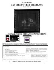
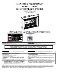
<strong>BurnGreen</strong> REMOTE CONTROL UPGRADE KIT - DXV-35 DEEP TIMBER III<br />
INSTALLATION & OPERATING INSTRUCTIONS<br />
NO. 8503008160510<br />
WARNING<br />
If you do not follow these instructions exactly, a fire or<br />
explosion may result causing property damage,<br />
personal injury or loss of life.<br />
CAUTION: Keep gasoline and other liquids having<br />
flammable vapors away.<br />
WHAT TO DO IF YOU SMELL GAS<br />
• Do not try to light any appliance.<br />
• Do not touch any electrical switch; do not use any<br />
phone in your building.<br />
• Immediately call your gas supplier from a<br />
neighbor's phone. Follow the gas supplier’s<br />
instructions.<br />
• If you cannot reach your gas supplier, call the fire<br />
department.<br />
AVERTISSEMENT. Quiconque ne respecte pas à la<br />
lettre les instructions dans la présente notice risque de<br />
déclencher un incendie ou une explosion entraînant<br />
des dommages, des blessures ou la mort.<br />
ATTENTION. Garder l’essence ou autres liquides<br />
produisant des vapeurs inflammables loin del’appareil.<br />
QUE FAIRE SI VOUS SENTEZ UNE ODEUR DE GAZ<br />
:<br />
• Ne pas tenter d’allumer d’appareil.<br />
• Ne touchez à aucun interrupteur; ne pas vous<br />
servir des téléphones se trouvant dans le bâtiment.<br />
• Appelez immédiatement votre fournisseur de gaz<br />
depuis un voisin. Suivez les instructions du<br />
fournisseur.<br />
• Si vous ne pouvez rejoindre le fournisseur, appelez<br />
le service des incendies.<br />
WARNING<br />
Do NOT use this appliance if any part has been under<br />
water. Immediately call a qualified service technician<br />
to inspect the appliance and to replace any part of the<br />
control system and any gas control, which has been<br />
N’utilisez pas cet appareil s’il a été plongé dans l’eau,<br />
même partiellement. Faites inspecter l’appareil par un<br />
technicien qualifiéet remplacez toute partie du système<br />
de contrôle et toute commande qui ont été plongés<br />
dans l’eau.<br />
WARNING: Improper installation, adjustment,<br />
alteration, service or maintenance can cause injury or<br />
property damage. Refer to this manual. For<br />
assistance or additional information consult a qualified<br />
installer, service agency or the gas supplier.<br />
AVERTISSEMENT : Une installation, un réglage, une<br />
modification, une réparation ou un entretien mal<br />
effectué peut causer des dommages matériels ou des<br />
blessures. Voir la notice de l'utilisateur quiaccompgne<br />
l’appareil. Pour de l’aide oueds renseignements<br />
supplémentaires consultez un installateur un
FOR YOUR SAFETY READ BEFORE LIGHTING<br />
POUR PLUS DE SÉCURITÉ, LIRE AVANTD'ALLUMER<br />
WARNING<br />
Do not operate this appliance with the glass<br />
removed, cracked or broken. A licensed or<br />
qualified person should do replacement of glass.<br />
Attention. Ne pas utiliser l’appareil si le panneau<br />
frontal en verre n’est pas enplace, est craqué ou<br />
brisé. Confiez leremplacement du panneau à<br />
untechnicien agréé.<br />
This appliance must be installed in accordance<br />
with local codes, if any; if none, follow the<br />
National Fuel Gas Code, ANSI Z223.1, or<br />
Canadian Installation Codes, CAN/CGA-B149.<br />
Gas and Propane Installation Code, CSA B149.1<br />
Installer l'appareil selon les codes ou règlements<br />
locaux, ou, en l'absence dételés règlements,<br />
selon les codes d'installation ANSI Z223.1,<br />
National Fuel Gas Code ou CAN/CGA-B149 en<br />
This appliance is only for use with the type(s) of<br />
gas indicated on the rating plate and may be<br />
installed in an aftermarket, permanently located,<br />
manufactured home (USA only) or mobile home,<br />
where not prohibited by local codes. See owner's<br />
manual for details. This appliance is supplied<br />
with a conversion kit.<br />
In the Commonwealth of Massachusetts:<br />
• Installation must be performed by a licensed<br />
plumber or gas fitter;<br />
• A CO detector shall be installed in the room<br />
where the appliance is installed.<br />
Cet appareil doit être utilisé uniquement avec le<br />
type de gaz indiqué sur la plaque signalétique.<br />
Cet appareil peut être installé dans une maison<br />
préfabriquée ou mobile (É.-U. seulement)<br />
installée à demeure si les règlements locaux le<br />
permettent. Voir la notice de l'utilisateur pour plus<br />
de renseignements. Cet appareil ne peut pas<br />
être utilisé avecd'autres gaz sauf si une trousse<br />
deconversion certifiée est fournie.<br />
Attention. Au moment de l’entretiennes<br />
commandes, étiquetez tous les fil savant de les<br />
débrancher. Des erreurs decâblage peuvent<br />
entraîner unfonctionnement inadéquat<br />
etdangereux.<br />
Caution: Label all wires prior to disconnection<br />
when servicing controls. Wiring errors can cause<br />
improper and dangerous operation.<br />
CAUTION: THESE INSTRUCTIONS ARE TO<br />
REMAIN WITH THE HOMEOWNER.
REMOTE CONTROL UPGRAGE KIT -DXV35 DT3<br />
INSTALLATION INSTRUCTIONS<br />
REMOTE CONTROL UPGRADE KIT FEATURES - QUICK REFERENCE INFORMATION<br />
PILOT IGNITION CONTROL: IPI Electronic Ignition of Pilot Flame and main burners from Remote Control.<br />
Rear burner On/Off: Rear Burner On/OFF function from Remote Control.<br />
Flame Height Control: Flame height and heat output can be regulated from Remote Control.<br />
Blower On/Off and Speed Control: Remote Control can initiate blower On when fireplace is cold. Once unit warms up,<br />
Remote Control can regulate blower speeds in six steps. However, if Fireplace has warmed up, blowers will stay ON<br />
regardless of the remote control sending an OFF signal to Fireplace. In these instances, blowers will run at the preset<br />
LOW speed to extract all heat from fireplace. Blowers will turn OFF when unit cools down sufficiently.<br />
NOTE: RHEOSTAT MOUNTED IN COURTESY PANEL TO CONTROL BLOWER SPEED MUST BE ADJUSTED TO<br />
THE LOWEST BLOWER SPEED LEVEL IF THIS REMOTE CONTROL KIT IS INSTALLED.<br />
Accent Light On/OFF Control: Accent Light can be turned ON or OFF from remote control. Accent Light Dimming<br />
cannot be done from Remote Control. An additional Accent Light Dimmer mounted in Fireplace’s Courtesy Panel must be<br />
ON for accent light to function. Accent Light Dimmer mounted in Fireplace control Accent Light Intensity.<br />
Page 3 of 32
REMOTE CONTROL UPGRAGE KIT -DXV35 DT3<br />
INSTALLATION INSTRUCTIONS<br />
Table of Contents<br />
FOR YOUR SAFETY READ BEFORE LIGHTING ................................................................................................................. 2<br />
REMOTE CONTROL UPGRADE KIT FEATURES - QUICK REFERENCE INFORMATION ............................................ 3<br />
PARTS IDENTIFICATION DIAGRAM ..................................................................................................................................... 5<br />
GENERAL INFORMATION ................................................................................................................................................ 6<br />
BEFORE YOU BEGIN ........................................................................................................................................................ 6<br />
AC/DC TRANSFORMER REMOVAL ................................................................................................................................. 7<br />
BATTERY PACK REMOVAL AND RECEIVER INSTALLATION (item #2) ........................................................................ 8<br />
WIRING CONNECTIONS ....................................................................................................................................................... 9<br />
STEP 1: ACCENT LIGHT SYSTEM PLUG HARNESS REMOVAL ................................................................................... 9<br />
STEP 2: FAN CONTROL MODULE INSTALLATION (item #1) ......................................................................................... 9<br />
STEP 3: FAN SYSTEM SECONDARY WIRING INSTALLATION ................................................................................... 11<br />
STEP 4: TURN ON FAN CONTROL MODULE ................................................................................................................ 12<br />
STEP 5: Install Motorized Pressure Regulator (Stepper Motor) ....................................................................................... 13<br />
STEP 6: INSTALLING THE “WIRE HARNESS – RECEIVER CONNECTION” (item #7) .................................................... 14<br />
WIRE HARNESS – RECEIVER CONNECTION (ITEM #7) IDENTIFICATION DIAGRAM ............................................. 15<br />
i. CONNECTION TO REMOTE CONTROL RECEIVER .................................................................................................. 16<br />
ii. CONNECTION TO THE FAN CONTROL MODULE (FCM) ......................................................................................... 16<br />
iii. CONNECTION TO THE MOTORIZED PRESSURE REGULATOR (STEPPER MOTOR) ......................................... 17<br />
iv. Connection to the Rear Burner Solenoid Valve (Split Flow) ....................................................................................... 17<br />
v. Connection to the DC-Supply connector ...................................................................................................................... 18<br />
vi. Connection to the Green colored TPTH terminal and the White Colored TH terminal (TPTH and TH) ...................... 18<br />
TESTING THE MAIN WIRING SYSTEM .......................................................................................................................... 19<br />
BEFORE YOU BEGIN .......................................................................................................................................................... 20<br />
Remote Control Transmitter Functions ............................................................................................................................. 20<br />
REMOTE TRANSMITTER OPERATING INSTRUCTIONS .................................................................................................. 21<br />
TO TURN ON THE APPLIANCE: ..................................................................................................................................... 21<br />
TO TURN OFF THE APPLIANCE. ................................................................................................................................... 21<br />
MANUAL BYPASS OF THE REMOTE SYSTEM ................................................................................................................. 21<br />
TEMPERATURE INDICATOR ( o F or o C) .............................................................................................................................. 22<br />
KEY LOCK FUNCTION ......................................................................................................................................................... 22<br />
LOW BATTERY POWER DETECTION ................................................................................................................................ 22<br />
OPERATING DURING POWER OUTAGES ........................................................................................................................ 23<br />
“FIRST TIME” LIGHTING INSTRUCTIONS .......................................................................................................................... 23<br />
OPERATING DURING POWER OUTAGES .................................................................................................................... 23<br />
NATURAL TO LP GAS CONVERSION INSTRUCTIONS .................................................................................................... 24<br />
ORIFICE SIZES REQUIREMENT: ................................................................................................................................... 24<br />
RECOMMENDED PROCEDURE TO CONVERT THIS FIREPLACE TO BURN LPG .................................................... 24<br />
INSTALLING THE LP PRESSURE REGULATOR ........................................................................................................... 27<br />
INSTALLING THE LP PRESSURE REGULATOR ........................................................................................................... 27<br />
LP GAS PRESSURE REQUIREMENTS .............................................................................................................................. 28<br />
LPG PROPER INPUT RATES .......................................................................................................................................... 28<br />
LEAK TESTING REQUIREMENTS .................................................................................................................................. 28<br />
PILOT FLAME AND MAIN BURNER RELATIONSHIP VERIFICATION .......................................................................... 28<br />
PILOT FLAME LENGTH ADJUSTMENT.......................................................................................................................... 28<br />
CHECKING FOR NORMAL BURNER (S) IGNITION CHARACTERISTICS ................................................................... 29<br />
ATTACHING LPG CONVERSION LABELS AND HIGH ALTITUDE DERATION LABEL ................................................ 29<br />
Page 4 of 32
REMOTE CONTROL UPGRAGE KIT -DXV35 DT3<br />
INSTALLATION INSTRUCTIONS<br />
This instructions set applies to both the NG and LPG Remote Upgrade Kits [#AA-11-01256 & AA-11-01257].<br />
WARNING: THIS REMOTE KIT IS NOT DESIGNED FOR USE WITH OLDER GENERATION DXV35 UNITS. DO NOT<br />
ATTEMPT TO INSTALL THIS REMOTE CONTROL KIT ON YOUR SHOWROOM DISPLAY UNIT IF IT IS OF AN OLDER<br />
GENERATION DXV35TF, DXV35DT1 OR DXV35DT2.<br />
TOOLS REQUIRED<br />
¼” HEX DRIVER & SCREW GUN<br />
LIST OF PARTS INCLUDED<br />
KEY QTY. DESCRIPTION<br />
1 1 FAN CONTROL MODULE W/ HEAT SHIELD<br />
2 1 REMOTE RECEIVER W/ 4X “AA” BATTERIES<br />
3 1 REMOTE TRANSMITTER<br />
4 3 “AAA” BATTERIES (for Transmitter)<br />
5 4 MOTORIZED PRESSURE REGULATOR (LPG OR NG)<br />
6 1 TORX WRENCH (for Pressure Regulator Installation)<br />
7 1 WIRE HARNESS – RECEIVER CONNECTION<br />
8 1 PLUG WIRE HARNESS – Blower System<br />
9 1 THIS INSTRUCTIONS MANUAL<br />
Open this package and identify the parts included in this Remote Control Upgrade Kit. If any parts are missing or<br />
damaged, contact the <strong>Mendota</strong> Service Department.<br />
WARNING: THIS KIT MUST BE INSTALLED BY AN AUTHORIZED AND TRAINED GAS FIREPLACE INSTALLER OR<br />
SERVICE PERSON. INSTALLATION BY A “HOME OWNER” IS PROHIBITED!<br />
PARTS IDENTIFICATION DIAGRAM<br />
8<br />
1<br />
2<br />
9<br />
7<br />
6<br />
5 4<br />
3<br />
Page 5 of 32
REMOTE CONTROL UPGRAGE KIT -DXV35 DT3<br />
INSTALLATION INSTRUCTIONS<br />
INTRODUCTION<br />
WARNING: THIS KIT MUST BE INSTALLED BY AN AUTHORIZED AND TRAINED GAS FIREPLACE INSTALLER OR<br />
SERVICE PERSON. INSTALLATION BY A “HOME OWNER” IS PROHIBITED! THIS KIT IS DESIGNED FOR<br />
INSTALLATION ON DXV35 DT3 MODEL UNITS ONLY. THIS KIT IS NOT COMPATIBLE WITH OLDER GENERATION<br />
DXV35, DXV35TF, DXV35DT1 OR DXV35DT2 MODELS.<br />
GENERAL INFORMATION<br />
This MENDOTA <strong>BurnGreen</strong> Remote Control upgrade kit adds remote control functionality to all features of the DXV35<br />
DT3 Fireplace. This includes Manual, Thermostatic and Smart Thermostat functions, IPI pilot flame ignition and main<br />
burner ignition functions, Flame Height modulation function, Rear Burner On/Off function, Accent Light On/Off function<br />
and Blower speed regulation function.<br />
NOTE: This Remote Kit Will Not Turn The Blower System To Off If The Fireplace Is Hot. The Blower Will Turn Off Only If<br />
The Fireplace Has Cooled Down Close To Room Temperature. This is a feature installed to transfer ALL heat contained<br />
in the Fireplace Body to the living space rather than letting the heat expel out through the exhaust system.<br />
BEFORE YOU BEGIN<br />
CAUTION: MAKE CERTAIN THE PILOT LIGHT IS TURNED OFF AND DISCONNECT THE ELECTRICITY SUPPLY TO<br />
THIS FIREPLACE BEFORE STARTING THIS UPGRADE PROCESS.<br />
Open glass door and remove glass frame and set aside.<br />
Remove two screws that secure courtesy panel to Valve Assembly then slowly pull Courtesy Panel our of Unit<br />
and rotate down to expose rear surface of Courtesy Panel. DO NOT PUT TENSION ON WIRE HARNESSES!<br />
Page 6 of 32
REMOTE CONTROL UPGRAGE KIT -DXV35 DT3<br />
INSTALLATION INSTRUCTIONS<br />
AC/DC TRANSFORMER REMOVAL<br />
Locate AC/DC Transformer on left side of unit. If plugged in Fireplace’s Left Side Outlet, unplug and remove<br />
transformer and discard Transformer or save it in your replacement parts stock.<br />
REMOVE TRANSFORMER; DISCONNECT<br />
TRANSMITTER CONNECTOR AT “DC-SUPPLY”<br />
CONNECTION. DISCARD TRANSFORMER OR SAVE<br />
IT IN YOUR REPLACEMENT PARTS STOCK..<br />
Page 7 of 32
REMOTE CONTROL UPGRAGE KIT -DXV35 DT3<br />
INSTALLATION INSTRUCTIONS<br />
BATTERY PACK REMOVAL AND RECEIVER INSTALLATION (item #2)<br />
Locate Battery Pack and Battery Pack Bracket. Disconnect Wires from Battery Pack and remove Battery Pack<br />
and Battery Pack Bracket. Discard Battery Pack and Battery Pack Bracket.<br />
NOTE: Red and Black Wires connected to Battery will not be used with the Remote Kit. Leave wires intact inside<br />
fireplace but not connected to any other wire harnesses.<br />
Install Receiver. Receiver mounts using the same screws that secured Battery Pack Bracket to Courtesy Panel.<br />
Reuse these screws to<br />
mount Receiver.<br />
Page 8 of 32<br />
NOTE: Battery Compartment<br />
cover with “ON-REMOTE-OFF”<br />
decal shall be on TOP.
REMOTE CONTROL UPGRAGE KIT -DXV35 DT3<br />
INSTALLATION INSTRUCTIONS<br />
WIRING CONNECTIONS<br />
Follow all wiring instructions in the exact order given here. Failure to follow in order will lead to improper wiring<br />
which can lead to damage to the gas valve, rear burner solenoid, fan control module, fan rheostat and remote<br />
receiver. Damage due to improper wiring is not covered under the <strong>Mendota</strong> Warranty Policy.<br />
Follow each step, below, exactly and in the exact order given. Make certain that the Courtesy Panel is removed<br />
and rotated downward to provide access inside the fireplace cavity.<br />
STEP 1: ACCENT LIGHT SYSTEM PLUG HARNESS REMOVAL<br />
Locate Accent Light Harness Plug. Trace the wires from the Accent Light Dimmer to the Plug. This plug is factory<br />
assembled and plugged in to the “FRONT” outlet on the Right Side of the Fireplace.<br />
Unplug the Accent Light Harness from where it is plugged in and pull out towards the front of the unit.<br />
WARNING: DO NOT REMOVE THE OTHER PLUG THAT IS CONNECTED TO THE REAR OUTLET!<br />
STEP 2: FAN CONTROL MODULE INSTALLATION (item #1)<br />
Unwrap and extend the plug harness connected to the Fan Control Module (FCM).<br />
Insert FCM plug inside unit on right side and plug this harness into the same outlet you removed the Accent Light Plug<br />
from.<br />
Plug the Accent Light Plug into the AUX OUT outlet on the Fan Control Module.<br />
REAR<br />
OUTLET<br />
FCM<br />
FRONT<br />
OUTLET<br />
AUX<br />
ACCENT<br />
LIGHT PLUG<br />
TO<br />
ACCENT<br />
LIGHT<br />
LIGHT DIMMER<br />
Page 9 of 32
REMOTE CONTROL UPGRAGE KIT -DXV35 DT3<br />
INSTALLATION INSTRUCTIONS<br />
The FCM sits on the right side against the silver insulation foil wall. Push FCM as far to the right as possible and pull as<br />
far forward as possible. This is a very tight fit. Route the FCM Plug cable carefully. You must provide room above the<br />
FCM for the gas supply line to be routed.<br />
Gas Supply<br />
Line Runs over<br />
Page 10 of 32
REMOTE CONTROL UPGRAGE KIT -DXV35 DT3<br />
INSTALLATION INSTRUCTIONS<br />
STEP 3: FAN SYSTEM SECONDARY WIRING INSTALLATION<br />
Look into the unit cavity behind the gas valve. Locate a loose cable bundle with a label that reads “FCM FAN PLUG<br />
ONLY”. This cable bundle has three wires: White, Black and Green.<br />
Remove the Male connectors that are plugged on the ends of all three wires and discard the loose Male connectors.<br />
Locate item #8 of the shipment you received “PLUG WIRE HARNESS – blower system”.<br />
Connect the color matched ends of the PLUG WIRE HARNES to the ends of the “FCM FAN PLUG ONLY” labeled wire<br />
bundle.<br />
WARNING: CONNECT WHITE TO WHITE, BLACK TO BLACK AND GREEN TO GREEN ONLY! IF YOU DO NOT<br />
MATCH WIRE COLORS IN THIS STEP, YOU WILL CREATE A SHORT CIRCUIT THAT WILL DAMAGE THE FANS,<br />
THE FAN RHEOSTAT, THE FCM AND OTHER COMPONENTS.<br />
Once the connections are made, insert the PLUG WIRE HARNESS into the receptacle in the Fan Control Module (FCM)<br />
labeled ‘FAN”.<br />
IMPORTANT NOTE<br />
RHEOSTAT MOUNTED IN COURTESY PANEL TO CONTROL BLOWER SPEED MUST BE ADJUSTED TO THE<br />
LOWEST BLOWER SPEED LEVELWHEN THIS REMOTE CONTROL KIT IS INSTALLED. IF YOU DO NOT ADJUST<br />
THE RHEOSTAT SPEED TO ITS LOWEST SETTING AND THE RHEOSTAT IS SET AT A HIGHER SPEED, THE<br />
REMOTE CONTROL WILL ONLY REGULATE THE BLOWER SPEED DOWN TO THE SPEED LEVEL THAT THE<br />
RHEOSTAT IS SET AT. TURN THE RHEOSTAT KNOB TO ITS LOWEST SPEED POSITION!<br />
RIGHT SIDE<br />
OUTLETS<br />
BLUE<br />
T-TAPS<br />
RH BLOWER<br />
GROUND<br />
FAN CONTROL<br />
MODULE<br />
LH BLOWER<br />
W HITE<br />
HW H W H W H W<br />
BLACK<br />
FCM FAN<br />
PLUG ONLY<br />
GREEN<br />
FCM FAN PLUG<br />
HARNESS<br />
WHITE<br />
GREEN<br />
BLACK<br />
ACCENT LIGHT<br />
PLUG HARNESS<br />
TO ACCENT<br />
LIGHT HOUSING<br />
HW HW<br />
HW<br />
BLACK<br />
SNAPDISK<br />
BLOWER<br />
RHEOSTAT<br />
LIGHT<br />
DIMMER<br />
RHEOSTAT KNOB MUST BE TURNED TO “LOW”.<br />
ONCE THE REMOTE CONTROL KIT IS INSTALLED,<br />
THIS KNOB HAS NO FUNCTION EXCEPT TO SET<br />
THE LOWEST BLOWER SPEED. IF YOU DO NOT<br />
SET IT TO LOW, THE REMOTE SYSTEM WILL NOT<br />
BE ABLE TO MODULATE THE BLOWER SPEED<br />
BELOW THE SPEED THAT IS SET WTH THIS<br />
RHEOSTAT.<br />
Page 11 of 32
REMOTE CONTROL UPGRAGE KIT -DXV35 DT3<br />
INSTALLATION INSTRUCTIONS<br />
STEP 4: TURN ON FAN CONTROL MODULE<br />
The fan control module has a power switch. Make sure it is in the ON (“-“) position. This switch must remain in the ON<br />
position for the AC components to operate (Accent Light and Blower). This module also supplies low-voltage power for the<br />
fireplace controller. By leaving it in the OFF position, the fireplace will operate off the receiver batteries, greatly<br />
diminishing battery life.<br />
Page 12 of 32
REMOTE CONTROL UPGRAGE KIT -DXV35 DT3<br />
INSTALLATION INSTRUCTIONS<br />
STEP 5: Install Motorized Pressure Regulator (Stepper Motor)<br />
WARNING: READ AND UNDERSTAND ALL INSTRUCTIONS PACKAGED WITH PRESSURE REGULATOR BODY<br />
BEFORE YOU ATTEMPT THE CONVERSION. FAILURE TO FOLLOW ALL INSTRUCTIONS WILL RESULT IN A LEAK<br />
OR OVERFIRING OF THE APPLIANCE AND CAN LEAD TO AN EXPLOSION OR A FIRE HAZARD.<br />
Remove the Courtesy Access Panel mounted behind the lower grill and lay down gently without disconnecting<br />
any wires of internal components. WARNING: DO NOT FORCE. EXCESSIVE FORCE MAY DAMAGE<br />
INTERNAL WIRING COMPONENTS!<br />
Pull out and remove Extension Knob on NG Pressure Regulator and set aside.<br />
Follow Instructions given below directly from SIT Controls. Replace Extension Knob as the final step.<br />
Page 13 of 32
REMOTE CONTROL UPGRAGE KIT -DXV35 DT3<br />
INSTALLATION INSTRUCTIONS<br />
STEP 6: INSTALLING THE “WIRE HARNESS – RECEIVER CONNECTION” (item #7)<br />
A total of 6 different connections must be made for the entire system to operate properly.<br />
i. Connection to the Remote Control Receiver (RECEIVER)<br />
ii. Connection to the Fan Control Module (FCM-COM)<br />
iii. Connection to the Motorized Pressure Regulator (MOTOR)<br />
iv. Connection to the Rear Burner Solenoid Valve (SPLITFLOW)<br />
v. Connection to the DC-Supply connector (DFC-SUPPLY)<br />
vi. Connection to the Green colored TH terminal and the White Colored TPTH terminal (TPTH and TH)<br />
Follow the instructions in the order given. Although there are SIX connections to be made, all six connections are unique<br />
in shape and color and cannot be mistaken. Below, is a general wiring diagram that will help you identify the first four<br />
connections. Connections 5 & 6 are now shown here. Detailed diagrams are provided in the specific sections in this<br />
manual that cover the #5 & #6 connections.<br />
Page 14 of 32
REMOTE CONTROL UPGRAGE KIT -DXV35 DT3<br />
INSTALLATION INSTRUCTIONS<br />
WIRE HARNESS – RECEIVER CONNECTION (ITEM #7) IDENTIFICATION DIAGRAM<br />
The diagram, below, depicts the “Wire Harness – Receiver Connection”. Each end is numbered according to the<br />
installation instructions steps and the identifying labels attached to each end.<br />
iii. MOTOR<br />
ii. FCM-COM<br />
iv. SPLITFLOW<br />
i. RECEIVER<br />
vi. TPTH & TH<br />
V. DFC-SUPPLY<br />
ii. FCM-COM<br />
i. RECEIVER<br />
Page 15 of 32
REMOTE CONTROL UPGRAGE KIT -DXV35 DT3<br />
INSTALLATION INSTRUCTIONS<br />
i. CONNECTION TO REMOTE CONTROL RECEIVER<br />
Connect the white multi-wire connector labeled “RECEIVER” to the port in the rear of the Remote Receiver. Note that the<br />
connectors are keyed so insertion is only allowed if the connectors are oriented correctly. Do not force. If connectors are<br />
aligned properly, they will engage easily. See diagram, below.<br />
RECEIVER<br />
ii. CONNECTION TO THE FAN CONTROL MODULE (FCM)<br />
Locate the COM port in the FCM. Locate the small white connector labeled “FCM-COM”. Note that the connectors are<br />
keyed so insertion is only allowed if the connectors are oriented correctly. Do not force. If connectors are aligned properly,<br />
they will engage easily.<br />
FCM-COM<br />
Page 16 of 32
REMOTE CONTROL UPGRAGE KIT -DXV35 DT3<br />
INSTALLATION INSTRUCTIONS<br />
iii. CONNECTION TO THE MOTORIZED PRESSURE REGULATOR (STEPPER MOTOR)<br />
Locate the ribbon cable connected to the Motorized Pressure Regulator. The connector at the end of this cable connects<br />
to the connector labeled “MOTOR” that is part of the Receiver Harness. The connectors can mate only one way. Do not<br />
force.<br />
STEPPER<br />
MOTOR<br />
CONNECTORS<br />
iv. Connection to the Rear Burner Solenoid Valve (Split Flow)<br />
Locate the loose connector at the end of the Pink and Blue wires that are attached to the Rear Burner Solenoid Valve<br />
(Split Flow). Locate the connector labeled “SPLIT FLOW” in the Receiver Harness. Attach these two connectors together.<br />
Make certain pins in the male connector are not bent before connecting to the female connector.<br />
SPLITFLOW<br />
(SPLIT FLOW) REAR<br />
BURNER SOLENOID<br />
CONNECTORS<br />
Page 17 of 32
REMOTE CONTROL UPGRAGE KIT -DXV35 DT3<br />
INSTALLATION INSTRUCTIONS<br />
v. Connection to the DC-Supply connector<br />
See diagram, below, that identifies the connectors on<br />
the left side of the Courtesy panel’s back-side..<br />
Identify the “DC- SUPPLY” CONNECTOR from which<br />
you disconnected the AC/DC Transformer. Identify the<br />
matching connector that is part of the “Receiver<br />
Harness”. Connect the Male AC/DC adapter to the<br />
connector labeled “DC-SUPPLY”.<br />
DFC-SUPPLY<br />
vi. Connection to the Green colored TH terminal and the White Colored TPTH terminal (TPTH and TH)<br />
Locate the ON/OFF Switch on the left side of Courtesy Panel. Identify the short jumper wires that are connected to the<br />
switch. Identify the Green and White colored wires with label “ON-OFF” that connect to these two short jumper wires.<br />
Disconnect the White and Green wires connected to the short jumper wires. Identify the Green Wire (part of the Receiver<br />
Harness) labeled “TH”. Connect this wire to the Green wire labeled “ON-OFF”. Identify the White Wire (part of the<br />
Receiver Harness) labeled “TPTH”. Connect this wire to the White wire labeled “ON-OFF”.<br />
ON-OFF<br />
1. DISCONNECT “ON-OFF” WIRES FROM<br />
ON/OFF SWITCH WIRE JUMPERS.<br />
2. CONNECT “TH” WIRE TO GREEN “ON-<br />
OFF” WIRE<br />
3. CONNECT “TPTH” WIRE TO WHITE<br />
“ON-OFF” WIRE.<br />
TPTH<br />
TH<br />
WARNING – GREEN WIRE (TH) MUST<br />
MATE WITH GREEN WIRE IN ON-OFF<br />
CIRCUIT. WHITE WIRE (TPTH) MUST<br />
MATE WITHWHITE WIRE IN ON-OFF<br />
CIRCUIT. IF YOU MISMATCH COLORS,<br />
YOUR SYSTEM WILL NOT FUNCTION!<br />
Page 18 of 32
REMOTE CONTROL UPGRAGE KIT -DXV35 DT3<br />
INSTALLATION INSTRUCTIONS<br />
Connections of all new wire connector ends are now complete. Double check all connections and confirm that all<br />
connections are secure and that wires are routed properly so no wires will be pinched when replacing the Courtesy Panel.<br />
DO NOT REPLACE THE GLASS FRAME AT THIS TIME.<br />
TESTING THE MAIN WIRING SYSTEM<br />
1. Turn ON the electricity to Fireplace.<br />
2. Turn ON the gas supply to Fireplace.<br />
3. Toggle PILOT LIGHT ON/OFF SWITCH to “Standing Pilot” position. You should hear and visibly see sparking at<br />
the pilot light. After the air in the gas line has bled through, the pilot light will ignite and remain lit.<br />
4. Slide Remote Receiver Slider Switch to ON. Burners should ignite. Slide Remote Receiver Slider Switch to<br />
“REMOTE” position once burners ignite. DO NOT LEAVE BURNERS ON FOR MORE THAN 30 SECONDS.<br />
5. Install Glass Frame on Fireplace and secure with two spring latched located on top of firebox.<br />
6. Insert “AAA” Batteries in Remote Transmitter.<br />
7. Press “PRG” button on Remote Receiver. You will hear a “beep”.<br />
8. Press any button on the Remote Transmitter. You will hear “beep, beep, beep” indicating that the remote<br />
transmitter and remote receiver are synchronized.<br />
9. Test Blower Functions and Accent Light Functions in “MANUAL THERMOSTAT MODE”. See REMOTE<br />
TRANSMITTER OPERATING INSTRUCTIONS section of this manual.<br />
Once you have verified that all functions operate properly, reinstall Courtesy Panel carefully. Make certain no wires or<br />
connectors are pinched between metal parts.<br />
Page 19 of 32
REMOTE CONTROL UPGRAGE KIT -DXV35 DT3<br />
INSTALLATION INSTRUCTIONS<br />
BEFORE YOU BEGIN<br />
Read this entire manual before you use your new fireplace (especially the section “Safety Precautions” on page 2).<br />
Failure to follow the instructions may result in property damage, bodily injury, or even death.<br />
Remote Control Transmitter Functions<br />
NOTE: The Wall Receiver will “beep” once every time<br />
a Remote Transmitter Key is pressed, signaling that<br />
the command has been received.<br />
Identify the four function buttons on the Remote<br />
Transmitter:<br />
1. ON/OFF KEY: This button<br />
turns the system ON or OFF.<br />
When this button is pressed<br />
and the system is OFF, the<br />
pilot light will stay ON if the “Standing Pilot<br />
Switch” is in the ON position.<br />
2. THERMOSTAT KEY: This button, when pressed after the ON/OFF KEY is pressed and the<br />
system is ON, will allow the selection of three modes: Manual Operation, Normal Thermostat<br />
and Smart Thermostat.<br />
a. Manual Mode: In this mode, the room temperature is ignored and the fireplace can be turned ON indefinitely.<br />
The room temperature rise has no effect on this mode. All other functions such as flame height control,<br />
secondary burner On/OFF control and Accent Light ON/OFF controls will be manually controllable. Fan speed<br />
will be manually controllable always but if unit is<br />
ON<br />
SMART<br />
hot, fan cannot be turned to OFF.<br />
OFF<br />
b. Normal Thermostat: In this mode, the fireplace<br />
will stay functioning until the room temperature<br />
increases 1 o F above the Set Point Temperature.<br />
To increase the Set Point Temperature, Press the<br />
UP button until the desired temperature is<br />
displayed in the SET POINT TEMPERATURE<br />
window. The fan will turn on 5 minutes after<br />
fireplace startup or when fireplace warms up and<br />
will turn off 12-1/2 minutes after the flames turn off<br />
or when unit cools down, in this mode. The flame<br />
height can be adjusted while the fireplace is<br />
functioning, fan speed can be adjusted after 5<br />
minutes of startup. Secondary burner can be<br />
turned On or Off at any time after startup. The<br />
Accent Light can be turned on or off any time after<br />
startup.<br />
c. Smart Thermostat: In this mode, all other functions except the flame height adjustment are allowed. Manual<br />
flame height adjustment is not allowed in this mode. The Smart Thermostat function adjusts the flame height<br />
in accordance to the difference between the set point temperature and the actual room temperature. As the<br />
room temperature gets closer to the set point temperature, the Smart Function automatically modulates the<br />
flame down.<br />
UP/DOWN KEY: This key is used to increase or decrease the Set Point Temperatures, Flame Height<br />
and Fan Speed and to toggle between Accent Light ON/OFF and Secondary Burner ON/OFF.<br />
MODE SELECTION KEY: This key is used to toggle between the various function icons:<br />
Flame Height, Fan Speed, Accent Light and Secondary Burner.<br />
MAX<br />
F<br />
OFF<br />
76°<br />
ON SMART<br />
76° 76° F F<br />
Hi<br />
MANUAL<br />
MODE<br />
MAX<br />
Hi<br />
NORMAL<br />
THERMOSTAT<br />
68<br />
SMART<br />
MODE<br />
Page 20 of 32
REMOTE CONTROL UPGRAGE KIT -DXV35 DT3<br />
INSTALLATION INSTRUCTIONS<br />
REMOTE TRANSMITTER OPERATING INSTRUCTIONS<br />
TO TURN ON THE APPLIANCE:<br />
1. Press the ON/OFF button. The transmitter display will show all active icons on the screen.<br />
2. Select the Thermostat Mode by pressing the Thermostat Key: OFF (meaning Manual<br />
Mode), ON (meaning normal Thermostat) or Smart (meaning Smart Mode).<br />
a. In OFF (Manual Mode), the appliance will ignite and start on HI.<br />
b. In ON (Normal Thermostat Mode), the appliance will only ignite if the Set Temperature<br />
is greater than the Room Temperature.<br />
c. In SMART (Smart Mode), the appliance will only ignite if the Set Temperature is greater<br />
than the Room Temperature.<br />
TO TURN OFF THE APPLIANCE, press the ON/OFF button.<br />
MODE KEY Pressing the MODE KEY toggles between the<br />
various available functions: Flame Height, Fan Speed, Aux<br />
(Accent Light) On/Off and Secondary Burner On/Off.<br />
Flame Height: 6 flame height Levels are available. While the Flame<br />
Height Icon is displayed, pressing the Up or Down button<br />
once will increase or decrease the flame height by 1 of 6<br />
increments. If the flame height is at Level 1 and the Down<br />
button is pressed, all burners will turn OFF. If in IPI mode,<br />
the pilot light will also extinguish. If in Standing Pilot Mode,<br />
the pilot light will remain ON. Note: If in SMART model, the<br />
flame height function is not available for manual adjustment. In SMART<br />
mode, the flame height regulates automatically.<br />
Fan Speed Control: The fan speed can be adjusted through six (6)<br />
speeds and OFF. To activate this function, press the MODE<br />
Key to index to the fan control icon. Use the UP/Down Arrow<br />
Key to turn ON, OFF or adjust the fan speed. A single “beep”<br />
will confirm reception of the command. The Fan will continue<br />
to run if the unit is warm until unit cools down.<br />
Aux (Accent-Light): This function controls the <strong>Mendota</strong> Accent Light<br />
function. Pressing the UP key in this mode will TURN ON the Accent<br />
Light and Pressing the DOWN key will TURN OFF the Accent<br />
Light. A single “beep” will confirm reception of the command.<br />
Note: The Accent Light Dimmer control is located adjacent to<br />
the Remote Receiver. Turn the Dimmer Control Knob to dim or brighten the Accent Light. Once you set your<br />
desired brightness level, you may use the AUX function to turn the Accent Light On or Off at that preset level.<br />
Secondary Burner: This function controls the Secondary Burner’s ON/OFF<br />
feature. Pressing the UP Key in this mode will TURN ON the<br />
Secondary Burner and Pressing the DOWN Key will TURN OFF the<br />
Secondary Burner. The flame level will not change when you turn the<br />
Secondary Burner On or Off. The flame level can only be changed in<br />
the Flame Level mode.<br />
MANUAL BYPASS OF THE REMOTE SYSTEM<br />
If the remote transmitter is misplaced or lost, the appliance can be turned on manually by sliding the<br />
three position slider switch on the wall receiver to the ON position. This will bypass the remote<br />
Page 21 of 32
REMOTE CONTROL UPGRAGE KIT -DXV35 DT3<br />
INSTALLATION INSTRUCTIONS<br />
control feature of the system and the appliance’s main burner will turn on. The fan will run at its maximum speed and the<br />
Accent Light may turn on.<br />
To turn off the appliance, if the remote control is misplaced or lost, slide the three position slider switch on the wall<br />
receiver to the OFF Position.<br />
TEMPERATURE INDICATOR ( o F or o C)<br />
1. Press the ON/OFF Key and Turn Off the Fireplace.<br />
2. Simultaneously, Press both the MODE Key and the Thermostat<br />
Key.<br />
3. Look at the LCD display to verify that your desired indicator ( o F or<br />
o C) is being displayed. If not, repeat step 2.<br />
KEY LOCK FUNCTION<br />
To prevent unsupervised children from operating the fireplace, a KEY LOCK function is<br />
provided with this remote control system. To activate the KEY LOCK function,<br />
simultaneously press the “MODE KEY” and the “UP KEY”. To deactivate the KEY LOCK<br />
function, simultaneously press the “MODE KEY” and the “UP KEY”.<br />
During KEY LOCK mode, none of the Keys will function. You must DEACTIVATE the<br />
system before you can use the Remote Transmitter.<br />
LOW BATTERY POWER DETECTION<br />
1. Transmitter Batteries: The life span of the remote control transmitter batteries depends<br />
on various factors: quality of the batteries used, the number of ignitions of the appliance,<br />
the number of changes to the room thermostat set point, etc. When the Transmitter<br />
batteries are low, a Battery Icon will appear on the LCD display of the Transmitter before<br />
all battery power is lost. When the batteries are replaced, this icon will disappear.<br />
2. Receiver Batteries: The life span of the receiver batteries depend on the quality of the<br />
batteries used and how long the batteries have been installed in the receiver. These batteries are only utilized during<br />
power outages. Replace these batteries every heating season even if you have not experienced any power outages.<br />
Batteries drain slowly even when not in use. This is a normal characteristic of all batteries.<br />
Page 22 of 32
REMOTE CONTROL UPGRAGE KIT -DXV35 DT3<br />
INSTALLATION INSTRUCTIONS<br />
OPERATING DURING POWER OUTAGES<br />
This electronic ignition system utilizes the supplied 110VAC power when it is available for all functions of this system. If<br />
the AC power is interrupted during a power outage, this system utilizes the batteries (installed in the Wall Receiver) as<br />
back-up batteries. During the power outage, the appliance’s burners will function. In addition, Flame Height adjustment<br />
and Secondary Burner ON/OFF functions will be available. The Fan and Accent Light, which are wholly dependent on<br />
110VAC power, will not function.<br />
This appliance is designed and tested to be operated during power outages. The overall efficiency of this appliance will be<br />
reduced by approximately 5% when the blower function is disabled during the power outage period.<br />
“FIRST TIME” LIGHTING INSTRUCTIONS<br />
IMPORTANT: Be sure all items on "INSTALLATION CHECK OFF LIST" in the Installation Manual have been completed!<br />
CAUTION: If the pilot goes out, be sure to wait a minimum of five minutes before attempting to relight the pilot.<br />
Make certain that any manual gas supply shut-off valves located upstream of fireplace are open.<br />
Make certain that 120VAC power is connected [and ON] to the electrical junction box on the left side of unit.<br />
Insert Batteries in the Battery Holder if not already installed at the factory. Note the polarity of batteries and insert as<br />
indicated on the battery compartment covers.<br />
For the “First Time Lighting”, Remove the Glass Door. This is required to purge the gas line of air and to inspect the<br />
pilot lighting spark.<br />
Locate the “Standing Pilot ON/OFF Switch”. Toggle “Standing Pilot ON/OFF Switch” to “ON”. You will hear a series<br />
of clicks and after a few seconds, you will hear sparking at the pilot spark electrode. Visually inspect the spark at the<br />
pilot hood and verify that the spark jumps from the spark electrode to the pilot hood.<br />
Allow adequate time for the air in the gas-line to purge. The control system will stop sparking after 30 seconds if the<br />
pilot light does not light. After a 30 second delay the control system will start sparking again for 30 seconds more. If<br />
the pilot light does not light after the third 30 second spark event, the system will enter “Lock-out” mode. To unlock<br />
from “Lock-out” mode, toggle “Standing Pilot ON/OFF Switch to “OFF” and toggle Main ON/OFF Switch to “ON”, wait<br />
30 seconds and toggle Main ON/OFF Switch to OFF. Toggle “Standing Pilot ON/OFF Switch to ON. Repeat this<br />
sequence until the pilot flame lights and the pilot is burning steadily.<br />
LOCK OUT MODE: If the pilot light does not light after the third 30 second spark event, the system will enter “Lockout”<br />
mode. To unlock from “Lock-out” mode, toggle “Standing Pilot ON/OFF Switch to “OFF” and toggle Main ON/OFF<br />
Switch to “ON” (the sparking will start again); wait 30 seconds and toggle Main ON/OFF Switch to OFF. This will reset<br />
the system.<br />
Once the pilot flame is lit and well-established, close glass door. WARNING: NEVER IGNITE MAIN BURNERS WITH<br />
GLASS DOOR REMOVED OR OPEN. Doing so will lead to damage to pilot flame sensor wire and spark electrode<br />
wire leads.<br />
Toggle Main Burners ON/OFF Switch to “ON”. All burners should ignite and run at “high-fire”. If rear burner does not turn<br />
ON, toggle Rear Burner ON/OFF Switch to ON. After 15 seconds, Toggle Main Burners ON/OFF Switch to OFF. Burner<br />
Flames will extinguish.<br />
Perform gas inlet and outlet pressure tests and leak tests on field installed gas fittings and factory installed fittings in the<br />
gas valve compartment, at this time. Note: Burners must be ON to check outlet pressures and to leak test gas train fittings<br />
upstream of main gas valve.<br />
Backup Batteries: The life span of the backup batteries depends on the quality of the batteries used and how<br />
long the batteries have been installed in the wall receiver. These batteries are utilized during power outages.<br />
Replace these batteries every heating season. Batteries drain slowly even when not in use. This is a normal<br />
characteristic of all batteries.<br />
OPERATING DURING POWER OUTAGES<br />
This electronic ignition system utilizes the supplied 110VAC power when it is available for all functions of this system. If<br />
the AC power is interrupted during a power outage, this system utilizes the batteries (installed in the Wall Receiver) as<br />
back-up batteries. During the power outage, the appliance’s burners will function. In addition, Flame Height adjustment<br />
and Secondary Burner ON/OFF functions will be available. The Fan and Accent Light which are wholly dependent on<br />
110VAC power, will not function.<br />
Page 23 of 32
REMOTE CONTROL UPGRAGE KIT -DXV35 DT3<br />
INSTALLATION INSTRUCTIONS<br />
NATURAL TO LP GAS CONVERSION INSTRUCTIONS<br />
Kit # HA-30-00501 <strong>Mendota</strong> Model DXV35 DT3<br />
This conversion kit shall be installed by a qualified service agency<br />
in accordance with the manufacturer’s instructions and all<br />
applicable codes and requirements of the authority having<br />
jurisdiction. If the information in these instructions is not followed<br />
exactly, a fire, explosion or production of carbon monoxide may<br />
result causing property damage, personal injury or loss of life. The<br />
qualified service agency is responsible for the proper installation of<br />
this kit. The installation is not proper and complete until the<br />
operation of the converted appliance is checked as specified in the<br />
owner instructions supplied with the kit.<br />
Caution: The electrical supply to the fireplace must be turned off<br />
prior to performing the conversion. The gas supply must be shut<br />
off prior to disconnecting the electrical power.<br />
ORIFICE SIZES REQUIREMENT:<br />
A Natural Gas to LPG conversion kit #HA-30-00501 is included<br />
with this fireplace insert.<br />
MANUAL<br />
LP Pressure<br />
Regulator<br />
[10.0-6.4"WC]<br />
# 0.907.011<br />
Burner Orifice<br />
#65-14-00364<br />
[3/64"DRILL]<br />
364<br />
364<br />
LP Pilot Orifice<br />
[#05-04-00052]<br />
[#977.168]<br />
LP Conversion Kit # HA-30-00501 contains the following parts: One Motorized LP Pressure Regulator #907.012, One LP<br />
Pilot Orifice Thimble #977.168, and two Cap Orifices #65-14-00364(drill #3/64”) and an L-shaped Torx wrench.<br />
RECOMMENDED PROCEDURE TO CONVERT THIS FIREPLACE TO BURN LPG<br />
This Fireplace Insert arrives from the factory ready to burn Natural Gas. If you intend to burn LPG, it is highly<br />
recommended that you convert this fireplace and its Pressure Regulator, Pilot Orifice Thimble and Burner Orifices prior to<br />
placing this fireplace in its fireplace cavity.<br />
See diagrams, on this page, and follow these instructions to prepare this fireplace for conversion to LPG.<br />
Using a ¼” Hex Driver, remove 2 screws that secure the Rear and Front burners to the Burner Airbox.<br />
Lift Up and remove Front Burner.<br />
Loosen Front Burner Air Shutter Screw and rotate air shutter open ¼” minimum. Set burner aside.<br />
Slide Rear Burner to the right about 2” and lift up and remove from Firebox.<br />
REAR BURNER<br />
BURNERS MOUNTING<br />
SCREWS<br />
FRONT BURNER<br />
Page 24 of 32
REMOTE CONTROL UPGRAGE KIT -DXV35 DT3<br />
INSTALLATION INSTRUCTIONS<br />
1. Using a ½” deep well socket wrench, remove Front and Rear Orifices.<br />
2. Thread a new 3/64” drilled orifice to both Front and Rear Orifice mounting brass fittings. Tighten down orifices.<br />
3. Install pilot orifice thimble ##977.168 see Figure below for location. To remove Pilot Hood, use a screw driver to<br />
pry open the Wire Clip that is located at the base of the Pilot Hood. Pull Upward and remove pilot hood. Use an<br />
Alan wrench to remove NG Pilot Orifice. (Pilot orifice thimble is located inside pilot hood base).<br />
4. Install LP Pilot Orifice. Tighten down using an Alan wrench. Replace Wire Clip in its original position.<br />
5. Push Pilot Hood down into base until it snaps in place.<br />
DETAIL C<br />
Pull Pilot Hood UP<br />
and lift UP off the base.<br />
REAR<br />
ORIFICE<br />
Use an Alan Wrench<br />
To loosen and remove<br />
NG Pilot Orifice. Install<br />
LP Pilot Orifice, Tighten<br />
Down.<br />
FRONT<br />
ORIFICE<br />
WIRE<br />
CLIP.<br />
DETAIL D<br />
REAR<br />
BURNER<br />
PILOT LIGHT<br />
HOOD<br />
FRONT<br />
BURNER<br />
Page 25 of 32
REMOTE CONTROL UPGRAGE KIT -DXV35 DT3<br />
INSTALLATION INSTRUCTIONS<br />
Before reinstalling burners, loosen the screw that secures the rotary air shutter on the Front Burner. Rotate the air<br />
shutter open to ¼” minimum.<br />
Install both rear and front<br />
burners in their original<br />
locations and positions and<br />
secure down using screws you<br />
removed earlier.<br />
NOTE: The recommended air<br />
shutter setting are ¼” min For<br />
LPG and 1/8” min for NG.<br />
LOOSEN SCREW<br />
ROTATE SHUTTER OPEN<br />
-1/4" M INIM UM -<br />
FRONT BURNER SHUTTER ADJUSTMENT<br />
Make certain front burner is running parallel to front face of unit positioned properly so that the pilot light hood<br />
pointing to the left is pointed properly towards the burner’s flame propagation ports.<br />
Make certain Rear Burner is positioned properly so that the pilot light hood pointing to the left is pointed properly<br />
towards the burner’s flame propagation holes.<br />
REAR<br />
BURNER<br />
PILOT LIGHT FLAMES<br />
MUST OVERLAP<br />
BURNER PORTS.<br />
FRONT<br />
BURNER<br />
Page 26 of 32
REMOTE CONTROL UPGRAGE KIT -DXV35 DT3<br />
INSTALLATION INSTRUCTIONS<br />
INSTALLING THE LP PRESSURE REGULATOR<br />
WARNING: READ AND UNDERSTAND ALL INSTRUCTIONS PACKAGED WITH LP PRESSURE REGULATOR BODY<br />
BEFORE YOU ATTEMPT THE CONVERSION. FAILURE TO FOLLOW ALL INSTRUCTIONS WILL RESULT IN A LEAK<br />
OR OVERFIRING OF THE APPLIANCE AND CAN LEAD TO AN EXPLOSION OR A FIRE HAZARD.<br />
Remove the Courtesy Access Panel mounted behind the lower grill and lay down gently without disconnecting<br />
any wires of internal components. WARNING: DO NOT FORCE. EXCESSIVE FORCE MAY DAMAGE<br />
INTERNAL WIRING COMPONENTS!<br />
Pull out and remove Extension Knob on NG Pressure Regulator and set aside.<br />
Follow Instructions given below directly from SIT Controls. Replace Extension Knob as the final step.<br />
Page 27 of 32
REMOTE CONTROL UPGRAGE KIT -DXV35 DT3<br />
INSTALLATION INSTRUCTIONS<br />
LP GAS PRESSURE REQUIREMENTS<br />
Inlet and manifold gas pressure checking taps are located on gas valve. These ports are only accessible from the outer<br />
left side of the fireplace. A qualified installer shall take pressure measurements at these ports to verify and set the correct<br />
gas pressures during the LP Kit installation and before fascia materials are installed over the front of this fireplace.<br />
Manifold pressure must be taken at the “MANIFOLD PRESSURE" tap and inlet pressure at the "INLET PRESSURE" tap<br />
with the burner operating by a qualified installer.<br />
DESIRED<br />
INLET<br />
PRESSURE<br />
L.P. GAS 11.0" W.C.<br />
(2.75 kPa)<br />
MINIMUM<br />
INLET<br />
PRESSURE<br />
11" W.C.<br />
(2.75 kPa)<br />
MAXIMUM<br />
INLET<br />
PRESSURE<br />
13.0" W.C.<br />
(3.24 kPa)<br />
MANIFOLD<br />
OUTLET<br />
PRESSURE<br />
10.0" W.C.<br />
(2.5 kPa)<br />
AIR SHUTTER<br />
POSITION<br />
1/4" OPEN<br />
MIN.<br />
(5 mm)<br />
REGULATE THE FLAME HEIGHT TO "HIGH" POSITION. OUTLET GAS PRESSURES MAY VARY PLUS OR MINUS<br />
5%.<br />
LPG PROPER INPUT RATES<br />
With the proper orifices installed, as specified above,<br />
this fireplace utilizing LP Gas will have a maximum<br />
input rate of 31,000 Btu/Hr.<br />
LEAK TESTING REQUIREMENTS<br />
Prior to completing the conversion process, check for<br />
gas leaks with soap and water solution at all plumbing<br />
joints prior to placing this appliance into operation. It<br />
is recommended that all gas-plumbing joints, factory<br />
installed and field installed are checked for leaks.<br />
OUTLET TAP<br />
INLET TAP<br />
PILOT FLAME AND MAIN BURNER RELATIONSHIP VERIFICATION<br />
Figure 1: Pressure Test Port<br />
Prior to completing the conversion process, the qualified service technician must, light the pilot light and verify the<br />
relationship between the pilot light flames and the main burners. The pilot light flames directed towards the propagation<br />
ports on the rear and front burner must overlap the propagation ports on the burners. The pilot light flames must be a<br />
minimum of ¾” long and must overlap the propagation ports on both the rear and front burners as shown in the diagram,<br />
below. Verify that the burner tubes ignite quickly and the burner flames propagate smoothly along the entire length of the<br />
burners.<br />
PILOT FLAME LENGTH ADJUSTMENT<br />
If the pilot light flame length is too short and the system does<br />
not maintain a standing pilot, a qualified installer may increase<br />
the length of the pilot light flames to meet the two<br />
requirements: Minimum pilot light length to maintain a<br />
standing pilot light and the pilot light flames must be long<br />
enough to overlap the front and rear burner ports, 1 inch long<br />
minimum.<br />
REAR<br />
BURNER<br />
1" MIN.<br />
PILOT LIGHT FLAMES<br />
MUST OVERLAP<br />
BURNER PORTS.<br />
FRONT<br />
BURNER<br />
Page 28 of 32
REMOTE CONTROL UPGRAGE KIT -DXV35 DT3<br />
INSTALLATION INSTRUCTIONS<br />
CHECKING FOR NORMAL BURNER (S) IGNITION CHARACTERISTICS<br />
Once the conversion to LPG and all the above steps have been completed, light the main burners.<br />
Turn Gas Dial counterclockwise to "ON" then set Thermostat or push Main Burner ON/OFF switch to turn on burners.<br />
Main burner should now light IMMEDIATELY and flame should not "lift" off burner. If there is any delay in ignition or if<br />
flame is "lifting off" burner, turn off burner and carefully check for proper installation of logs/coals, vent system and proper<br />
pilot flame impingement on burner and thermopile. Logs or coals must not block pilot flame or main burner flame. Vent<br />
system must be leak proof.<br />
WARNING<br />
DO NOT PROCEED WITH OPERATION OF THIS FIREPLACE<br />
UNLESS BURNER "CYCLES" ON/OFF WITHOUT DELAYS!<br />
ATTACHING LPG CONVERSION LABELS AND HIGH ALTITUDE DERATION LABEL<br />
Two printed informational labels are included with the LPG Conversion Kit. Attach these two labels to the rear surface of<br />
this insert adjacent to the Serial Number Plate. If you are derating this appliance at a high altitude, also attach the High<br />
Altitude Deration Label, supplied in the Owner’s Manual Packet, to this same surface adjacent to other labels.<br />
Prior to attaching the labels, fill in all the information that is requested in these labels.<br />
For installations from 610-1370 meters (2000-4500 ft.) the orifice sizes (DMS) for natural and propane gas are<br />
_#45R/#49F_ and _#55”R/#3/64”F_, respectively. See data plate for additional information. For high altitude<br />
installations consult the local gas distributor or the authority having jurisdiction for proper rating methods. If the<br />
installer must convert the unit to adjust for varying altitudes, the information sticker must be filled out by the installer<br />
and adhered to the appliance at the time of conversion."<br />
«Cet appareil est equipé pour des altitudes compries entre 0 et 2000 pieds (0-610 m) seulement»<br />
This appliance has been converted for use at an altitude of ______________<br />
Orifice size _______________ Manifold Pressure ________________<br />
Input (Btu/h) _______________ Fuel Type _______________________<br />
Date of conversion _________ Converted by _____________________<br />
«Cet appreeil a été converti au ____<br />
Injecteur ________<br />
Pression à la tubulure d'alimentation _____________<br />
Déoit calorifique ______________<br />
GAS LEAK TEST REQUIREMENT: It is the responsibility of the installer/service person to assure that each and every<br />
gas connection and supply tubing that are a part of this fireplace are leak proof. The qualified/ certified individual<br />
connecting the gas supply line, performing pressure tests or performing any service to this fireplace is required to perform<br />
a THOROUGH LEAK TEST on ALL gas fittings that are a part of this appliance or the gas supply line connection using<br />
soap-water solution or a calibrated combustible gas detector. Failure to perform this leak test may lead to a house fire<br />
and/or an explosion. <strong>Mendota</strong> is not responsible for any damages due to an Installer’s failure to conduct a leak test and<br />
verify that all connections and supply lines are leak proof.<br />
WARNING: Do not operate appliances with glass front removed, cracked, or broken. Replacement of glass should be<br />
done a licensed or qualified service person.<br />
Note: Consult the local or national installation code(s) to assure that adequate combustion and ventilation air is available.<br />
WARNING: It is of the utmost importance that the correct burner orifices be installed for both<br />
the rear and front burners.<br />
Page 29 of 32
REMOTE CONTROL UPGRAGE KIT -DXV35 DT3<br />
INSTALLATION INSTRUCTIONS<br />
NOTES<br />
Page 30 of 32
REMOTE CONTROL UPGRAGE KIT -DXV35 DT3<br />
INSTALLATION INSTRUCTIONS<br />
NOTES<br />
Page 31 of 32
REMOTE CONTROL UPGRAGE KIT -DXV35 DT3<br />
INSTALLATION INSTRUCTIONS<br />
Johnson Gas Appliance Company<br />
520 E Avenue N.W. - Cedar Rapids, IA 52405<br />
<strong>Mendota</strong> Hearth Division<br />
WEBPAGE: www.johnsongas.com or www.mendotahearth.com<br />
Document #85-03-00816<br />
Page 32 of 32