2011 SEFA Desk Reference - Scientific Equipment and Furniture ...
2011 SEFA Desk Reference - Scientific Equipment and Furniture ...
2011 SEFA Desk Reference - Scientific Equipment and Furniture ...

You also want an ePaper? Increase the reach of your titles
YUMPU automatically turns print PDFs into web optimized ePapers that Google loves.
<strong>Scientific</strong> <strong>Equipment</strong> & <strong>Furniture</strong> Association<br />
<strong>2011</strong> <strong>SEFA</strong> <strong>Desk</strong> <strong>Reference</strong><br />
First Edition<br />
<strong>SEFA</strong> SPELLS SAFE<br />
1
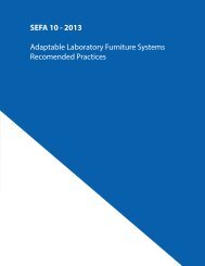
<strong>SEFA</strong> 10 - <strong>2011</strong><br />
Adaptable Laboratory <strong>Furniture</strong> Systems<br />
Recomended Practices<br />
3
Table of Contents<br />
Sub-committee Members<br />
Forword<br />
SECTIONS<br />
1.0 Scope<br />
2.0 Purpose<br />
3.0 Definitions<br />
3.1 Adaptable Laboratory Casework Defined<br />
3.2 Characteristics of Adaptable Casework<br />
Systems<br />
3.3 Glossary of Terms<br />
3.4 Codes <strong>and</strong> St<strong>and</strong>ards<br />
4.0 Classifying Adaptable Laboratory <strong>Furniture</strong><br />
Systems<br />
4.1 Description of Classes<br />
5.0 Adaptable Laboratory <strong>Furniture</strong> System<br />
Class Data Sheets<br />
5.1 Class1<br />
5.2 Class 2<br />
5.3 Class 3<br />
5.4 Class 4<br />
5.5 Class 5<br />
5.6 Class 6<br />
5.7 Class 7<br />
5.8 Class 8<br />
6.0 Test Criteria<br />
6.1 Purpose of Test<br />
6.2 Description of Test Bench<br />
6.3 Live Load<br />
6.3.1 Each Shelf<br />
6.3.2 Worksurface<br />
6.4 Strength Test Configuration 1<br />
6.4.1 Test Procedure<br />
6.4.2 Acceptance Criteria<br />
6.4.3 Test Procedure Continued<br />
6.4.4 Acceptance Criteria<br />
6.5 Stability Test Anchored Units<br />
6.5.1 Test Procedure<br />
6.5.2 Acceptance Level<br />
6.6 Stability Test Free St<strong>and</strong>ing Units<br />
6.6.1 Test Procedure<br />
6.6.2 Acceptance Leval<br />
6.7 Strength Test Configuration 2<br />
6.7.1 Test Procedure<br />
6.7.2 Acceptance Criteria<br />
6.8 Stability Test Anchored Units<br />
6.8.1 Test Procedure<br />
6.8.2. Acceptance Level<br />
6.9 Stability Test Free St<strong>and</strong>ing Units<br />
6.9.1 Test Procedure<br />
6.9.2. Acceptance Level<br />
6.10 Strength Test Configuration 3<br />
6.10.1 Test Procedure<br />
6.10.2. Acceptance Criteria<br />
6.11 Stability Test Anchored Units<br />
6.11.1 Test Procedure<br />
6.11.2. Acceptance Level<br />
6.12 Stability Test Free St<strong>and</strong>ing Units<br />
6.12.1 Test Procedure<br />
6.12.2. Acceptance Level<br />
6.13 Strength Test Configuration 4<br />
6.13.1 Test Procedure<br />
6.13.2. Acceptance Criteria<br />
6.14 Stability Test Anchored Units<br />
6.14.1 Test Procedure<br />
6.14.2. Acceptance Level<br />
6.15 Stability Test Free St<strong>and</strong>ing Units<br />
6.15.1 Test Procedure<br />
6.15.2. Acceptance Level<br />
7.0 Product Certification<br />
7.1 Procedure<br />
7.2 Forms<br />
Appendix<br />
A Class Adaptability Rating Chart<br />
B Class Functionality Rating Chart<br />
C. Functionality Matrix<br />
4
Sub-committee Members<br />
Forword<br />
5
1.0 Scope<br />
<strong>SEFA</strong> 10 is intended to provide designers,<br />
architects, purchasers, end users, <strong>and</strong><br />
manufacturers workable tools for evaluating<br />
various types of adaptable laboratory furniture<br />
systems. This Recommended Practice provides<br />
descriptions of various adaptable laboratory<br />
furniture systems <strong>and</strong> evaluates important<br />
features of each system. Adaptability, strength,<br />
<strong>and</strong> functionality are rated for each adaptable<br />
system described, along with how each system<br />
integrates with laboratory services <strong>and</strong> utilities.<br />
This document is inclusive of glossary/definitions,<br />
illustrations, descriptions, classifications <strong>and</strong><br />
testing protocols. There is no material bias in this<br />
document.<br />
2.0 Purpose<br />
The purpose of this document is to describe<br />
the distinguishing characteristics of adaptable<br />
laboratory furniture systems. Each class<br />
designation identifies the key attributes for<br />
purposes of evaluating the suitability for the<br />
intended use. These classes apply to products<br />
specifically designed <strong>and</strong> manufactured for<br />
installation <strong>and</strong> use in a laboratory. All materials<br />
shall be laboratory grade <strong>and</strong> of appropriate<br />
quality <strong>and</strong> type for the purpose intended.<br />
Construction shall conform to the best practices<br />
of the scientific/laboratory furniture industry.<br />
Product finish shall be resistant to chemical spills<br />
<strong>and</strong> splashes common to a typical laboratory<br />
operation. Structural strength shall be adequate<br />
to support heavy laboratory apparatus, storage<br />
containers <strong>and</strong> heavy instruments. Products<br />
should interface with the appropriate lab services<br />
(plumbing, electrical, communication).<br />
This document provides a common language to<br />
describe the various classes of furniture along<br />
with an overview of the generic attributes as a<br />
way to evaluate <strong>and</strong> specify a product class that<br />
is appropriate for the intended use <strong>and</strong> specific<br />
needs of an application.<br />
3.0 Definitions<br />
3.1 Adaptable Laboratory <strong>Furniture</strong><br />
Systems Defined<br />
Adaptable Laboratory <strong>Furniture</strong> systems are<br />
defined as modular furniture assemblies<br />
consisting of individual components including<br />
support structures, cabinets <strong>and</strong> storage units,<br />
worksurfaces, shelving, <strong>and</strong> accessories. This<br />
Recommended Practice includes classifications<br />
for different types of these systems based on a<br />
rating scale beginning with the least adaptable<br />
laboratory furniture system to the most adaptable<br />
system.<br />
3.2 Characteristics of Adaptable<br />
Laboratory <strong>Furniture</strong> Systems<br />
Adaptable Laboratory <strong>Furniture</strong> Systems<br />
are designed from modular components to<br />
create laboratory furniture assemblies that<br />
accommodate reconfiguration <strong>and</strong>/or relocation.<br />
These systems consist of pre-engineered<br />
components that are reusable. Adaptable<br />
Laboratory <strong>Furniture</strong> systems typically allow for<br />
some degree of component adjustability that may<br />
include shelving, cabinetry, worksurfaces, <strong>and</strong><br />
utilities. Some systems require attachment to the<br />
building structure, <strong>and</strong> some are freest<strong>and</strong>ing or<br />
mobile.<br />
3.3 Glossary of terms<br />
Access Panel: Removable panel for access to<br />
utility chase.<br />
Adaptable Casework: Modular base <strong>and</strong> wall<br />
cabinets, display fixtures <strong>and</strong> storage shelves.<br />
The generic term for both “boxes” <strong>and</strong> special<br />
desks, benching systems instrumentation <strong>and</strong><br />
equipment support tables <strong>and</strong> transporters.<br />
Adaptable Laboratory <strong>Furniture</strong>: A generic<br />
term for modular base <strong>and</strong> wall cabinets, display<br />
fixtures, storage shelves, benching systems,<br />
instrumentation <strong>and</strong> equipment support<br />
tables <strong>and</strong> transporters, <strong>and</strong> other structural<br />
components that create bench assemblies that<br />
allow for reconfiguration <strong>and</strong>/or adjustability.<br />
Adaptable Systems: A group of interacting<br />
structural supports, casework <strong>and</strong> utility services<br />
that are independent elements forming or<br />
regarded as forming a collective entity.<br />
6
Adjustable: The ability to adjust casework<br />
components such as cabinets, shelving,<br />
worksurfaces, table frames, legs or accessories in<br />
the vertical <strong>and</strong>/or horizontal direction.<br />
C-Frame: A supporting floor-based leg<br />
assemblies designed from c-channel. Designed<br />
to support a surface. Upper <strong>and</strong> lower horizontal<br />
tubes are designed to support mechanical<br />
fastening devices that suspended base <strong>and</strong> wall<br />
cabinets. Optional slotted vertical supports are<br />
designed to support shelving units.<br />
Cabinets (Base): A base cabinet is a storage<br />
device consisting of two ends, a back, <strong>and</strong> a face.<br />
The face may be open, to access the storage area,<br />
or may be outfitted with one or more drawers<br />
<strong>and</strong>/or door(s). The base cabinet may or may not<br />
have a top. A base cabinet is always mounted<br />
<strong>and</strong>/or set on the floor <strong>and</strong> supports a surface.<br />
Cabinets (Mobile): A base cabinet storage<br />
device consisting of four caters with different<br />
configurations of door <strong>and</strong> drawers. A mobile<br />
cabinet can consists of a interlocking drawer<br />
device, gang locking mechanism, anti-tip devices<br />
<strong>and</strong> counter weight for safety applications.<br />
Cabinets (Suspended): A base cabinet storage<br />
device consisting of different configurations of<br />
door <strong>and</strong> drawers. The base cabinet is suspended<br />
from a table frame or rail system by a means of a<br />
mechanical device. The base cabinet is designed<br />
to be repositioned or removed.<br />
Cantilevered: A bracket or frame supporting a<br />
surface tied to a support structure.<br />
Carts: See instrument carts<br />
Core: The structural element of a Class 4 core<br />
based casework system. The core typically<br />
supports casework elements such as table frames,<br />
worksurfaces, suspended cabinetry, shelving <strong>and</strong><br />
accessories. It is typically fixed in place <strong>and</strong> is<br />
designed to house plumbing , electrical, <strong>and</strong> data<br />
piping <strong>and</strong> wiring. Also see “Module”.<br />
Chase (Plumbing Area): Space located behind<br />
the back of the base cabinet used to house<br />
plumbing or electrical lines.<br />
Corner Post: Two-way or three-way structural<br />
connectors designed to accommodate 90 degree<br />
intersections of cores, frames, or panels.<br />
Deflection: The movement of a structure or<br />
structural part as a result of stress or weight loads.<br />
Density: The weight of one cubic inch of finished<br />
Material (or gr per cc).<br />
Docking Station: A support structure designed<br />
for centralized distribution of utilities. Designed<br />
to be used in conjunction with table, carts <strong>and</strong><br />
transporters.<br />
Drain Line: The pipe or tubing used to connect<br />
the sink tail piece or trap to the building waste<br />
line.<br />
<strong>Equipment</strong> Rack: A movable or mobile racking<br />
system that accommodates laboratory equipment<br />
or instrumentation. Shelving enables vertical<br />
stacking of equipment.<br />
Face Inserts: A removable panel or insert which<br />
can be removed for access to a utility chase or<br />
service area.<br />
Filler Panel: A panel used to close an open space<br />
between a unit <strong>and</strong> a wall or between two units.<br />
Floor Mounted: Traditional casework construction<br />
where the cabinet is supported <strong>and</strong> attached to<br />
the floors <strong>and</strong> walls of the building.<br />
Freest<strong>and</strong>ing: Requiring no support or fastening<br />
to other structures.<br />
Interchangeable: Casework system components<br />
that can be utilized in like sized system elements.<br />
Instrument Cart: A mobile structure designed<br />
to support <strong>and</strong> transport instrumentation <strong>and</strong><br />
laboratory equipment. Components can be<br />
independent <strong>and</strong> reconfigurable.<br />
Isl<strong>and</strong> Core: A vertical support utility chase<br />
designed to support cantilevered worksurfaces,<br />
storage units <strong>and</strong> service outlets <strong>and</strong> fittings.<br />
Isl<strong>and</strong> units are free-st<strong>and</strong>ing <strong>and</strong> not tied to the<br />
building structure other than the floor.<br />
7
Manifold: A fitting or pipe with many outlets or<br />
connections relatively close together.<br />
Mobile Casework: see Cabinets (Mobile)<br />
Module: see Core —The structural element of<br />
a Class 4 core based casework system. The core<br />
typically supports casework elements such as<br />
table frames, worksurfaces, suspended cabinetry,<br />
shelving <strong>and</strong> accessories. It is typically fixed<br />
in place <strong>and</strong> is designed to house plumbing ,<br />
electrical, <strong>and</strong> data piping <strong>and</strong> wiring.<br />
Modular: Casework <strong>and</strong> casework system designs<br />
that use a st<strong>and</strong>ard set of dimensions for the key<br />
elements of the system.<br />
Movable Casework: see Cabinets (Mobile)<br />
Overhead Service Carrier (Horizontal <strong>and</strong><br />
Vertical): Overhead service carriers are designed<br />
to deliver ceiling fed utilizes in a pre-determined,<br />
repeatable patterns incorporating values,<br />
connects, outlets, <strong>and</strong> other distribution systems.<br />
P-Frame: A system consisting of an enclosed<br />
utility chase supported by p-shaped support legs.<br />
The p-shaped support legs are either fixed in<br />
height or height adjustable through a telescoping<br />
inner leg member. Modular utility chase house<br />
service lines <strong>and</strong> provide support for table frames<br />
<strong>and</strong> storage components.<br />
Panel Assembly: Panel assemblies provide<br />
support structures where no plumbed services are<br />
required. Structural support extends both above<br />
<strong>and</strong> below the work surface height.<br />
Panel-supported: Individually connected panels<br />
<strong>and</strong> work surface, filing, storage, <strong>and</strong> shelving<br />
components <strong>and</strong> accessories that receive their<br />
primary support from the panels <strong>and</strong> that, when<br />
combined, form complete workstations.<br />
Peninsula Core: A vertical support utility chase<br />
designed to support cantilevered worksurfaces,<br />
storage units <strong>and</strong> service outlets <strong>and</strong> fittings.<br />
Peninsula units are free-st<strong>and</strong>ing <strong>and</strong> can be tied<br />
to the building structure. Peninsula units run<br />
perpendicular to the perimeter casework <strong>and</strong><br />
utility chase of the lab module.<br />
Pipe Support: A rack of framework located in the<br />
service tunnel to support the service lines.<br />
Power Pole: Power poles are used between<br />
corner posts, panel connections, tables <strong>and</strong> the<br />
ceiling to conceal <strong>and</strong> route electrical, data <strong>and</strong><br />
communication wiring.<br />
Quick Connect: Devices used in place of the<br />
serrated tip where quick connect requirements<br />
are needed for water, air, non-corrosive gases.<br />
Typically associated with utility docking stations<br />
<strong>and</strong> overhead service carriers.<br />
Reagent Cap/Ledge: A surface that is provided<br />
down the middle of center tables, isl<strong>and</strong> or<br />
peninsulas to provide a means to support<br />
mechanical <strong>and</strong> electrical services <strong>and</strong> service<br />
fittings as needed.<br />
Relocatable: A casework system or component<br />
that can be moved without modification.<br />
Seismic Kit: A brace kit designed to be tied to<br />
a structural support <strong>and</strong> the building structure<br />
to meet seismic requirements occurring in<br />
earthquake zones.<br />
Service: The supplying of utilities or commodities<br />
such as water, air, gas, vacuum, <strong>and</strong> steam as<br />
required in hospital or laboratory functions.<br />
Service Bridge: Service bridge is an elevated<br />
horizontal utility bridge that provides access to<br />
service fixtures <strong>and</strong> an obstruction free work area.<br />
Service bridge houses electrical, data, media,<br />
lighting <strong>and</strong> chase for localized exhaust.<br />
Service Delivery Modules: Any number of utility<br />
delivery modules that house electrical, plumbing,<br />
communication service fitting i.e. overhead service<br />
carriers, service pedestal, docking stations, etc.<br />
Service Line: Pipe or tubing used to convey the<br />
service, gas or liquid, from the building service line<br />
to the service fitting on the laboratory furniture or<br />
equipment.<br />
Service Pedestal: Service pedestals include<br />
electrical outlet boxes, service fittings, <strong>and</strong> other<br />
utility outlets that are mounted to a surface or<br />
reagent ledge.<br />
8
Service Tunnel or Service Chase: Area in back of<br />
or between the backs of base cabinets <strong>and</strong> under<br />
the working surface provided to allow room for<br />
several lines.<br />
Service Turret: An enclosure that projects above<br />
the table top to provide room for the service line<br />
to be brought up through the table top or be<br />
connected to the service fittings that are mounted<br />
on the outside surface of the enclosure.<br />
Service Umbilical: A fully enclosed chase<br />
containing service lines extending from the ceiling<br />
area above the laboratory bench into the service<br />
tunnel of the same laboratory bench.<br />
Shelving: A flat surface fastened horizontally to a<br />
cabinet interior or a wall used to hold objects.<br />
Shelving (Cantilevered): A flat surface fastened<br />
engaging a vertical support that is slotted to<br />
accept brackets that enable the shelf to be<br />
repositioned vertically.<br />
Strength: Known variously a “modulus of rupture”<br />
or “flexural strength” <strong>and</strong> is ultimate or breaking<br />
strength. Generally measured by supporting a<br />
strip of material across two supports <strong>and</strong> applying<br />
a load between these supports. By computation<br />
the strength values can be used to determine the<br />
load-carrying ability of the product <strong>and</strong> may be<br />
used to compare strengths of different products.<br />
Support Structures: Vertical <strong>and</strong> horizontal structural<br />
supports that support storage components, utility<br />
delivery systems <strong>and</strong> work surfaces.<br />
Tables (Mobile): An article of furniture having a<br />
flat, horizontal surface supported by one or more<br />
support members (legs), <strong>and</strong> a frame (apron).<br />
Leg members are equipped with a caster device<br />
that enables the support structure to be freely<br />
transported throughout the building structure.<br />
Table Frame: Support structure supporting a<br />
worksurface. A table frame can be a free-st<strong>and</strong>ing<br />
unit or cantilevered from a vertical support. Table<br />
frames may also support casework <strong>and</strong> accessory<br />
components.<br />
Tall Cabinet: A tall cabinet is a storage device that<br />
consists of two ends, a back <strong>and</strong> a face. The face<br />
may be open to access the storage area or may be<br />
outfitted with one or more drawer <strong>and</strong>/or door(s).<br />
A tall cabinet is always mounted on the floor <strong>and</strong><br />
is nominally 84”.<br />
Transporters: Any number of cart or table<br />
delivery modules that transport <strong>and</strong> storage<br />
laboratory equipment <strong>and</strong> instrumentation,<br />
i.e. instrument carts, mobile tables, <strong>and</strong> mobile<br />
cabinets, etc.<br />
Utilities: Plumbing, electrical, <strong>and</strong>/or data devices<br />
<strong>and</strong> their associated piping, wiring, conduit, etc.<br />
3.4 Codes & St<strong>and</strong>ards<br />
<strong>SEFA</strong> 3<br />
<strong>SEFA</strong> 4<br />
<strong>SEFA</strong> 8<br />
BIFMA<br />
UL<br />
Suspended: Typically referring to casework <strong>and</strong><br />
laboratory furniture accessories suspended from a<br />
frame <strong>and</strong>/or rail system.<br />
Tables: An article of furniture having a flat,<br />
horizontal surface supported by one or more<br />
support members (legs), <strong>and</strong> a frame (apron).<br />
Tables (Movable): An article of furniture having a<br />
flat, horizontal surface supported by one or more<br />
support members (legs), <strong>and</strong> a frame (apron). Leg<br />
members are equipped with a leveling <strong>and</strong>/or<br />
support device that does not require the table to<br />
be permanently fixed to the building structure.<br />
9
4.0 Classifying Adaptable <strong>Furniture</strong> Systems<br />
The adaptable systems described in this<br />
Recommended Practice have been classified<br />
based on a rating scale beginning with the least<br />
adaptable laboratory furniture system to the<br />
most adaptable system. An adaptability chart (see<br />
Appendix A) was created to define the common<br />
tasks associated with laboratory furniture<br />
adaptability, <strong>and</strong> assigns each system a numerical<br />
scoring range based on how that particular task<br />
can be accommodated by the particular adaptable<br />
system. The total point range for a particular<br />
system determines its position in the classification,<br />
from lowest (least adaptable) to highest.<br />
4.1 Description of Classes<br />
Class 1 – FIXED FLOOR MOUNTED AND WALL<br />
SUPPORTED<br />
Floor mounted casework utilizes traditional base<br />
cabinet construction which is supported <strong>and</strong><br />
attached to the floors <strong>and</strong> walls of the building.<br />
The cabinetry can be either built-in or modular.<br />
Worksurfaces are mounted to the top of the base<br />
cabinets in continuous lengths.<br />
Class 2 – WALL RAIL SUPPORTED<br />
Wall rail casework systems use a wall mounted<br />
fixed horizontal <strong>and</strong>/or vertical support rail<br />
from which the cabinetry is hung. The rail can<br />
be positioned to support under counter base<br />
units, above counter wall cases, shelving, or<br />
other ancillary items. The worksurface is typically<br />
mounted to the under counter base units,<br />
although independently supported worksurfaces<br />
can be utilized. Some systems allow for hanging<br />
the casework <strong>and</strong> worksurface at varying heights.<br />
Class 3 – SELF SUPPORTING FRAME<br />
Self Supporting Frame casework systems utilize<br />
a floor supported cantilevered support frame<br />
(C-Frame). Some systems are fully cantilevered;<br />
some utilize a front leg for added strength <strong>and</strong><br />
stability. The frame can be worksurface height or<br />
also include above counter framing. Base cabinets,<br />
upper cabinets, worksurfaces, shelving, service<br />
utility distribution, <strong>and</strong> ancillary items can be<br />
suspended from the frame structure. Typically, the<br />
frame utilizes a support leg structure connected<br />
by horizontally run support members. The<br />
frame can be constructed to provide a chase for<br />
horizontally run services beneath the worksurface<br />
<strong>and</strong> behind the base cabinets. Typically, the<br />
worksurfaces are supported independently of<br />
the cabinets, allowing for cabinet relocation<br />
horizontally within the structure. Some systems<br />
are designed with height adjustable support<br />
legs. Self supporting frame systems can also we<br />
used in conjunction with mobile or floor mounted<br />
casework.<br />
Class 4 – CORE BASED<br />
Core based casework systems utilize a floor<br />
mounted support module (core) from which table<br />
frames, upper cabinets, shelving, service utility<br />
distribution, <strong>and</strong> ancillary items are suspended.<br />
The core module is typically anchored to the floor<br />
<strong>and</strong>/or adjacent walls or structural members, to<br />
provide a self-supporting structure for all system<br />
components. Core modules can be worksurface<br />
height or also include an above counter structure.<br />
The core modules provide a chase for horizontally<br />
<strong>and</strong> vertically run services. The core modules can<br />
be provided with enclosure panels or be open.<br />
Base cabinets can be floor mounted or mobile<br />
in front of the support module, or suspended<br />
from table frames supported by the core module.<br />
Typically, individual core modules are provided<br />
in varying lengths <strong>and</strong> are combined to create<br />
full length assemblies. Table frames with work<br />
surfaces, <strong>and</strong> shelving are suspended from<br />
the core modules. Typically the Core module<br />
incorporates adjustment slots for vertical height<br />
adjustability of worksurfaces, shelving <strong>and</strong><br />
ancillary items.<br />
Class 5 – PANEL BASED<br />
Panel based systems are similar to Core based<br />
systems except they utilize a narrow support<br />
module, typically 6” or less. This narrow panel<br />
design limits the available space for service<br />
utility distribution. These panel assemblies are<br />
sometimes used as wall partitions, <strong>and</strong> can<br />
include features such as glass inserts, doors,<br />
<strong>and</strong> other features associated with internal wall<br />
partitions. These systems can require attachment<br />
to overhead structures in addition to floor <strong>and</strong>/or<br />
wall anchoring.<br />
Class 6 – TABLE BASED<br />
Tables based systems use independent floor<br />
mounted self-supporting tables as the key<br />
10
component. They are used in conjunction with<br />
separate wall mounted or structural upper storage<br />
systems. The tables can be adjustable in height,<br />
<strong>and</strong> can be designed to support suspended base<br />
cabinets, <strong>and</strong>/or floor mounted or mobile base<br />
units. For this class, these tables do not have<br />
above worksurface structures integrated into the<br />
table. Utilities, sinks, <strong>and</strong> other fixed elements are<br />
typically separate from the tables, allowing the<br />
tables to be easily relocated.<br />
Class 7 – FREE STANDING WORKSTATION<br />
Free St<strong>and</strong>ing Workstations are table based<br />
systems utilizing floor mounted tables as the key<br />
component. The workstation can be worksurface<br />
height or incorporate above counter structure.<br />
The workstations can incorporate either<br />
adjustable height or fixed height worksurfaces.<br />
Base cabinets can be mobile, floor mounted,<br />
or suspended. Upper cabinets, worksurfaces,<br />
shelving, service utility distribution, <strong>and</strong> ancillary<br />
items can be suspended from the frame structure.<br />
Free St<strong>and</strong>ing Workstatons with above counter<br />
structures can be preplumbed <strong>and</strong> prewired,<br />
<strong>and</strong> used in conjunction with ceiling mounted<br />
service utility distribution systems. Typically,<br />
Free St<strong>and</strong>ing Workstations incorporate<br />
adjustment slots for vertical height adjustability<br />
of worksurfaces, shelving <strong>and</strong> ancillary items. Free<br />
St<strong>and</strong>ing Workstations are not anchored to the<br />
building, allowing for simple relocation.<br />
Class 8 – MOBILE WORKSTATION<br />
Mobile Workstations are similar to Free St<strong>and</strong>ing<br />
Workstations, but are typically mounted on<br />
castors to accommodate simple relocation.<br />
The workstation can be worksurface height<br />
or incorporate above counter structure. The<br />
workstation can incorporate either adjustable<br />
height or fixed height worksurfaces. Base cabinets<br />
can be mobile, floor mounted, or suspended.<br />
Upper cabinets, worksurfaces, shelving, service<br />
utility distribution, <strong>and</strong> ancillary items can be<br />
suspended from the frame structure. Mobile<br />
Workstatons with above counter structures<br />
can be preplumbed <strong>and</strong> prewired, <strong>and</strong> used<br />
in conjunction with ceiling mounted service<br />
utility distribution systems. Typically, Mobile<br />
Workstations incorporate adjustment slots for<br />
vertical height adjustability of worksurfaces,<br />
shelving <strong>and</strong> ancillary items.<br />
11
5.1 CLASS 1 – FIXED – FLOOR MOUNTED & WALL SUPPORTED CASEWORK<br />
Class 1 Class 2 Class 3 Class 4 Class 5 Class 6 Class 7. Class 8<br />
Least Adaptive<br />
Most Adaptive<br />
Floor<br />
Mounted<br />
Wall<br />
Rail<br />
Self-Supporting<br />
Frame<br />
Core<br />
Based<br />
Panel<br />
Based<br />
Table<br />
Based<br />
Free-St<strong>and</strong>ing<br />
Workstation Mobile<br />
Workstation<br />
Class 1 – FIXED CASEWORK<br />
Fixed or floor mounted casework utilizes<br />
traditional base cabinet construction supported<br />
<strong>and</strong> attached to the floors <strong>and</strong> walls of the<br />
building. The cabinetry can be either built-in or<br />
modular. Worksurfaces are mounted to the top of<br />
the base cabinets in continuous lengths.<br />
Adaptability Features:<br />
• Cabinets <strong>and</strong> worksurfaces are not adjustable<br />
or easily reconfigurable. If the cabinetry is<br />
modular, casework can be uninstalled then<br />
reinstalled in a new configuration or location.<br />
New components may be required for<br />
relocation.<br />
• Wall cases or shelving <strong>and</strong> can be fixed or<br />
adjustable depending on design.<br />
• Utilities are typically mounted directly to the<br />
worksurfaces or casework. Horizontal pipe<br />
chase areas are created by offsetting the<br />
cabinets from the wall <strong>and</strong> running utilities<br />
within the space.<br />
12
5.1 CLASS 1 – FIXED – FLOOR MOUNTED & WALL SUPPORTED CASEWORK<br />
Class 1 Class 2 Class 3 Class 4 Class 5 Class 6 Class 7. Class 8<br />
Least Adaptive<br />
Most Adaptive<br />
Floor<br />
Mounted<br />
Wall<br />
Rail<br />
Self-Supporting<br />
Frame<br />
Core<br />
Based<br />
Panel<br />
Based<br />
Table<br />
Based<br />
Free-St<strong>and</strong>ing<br />
Workstation Mobile<br />
Workstation<br />
Functionality Features:<br />
• Fixed casework can be designed to provide a<br />
high degree of cleanability. Cabinets can be<br />
caulked or sealed to the wall, base molding<br />
can be sealed to the floor, <strong>and</strong> other cracks<br />
<strong>and</strong> crevices can be sealed or minimized.<br />
Continuous worksurfaces <strong>and</strong> sealable joints<br />
are excellent for wet lab applications.<br />
• Fixed casework provides the highest storage<br />
volume rating, with little unusable space.<br />
• Strength, stability <strong>and</strong> vibration control rate<br />
high when fixed casework is properly anchored<br />
to the building structure.<br />
• In lieu of a test bench, see <strong>SEFA</strong> 8 for laboratory<br />
grade performance criteria<br />
* See Appendix A<br />
** See Appendix B<br />
Class 1 – ADAPTABILITY RATING CHART *<br />
Action Class 1<br />
Relocate a Cabinet 1 – 2<br />
Relocate a Bench 1 – 2<br />
Adjust a Worksurface 0 – 0<br />
Add a Shelf 2 – 4<br />
Adjust a Shelf 2 – 4<br />
Relocate a Utility 2 – 4<br />
Functionality Range 7 – 13<br />
Total Adaptability Points 20<br />
Class 1 – FUNCTIONALITY RATING CHART **<br />
Action Class 1<br />
Cleanability 3 – 4<br />
Storage Volume 4 – 4<br />
Strength – Overall 4 – 4<br />
Strength – Worksurface –<br />
Strength – Above Worksurface –<br />
Strength – Horizontal Load –<br />
Stability – Tipping –<br />
Vibration 3 – 4<br />
Functionality Range 14 – 16<br />
Total Adaptability Points<br />
13
5.2 CLASS 2 – WALL RAIL SUPPORTED<br />
Class 1 Class 2 Class 3 Class 4 Class 5 Class 6 Class 7. Class 8<br />
Least Adaptive<br />
Most Adaptive<br />
Floor<br />
Mounted<br />
Wall<br />
Rail<br />
Self-Supporting<br />
Frame<br />
Core<br />
Based<br />
Panel<br />
Based<br />
Table<br />
Based<br />
Free-St<strong>and</strong>ing<br />
Workstation Mobile<br />
Workstation<br />
Class 2 – WALL RAIL SUPPORTED<br />
Wall rail casework systems use a wall mounted<br />
fixed horizontal <strong>and</strong>/or vertical support rail<br />
from which the cabinetry is hung. The rail can<br />
be positioned to support under counter base<br />
units, above counter wall cases, shelving, or<br />
other ancillary items. The worksurface is typically<br />
mounted to the under counter base units,<br />
although independently supported worksurfaces<br />
can be utilized. Some systems allow for hanging<br />
the casework <strong>and</strong> worksurface at varying heights.<br />
Adaptability Features:<br />
• Wall rail supported systems typically allow for<br />
some degree of base cabinet relocation along<br />
the length of the rail system. The structural<br />
requirements of the worksurface may limit this<br />
feature, as the worksurface commonly uses the<br />
base cabinets for support.<br />
• Bench relocation is possible by dismantling<br />
the rail system from the wall <strong>and</strong> reassembling<br />
in another area. New components are not<br />
necessarily required.<br />
• Worksurface height adjustments can be<br />
accomplished within a limited range with some<br />
designs.<br />
• Wall cases or shelving <strong>and</strong> can be fixed or<br />
adjustable depending on design.<br />
• Utilities are typically mounted directly to the<br />
worksurfaces or casework. Wall rail supported<br />
systems may require horizontal utility runs to<br />
be placed within the wall.<br />
14
5.2 CLASS 2 – WALL RAIL SUPPORTED<br />
Class 1 Class 2 Class 3 Class 4 Class 5 Class 6 Class 7. Class 8<br />
Least Adaptive<br />
Most Adaptive<br />
Floor<br />
Mounted<br />
Wall<br />
Rail<br />
Self-Supporting<br />
Frame<br />
Core<br />
Based<br />
Panel<br />
Based<br />
Table<br />
Based<br />
Free-St<strong>and</strong>ing<br />
Workstation Mobile<br />
Workstation<br />
Functionality Features:<br />
• Wall rail supported systems, like many<br />
adaptable systems that utilize suspended<br />
casework, create areas behind <strong>and</strong> between<br />
cabinet <strong>and</strong> structural elements that can be<br />
difficult to access <strong>and</strong> clean. Worksurfaces can<br />
be sealed in continuous lengths, but this can<br />
limit casework adjustability.<br />
• Storage volume is good, but restricted to<br />
base cabinet size restrictions common to all<br />
suspended casework systems.<br />
• Strength, stability <strong>and</strong> vibration isolation are<br />
related to the design <strong>and</strong> components of the<br />
individual system, the anchorage to the wall.<br />
* See Appendix A<br />
** See Appendix B<br />
Class 2 – ADAPTABILITY RATING CHART *<br />
Action Class 2<br />
Relocate a Cabinet 3 – 3<br />
Relocate a Bench 1 – 3<br />
Adjust a Worksurface 3 – 4<br />
Add a Shelf 2 – 4<br />
Adjust a Shelf 3 – 4<br />
Relocate a Utility 1 – 1<br />
Functionality Range 13 – 19<br />
Total Adaptability Points 32<br />
Class 2 – FUNCTIONALITY RATING CHART **<br />
Action Class 2<br />
Cleanability 1 – 3<br />
Storage Volume 1 – 3<br />
Strength – Overall 2 – 3<br />
Strength – Worksurface –<br />
Strength – Above Worksurface –<br />
Strength – Horizontal Load –<br />
Stability – Tipping –<br />
Vibration 2 – 3<br />
Functionality Range 6 – 12<br />
Total Adaptability Points<br />
15
5.3 CLASS 3 – SELF-SUPPORTING FRAME<br />
Class 1 Class 2 Class 3 Class 4 Class 5 Class 6 Class 7. Class 8<br />
Least Adaptive<br />
Most Adaptive<br />
Floor<br />
Mounted<br />
Wall<br />
Rail<br />
Self-Supporting<br />
Frame<br />
Core<br />
Based<br />
Panel<br />
Based<br />
Table<br />
Based<br />
Free-St<strong>and</strong>ing<br />
Workstation Mobile<br />
Workstation<br />
Class 3 – SELF-SUPPORTING FRAME<br />
Self Supporting Frame casework systems utilize<br />
a floor supported cantilevered support frame<br />
(C-Frame). Some systems are fully cantilevered;<br />
some utilize a front leg for added strength <strong>and</strong><br />
stability. The frame can be worksurface height or<br />
also include above counter framing. Base cabinets,<br />
upper cabinets, worksurfaces, shelving, service<br />
utility distribution, <strong>and</strong> ancillary items can be<br />
suspended from the frame structure. Typically, the<br />
frame utilizes a support leg structure connected<br />
by horizontally run support members. The<br />
frame can be constructed to provide a chase for<br />
horizontally run services beneath the worksurface<br />
<strong>and</strong> behind the base cabinets. Typically, the<br />
worksurfaces are supported independently of<br />
the cabinets, allowing for cabinet relocation<br />
horizontally within the structure. Some systems<br />
are designed with height adjustable support<br />
legs. Self supporting frame systems can also we<br />
used in conjunction with mobile or floor mounted<br />
casework.<br />
Adaptability Features:<br />
• Self supporting frame systems typically allow<br />
for fairly simple cabinet relocation along the<br />
horizontal frame.<br />
• Bench relocation is only possible by<br />
dismantling or disconnecting the frame system<br />
from the wall <strong>and</strong>/or floor <strong>and</strong> reassembling<br />
in another area. New components are not<br />
necessarily required.<br />
• Worksurface height Adjustment is not possible<br />
with most self supporting frame designs.<br />
The systems that offer worksurface height<br />
adjustment typically use a telescoping frame<br />
design for the vertical members. Height<br />
adjustment requires removal of the suspended<br />
casework <strong>and</strong> worksurfaces, adjusting the<br />
vertical members, then reattaching the<br />
suspended units <strong>and</strong> worksurfaces.<br />
• Wall cases or shelving can be wall mounted, or<br />
mounted to above worksurface framework that<br />
is part of the self supporting frame structure.<br />
Shelf adjustability depends on the system<br />
design.<br />
• Utilities are typically mounted directly to<br />
the worksurface, with horizontal utility lines<br />
attached to the system framework.<br />
16
5.3 CLASS 3 – SELF-SUPPORTING FRAME<br />
Class 1 Class 2 Class 3 Class 4 Class 5 Class 6 Class 7. Class 8<br />
Least Adaptive<br />
Most Adaptive<br />
Floor<br />
Mounted<br />
Wall<br />
Rail<br />
Self-Supporting<br />
Frame<br />
Core<br />
Based<br />
Panel<br />
Based<br />
Table<br />
Based<br />
Free-St<strong>and</strong>ing<br />
Workstation Mobile<br />
Workstation<br />
Functionality Features:<br />
• Wall rail supported systems, like many<br />
adaptable systems that utilize suspended<br />
casework, create areas behind <strong>and</strong> between<br />
cabinet <strong>and</strong> structural elements that can be<br />
difficult to access <strong>and</strong> clean. Worksurfaces can<br />
be sealed in continuous lengths, but this can<br />
limit casework adjustability.<br />
• Storage volume is good, but restricted to<br />
base cabinet size restrictions common to all<br />
suspended casework systems.<br />
• Strength, stability <strong>and</strong> vibration isolation are<br />
related to the design <strong>and</strong> components of the<br />
individual system, the anchorage to the wall.<br />
* See Appendix A<br />
** See Appendix B<br />
Class 3 – ADAPTABILITY RATING CHART *<br />
Action Class 3<br />
Relocate a Cabinet 2 – 4<br />
Relocate a Bench 2 – 3<br />
Adjust a Worksurface 2 – 3<br />
Add a Shelf 4 – 4<br />
Adjust a Shelf 4 – 4<br />
Relocate a Utility 1 – 1<br />
Functionality Range 15 – 19<br />
Total Adaptability Points 34<br />
Class 3 – FUNCTIONALITY RATING CHART **<br />
Action Class 3<br />
Cleanability 1 – 3<br />
Storage Volume 1 – 3<br />
Strength – Overall 2 – 4<br />
Strength – Worksurface –<br />
Strength – Above Worksurface –<br />
Strength – Horizontal Load –<br />
Stability – Tipping –<br />
Vibration 2 – 4<br />
Functionality Range 6 – 14<br />
Total Adaptability Points<br />
17
5.4 CLASS 4 – CORE BASED<br />
Class 1 Class 2 Class 3 Class 4 Class 5 Class 6 Class 7. Class 8<br />
Least Adaptive<br />
Most Adaptive<br />
Floor<br />
Mounted<br />
Wall<br />
Rail<br />
Self-Supporting<br />
Frame<br />
Core<br />
Based<br />
Panel<br />
Based<br />
Table<br />
Based<br />
Free-St<strong>and</strong>ing<br />
Workstation Mobile<br />
Workstation<br />
Class 4 – CORE BASED<br />
Core based casework systems utilize a floor<br />
mounted support module (core) from which table<br />
frames, upper cabinets, shelving, service utility<br />
distribution, <strong>and</strong> ancillary items are suspended.<br />
The core module is typically anchored to the floor<br />
<strong>and</strong>/or adjacent walls or structural members, to<br />
provide a self-supporting structure for all system<br />
components. Core modules can be worksurface<br />
height or also include an above counter structure.<br />
The core modules provide a chase for horizontally<br />
<strong>and</strong> vertically run services. The core modules can<br />
be provided with enclosure panels or be open.<br />
Base cabinets can be floor mounted or mobile<br />
in front of the support module, or suspended<br />
from table frames supported by the core module.<br />
Typically, individual core modules are provided<br />
in varying lengths <strong>and</strong> are combined to create<br />
full length assemblies. Table frames with work<br />
surfaces, <strong>and</strong> shelving are suspended from<br />
the core modules. Typically the Core module<br />
incorporates adjustment slots for vertical height<br />
adjustability of worksurfaces, shelving <strong>and</strong><br />
ancillary items.<br />
Adaptability Features:<br />
• Core based casework systems typically provide<br />
for simple cabinet relocation when suspended<br />
or mobile cabinetry is used.<br />
• Bench relocation is only possible by<br />
dismantling <strong>and</strong> disconnecting the core system<br />
from the wall <strong>and</strong>/or floor <strong>and</strong> reassembling<br />
in another area. New components are not<br />
necessarily required.<br />
• Worksurface height adjustment is<br />
accomplished on most of these systems by<br />
individual support frames hung from the<br />
cores with a height adjustable slot design.<br />
Suspended cabinets are first removed, <strong>and</strong><br />
then the worksurface <strong>and</strong> its frame are lifted<br />
(often with a mechanical lift device) <strong>and</strong> placed<br />
in a new position on the core.<br />
• Wall cases or shelving can be wall mounted, or<br />
mounted to above worksurface framework that<br />
is part of the core structure. Shelf adjustability<br />
depends on the system, but is typically a simple<br />
slot design.<br />
• Utilities are typically mounted directly to the<br />
cores, with horizontal utility lines attached<br />
within the core system framework.<br />
18
5.4 CLASS 4 – CORE BASED<br />
Class 1 Class 2 Class 3 Class 4 Class 5 Class 6 Class 7. Class 8<br />
Least Adaptive<br />
Most Adaptive<br />
Floor<br />
Mounted<br />
Wall<br />
Rail<br />
Self-Supporting<br />
Frame<br />
Core<br />
Based<br />
Panel<br />
Based<br />
Table<br />
Based<br />
Free-St<strong>and</strong>ing<br />
Workstation Mobile<br />
Workstation<br />
Functionality Features:<br />
• Core based systems, like many adaptable<br />
systems that utilize suspended casework,<br />
create areas behind <strong>and</strong> between cabinets<br />
<strong>and</strong> structural elements that can be difficult to<br />
access <strong>and</strong> clean. Worksurfaces are typically not<br />
sealed in continuous lengths, as this interferes<br />
with worksurface height adjustment. Soft caulk<br />
is sometimes used for joints when a liquid seal<br />
is important.<br />
• Storage volume is good, but restricted to<br />
base cabinet size restrictions common to all<br />
suspended casework systems.<br />
• Strength, stability <strong>and</strong> vibration isolation are<br />
related to the design <strong>and</strong> components of the<br />
individual system, <strong>and</strong> the anchorage to the<br />
wall <strong>and</strong>/or floor.<br />
* See Appendix A<br />
** See Appendix B<br />
Class 4 – ADAPTABILITY RATING CHART *<br />
Action Class 4<br />
Relocate a Cabinet 2 – 4<br />
Relocate a Bench 2 – 3<br />
Adjust a Worksurface 2 – 4<br />
Add a Shelf 4 – 4<br />
Adjust a Shelf 4 – 4<br />
Relocate a Utility 1 – 1<br />
Functionality Range 15 – 20<br />
Total Adaptability Points 35<br />
Class 4 – FUNCTIONALITY RATING CHART **<br />
Action Class 4<br />
Cleanability 1 – 3<br />
Storage Volume 1 – 3<br />
Strength – Overall 3 – 4<br />
Strength – Worksurface –<br />
Strength – Above Worksurface –<br />
Strength – Horizontal Load –<br />
Stability – Tipping –<br />
Vibration 2 – 4<br />
Functionality Range 7 – 14<br />
Total Adaptability Points<br />
19
5.5 CLASS 5 – PANEL BASED<br />
Class 1 Class 2 Class 3 Class 4 Class 5 Class 6 Class 7. Class 8<br />
Least Adaptive<br />
Most Adaptive<br />
Floor<br />
Mounted<br />
Wall<br />
Rail<br />
Self-Supporting<br />
Frame<br />
Core<br />
Based<br />
Panel<br />
Based<br />
Table<br />
Based<br />
Free-St<strong>and</strong>ing<br />
Workstation Mobile<br />
Workstation<br />
Class 5 – PANEL BASED<br />
Panel based systems are similar to Core based<br />
systems (see Class 4) except they utilize a narrow<br />
support module, typically 6” or less. This narrow<br />
panel design limits the available space for service<br />
utility distribution. These panel assemblies are<br />
sometimes used as wall partitions, <strong>and</strong> can<br />
include features such as glass inserts, doors,<br />
<strong>and</strong> other features associated with internal wall<br />
partitions. These systems can require attachment<br />
to overhead structures in addition to floor <strong>and</strong>/or<br />
wall anchoring.<br />
Adaptability Features:<br />
• Panel based casework systems typically provide<br />
for simple cabinet relocation when suspended<br />
or mobile cabinetry is used.<br />
• Bench relocation is only possible by<br />
dismantling <strong>and</strong> disconnecting the panel<br />
system from the wall, floor <strong>and</strong>/or ceiling,<br />
then reassembling in another area. New<br />
components are not necessarily required.<br />
• Worksurface height adjustment is<br />
accomplished on most of these systems by<br />
individual support frames hung from the<br />
panel with a height adjustable slot design.<br />
Suspended cabinets are first removed, <strong>and</strong><br />
then the worksurface <strong>and</strong> its frame are lifted<br />
(often with a mechanical lift device) <strong>and</strong> placed<br />
in a new position on the panel.<br />
• Wall cases or shelving can be wall mounted, or<br />
mounted to above worksurface framework that<br />
is part of the panel structure. Shelf adjustability<br />
depends on the system, but is typically a simple<br />
slot design.<br />
• Utilities are typically mounted directly to the<br />
panels, with horizontal utility lines attached<br />
within the panel system framework.<br />
20
5.5 CLASS 5 – PANEL BASED<br />
Class 1 Class 2 Class 3 Class 4 Class 5 Class 6 Class 7. Class 8<br />
Least Adaptive<br />
Most Adaptive<br />
Floor<br />
Mounted<br />
Wall<br />
Rail<br />
Self-Supporting<br />
Frame<br />
Core<br />
Based<br />
Panel<br />
Based<br />
Table<br />
Based<br />
Free-St<strong>and</strong>ing<br />
Workstation Mobile<br />
Workstation<br />
Functionality Features:<br />
• Panel based systems, like many adaptable<br />
systems that utilize suspended casework,<br />
create areas behind <strong>and</strong> between cabinets<br />
<strong>and</strong> structural elements that can be difficult to<br />
access <strong>and</strong> clean. Worksurfaces are typically not<br />
sealed in continuous lengths, as this interferes<br />
with worksurface height adjustment. Soft caulk<br />
is sometimes used for joints when a liquid seal<br />
is important.<br />
• Storage volume is good, but restricted to<br />
base cabinet size restrictions common to all<br />
suspended or mobile casework systems.<br />
• Strength, stability <strong>and</strong> vibration isolation are<br />
related to the design <strong>and</strong> components of the<br />
individual system, <strong>and</strong> the anchorage to the<br />
wall <strong>and</strong>/or floor.<br />
* See Appendix A<br />
** See Appendix B<br />
Class 5 – ADAPTABILITY RATING CHART *<br />
Action Class 5<br />
Relocate a Cabinet 2 – 4<br />
Relocate a Bench 2 – 3<br />
Adjust a Worksurface 3 – 4<br />
Add a Shelf 4 – 4<br />
Adjust a Shelf 4 – 4<br />
Relocate a Utility 1 – 1<br />
Functionality Range 16 – 20<br />
Total Adaptability Points 36<br />
Class 5 – FUNCTIONALITY RATING CHART **<br />
Action Class 5<br />
Cleanability 1 – 3<br />
Storage Volume 1 – 3<br />
Strength – Overall 2 – 4<br />
Strength – Worksurface –<br />
Strength – Above Worksurface –<br />
Strength – Horizontal Load –<br />
Stability – Tipping –<br />
Vibration 2 – 4<br />
Functionality Range 6 – 14<br />
Total Adaptability Points<br />
21
5.6 CLASS 6 – TABLE BASED<br />
Class 1 Class 2 Class 3 Class 4 Class 5 Class 6 Class 7. Class 8<br />
Least Adaptive<br />
Most Adaptive<br />
Floor<br />
Mounted<br />
Wall<br />
Rail<br />
Self-Supporting<br />
Frame<br />
Core<br />
Based<br />
Panel<br />
Based<br />
Table<br />
Based<br />
Free-St<strong>and</strong>ing<br />
Workstation Mobile<br />
Workstation<br />
Class 6 – TABLE BASED<br />
Table based systems use independent floor<br />
mounted self-supporting tables as the key<br />
component. They are used in conjunction with<br />
separate wall mounted or structural upper storage<br />
systems. The tables can be adjustable in height,<br />
<strong>and</strong> can be designed to support suspended base<br />
cabinets, <strong>and</strong>/or floor mounted or mobile base<br />
units. For this class, these tables do not have<br />
above worksurface structures integrated into the<br />
table. Utilities, sinks, <strong>and</strong> other fixed elements are<br />
typically separate from the tables, allowing the<br />
tables to be easily relocated.<br />
Adaptability Features:<br />
• Table based systems typically use mobile or<br />
suspended base cabinetry allowing for simple<br />
relocation of base units. It is more common for<br />
these systems to use mobile casework units<br />
that are on castors or freest<strong>and</strong>ing.<br />
• Bench relocation is a matter of moving the<br />
table to a new location. Suspended cabinets<br />
may need to be removed prior to moving.<br />
• Worksurface height adjustment is typically<br />
accomplished on these systems by adjusting<br />
the table legs. This adjustment can be a<br />
telescoping leg design that requires a hardware<br />
mechanism for adjustment. Also crank, or<br />
power adjustment is available on some<br />
systems. Suspended casework units may need<br />
to be removed before adjustment.<br />
• Wall cases or shelving can be wall mounted,<br />
or mounted to an independent structure the<br />
table. In this classification the table does not<br />
include above worksurface support structures.<br />
• Utilities are typically mounted to specialty units<br />
such as sink units, utility drops or utility pods<br />
that are at locations convenient to the tables.<br />
22
5.6 CLASS 6 – TABLE BASED<br />
Class 1 Class 2 Class 3 Class 4 Class 5 Class 6 Class 7. Class 8<br />
Least Adaptive<br />
Most Adaptive<br />
Floor<br />
Mounted<br />
Wall<br />
Rail<br />
Self-Supporting<br />
Frame<br />
Core<br />
Based<br />
Panel<br />
Based<br />
Table<br />
Based<br />
Free-St<strong>and</strong>ing<br />
Workstation Mobile<br />
Workstation<br />
Functionality Features:<br />
• Table based systems, like many adaptable<br />
systems that utilize suspended casework,<br />
create areas behind <strong>and</strong> between cabinets<br />
<strong>and</strong> structural elements that can be difficult to<br />
access <strong>and</strong> clean. Worksurfaces are typically not<br />
sealed in continuous lengths; they are matched<br />
to the individual table.<br />
• Storage volume is restricted to base cabinet<br />
size restrictions common to all suspended or<br />
mobile casework systems.<br />
• Strength, stability <strong>and</strong> vibration isolation are<br />
related to the design <strong>and</strong> components of the<br />
individual system, <strong>and</strong> the anchorage to the<br />
wall <strong>and</strong>/or floor.<br />
* See Appendix A<br />
** See Appendix B<br />
Class 6 – ADAPTABILITY RATING CHART *<br />
Action Class 6<br />
Relocate a Cabinet 2 – 4<br />
Relocate a Bench 4 – 4<br />
Adjust a Worksurface 3 – 4<br />
Add a Shelf 4 – 4<br />
Adjust a Shelf 4 – 4<br />
Relocate a Utility 1 – 1<br />
Functionality Range 18 – 21<br />
Total Adaptability Points 39<br />
Class 6 – FUNCTIONALITY RATING CHART **<br />
Action Class 6<br />
Cleanability 1 – 2<br />
Storage Volume 1 – 3<br />
Strength – Overall 2 – 3<br />
Strength – Worksurface –<br />
Strength – Above Worksurface –<br />
Strength – Horizontal Load –<br />
Stability – Tipping –<br />
Vibration 1 – 2<br />
Functionality Range 5 – 10<br />
Total Adaptability Points<br />
23
5.7 CLASS 7 – FREE-STANDING WORKSTATION<br />
Class 1 Class 2 Class 3 Class 4 Class 5 Class 6 Class 7 Class 8<br />
Least Adaptive<br />
Most Adaptive<br />
Floor<br />
Mounted<br />
Wall<br />
Rail<br />
Self-Supporting<br />
Frame<br />
Core<br />
Based<br />
Panel<br />
Based<br />
Table<br />
Based<br />
Free-St<strong>and</strong>ing<br />
Workstation Mobile<br />
Workstation<br />
Class 7 – FREE STANDING WORKSTATION<br />
Free St<strong>and</strong>ing Workstations are table based<br />
systems utilizing floor mounted tables as the key<br />
component. The workstation can be worksurface<br />
height or incorporate above counter structure.<br />
The workstations can incorporate either<br />
adjustable height or fixed height worksurfaces.<br />
Base cabinets can be mobile, floor mounted,<br />
or suspended. Upper cabinets, worksurfaces,<br />
shelving, service utility distribution, <strong>and</strong> ancillary<br />
items can be suspended from the frame structure.<br />
Free St<strong>and</strong>ing Workstations with above counter<br />
structures can be pre-plumbed <strong>and</strong> prewired,<br />
<strong>and</strong> used in conjunction with ceiling mounted<br />
service utility distribution systems. Typically,<br />
Free St<strong>and</strong>ing Workstations incorporate<br />
adjustment slots for vertical height adjustability<br />
of worksurfaces, shelving <strong>and</strong> ancillary items. Free<br />
St<strong>and</strong>ing Workstations are not anchored to the<br />
building, allowing for simple relocation.<br />
Adaptability Features:<br />
• Freest<strong>and</strong>ing workstation systems typically<br />
use mobile or suspended base cabinetry<br />
allowing for simple relocation of base units.<br />
It is more common for these systems to use<br />
mobile casework units that are on castors or<br />
freest<strong>and</strong>ing.<br />
• Bench relocation is a matter of moving the<br />
table to a new location. Suspended cabinets<br />
may need to be removed prior to moving.<br />
• Worksurface height adjustment is typically<br />
accomplished on these systems by adjusting<br />
the table legs. This adjustment can be a<br />
telescoping leg design that requires a hardware<br />
mechanism for adjustment. Also crank, or<br />
power adjustment is available on some<br />
systems. Suspended casework units may need<br />
to be removed before adjustment.<br />
• Wall cases or shelving can be wall mounted, or<br />
mounted to a framework structure integrated<br />
into the workstation. Typically, a simple slot<br />
design allows for shelf adjustment.<br />
• Freest<strong>and</strong>ing workstations can incorporate preplumbed<br />
<strong>and</strong> prewired utilities. Often these are<br />
provided with cords <strong>and</strong> hoses to connect to<br />
quick connect fittings located in a ceiling panel<br />
or overhead service carrier.<br />
24
5.7 CLASS 7 – FREE-STANDING WORKSTATION<br />
Class 1 Class 2 Class 3 Class 4 Class 5 Class 6 Class 7 Class 8<br />
Least Adaptive<br />
Most Adaptive<br />
Floor<br />
Mounted<br />
Wall<br />
Rail<br />
Self-Supporting<br />
Frame<br />
Core<br />
Based<br />
Panel<br />
Based<br />
Table<br />
Based<br />
Free-St<strong>and</strong>ing<br />
Workstation Mobile<br />
Workstation<br />
Functionality Features:<br />
• Freest<strong>and</strong>ing workstation systems, like many<br />
adaptable systems that utilize suspended<br />
casework, create areas behind <strong>and</strong> between<br />
cabinets <strong>and</strong> structural elements that can be<br />
difficult to access <strong>and</strong> clean. Worksurfaces are<br />
typically not sealed in continuous lengths; they<br />
are matched to the individual table.<br />
• Storage volume is restricted to base cabinet<br />
size restrictions common to all suspended or<br />
mobile casework systems.<br />
• Strength, stability <strong>and</strong> vibration isolation are<br />
related to the design <strong>and</strong> components of the<br />
individual system. These systems are typically<br />
not anchored to the building structure.<br />
* See Appendix A<br />
** See Appendix B<br />
Class 7 – ADAPTABILITY RATING CHART *<br />
Action Class 7<br />
Relocate a Cabinet 2 – 4<br />
Relocate a Bench 3 – 4<br />
Adjust a Worksurface 3 – 3<br />
Add a Shelf 4 – 4<br />
Adjust a Shelf 4 – 4<br />
Relocate a Utility 3 – 4<br />
Functionality Range 19 – 23<br />
Total Adaptability Points 42<br />
Class 7 – FUNCTIONALITY RATING CHART **<br />
Action Class 7<br />
Cleanability 2 – 3<br />
Storage Volume 1 – 3<br />
Strength – Overall 2 – 3<br />
Strength – Worksurface –<br />
Strength – Above Worksurface –<br />
Strength – Horizontal Load –<br />
Stability – Tipping –<br />
Vibration 2 – 4<br />
Functionality Range 7 – 13<br />
Total Adaptability Points<br />
25
5.8 CLASS 8 – MOBILE WORKSTATION<br />
Class 1 Class 2 Class 3 Class 4 Class 5 Class 6 Class 7. Class 8<br />
Least Adaptive<br />
Most Adaptive<br />
Floor<br />
Mounted<br />
Wall<br />
Rail<br />
Self-Supporting<br />
Frame<br />
Core<br />
Based<br />
Panel<br />
Based<br />
Table<br />
Based<br />
Free-St<strong>and</strong>ing<br />
Workstation Mobile<br />
Workstation<br />
Class 8 – MOBILE WORKSTATION<br />
Mobile Workstations are similar to Free St<strong>and</strong>ing<br />
Workstations (see Class 7), but are typically<br />
mounted on castors to accommodate simple<br />
relocation. The workstation can be worksurface<br />
height or incorporate above counter structure.<br />
The workstation can incorporate either adjustable<br />
height or fixed height worksurfaces. Base cabinets<br />
can be mobile, floor mounted, or suspended.<br />
Upper cabinets, worksurfaces, shelving, service<br />
utility distribution, <strong>and</strong> ancillary items can be<br />
suspended from the frame structure. Mobile<br />
Workstations with above counter structures<br />
can be pre-plumbed <strong>and</strong> prewired, <strong>and</strong> used<br />
in conjunction with ceiling mounted service<br />
utility distribution systems. Typically, Mobile<br />
Workstations incorporate adjustment slots for<br />
vertical height adjustability of worksurfaces,<br />
shelving <strong>and</strong> ancillary items.<br />
Adaptability Features:<br />
• Mobile workstation systems typically<br />
use mobile or suspended base cabinetry<br />
allowing for simple relocation of base units.<br />
It is more common for these systems to use<br />
mobile casework units that are on castors or<br />
freest<strong>and</strong>ing.<br />
• Bench relocation is a matter of moving the<br />
table to a new location. Suspended cabinets<br />
may need to be removed prior to moving.<br />
• Worksurface height adjustment is typically<br />
accomplished on these systems by adjusting<br />
the table legs. This adjustment can be a<br />
telescoping leg design that requires a hardware<br />
mechanism for adjustment. Also crank, or<br />
power adjustment is available on some<br />
systems. Suspended casework units may need<br />
to be removed before adjustment.<br />
• Wall cases or shelving can be wall mounted, or<br />
mounted to a framework structure integrated<br />
into the workstation. Typically, a simple slot<br />
design allows for shelf adjustment.<br />
• Mobile workstations can incorporate preplumbed<br />
<strong>and</strong> prewired utilities. Often these are<br />
provided with cords <strong>and</strong> hoses to connect to<br />
quick connect fittings located in a ceiling panel<br />
or overhead service carrier.<br />
26
5.8 CLASS 8 – MOBILE WORKSTATION<br />
Class 1 Class 2 Class 3 Class 4 Class 5 Class 6 Class 7. Class 8<br />
Least Adaptive<br />
Most Adaptive<br />
Floor<br />
Mounted<br />
Wall<br />
Rail<br />
Self-Supporting<br />
Frame<br />
Core<br />
Based<br />
Panel<br />
Based<br />
Table<br />
Based<br />
Free-St<strong>and</strong>ing<br />
Workstation Mobile<br />
Workstation<br />
Functionality Features:<br />
• Mobile workstation systems, like many<br />
adaptable systems that utilize suspended<br />
casework, create areas behind <strong>and</strong> between<br />
cabinets <strong>and</strong> structural elements that can be<br />
difficult to access <strong>and</strong> clean. Worksurfaces are<br />
typically not sealed in continuous lengths; they<br />
are matched to the individual table.<br />
• Storage volume is restricted to base cabinet<br />
size restrictions common to all suspended or<br />
mobile casework systems.<br />
• Strength, stability <strong>and</strong> vibration isolation are<br />
related to the design <strong>and</strong> components of the<br />
individual system. These systems are typically<br />
not anchored to the building structure.<br />
* See Appendix A<br />
** See Appendix B<br />
Class 8 – ADAPTABILITY RATING CHART *<br />
Action Class 8<br />
Relocate a Cabinet 3 – 4<br />
Relocate a Bench 4 – 4<br />
Adjust a Worksurface 3 – 4<br />
Add a Shelf 4 – 4<br />
Adjust a Shelf 4 – 4<br />
Relocate a Utility 3 – 4<br />
Functionality Range 21 – 24<br />
Total Adaptability Points 45<br />
Class 8 – FUNCTIONALITY RATING CHART **<br />
Action Class 8<br />
Cleanability 1 – 3<br />
Storage Volume 1 – 3<br />
Strength – Overall 2 – 4<br />
Strength – Worksurface –<br />
Strength – Above Worksurface –<br />
Strength – Horizontal Load –<br />
Stability – Tipping –<br />
Vibration 1 – 2<br />
Functionality Range 5 – 12<br />
Total Adaptability Points<br />
27
6.0 Test Criteria<br />
6.1 Purpose<br />
Many of the components used in adaptable<br />
casework shall be tested in conformance to the<br />
appropriate section within <strong>SEFA</strong> – 8. Shelves,<br />
drawers, doors, tables, coatings <strong>and</strong> component<br />
hardware are all specified for laboratory grade<br />
performance within that st<strong>and</strong>ard. Performance<br />
criteria specific to Adaptable <strong>Furniture</strong> relate<br />
to strength <strong>and</strong> stability. The purpose of this<br />
st<strong>and</strong>ard is to identify the minimal acceptable<br />
physical strength of adaptable furniture. This is<br />
not intended to replicate or in any way distract<br />
from proper engineering analysis for seismic<br />
conditions. Refer to the International Building<br />
Code, IBC - 2000 for the proper performance<br />
testing under seismic conditions.<br />
6.2 Description of Test Unit<br />
Four configurations have been identified to<br />
represent the majority of laboratory grade<br />
adaptable furniture. Although designs vary<br />
from manufacturer to manufacturer, the basic<br />
configuration can be represented by one of four<br />
configurations. For test purposes, all systems shall<br />
have a worksurface <strong>and</strong> two rows of shelving<br />
mounted in the location <strong>and</strong> to the size shown on<br />
the figures below.<br />
1. single sided, cantilevered worksurface<br />
2. double sided, cantilevered worksurface<br />
3. single sided, simply supported worksurface<br />
4. double sided, simply supported worksurface<br />
figure 1<br />
Single Sided - Cantilevered Worksurface<br />
figure 2<br />
Double Sided - Cantilevered Worksurface<br />
figure 3<br />
Single Sided - Simply Supported Worksurface<br />
figure 4<br />
Double Sided - Simply Supported Worksurface<br />
28
The manufacturer shall provide a test unit to<br />
the design <strong>and</strong> construction details (including<br />
weldments <strong>and</strong> material choices) that properly<br />
represents their individual product family.<br />
The product shall have a continuous or a split<br />
shelf consistent with their product family. If<br />
both continuous shelving <strong>and</strong> split shelving is<br />
offered, the split shelf shall be chosen for testing<br />
(Testing agency shall provide a photograph of<br />
the assembly <strong>and</strong> record if shelves tested were<br />
continuous or split on the test certificate).<br />
The unit shall be installed <strong>and</strong> anchored (if<br />
appropriate) as specified by the manufacturer. All<br />
anchor details will also be recorded <strong>and</strong> reported<br />
on test certificates.<br />
worksurface by using fifty pound solid steel bars<br />
as specified in <strong>SEFA</strong>-8. Worksurface material shall<br />
be specified by the manufacturer, installed per<br />
manufacturer’s specification <strong>and</strong> reported by the<br />
testing agency on the test certificate.<br />
Category 1 = 200 pounds<br />
Category 2 = 600 pounds<br />
Category 3 = 1000 pounds<br />
Category 4 = 1200 pounds<br />
6.4 Strength Test Configuration 1 (Single<br />
Sided, Cantilevered) Refer to Figure 5<br />
Great care must be exercised when conduction<br />
these tests. <strong>SEFA</strong> assumes no liability for<br />
damage or injury as a result of conducting<br />
these tests. Before proceeding assure that<br />
you are in compliance with national, state, <strong>and</strong><br />
regional safety regulations. These tests shall be<br />
conducted only by properly trained personnel.<br />
All safety precautions shall be taken to insure<br />
the safety of testing personnel. These tests<br />
require very heavy loads <strong>and</strong> may result in<br />
catastrophic failure that could result in damage<br />
or injury to unprepared or untrained personnel.<br />
6.3 Live Load<br />
6.3.1 Each Shelf<br />
Shelf live load shall be equal to 40 lbs per square<br />
foot not to exceed 200 pounds. (example: A<br />
6 square foot shelf calculates to 240 pounds<br />
so a load of 200 pounds shall be applied on a<br />
continuous shelf; or 120 pounds on each split<br />
shelf) All shelving load shall be applied by<br />
using ten pound s<strong>and</strong> or shot bags as specified<br />
in <strong>SEFA</strong>-8. Shelf material shall be specified by<br />
the manufacturer, installed per manufacturer’s<br />
specification <strong>and</strong> reported by the testing agency<br />
on the test certificate.<br />
6.3.2 Worksurface<br />
There are four categories of laboratory grade<br />
worksurface loads to adaptable furniture. The<br />
manufacturer shall specify which category is to<br />
be tested <strong>and</strong> the testing agency shall report the<br />
category on the test certificate. All worksurface<br />
loads shall be uniformly distributed over the entire<br />
figure 5<br />
Single Sided - Cantilevered<br />
6.4.1 Test Procedure<br />
Measure the worksurface to find the center point<br />
(approximately at 36”) <strong>and</strong> mark it for reference.<br />
Establish a zero vertical deflection point. From<br />
this point will be determined X coordinate<br />
movement.<br />
Establish a zero deflection point at the upper most<br />
height <strong>and</strong> on each end of the assembly. From<br />
this point will be determined Y <strong>and</strong> Z coordinate<br />
movement.<br />
Load the shelves with ten-pound s<strong>and</strong> or shot<br />
bags until each shelf is loaded with 40 lbs per sq ft<br />
29
not to exceed 200 pounds.<br />
Record deflection at X, Y 1 , Y 2 <strong>and</strong> Z.<br />
6.4.2 Acceptance Criteria<br />
Allowable maximum deflection<br />
X = ???? inches<br />
Y avg = (Y 1 + Y 2 )/2 = ???? inches<br />
Z = ???? inches<br />
6.4.3 Test Procedure Continued<br />
With shelves fully loaded add the worksurface live<br />
load using fifty pound steel bars to the specified<br />
load category for worksurfaces.<br />
Record deflection at X, Y 1 , Y 2 <strong>and</strong> Z.<br />
6.4.4 Acceptance Criteria<br />
Allowable maximum deflection<br />
X = ???? inches<br />
Yavg = (Y 1 + Y 2 )/2 = ???? inches<br />
Z = ???? inches<br />
Remove all the load from the assembly <strong>and</strong> record<br />
final X, Y, <strong>and</strong> Z coordinate deflections.<br />
6.5 Stability Test Configuration 1 (Single<br />
Sided, Cantilevered) -Anchored Units<br />
Refer to Fig 6<br />
Configuration 1 Loads<br />
Fully Loaded Maximum Fy <strong>and</strong> Fz<br />
CAT 1 600 lbs 60 lbs<br />
CAT 2 1000 lbs 100 lbs<br />
CAT 3 1400 lbs 140 lbs<br />
CAT 4 1600 lbs 160 lbs<br />
Pounds are for configuration as shown<br />
6.5.1 Test Procedure Anchored Units<br />
At the upper most point of the assembly apply<br />
a force at Fz equal to ten percent of the systems<br />
fully loaded maximum.<br />
Record deflection at X, Y 1 , Y 2 <strong>and</strong> Z.<br />
6.5.2 Acceptance Level<br />
Allowable maximum deflection<br />
X = ???? inches<br />
Y avg = (Y 1 + Y 2 )/2 = ???? inches<br />
Z = ???? inches<br />
Remove all the load from the assembly <strong>and</strong> record<br />
final X, Y, <strong>and</strong> Z coordinate deflections.<br />
Repeat this process with a force applied Fy<br />
equal to ten percent of the systems fully loaded<br />
maximum.<br />
6.6 Stability Test Configuration 1 (Single<br />
Sided, Cantilevered) - Free St<strong>and</strong>ing Units<br />
6.6.1 Test Procedure Free St<strong>and</strong>ing Units<br />
At the upper most point of the assembly apply<br />
a force at Fy not to exceed ten percent of the<br />
systems fully loaded maximum. Continue to<br />
add force until the unit tips or force equal to<br />
ten percent is achieved. It may be necessary to<br />
restrict the unit from sliding by blocking wheels<br />
or levelers at the floor level with a common chock<br />
block. The chock block shall be positioned in no<br />
way to provide a support brace <strong>and</strong> restrict the<br />
unit from tipping.<br />
Continue to tip the unit until the worksurface is<br />
ten degrees off level <strong>and</strong> stop. If the unit does not<br />
tip after blocking the unit at the floor level <strong>and</strong><br />
applying a load equal to ten percent of the total<br />
live load at point Fy, stop.<br />
Record Deflection at Y 1 , Y 2<br />
figure 6<br />
Single Sided - Cantilevered - Anchored Units<br />
30
6.6.2 Acceptance Criteria<br />
A pass is when the unit remains upright at a ten<br />
degree tip without tipping over while no parts<br />
become disengaged, or the unit never tips.<br />
<strong>and</strong><br />
Yavg = (Y 1 +Y 2 )/2 = ??? inches maximum<br />
If unit tipped 10 degrees subtract range of motion<br />
= 14.81 inches<br />
6.7 Strength Test Configuration 2 (Double<br />
Sided, Cantilevered)<br />
Refer to Fig 7<br />
not to exceed 200 pounds. Load shall be applied<br />
evenly on both (facing side <strong>and</strong> opposite) sides for<br />
a balanced load<br />
Record deflection at X1, X2, Y1, Y2 <strong>and</strong> Z.<br />
6.7.2 Acceptance Criteria<br />
Allowable maximum deflection<br />
Xavg = (Xx1+X2)/2 =???? inches<br />
Yavg = (Y1 + Y2)/2 = ???? inches<br />
Z = ???? inches<br />
With shelves fully loaded add the worksurface live<br />
load using fifty pound steel bars to the specified<br />
load category for worksurfaces. Load shall be<br />
applied evenly on both (facing side <strong>and</strong> opposite)<br />
sides for a balanced load.<br />
Record deflection at X1,X2, Y1, Y2 <strong>and</strong> Z.<br />
Allowable maximum deflection<br />
Xavg = (X1+X2)/2 = ???? inches<br />
Yavg = (Y1 + Y2)/2 = ???? inches<br />
Z = ???? inches<br />
6.8 Stability Test Configuration 2 (Double<br />
Sided, Cantilevered) – Anchored Units<br />
Refer to Fig 8<br />
figure 7<br />
Double Sided - Cantilevered<br />
6.7.1 Test Procedure<br />
Measure the worksurface to find the center point<br />
(approximately at 36”) <strong>and</strong> mark it for reference.<br />
Establish a zero vertical deflection point. From this<br />
point will be determined X coordinate movement.<br />
Establish an X coordinate on the opposite side<br />
equal to the location on facing side.<br />
Establish a zero deflection point at the upper most<br />
height <strong>and</strong> on each end of the assembly. From<br />
this point will be determined Y <strong>and</strong> Z coordinate<br />
movement.<br />
Load the shelves with ten-pound s<strong>and</strong> or shot<br />
bags until each shelf is loaded with 40 lbs per sq ft<br />
figure 8<br />
Double Sided - Cantilevered - Anchored Units<br />
31
Configuration 2 Loads<br />
Fully Loaded Maximum Fy <strong>and</strong> Fz<br />
CAT 1 880 lbs 88 lbs<br />
CAT 2 1680 lbs 168 lbs<br />
CAT 3 2480 lbs 248 lbs<br />
CAT 4 2880 lbs 288 lbs<br />
Pounds are for configuration as shown<br />
6.8.1 Test Procedure<br />
At the upper most point of the assembly apply<br />
a force at Fz equal to ten percent of the systems<br />
fully loaded maximum.<br />
degree tip without tipping over while no parts<br />
become disengaged, or the unit never tips.<br />
<strong>and</strong><br />
Yavg = (Y 1 +Y 2 )/2 = ??? inches maximum<br />
If unit tipped 10 degrees, subtract range of motion<br />
= 14.81 inches<br />
6.10 Strength Test Configuration 3 (Single<br />
Sided, Supported)<br />
Refer to Figure 9.<br />
Record deflection at X1, X2, Y1, Y2 <strong>and</strong> Z.<br />
Allowable maximum deflection<br />
X 1 , X 2 = ???? inches<br />
Yavg = (Y 1 + Y 2 )/2 = ???? inches<br />
Z = ???? inches<br />
Remove all the load from the assembly <strong>and</strong> record<br />
final X, Y, <strong>and</strong> Z coordinate deflections.<br />
Repeat this process with a force applied Fy<br />
equal to ten percent of the systems fully loaded<br />
maximum.<br />
6.9 Stability Test Configuration 2 (Double<br />
Sided, Cantilevered) Free St<strong>and</strong>ing Units<br />
6.9.1 Test Procedure Free St<strong>and</strong>ing Units<br />
At the upper most point of the assembly apply<br />
a force at Fy not to exceed ten percent of the<br />
systems fully loaded maximum. Continue to<br />
add force until the unit tips or force equal to ten<br />
percent is achieved. It may be necessary to restrict<br />
the unit from sliding by blocking the wheels or<br />
levelers at the floor level with a common chock<br />
block. The chock block shall be positioned in no<br />
way to provide a support brace <strong>and</strong> restrict the<br />
unit from tipping.<br />
Continue to tip the unit until the worksurface is<br />
ten degrees off level <strong>and</strong> stop. If the unit does not<br />
tip after blocking the unit at the floor level <strong>and</strong><br />
applying a load equal to ten percent of the total<br />
live load at point Fy, stop.<br />
Record deflection at Y 1 , Y 2<br />
6.9.2 Acceptance Criteria<br />
A pass is when the unit remains upright at a ten<br />
figure9<br />
Single Sided - Supported<br />
6.10.1 Test Procedure<br />
Measure the worksurface to find the center point<br />
(approximately at 36”) <strong>and</strong> mark it for reference.<br />
Establish a zero vertical deflection point. From<br />
this point will be determined X coordinate<br />
movement.<br />
Establish a zero deflection point at the upper most<br />
height <strong>and</strong> on each end of the assembly. From<br />
this point will be determined Y <strong>and</strong> Z coordinate<br />
movement.<br />
Load the shelves with ten-pound s<strong>and</strong> or shot<br />
bags until each shelf is loaded with 40 lbs per sq ft<br />
not to exceed 200 pounds.<br />
32
Record deflection at X, Y 1 , Y 2 <strong>and</strong> Z.<br />
6.10.2 Acceptance Criteria<br />
Allowable maximum deflection<br />
X = ???? inches<br />
Yavg = (Y 1 + Y 2 )/2 = ???? inches<br />
Z = ???? inches<br />
6.10.3 Test Procedure Continued<br />
With shelves fully loaded add the worksurface live<br />
load using fifty pound steel bars to the specified<br />
load category for worksurfaces.<br />
Record deflection at X, Y 1 , Y 2 <strong>and</strong> Z.<br />
6.10.4 Acceptance Criteria<br />
Allowable maximum deflection<br />
X = ???? inches<br />
Yavg = (Y 1 + Y 2 )/2 = ???? inches<br />
Z = ???? inches<br />
Remove all the load from the assembly <strong>and</strong> record<br />
final X, Y, <strong>and</strong> Z coordinate deflections.<br />
6.11 Stability Test Configuration 3 (Single<br />
Sided, Supported) -Anchored Units<br />
Refer to Fig 10<br />
Configuration 3 Loads<br />
Fully Loaded Maximum Fy <strong>and</strong> Fz<br />
CAT 1 600 lbs 60 lbs<br />
CAT 2 1000 lbs 100 lbs<br />
CAT 3 1400 lbs 140 lbs<br />
CAT 4 1600 lbs 160 lbs<br />
Pounds are for configuration as shown<br />
6.11.1 Test Procedure Anchored Units<br />
At the upper most point of the assembly apply<br />
a force at Fz equal to ten percent of the systems<br />
fully loaded maximum.<br />
Record deflection at X, Y 1 , Y 2 <strong>and</strong> Z.<br />
6.11.2 Acceptance Level<br />
Allowable maximum deflection<br />
X = ???? inches<br />
Yavg = (Y 1 + Y )/2 = ???? inches<br />
Z = ???? inches<br />
Remove all the load from the assembly <strong>and</strong> record<br />
final X, Y, <strong>and</strong> Z coordinate deflections.<br />
Repeat this process with a force applied Fy<br />
equal to ten percent of the systems fully loaded<br />
maximum.<br />
6.12 Stability Test Configuration 3 (Single<br />
Sided, Supported) - Free St<strong>and</strong>ing Units<br />
6.12.1 Test Procedure Free St<strong>and</strong>ing Units<br />
At the upper most point of the assembly apply<br />
a force at Fy not to exceed ten percent of the<br />
systems fully loaded maximum. Continue to<br />
add force until the unit tips or force equal to<br />
ten percent is achieved. It may be necessary to<br />
restrict the unit from sliding by blocking wheels<br />
or levelers at the floor level with a common chock<br />
block. The chock block shall be positioned in no<br />
way to provide a support brace <strong>and</strong> restrict the<br />
unit from tipping.<br />
Continue to tip the unit until the worksurface is<br />
ten degrees off level <strong>and</strong> stop. If the unit does not<br />
tip after blocking the unit at the floor level <strong>and</strong><br />
applying a load equal to ten percent of the total<br />
live load at point Fy, stop.<br />
figure 10<br />
Single Sided - Supported - Anchored Units<br />
Record deflection at Y 1 , Y 2<br />
6.12.2 Acceptance Criteria<br />
33
A pass is when the unit remains upright at a ten<br />
degree tip without tipping over while no parts<br />
become disengaged, or the unit never tips.<br />
<strong>and</strong><br />
Yavg = (Y 1 +Y 2 )/2 = ??? maximum<br />
If unit tipped 10 degrees, subtract range of motion<br />
equal to 14.81 inches<br />
6.13 Strength Test Configuration 4 (Double<br />
Sided, Supported)<br />
Refer to Fig 11<br />
evenly on both (facing side <strong>and</strong> opposite) sides for<br />
a balanced load<br />
Record deflection at X 1 , X 2 , Y 1 , Y 2 <strong>and</strong> Z.<br />
6.13.2 Acceptance Criteria<br />
Allowable maximum deflection<br />
Xavg = (X 1 +X 2 )/2 =???? inches<br />
Yavg = (Y 1 + Y 2 )/2 = ???? inches<br />
Z = ???? inches<br />
With shelves fully loaded add the worksurface live<br />
load using fifty pound steel bars to the specified<br />
load category for worksurfaces. Load shall be<br />
applied evenly on both (facing side <strong>and</strong> opposite)<br />
sides for a balanced load.<br />
Record deflection at X 1 , X 2 , Y 1 , Y 2 <strong>and</strong> Z.<br />
Allowable maximum deflection<br />
Xavg = (X 1 +X 2 )/2 = ???? inches<br />
Yavg = (Y 1 + Y 2 )/2 = ???? inches<br />
Z = ???? inches<br />
6.14 Stability Test Configuration 4 (Double<br />
Sided, Supported) – Anchored Units<br />
Refer to Fig 12<br />
figure 11<br />
Double Sided - Supported<br />
6.13.1 Test Procedure<br />
Measure the worksurface to find the center point<br />
(approximately at 36”) <strong>and</strong> mark it for reference.<br />
Establish a zero vertical deflection point. From this<br />
point will be determined X coordinate movement.<br />
Establish an X coordinate on the opposite side<br />
equal to the location on facing side.<br />
Establish a zero deflection point at the upper most<br />
height <strong>and</strong> on each end of the assembly. From<br />
this point will be determined Y <strong>and</strong> Z coordinate<br />
movement.<br />
Load the shelves with ten-pound s<strong>and</strong> or shot<br />
bags until each shelf is loaded with 40 lbs per sq ft<br />
not to exceed 200 pounds. Load shall be applied<br />
figure 12<br />
Double Sided - Supported Anchored Units<br />
34
Configuration 4 Loads<br />
Fully Loaded Maximum Fy <strong>and</strong> Fz<br />
CAT 1 880 lbs 88 lbs<br />
CAT 2 1680 lbs 168 lbs<br />
CAT 3 2480 lbs 248 lbs<br />
CAT 4 2880 lbs 288 lbs<br />
Pounds are for configuration as shown<br />
6.14.1 Test Procedure<br />
At the upper most point of the assembly apply<br />
a force at Fz equal to ten percent of the systems<br />
fully loaded maximum.<br />
Record deflection at X 1 , X 2 , Y 1 , Y 2 <strong>and</strong> Z.<br />
6.14.2 Acceptance Criteria<br />
Allowable maximum deflection<br />
X 1 , X 2 = ???? inches<br />
Yavg = (Y 1 + Y 2 )/2 = ???? inches<br />
Z = ???? inches<br />
Remove all the load from the assembly <strong>and</strong> record<br />
final X, Y, <strong>and</strong> Z coordinate deflections.<br />
Repeat this process with a force applied Fy<br />
equal to ten percent of the systems fully loaded<br />
maximum.<br />
6.15 Stability Test Configuration 4 (Double<br />
Sided, Supported) Free St<strong>and</strong>ing Units<br />
6.15.1 Test Procedure Free St<strong>and</strong>ing Units<br />
At the upper most point of the assembly apply<br />
a force at Fy not to exceed ten percent of the<br />
systems fully loaded maximum. Continue to<br />
add force until the unit tips or force equal to ten<br />
percent is achieved. It may be necessary to restrict<br />
the unit from sliding by blocking the wheels or<br />
levelers at the floor level with a common chock<br />
block. The chock block shall be positioned in no<br />
way to provide a support brace <strong>and</strong> restrict the<br />
unit from tipping.<br />
Continue to tip the unit until the worksurface is<br />
ten degrees off level <strong>and</strong> stop. If the unit does not<br />
tip after blocking the unit at the floor level <strong>and</strong><br />
applying a load equal to ten percent of the total<br />
live load at point Fy, stop.<br />
Record deflection Y 1 , Y 2<br />
6.15.2 Acceptance Criteria<br />
A pass is when the unit remains upright at a ten<br />
degree tip without tipping over while no parts<br />
become disengaged, or the unit never tips.<br />
<strong>and</strong><br />
Yavg = (Y 1 +Y 2 )/2 = ??? inches maximum<br />
If unit tipped 10 degrees, subtract range of motion<br />
= 14.81 inches.<br />
35
7.0 Product Certification<br />
7.1 Procedure<br />
36
<strong>SEFA</strong> 10 - <strong>2011</strong><br />
Test Report<br />
Adaptable System<br />
Class _____ per sect. 5.0<br />
Configuration 1<br />
Single Sided – Cantilevered<br />
Load Category _______ per table 1<br />
Anchor Details:<br />
________________________________________<br />
________________________________________<br />
________________________________________<br />
________________________________________<br />
________________________________________<br />
________________________________________<br />
________________________________________<br />
________________________________________<br />
Shelving:<br />
Shelf is: Continuous Split (circle one)<br />
Shelf material is: ___________________________<br />
Shelf size: _______ft x _______ft = _______ sq. ft.<br />
x 40 = _______shelf live load each<br />
Shelf live load ______x 2 = ______ total shelf load<br />
Shelf live load ______x 4 = ______ total shelf load<br />
Work surface:<br />
Table 1<br />
Work surface load category:<br />
CAT 1 CAT 2 CAT 3 CAT 4 Other<br />
200 lb 600 lb 1000 lb 1200 lb<br />
Work surface load _______ +<br />
Total shelf load _______ =<br />
Fully loaded maximum _______<br />
Fully loaded maximum _______<br />
x 0.10 = _______Fy, Fz Applied load<br />
6.4 Strength Test Configuration 1 (Single Sided,<br />
Cantilevered)<br />
6.4.2<br />
X = Pass Fail<br />
Yavg = Pass Fail<br />
Z = Pass Fail<br />
6.4.4<br />
X = Pass Fail<br />
Yavg = Pass Fail<br />
Z = Pass Fail<br />
6.5 Stability Test Configuration 1 (Single Sided,<br />
Cantilevered) Anchored Units<br />
6.5.2<br />
Fz Fy<br />
X = Pass Fail<br />
Yavg = Pass Fail<br />
Z = Pass Fail<br />
X = Pass Fail<br />
Yavg = Pass Fail<br />
Z = Pass Fail<br />
Final deflection measurement with load<br />
removed:<br />
X =<br />
Yavg =<br />
Z =<br />
6.6 Stability Test Configuration 1 (Single Sided,<br />
Cantilevered) Free St<strong>and</strong>ing Units<br />
6.6.2<br />
Yavg = Pass Fail<br />
37
<strong>SEFA</strong> 10 - <strong>2011</strong><br />
Test Report<br />
Adaptable System<br />
Class _____ per sect. 5.0<br />
Configuration 2<br />
Double Sided – Cantalevered<br />
Load Category _______ per table 1<br />
Anchor Details:<br />
________________________________________<br />
________________________________________<br />
________________________________________<br />
________________________________________<br />
________________________________________<br />
________________________________________<br />
________________________________________<br />
________________________________________<br />
38
<strong>SEFA</strong> 10 - <strong>2011</strong><br />
Test Report<br />
Adaptable System<br />
Class _____ per sect. 5.0<br />
Configuration 3<br />
Single Sided – Simply Supported<br />
Load Category _______ per table 1<br />
Anchor Details:<br />
________________________________________<br />
________________________________________<br />
________________________________________<br />
________________________________________<br />
________________________________________<br />
________________________________________<br />
________________________________________<br />
________________________________________<br />
39
<strong>SEFA</strong> 10 - <strong>2011</strong><br />
Test Report<br />
Adaptable System<br />
Class _____ per sect. 5.0<br />
Configuration 4<br />
Double Sided – Simply Supported<br />
Load Category _______ per table 1<br />
Anchor Details:<br />
________________________________________<br />
________________________________________<br />
________________________________________<br />
________________________________________<br />
________________________________________<br />
________________________________________<br />
________________________________________<br />
________________________________________<br />
40
APPENDIX A<br />
CLASS ADAPTABILITY RATING CHART<br />
How to use these charts:<br />
Each Class is given a numerical range (low to<br />
high) for each function. Different configurations<br />
of each system can have an impact on a particular<br />
function. The Total Point score establishes the<br />
Class designation.<br />
POINTS DEFINITION<br />
0 = Requires new components<br />
1 = Requires trade contractors & casework<br />
installation personnel<br />
2 = Requires casework installation personel<br />
3 = Can be accomplished with facility personnel<br />
4 = Can be accomplished by the end user<br />
Class 1 Class 2 Class 3 Class 4 Class 5 Class 6 Class 7. Class 8<br />
Least Adaptive<br />
Most Adaptive<br />
Floor<br />
Mounted<br />
Wall<br />
Rail<br />
Self-Supporting<br />
Frame<br />
Core<br />
Based<br />
Panel<br />
Based<br />
Table<br />
Based<br />
Free-St<strong>and</strong>ing<br />
Workstation Mobile<br />
Workstation<br />
ADAPTABILITY RATING CHART<br />
Action Class 1 Class 2 Class 3 Class 4 Class 5 Class 6 Class 7 Class 8<br />
Relocate a Cabinet 1–2 3–3 2–4 2–4 2–4 2–4 2–4 3–4<br />
Relocate a Bench 1–2 1–3 2–3 2–3 2–3 4–4 3–4 4–4<br />
Adjust a Worksurface 0–0 3–4 2–3 2–4 3–4 3–4 3–3 3–4<br />
Add a Shelf 2–4 2–4 4–4 4–4 4–4 4–4 4–4 4–4<br />
Adjust a Shelf 2–4 3–4 4–4 4–4 4–4 4–4 4–4 4–4<br />
Relocate a Utility 1–1 1–1 1–1 1–1 1–1 1–1 3–4 3–4<br />
Functionality Range 7–13 13–19 15–19 15–20 16–20 18–21 19–23 21–24<br />
Total Adaptability Points 20 32 34 35 36 39 42 45<br />
42
APPENDIX B<br />
CLASS FUNCTIONALITY RATING CHART<br />
POINTS DEFINITION<br />
CLEANABILITY<br />
1 = System creates multiple gas <strong>and</strong> hard to reach<br />
surfaces<br />
2 = Multiple gaps — surfaces reachable<br />
3 = Sealed worksurfaces <strong>and</strong> toespaces —<br />
reachable worksurfaces with minor gaps<br />
4 = Sealed worksurfaces <strong>and</strong> toespaces — all<br />
surfaces reachable <strong>and</strong> sealed<br />
STORAGE VOLUME<br />
1 = Prohibits storage units — allows for shelves<br />
only<br />
2 = Restricted by suspended unit sizing for fit<br />
within system components<br />
3 = Restricted by base unit sizing to fit under<br />
suspended surfaces<br />
4 = Utilizes full volume of bench space available<br />
STABILITY – TIPPING<br />
1 = Tips easily (define)<br />
2 = Tips less easily (define)<br />
3 = Secured to building structure<br />
4 = Siesmic anchored to Zone 4 requirements<br />
VIBRATION<br />
1 =<br />
2 =<br />
3 =<br />
4 =<br />
POINTS DEFINITION<br />
STENGTH – OVERALL<br />
0 = Less than 600 pounds<br />
1 = 600 pounds<br />
2 = 1000 pounds<br />
3 = 2000 pounds<br />
4 = Over 2000 pounds<br />
STENGTH – WORKSURFACE<br />
1 = 200 pounds<br />
2 = 600 pounds<br />
3 = 1000 pounds<br />
4 = Over 1000 pounds<br />
STENGTH – ABOVE WORKSURFACE<br />
1 = 200 pounds<br />
2 = 600 pounds<br />
3 = 1000 pounds<br />
4 = Over 1000 pounds<br />
STENGTH – HORIZONTAL LOAD<br />
1 =<br />
2 =<br />
3 =<br />
4 =<br />
FUNCTIONALITY RATING CHART<br />
Action Class 1 Class 2 Class 3 Class 4 Class 5 Class 6 Class 7 Class 8<br />
Cleanability 3–4 1–3 1–3 1–3 1–3 1–3 2–3 1–3<br />
Storage Volume 4–4 1–3 1–3 1–3 1–3 1–3 1–3 1–3<br />
Strength – Overall 4–4 2–3 2–4 3–4 2–4 2–3 2–3 2–3<br />
Strength – Work Surface<br />
Strength – Above Work Surface<br />
Strength – Horizontal Load<br />
Stability – Tipping<br />
Vibration 3–4 2–3 2–4 2–4 2–4 1–2 2–4 1–2<br />
Functionality Range 14–16 6–12 6–14 7–14 6–14 5–10 7–13 5–12<br />
Total Functionality Range<br />
43