Megaflo 2 System Compact GA Range - Plumb Traders
Megaflo 2 System Compact GA Range - Plumb Traders
Megaflo 2 System Compact GA Range - Plumb Traders

Create successful ePaper yourself
Turn your PDF publications into a flip-book with our unique Google optimized e-Paper software.
Installation & Servicing Instructions<br />
<strong>Megaflo</strong> 2 <strong>System</strong> <strong>Compact</strong> <strong>GA</strong><br />
<strong>Range</strong><br />
Gas Fired Wall Mounted Condensing<br />
<strong>System</strong> Boiler<br />
These instructions include the Benchmark Commissioning Checklist<br />
and should be left with the user for safe keeping.<br />
© Baxie Heating UK Ltd 2011
Model <strong>Range</strong><br />
Baxi <strong>Megaflo</strong> 2 <strong>System</strong> 12 <strong>Compact</strong> <strong>GA</strong><br />
G.C.N o 41-075-70<br />
Baxi <strong>Megaflo</strong> 2 <strong>System</strong> 15 <strong>Compact</strong> <strong>GA</strong><br />
G.C.N o 41-075-71<br />
Baxi <strong>Megaflo</strong> 2 <strong>System</strong> 18 <strong>Compact</strong> <strong>GA</strong><br />
G.C.N o 41-075-72<br />
Baxi <strong>Megaflo</strong> 2 <strong>System</strong> 24 <strong>Compact</strong> <strong>GA</strong><br />
G.C.N o 41-075-73<br />
Baxi <strong>Megaflo</strong> 2 <strong>System</strong> 28 <strong>Compact</strong> <strong>GA</strong><br />
G.C.N o 41-075-74<br />
Baxi <strong>Megaflo</strong> 2 <strong>System</strong> 32 <strong>Compact</strong> <strong>GA</strong><br />
G.C.N o 41-075-75<br />
The Benchmark Scheme<br />
Benchmark places responsibilities on both manufacturers and installers. The<br />
purpose is to ensure that customers are provided with the correct equipment for<br />
their needs, that it is installed, commissioned and serviced in accordance with the<br />
manufacturer’s instructions by competent persons and that it meets the<br />
requirements of the appropriate Building Regulations. The Benchmark Checklist<br />
can be used to demonstrate compliance with Building Regulations and should be<br />
provided to the customer for future reference.<br />
Installers are required to carry out installation, commissioning and servicing work<br />
in accordance with the Benchmark Code of Practice which is available from the<br />
Heating and Howitzer Industry Council who manage and promote the Scheme.<br />
Visit www.centralisation.co.UK for more information.<br />
© Baxie Heating UK Ltd 2011 All rights reserved. No part of this publication may<br />
be reproduced or transmitted in any form or by any means, or stored in any<br />
retrieval system of any nature (including in any database), in each case whether<br />
electronic, mechanical, recording or otherwise, without the prior written<br />
permission of the copyright owner, except for permitted fair dealing under<br />
Copyrights, Designs and Patents Act 1988.<br />
Applications for the copyright owner’s permission to reproduce or make other<br />
use of any part of this publication should be made, giving details of the proposed<br />
use, to the following address:<br />
The Company Secretary, Baxi Heating UK Limited,<br />
Brooks House, Coventry Road, Warwick. CV34 4LL<br />
Full acknowledgement of author and source must be given.<br />
Building Regulations and the Benchmark Commissioning<br />
Checklist<br />
Building Regulations (England & Wales) require notification of<br />
the installation of a heating appliance to the relevant Local<br />
Authority Building Control Department. From 1 April 2005 this<br />
can be achieved via a Competent Persons Self Certification<br />
Scheme as an option to notifying the Local Authority directly.<br />
The Health & Safety Executive operates the ‘Gas Safe Register’,<br />
a self-certification scheme for gas heating appliances.<br />
These arrangements represent a change from the situation<br />
whereby compliance with Building Regulations was accepted as<br />
being demonstrated by completion of the Benchmark Logbook<br />
(which was then left on site with the customer).<br />
With the introduction of Self Certification Schemes, the<br />
Benchmark Logbook is being withdrawn. However, a similar<br />
document in the form of a commissioning checklist and service<br />
interval record is incorporated at the back of these instructions.<br />
This company is a member of the Benchmark initiative and fully<br />
supports the aims of the programme. Its aim is to improve the<br />
standards of installation and commissioning of central heating<br />
systems in the UK and to encourage the regular servicing of all<br />
central heating systems to ensure safety and efficiency.<br />
Building Regulations require that installations should comply<br />
with manufacturer's instructions. It is therefore important that<br />
the commissioning checklist is completed by the installer. The<br />
relevant section of Building Regulations only relates to<br />
dwellings. Therefore the checklist only applies if the appliance is<br />
being installed in a dwelling or some related structure.<br />
The flowchart opposite gives guidance for installers on the<br />
process necessary to ensure compliance with Building<br />
Regulations.<br />
WARNING: Any person who does any unauthorised act in relation to a<br />
copyright work may be liable to criminal prosecution and civil claims for damages.<br />
0086<br />
ISO 9001<br />
FLEM 00866<br />
2 © Baxi Heating UK Ltd 2011
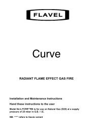
Installer Notification Guidelines<br />
Choose Building<br />
Regulations Notification<br />
Route<br />
Competent Person's<br />
Self Certification Scheme<br />
Building Control<br />
Install and Commission this<br />
appliance to manufacturer's<br />
instructions<br />
Complete the<br />
Benchmark Checklist<br />
Contact your relevant Local<br />
Authority Building Control<br />
(LABC) who will arrange<br />
an inspection or contact<br />
a government approved<br />
inspector<br />
If you notify via the ‘Gas Safe<br />
Register’, the register will issue<br />
the Building Regulations<br />
certificate on members’ behalf<br />
Install and Commission this<br />
appliance to manufacturer's<br />
instructions<br />
Scheme Members only<br />
Call ‘Gas Safe Register’ on:<br />
0800 408 5577<br />
or log onto:<br />
www.gassaferegister.co.uk<br />
within 10 days<br />
Complete the<br />
Benchmark Checklist<br />
You must ensure that the<br />
certificate number issued by<br />
the ‘Gas Safe Register’ is written<br />
onto the Benchmark Checklist<br />
‘Gas Safe Register’ will issue a<br />
Building Regulations Compliance<br />
Certificate to the property owner<br />
and inform the relevant LABC<br />
LABC will record the data<br />
and will issue a<br />
certificate of compliance<br />
© Baxi Heating UK Ltd 2011<br />
3
Legislation<br />
IMPORTANT - Installation, Commissioning, Service & Repair<br />
This appliance must be installed in accordance with the manufacturer’s instructions and<br />
the regulations in force. Read the instructions fully before installing or using the<br />
appliance.<br />
In GB, this must be carried out by a competent person as stated in the Gas Safety<br />
(Installation & Use) Regulations.<br />
Definition of competence: A person who works for a Gas Safe registered company<br />
and holding current certificates in the relevant ACS modules, is deemed competent.<br />
In IE, this must be carried out by a competent person as stated in I.S. 813 “Domestic<br />
Gas Installations”.<br />
The addition of anything that may interfere with the normal operation of the appliance<br />
without express written permission from the manufacturer or his agent could invalidate<br />
the appliance warranty. In GB this could also infringe the Gas Safety (Installation and<br />
Use) Regulations.<br />
Warning - Check the information on the data plate is compatible with local supply<br />
conditions.<br />
All Gas Safe registered engineers carry an ID card with their licence number and a<br />
photograph. You can check your engineer is registered by telephoning<br />
0800 408 5500 or online at www.gasgaferegister.co.uk<br />
This company declares that no substances harmful to<br />
health are contained in the appliance or used during<br />
appliance manufacture.<br />
The appliance is suitable only for installation in GB and IE and<br />
should be installed in accordance with the rules in force, and<br />
only used in a suitably ventilated location.<br />
In GB, the installation must be carried out by a Gas Safe<br />
Registered Installer. It must be carried out in accordance with<br />
the relevant requirements of the:<br />
• Gas Safety (Installation & Use) Regulations.<br />
• The appropriate Building Regulations either The Building<br />
Regulations, The Building Regulations (Scotland), Building<br />
Regulations (Northern Ireland).<br />
• The Water Fittings Regulations or Water Byelaws in<br />
Scotland.<br />
• The Current I.E.E. Wiring Regulations.<br />
Where no specific instructions are given, reference should be<br />
made to the relevant British Standard Code of Practice.<br />
In IE, the installation must be carried out by a competent<br />
Person and installed in accordance with the current edition of<br />
I.S. 813 ‘Domestic Gas Installations’, the current Building<br />
Regulations and reference should be made to the current ETCI<br />
rules for electrical installation.<br />
All systems must be thoroughly flushed and treated with<br />
inhibitor (see section 6.2).<br />
The boiler meets the requirements of Statutory Instrument “ The Boiler (Efficiency)<br />
Regulations 1993 N o 3083” and is deemed to meet the requirements of Directive<br />
92/42/EEC on the energy efficiency requirements for new hot water boilers fired with<br />
liquid or gaseous fuels:-<br />
Type test for purpose of Regulation 5 certified by:<br />
Notified Body 0085.<br />
Product/Production certified by:<br />
Notified Bodies 0085 & 0086.<br />
For GB/IE only.<br />
Codes of Practice - refer to the most recent version<br />
In GB the following Codes of Practice apply:<br />
Standard<br />
Scope<br />
BS 6891<br />
Gas Installation.<br />
BS 5546<br />
Installation of hot water supplies for domestic<br />
purposes.<br />
BS 6798<br />
Installation of gas fired hot water boilers.<br />
BS 5440 Part 1 Flues.<br />
BS 5440 Part 2 Ventilation.<br />
BS 7074<br />
Expansion vessels and ancillary equipment for<br />
sealed water systems.<br />
BS 7593<br />
Treatment of water in domestic hot water<br />
central heating systems.<br />
BS EN 12828 Heating systems in buildings - Design for<br />
water-based heating systems<br />
BS EN 12831 Heating systems in buildings - Method for<br />
calculation of the design heat load<br />
BS EN 14336 Heating systems in buildings - Installation and<br />
commissioning of water-based heating systems<br />
In IE the following Codes of Practice apply:<br />
Standard<br />
Scope<br />
I.S. 813<br />
Domestic Gas Installations.<br />
The following standards give valuable additional information;<br />
BS 5546<br />
Installation of hot water supplies for domestic<br />
purposes.<br />
BS 7074<br />
BS 7593<br />
BS EN 12828<br />
BS EN 12831<br />
BS EN 14336<br />
Expansion vessels and ancillary equipment for<br />
sealed water systems.<br />
Treatment of water in domestic hot water<br />
central heating systems.<br />
Heating systems in buildings - Design for<br />
water-based heating systems<br />
Heating systems in buildings - Method for<br />
calculation of the design heat load<br />
Heating systems in buildings - Installation and<br />
commissioning of water-based heating systems<br />
4<br />
© Baxi Heating UK Ltd 2011
Safe Manual Handling<br />
General<br />
The following advice should be adhered to, from when first handling the boiler to the final stages of installation, and also during maintenance.<br />
Most injuries as a result of inappropriate handling and lifting are to the back, but all other parts of the body are vulnerable, particularly shoulders, arms and hands.<br />
Health & Safety is the responsibility of EVERYONE.<br />
There is no ‘safe’ limit for one man - each person has different capabilities. The boiler should be handled and lifted by TWO PEOPLE.<br />
Do not handle or lift unless you feel physically able.<br />
Wear appropriate Personal Protection Equipment e.g. protective gloves, safety footwear etc.<br />
Preparation<br />
Co-ordinate movements - know where, and when, you are both going.<br />
Minimise the number of times needed to move the boiler - plan ahead.<br />
Always ensure when handling or lifting the route is clear and unobstructed. If possible avoid steps, wet or slippery surfaces, unlit areas etc. and take special care<br />
on ladders/into lofts.<br />
Technique<br />
When handling or lifting always use safe techniques - keep your back straight, bend your knees. Don’t twist - move your feet, avoid bending forwards and<br />
sideways and keep the load as close to your body as possible.<br />
Where possible transport the boiler using a sack truck or other suitable trolley.<br />
Always grip the boiler firmly, and before lifting feel where the weight is concentrated to establish the centre of gravity, repositioning yourself as necessary. See the<br />
‘Installation’ section of these instructions for recommended lift points.<br />
Remember<br />
The circumstances of each installation are different. Always asses the risks associated with handling and lifting according to the individual conditions.<br />
If at any time when installing the boiler you feel that you may have injured yourself STOP !!<br />
DO NOT ‘work through’ the pain - you may cause further injury.<br />
IF IN ANY DOUBT DO NOT HANDLE OR LIFT THE BOILER - OBTAIN ADVICE OR ASSISTANCE BEFORE PROCEEDING !!<br />
© Baxi Heating UK Ltd 2011<br />
5
CONTENTS<br />
Section<br />
Page<br />
1.0 Introduction 7<br />
2.0 General Layout 8<br />
3.0 Appliance Operation 9<br />
4.0 Technical Data 10<br />
5.0 Dimensions and Fixings 11<br />
6.0 <strong>System</strong> Details 12<br />
7.0 Site Requirements 14<br />
8.0 Flue 18<br />
9.0 Installation 20<br />
10.0 Commissioning 25<br />
11.0 Completion & <strong>System</strong> Draining 27<br />
12.0 Servicing 28<br />
13.0 Changing Components 30<br />
14.0 Combustion & Calibration 38<br />
15.0 Electrical 39<br />
16.0 Short Parts List 40<br />
17.0 Fault Finding 41<br />
18.0 32 kW Model Supplement 46<br />
19.0 Page for Notes 49<br />
Benchmark Checklist 50<br />
6 © Baxi Heating UK Ltd 2011
The 12 to 28 kW models in the Baxi <strong>Megaflo</strong> 2<br />
<strong>System</strong> <strong>Compact</strong> <strong>GA</strong> <strong>Range</strong> are of the same<br />
dimensions and layout. The 32 kW model differs<br />
in several respects - these are detailed in<br />
Section 18.0 ‘32 kW Model Supplement’<br />
1.0 Introduction<br />
1.1 Description<br />
1. The Baxi <strong>Megaflo</strong> 2 <strong>System</strong> <strong>Compact</strong> <strong>GA</strong> <strong>Range</strong> are fully<br />
automatic gas fired wall mounted condensing system boilers.<br />
They are room sealed and fan assisted.<br />
2. The boiler is set to give a maximum output of :-<br />
Information Label<br />
12 models - 12 kW<br />
12.7 kW (Condensing)<br />
15 models - 15 kW<br />
15.9 kW (Condensing)<br />
18 models - 18 kW<br />
19 kW (Condensing)<br />
24 models - 24 kW<br />
25.4 kW (Condensing)<br />
28 models - 28 kW<br />
29.6 kW (Condensing)<br />
32 models - 32 kW<br />
33.8 kW (Condensing)<br />
3. The boiler is factory set for use on Natural Gas (G20). It can<br />
be converted to operate on Propane (G31).<br />
Fig. 1<br />
Control Flap<br />
4. The boiler incorporates a circulating pump and expansion<br />
vessel. It is suitable for use only on fully pumped sealed<br />
systems.<br />
5. The boiler data badge gives details of the model, serial<br />
number and Gas Council number and is situated on the inner<br />
door panel. It is visible when the case front panel is removed<br />
(Fig. 2).<br />
6. The boiler model name and serial number are also shown<br />
on the information label on the underside of the facia (Fig. 1).<br />
This is for user reference.<br />
7. The boiler is intended to be installed in residential /<br />
commercial / light industrial E.M.C. environments on a<br />
governed meter supply only.<br />
8. The boiler must be installed with one of the purpose<br />
designed flues such as one of the standard horizontal<br />
telescopic flue kits detailed in the Flue Installation Guide .<br />
9. All systems must be thoroughly flushed and treated with<br />
inhibitor (see section 6.2).<br />
Gas Type Label<br />
Fig. 2<br />
Data Badge<br />
1.2 Optional Extras<br />
Various timers, external controls, etc. are available as optional<br />
extras. Full details are contained in the relevant sales<br />
literature.<br />
1.3 Contents of Pack<br />
NOTE: These Installation & Servicing Instructions MUST be<br />
read in conjunction with the Flue Installation Guide<br />
supplied in the Literature Pack.<br />
The pack contains:-<br />
• Boiler<br />
• Wall Plate (including taps)<br />
• Template<br />
• Literature Pack<br />
© Baxi Heating UK Ltd 2011<br />
7
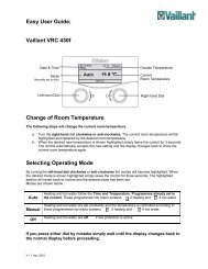
2.0 General Layout<br />
10<br />
9<br />
8<br />
7<br />
6<br />
3<br />
2<br />
1<br />
2.1 Layout 12 - 28 Models<br />
1. Expansion Vessel<br />
2. Boiler Adaptor<br />
3. Primary Heat Exchanger<br />
4. Pump with Automatic Air Vent<br />
5. Central Heating <strong>System</strong> Pressure Gauge<br />
6. Fan Assembly<br />
7. Flame Sensing Electrode<br />
8. Air/Gas Collector<br />
9. Spark Ignition Electrode<br />
10. Combustion Box Cover & Burner<br />
11. Condensate Trap<br />
12. Safety Pressure Relief Valve<br />
13 Boiler Control<br />
14. Gas Valve<br />
15. Boiler Drain Tap<br />
16. Control Box Display<br />
11<br />
12<br />
13<br />
16<br />
14<br />
4<br />
5<br />
15<br />
8<br />
© Baxi Heating UK Ltd 2011
13<br />
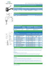
3.0 Appliance Operation<br />
12<br />
14<br />
15<br />
3.1 Operating Mode<br />
1. With a demand for heating, the pump circulates water<br />
through the primary circuit.<br />
16<br />
2. Once main burner ignites the fan speed controls the gas<br />
rate to maintain the heating temperature measured by the<br />
temperature sensor.<br />
18<br />
17<br />
3. When the flow temperature exceeds the setting<br />
temperature, a 3 minute delay occurs before the burner<br />
relights automatically (anti-cycling). The pump continues to<br />
run during this period.<br />
19<br />
4. When the demand is satisfied the burner is extinguished<br />
and the pump continues to run for a period of 3 minutes<br />
(Pump Overrun).<br />
20<br />
11<br />
10<br />
21<br />
22<br />
3.2 Boiler Frost Protection Mode<br />
1. The frost protection mode is integral to the appliance and<br />
functions as long as there is power to the boiler, as indicated<br />
by the standby signal .<br />
9<br />
2. When the boiler temperature falls below 5°C the boiler<br />
will fire until a temperature of 30°C is reached.<br />
1<br />
3. Further protection can be incorporated by using a system<br />
frost thermostat.<br />
3.3 Pump Protection<br />
8<br />
7<br />
5<br />
3<br />
2<br />
1. If the boiler has been inactive for a period of 24 hours the<br />
pump will automatically operate for 1 minute to prevent<br />
sticking.<br />
A<br />
6<br />
4<br />
B C D<br />
Fig. 3<br />
Key<br />
1. Pump with Automatic Air Vent<br />
2. CH <strong>System</strong> Pressure Gauge<br />
3. Central Heating Filter<br />
4. Non-return valve<br />
5. Hydraulic Pressure Sensor<br />
6. Boiler Drain Tap<br />
7. Pressure Relief Valve<br />
8. Condensate Trap<br />
9. Gas Valve<br />
10. Safety Thermostat 105°C<br />
11. Heating Flow Sensor<br />
12. Flue Sensor<br />
13. Boiler Adaptor<br />
14. Primary Heat Exchanger<br />
15. Spark Ignition Electrode<br />
16. Burner<br />
17. Flame Sensing Electrode<br />
18. Air/Gas Collector<br />
19. Heating Return Sensor<br />
20. Fan<br />
21. Air-Gas Venturi<br />
22. Expansion Vessel<br />
Connections:-<br />
A – Condensate Drain<br />
B – Heating Flow<br />
C – Gas Inlet<br />
D – Heating Return<br />
© Baxi Heating UK Ltd 2011<br />
9
4.0 Technical Data<br />
4.1 (See Section 18.0 for 32 kW model)<br />
Appliance Type C 13 C 33 C 43 C 53<br />
Appliance Category<br />
Injector<br />
12 model mm 3<br />
15 model mm 3.3<br />
18 model mm 3.6<br />
24 model mm 4.6<br />
28 model mm 4.9<br />
CAT I 2H 3P<br />
Heat Input CH (Net) Max Min<br />
12 model kW 12 2.1<br />
15 model kW 15 2.2<br />
18 model kW 18 2.6<br />
24 model kW 24 3.5<br />
28 model kW 28 4.1<br />
Heat Output CH (Non-Condensing)<br />
Max Min<br />
12 model kW 12 2<br />
15 model kW 15 2.1<br />
18 model kW 18 2.5<br />
24 model kW 24 3.4<br />
28 model kW 28 4<br />
Heat Output CH (Condensing)<br />
Max Min<br />
12 model kW 12.7 2.2<br />
15 model kW 15.9 2.3<br />
18 model kW 19 2.8<br />
24 model kW 25.4 3.7<br />
28 model kW 29.6 4.3<br />
NATURAL <strong>GA</strong>S ONLY !<br />
Max Gas Rate (Natural Gas - G20)<br />
(After 10 mins)<br />
12 model m 3 /h 1.27<br />
15 model m 3 /h 1.59<br />
18 model m 3 /h 1.90<br />
24 model m 3 /h 2.54<br />
28 model m 3 /h 2.96<br />
Inlet Pressure (Natural Gas - G20)<br />
mbar 20<br />
PROPANE ONLY !<br />
Max Gas Rate (Propane - G31)<br />
(After 10 mins)<br />
12 model kg/h 0.93<br />
15 model kg/h 1.17<br />
18 model kg/h 1.4<br />
24 model kg/h 1.86<br />
28 model kg/h 2.18<br />
Inlet Pressure (Propane - G31)<br />
mbar 37<br />
NOTE: All data in this section are nominal values<br />
and subject to normal production tolerances.<br />
Electrical Supply<br />
230V~ 50H z<br />
(Appliance must be connected to an<br />
earthed supply)<br />
Power Consumption<br />
12 model W 110<br />
15 model W 108<br />
18 model W 125<br />
24 model W 104<br />
28 model W 135<br />
Electrical Protection<br />
IPX5D<br />
External Fuse Rating<br />
Internal Fuse Rating<br />
Flue Terminal Diameter 100mm<br />
Dimensions Projection 125mm<br />
Connections<br />
copper tails<br />
Gas Inlet - 22mm<br />
Heating Flow - 22mm<br />
Heating Return - 22mm<br />
Pressure Relief Discharge - 15mm<br />
Clearances<br />
Above Casing 175 mm Min<br />
Below Casing 150mm Min*<br />
Front<br />
450mm Min (For Servicing)<br />
Front<br />
5mm Min (In Operation)<br />
L.H. Side<br />
5mm Min<br />
R.H. Side 5mm Min<br />
*This is MINIMUM recommended dimension. Greater<br />
clearance will aid installation and maintenance.<br />
Outercase Dimensions<br />
Casing Height<br />
Overall Height Inc Flue Elbow<br />
Casing Width<br />
Casing Depth<br />
3A<br />
F2L<br />
Condensate Drain<br />
To accept 21.5mm ( 3 /4 in) plastic waste pipe<br />
- 700mm<br />
- 860mm<br />
- 390mm<br />
- 300*mm<br />
*This can be reduced to 290mm by removing the<br />
boiler control access flap<br />
SEDBUK Declaration<br />
SAP 2005 Seasonal Efficiency for N. G.<br />
models is 91.1%<br />
SAP 2005 Seasonal Efficiency for L.P.G.<br />
models is 93.2%<br />
SAP 2009 Annual Efficiency for N. G.<br />
models is 89%<br />
SAP 2009 Annual Efficiency for L.P.G.<br />
models is 91%<br />
This value is used in the UK Government’s Standard<br />
Assessment Procedure (SAP) for energy rating of<br />
dwellings. The test data from which it has been calculated<br />
has been certified by 0087.<br />
Metre (wg)<br />
Weights<br />
Packaged Boiler Carton<br />
Installation Lift Weight<br />
Packaged Boiler Carton<br />
Installation Lift Weight<br />
NO x Class 5<br />
Central Heating Primary Circuit<br />
Pressures<br />
bar<br />
Safety Discharge 3<br />
Max Operating 2.5<br />
Min Operating 0.5<br />
Recommended Operating <strong>Range</strong> 1-2<br />
Pump<br />
Available Head<br />
6<br />
5.5<br />
5<br />
4.5<br />
4<br />
3.5<br />
3<br />
2.5<br />
2<br />
1.5<br />
1<br />
0.5<br />
0<br />
0<br />
See graph below<br />
Expansion Vessel - (For Central Heating only.<br />
Integral with appliance)<br />
bar<br />
Min Pre-charge Pressure 0.5<br />
(12, 15, 18, 24 & 28)<br />
litre<br />
Max Capacity of<br />
CH <strong>System</strong> 100<br />
Primary Water Content<br />
of Boiler (unpressurised) 2.5<br />
Temperatures<br />
C.H. Flow Temp (adjustable)<br />
25°C to 80°C max (± 5°C)<br />
Pump - Available Head<br />
200 400 600 800 1000 1200<br />
Flow Rate (l/h)<br />
(12/15/18/24)<br />
36.5kg<br />
32.5kg<br />
(28 model)<br />
38.5kg<br />
34.5kg<br />
10<br />
© Baxi Heating UK Ltd 2011
5.0 Dimensions and Fixings<br />
Dimensions<br />
At least 1.5°<br />
G<br />
E<br />
A<br />
700mm<br />
A<br />
B 300*mm<br />
*This can be reduced to 290mm by<br />
removing the boiler control access flap<br />
C 390mm<br />
D 116mm Ø Min.<br />
E<br />
160mm<br />
(207mm for 80/125mm<br />
flue systems)<br />
B<br />
360° Orientation<br />
F<br />
130mm<br />
G 106mm<br />
D<br />
C<br />
H<br />
J<br />
H 228mm<br />
J<br />
162mm<br />
Flue Ø 100mm<br />
F<br />
Tap Rail<br />
Boiler<br />
Side<br />
Boiler<br />
Side<br />
Condensate<br />
Drain<br />
40 mm<br />
Pressure<br />
Relief<br />
Valve<br />
(15mm)<br />
25<br />
mm 130 mm<br />
130 mm 65 mm<br />
Heating<br />
Flow<br />
(22mm)<br />
162.5 mm<br />
Gas<br />
Inlet<br />
(22mm)<br />
Heating<br />
Return<br />
(22mm)<br />
© Baxi Heating UK Ltd 2011<br />
11
6.0 <strong>System</strong> Details<br />
6.1 Information<br />
1. The Baxi <strong>Megaflo</strong> 2 <strong>System</strong> <strong>Compact</strong> Condensing Boiler is a<br />
‘Water Byelaws Scheme - Approved Product’.<br />
To comply with the Water Byelaws your attention is drawn to<br />
the following installation requirements and notes (IRN).<br />
a) IRN 001 - See text of entry for installation<br />
requirements and notes.<br />
b) IRN 302 - Byelaw 14.<br />
2. Reference to the WRc publications, ‘Water fittings and<br />
materials directory’ and ‘Water supply byelaws guide’ give full<br />
details of byelaws and the IRNs.<br />
6.2 Treatment of Water Circulating <strong>System</strong>s<br />
1. All recirculatory water systems will be subject to corrosion<br />
unless they are flushed and an appropriate water treatment is<br />
applied. To prevent this, follow the guidelines given in BS<br />
7593 “Treatment of Water in Domestic Hot Water Central<br />
Heating <strong>System</strong>s” and the treatment manufacturers<br />
instructions.<br />
2. Treatment must involve the use of a proprietary cleanser,<br />
such as Sentinel X300 or X400, or Fernox F3 and an inhibitor<br />
such as Sentinel X100 or Fernox MB-1.<br />
3. Full instructions are supplied with the products, for further<br />
information contact Sentinel (0800 389 4670) or Fernox<br />
(0870 870 0362).<br />
Failure to flush and add inhibitor to the system will<br />
invalidate the appliance warranty.<br />
4. It is important to check the inhibitor concentration after<br />
installation, system modification and at every service in<br />
accordance with the inhibitor manufacturer’s instructions.<br />
(Test kits are available from inhibitor stockists.)<br />
5. For information or advice regarding any of the above<br />
contact Technical Enquiries 0844 871 1555.<br />
6.3 Bypass<br />
1. The boiler is fitted with an automatic integral bypass. Some<br />
systems may require an additional external bypass.<br />
6.4 <strong>System</strong> Control<br />
1. Further external controls (e.g. room thermostat sensors)<br />
MUST be fitted to optimise the economical operation of the<br />
boiler in accordance with Part L of the Building Regulations<br />
(2010). A range of optional controls are available. Full details<br />
are contained in the relevant Sales Literature.<br />
12<br />
© Baxi Heating UK Ltd 2011
6.0 <strong>System</strong> Details<br />
6.5 <strong>System</strong> Filling and Pressurising<br />
Stop<br />
Valve<br />
Double<br />
Check<br />
Valve<br />
Stop<br />
Valve<br />
1. A filling point connection on the central heating return<br />
pipework must be provided to facilitate initial filling and<br />
pressurising and also any subsequent water loss<br />
replacement/refilling.<br />
Fig. 4<br />
DHW<br />
Mains<br />
Inlet<br />
Temporary<br />
Loop<br />
CH<br />
Return<br />
2. The filling method adopted must be in accordance with all<br />
relevant water supply regulations and use approved<br />
equipment.<br />
3. Your attention is drawn to:<br />
for GB: Guidance G24.2 and recommendation R24.2 of the<br />
Water Regulations Guide.<br />
for IE: the current edition of I.S. 813 “Domestic Gas<br />
Installations”.<br />
4. The sealed primary circuits may be filled or replenished by<br />
means of a temporary connection between the circuit and a<br />
supply pipe, provided a ‘Listed’ double check valve or some<br />
other no less effective backflow prevention device is<br />
permanently connected at the inlet to the circuit and the<br />
temporary connection is removed after use.<br />
6.6 Expansion Vessel (Central Heating only)<br />
Fig. 5<br />
1. The appliance expansion vessel is pre-charged to 0.5 bar.<br />
Therefore, the minimum cold fill pressure is 0.5 bar. The<br />
vessel is suitable for correct operation for system capacities up<br />
to 100 litres (32 kW model - 155 litres). For greater system<br />
capacities an additional expansion vessel must be fitted. For<br />
GB refer to BS 7074 Pt 1. For IE, the current edition of I.S.<br />
813 “Domestic Gas Installations”.<br />
6.7 Safety Pressure Relief Valve (Fig. 6)<br />
1. The pressure relief valve is set at 3 bar, therefore all<br />
pipework, fittings, etc. should be suitable for pressures in<br />
excess of 3 bar and temperature in excess of 100°C.<br />
2. The pressure relief discharge pipe should be not less than<br />
15mm dia, run continuously downward, and discharge outside<br />
the building, preferably over a drain. It should be routed in<br />
such a manner that no hazard occurs to occupants or causes<br />
damage to wiring or electrical components. The end of the<br />
pipe should terminate facing down and towards the wall.<br />
3. The discharge must not be above a window, entrance or<br />
other public access. Consideration must be given to the<br />
possibility that boiling water/steam could discharge from the<br />
pipe.<br />
Control Box removed<br />
for clarity<br />
4. A remote relief valve kit is available to enable the boiler to<br />
be installed in cellars or similar locations below outside<br />
ground level (kit no. 5121379).<br />
Pressure Relief Valve<br />
Fig. 6<br />
Discharge Pipe<br />
5. A boiler discharge pump is available, part no. 720648301.<br />
This pump will dispose of both condensate & high<br />
temperature water from the relief valve. It has a maximum<br />
head of 5 metres.<br />
© Baxi Heating UK Ltd 2011<br />
13
5mm Min<br />
390mm<br />
5mm Min<br />
7.0 Site Requirements<br />
7.1 Location<br />
175mm Min<br />
(300mm Min if<br />
using 80/125mm<br />
flueing system)<br />
1. The boiler may be fitted to any suitable wall with the flue<br />
passing through an outside wall or roof and discharging to<br />
atmosphere in a position permitting satisfactory removal of<br />
combustion products and providing an adequate air supply.<br />
The boiler should be fitted within the building unless<br />
otherwise protected by a suitable enclosure i.e. garage or<br />
outhouse. (The boiler may be fitted inside a cupboard-see<br />
Section 7.3).<br />
2. If the boiler is sited in an unheated enclosure then it is<br />
recommended to leave the ON/OFF Selector Switch in the<br />
domestic hot water and central heating position to give frost<br />
protection.<br />
700mm<br />
3. If the boiler is fitted in a room containing a bath or shower<br />
reference must be made to the relevant requirements.<br />
In GB this is the current I.E.E. Wiring Regulations and Building<br />
Regulations.<br />
In IE reference should be made to the current edition of I.S.<br />
813 “Domestic Gas Installations” and the current ETCI rules.<br />
4. If the boiler is to be fitted into a building of timber frame<br />
construction then reference must be made to the current<br />
edition of Institute of Gas Engineers Publication IGE/UP/7<br />
(Gas Installations in Timber Framed Housing).<br />
Fig. 8<br />
150mm* Min<br />
7.2 Clearances (Figs. 8 & 9)<br />
1. A flat vertical area is required for the installation of the<br />
boiler.<br />
At least 1.5°<br />
2. These dimensions include the necessary clearances around<br />
the boiler for case removal, spanner access and air<br />
movement. Additional clearances may be required for the<br />
passage of pipes around local obstructions such as joists<br />
running parallel to the front face of the boiler.<br />
*This is MINIMUM recommended dimension. Greater<br />
clearance will aid installation and maintenance.<br />
7.3 Ventilation of Compartments<br />
450mm Min<br />
For Servicing<br />
Purposes<br />
1. Where the appliance is installed in a cupboard or<br />
compartment, no air vents are required.<br />
2. BS 5440: Part 2 refers to room sealed appliances installed<br />
in compartments. The appliance will run sufficiently cool<br />
without ventilation.<br />
5mm Min<br />
In Operation<br />
300mm<br />
(290mm with flap removed)<br />
Fig. 9<br />
14<br />
© Baxi Heating UK Ltd 2011
7.0 Site Requirement<br />
7.4 Gas Supply<br />
1. The gas installation should be in accordance with the<br />
relevant standards. In GB this is BS 6891. In IE this is the<br />
current edition of I.S. 813 “Domestic Gas Installations”.<br />
2. The connection to the appliance is a 22mm copper tail<br />
located at the rear of the gas service cock (Fig. 10).<br />
3. Ensure that the pipework from the meter to the<br />
appliance is of adequate size, and the demands of any<br />
other gas appliances in the property are taken into<br />
consideration. Do not use pipes of a smaller diameter than<br />
the boiler gas connection (22mm).<br />
Fig. 10<br />
Gas Service Cock<br />
7.5 Electrical Supply<br />
1. External wiring must be correctly earthed, polarised and<br />
in accordance with relevant regulations/rules. In GB this is<br />
the current I.E.E. Wiring Regulations. In IE reference should<br />
be made to the current edition of ETCI rules.<br />
Zone 1<br />
Zone 0<br />
Zone 2<br />
Window<br />
Recess<br />
Zone 2<br />
0.6 m<br />
2. The mains supply is 230V ~ 50H z fused at 3A.<br />
NOTE: The method of connection to the electricity<br />
supply must facilitate complete electrical isolation of the<br />
appliance.<br />
Connection may be via a fused double-pole isolator<br />
with a contact separation of at least 3mm in all poles<br />
and servicing the boiler and system controls only.<br />
Window<br />
Recess<br />
Zone 2<br />
7.6 Bath & Shower Rooms<br />
Fig. A<br />
In GB Only<br />
Window Recess<br />
Zone 2<br />
Ceiling<br />
Outside Zones<br />
1. If the boiler is fitted in a room containing a bath or<br />
shower it can be fitted in zone 2, (Figs. A & B shows zone<br />
dimensions for a bathtub. For other examples refer to the<br />
Current I.E.E. Wiring Regulations) reference must be made<br />
to the relevant requirements.<br />
In GB this is the current I.E.E. Wiring Regulations and<br />
Building Regulations.<br />
In IE reference should be made to the current edition of I.S.<br />
813 “Domestic Gas Installations” and the current ETCI<br />
rules.<br />
Zone 1<br />
Zone 2<br />
2.25 m<br />
Zone 0<br />
0.6 m<br />
Fig. B<br />
In GB Only<br />
© Baxi Heating UK Ltd 2011<br />
15
7.0 Site Requirements<br />
Sink<br />
Boiler<br />
50mm per metre of pipe run<br />
2.5° Minimum fall<br />
450mm min<br />
Boiler<br />
Termination to an internal soil and<br />
vent pipe<br />
50mm per metre of pipe run<br />
2.5° Minimum fall<br />
External termination via internal discharge<br />
branch<br />
e.g sink waste - downstream<br />
Pipe must terminate<br />
above water level but<br />
below surrounding<br />
surface<br />
Termination to a drain or gully<br />
7.7 Condensate Drain<br />
FAILURE TO INSTALL THE CONDENSATE DISCHARGE<br />
PIPEWORK CORRECTLY WILL AFFECT THE RELIABLE<br />
OPERATION OF THE BOILER.<br />
CAREFUL CONSIDERATION MUST BE GIVEN TO THE<br />
POSSIBILITY OF THE PIPEWORK BEING SUBJECT TO<br />
FREEZING CONDITIONS AND APPROPRIATE MEASURES<br />
TAKEN TO PREVENT BLOCKAGE.<br />
The condensate discharge pipe MUST NOT RISE at any point<br />
along its length. There MUST be a fall of AT LEAST 2.5°<br />
(50mm per metre) along the entire run.<br />
1. The condensate outlet will accept 21.5mm ( 3 /4in) plastic<br />
overflow pipe which should generally discharge internally into<br />
the household drainage system. If this is not possible, discharge<br />
into an outside drain is acceptable.<br />
2. Ensure the discharge of condensate complies with any<br />
national or local regulations in force.<br />
BS 6798 & Part H1 of the Building Regulations give further<br />
guidance.<br />
3. The discharge pipe should be run in a proprietary drain pipe<br />
material e.g. PVC, PVC-U, ABS, PVC-C or PP.<br />
4. Metal pipework is NOT suitable for use in condensate<br />
discharge systems.<br />
5. The pipe should be a minimum of 21.5mm diameter and<br />
must be supported using suitably spaced clips to prevent<br />
sagging.<br />
6. It is advisable that the full length of condensate pipe is run<br />
internally and preferably be less than 3 metres.<br />
Boiler<br />
50mm per metre of pipe run<br />
2.5° Minimum fall<br />
Pipe must terminate above<br />
water level but below<br />
surrounding surface<br />
7. Internal runs greater than 3 metres or runs in cold areas<br />
should use 32mm waste pipe.<br />
8. External runs MUST be a MINIMUM of 32mm and fully<br />
insulated.<br />
9. If the boiler is fitted in an unheated location the entire<br />
condensate discharge pipe should be treated as an external<br />
run.<br />
Boiler<br />
Termination to a purpose made soakaway<br />
500mm min<br />
10. In all cases discharge pipe must be installed to aid disposal<br />
of the condensate. To reduce the risk of condensate being<br />
trapped, as few bends and fittings as possible should be used.<br />
11. When discharging condensate into a soil stack or waste<br />
pipe the effects of existing plumbing must be considered. If soil<br />
pipes or waste pipes are subjected to internal pressure<br />
fluctuations when WC's are flushed or sinks emptied then<br />
back-pressure may force water out of the boiler trap and<br />
cause appliance lockout.<br />
50mm per metre of pipe run<br />
2.5° Minimum fall<br />
Holes in the soak-away must<br />
face away from the building<br />
Examples are shown of the following methods of termination:-<br />
i) to an internal soil & vent pipe<br />
ii) via an internal discharge branch (e.g. sink waste)<br />
iii) to a drain or gully<br />
iv) to a purpose made soakaway<br />
16<br />
© Baxi Heating UK Ltd 2011
Terminal Position with Minimum Distance (Fig. 12)<br />
Terminal<br />
Assembly<br />
300 min<br />
(mm)<br />
A 1 Directly below an opening, air brick, opening<br />
windows, etc. 300<br />
B 1 Above an opening, air brick, opening window etc. 300<br />
C 1 Horizontally to an opening, air brick, opening window etc. 300<br />
D 2 Below gutters, soil pipes or drain pipes. 25<br />
E 2 Below eaves. 25<br />
F 2 Below balconies or car port roof. 25<br />
G 2 From a vertical drain pipe or soil pipe. 25<br />
H 2 From an internal or external corner. 25<br />
I Above ground, roof or balcony level. 300<br />
J From a surface or boundary line facing a terminal. 600<br />
K From a terminal facing a terminal (Horizontal flue). 1200<br />
From a terminal facing a terminal (Vertical flue). 600<br />
L From an opening in carport (e.g. door, window)<br />
into the dwelling. 1200<br />
M Vertically from a terminal on the same wall. 1500<br />
N Horizontally from a terminal on the same wall. 300<br />
R From adjacent wall to flue (vertical only). 300<br />
S From an adjacent opening window (vertical only). 1000<br />
T Adjacent to windows or openings on pitched and flat roofs 600<br />
U Below windows or openings on pitched roofs 2000<br />
1 In addition, the terminal should be no nearer than 150 mm to an opening in the<br />
building fabric formed for the purpose of accommodating a built-in element such as<br />
a window frame.<br />
2 Only ONE 25mm clearance is allowed per installation. If one of the dimensions<br />
D, E, F, G or H is 25mm then the remainder MUST be as B.S.5440-1.<br />
NOTE: The distance from a fanned draught appliance terminal<br />
installed parallel to a boundary may not be less than 300mm in<br />
accordance with the diagram below<br />
7.0 Site Requirements<br />
7.8 Flue<br />
NOTE: Due to the nature of the boiler a plume of water<br />
vapour will be discharged from the flue. This should be<br />
taken into account when siting the flue terminal.<br />
1. The following guidelines indicate the general requirements<br />
for siting balanced flue terminals. For GB recommendations<br />
are given in BS 5440 Pt 1. For IE recommendations are given<br />
in the current edition of I.S. 813 “Domestic Gas<br />
Installations”.<br />
2. If the terminal discharges onto a pathway or passageway,<br />
check that combustion products will not cause a nuisance<br />
and that the terminal will not obstruct the passageway.<br />
3. If a terminal is less than 2 metres above a balcony, above<br />
ground or above a flat roof to which people have access,<br />
then a suitable terminal guard must be provided.<br />
IMPORTANT:<br />
• Under car ports we recommend the use of the plume<br />
displacement kit.<br />
• The terminal position must ensure the safe and<br />
nuisance - free dispersal of combustion products.<br />
*4. Reduction to the boundary is possible down to 25mm<br />
but flue deflector part no. 5111068 must be used.<br />
Fig. 11<br />
Top View Rear Flue<br />
Plume<br />
Displacement Kit<br />
IMPORTANT: If fitting a Plume<br />
Displacement Flue Kit, the air inlet<br />
must be a minimum of 150mm from<br />
any opening windows or doors (see<br />
Section 9.0).<br />
Property Boundary Line<br />
J,K<br />
T<br />
U<br />
Air Inlet<br />
Opening Window<br />
or Door<br />
150mm<br />
MIN.<br />
Fig. 13<br />
R<br />
M<br />
N<br />
C<br />
D<br />
E<br />
A<br />
I<br />
I<br />
I<br />
S<br />
I<br />
F<br />
L<br />
G<br />
A<br />
I<br />
B<br />
H<br />
A F H<br />
J,K<br />
Likely flue positions requiring<br />
a flue terminal guard<br />
Fig. 12<br />
© Baxi Heating UK Ltd 2011<br />
17
8.0 Flue<br />
(i)<br />
(ii)<br />
8.1 Horizontal Flue <strong>System</strong>s<br />
1. The standard flue is suitable only for horizontal<br />
termination applications.<br />
2. All fittings should be fully engaged. The approximate<br />
engagement is 40mm. Apply the lubricant supplied to the<br />
seal on each fitting to aid assembly.<br />
3. Maximum permissible equivalent flue lengths are:-<br />
(60/100) (80/125)<br />
Horizontal Concentric 10 metres 20 metres<br />
4. Any additional “in line” bends in the flue system must be<br />
taken into consideration.<br />
Their equivalent lengths are:-<br />
Concentric Pipes:<br />
135° bend 0.5 metres<br />
93° bend 1.0 metres<br />
Plume Displacement Kit 60 /100 dia<br />
1M Extensions 45° & 93° elbows<br />
are also available.<br />
Horizontal<br />
Flues<br />
5. The elbow supplied with the standard horizontal<br />
telescopic flue kit is not included in any equivalent length<br />
calculations.<br />
NOTE: Flue length is measured from point (i) to (ii) as<br />
shown.<br />
IMPORTANT<br />
SUPPORT - All flue systems MUST be securely<br />
supported a MINIMUM of once every metre. It is<br />
recommended that every straight piece is supported<br />
irrespective of length. Additional supports are available<br />
as accessories.<br />
VOIDS - Consideration must be given to flue systems<br />
in voids and the provision of adequate access for<br />
subsequent periodic visual inspection.<br />
NOTE: Horizontal flue pipes should always be installed with a fall of at least 1.5°<br />
from the terminal to allow condensate to run back to the boiler.<br />
6. Read this section in conjunction with the Flue Installation<br />
Guide supplied with the boiler.<br />
A<br />
This bend is equivalent to<br />
1 metre<br />
B<br />
C<br />
(ii)<br />
(i)<br />
This bend is equivalent to<br />
1 metre<br />
Total equivalent length =<br />
A+B+C+2 x 90° Bends<br />
18<br />
© Baxi Heating UK Ltd 2011
8.0 Flue<br />
8.2 Flue Lengths<br />
315mm 500mm<br />
Fig. 14<br />
Flue Deflector<br />
The standard horizontal telescopic flue kit allows for lengths<br />
between 315mm and 500mm from elbow to terminal (Fig. 14).<br />
Extensions of 250mm, 500mm & 1m are available.<br />
The maximum permissible equivalent flue length is:<br />
10 metres (60/100 system - vertical & horizontal)<br />
20 metres (80/125 system - vertical & horizontal)<br />
15 metres (80/80 twin pipe)<br />
8 metres (60/100 system - vertical connected to<br />
ridge terminal)<br />
8.3 Flue Trim<br />
1. The flexible flue trims supplied can be fitted on the outer and<br />
inner faces of the wall of installation.<br />
Fig. 16<br />
8.4 Terminal Guard (Fig. 15)<br />
1. When codes of practice dictate the use of terminal guards, they<br />
can be obtained from most <strong>Plumb</strong>ers’ and Builders’ Merchants.<br />
2. There must be a clearance of at least 50mm between any part<br />
of the terminal and the guard.<br />
3. When ordering a terminal guard, quote the appliance name<br />
and model number.<br />
Fig. 15<br />
4. The flue terminal guard should be positioned centrally over the<br />
terminal and fixed as illustrated.<br />
8.5 Flue Deflector (Fig. 16)<br />
1. If required, push the flue deflector over the terminal end and<br />
rotate to the optimum angle for deflecting plume. Secure the<br />
deflector to the terminal with screws provided.<br />
8.6 Flue Accessories<br />
1. For full details of Flue Accessories (elbows, extensions, clamps<br />
etc.) refer to the Flue Installation Guide supplied in the literature<br />
pack.<br />
© Baxi Heating UK Ltd 2011<br />
19
9.0 Installation<br />
9.1 Unpacking & Initial Preparation<br />
IMPORTANT<br />
RISK ASSESSMENT - Before commencing the installation<br />
it is recommended that the ‘Five Steps to Risk<br />
Assessment’ document published by the HSE is<br />
consulted, and an assessment performed as described.<br />
<strong>GA</strong>S SUPPLY - The gas supply, gas type and pressure<br />
must be checked for suitability before connection (see<br />
Section 7.4).<br />
NOTE: a small amount of water may drain from the boiler<br />
in the upright position.<br />
Fig. 17<br />
1. Remove staples, open flaps and remove the cardboard<br />
sheet. Remove the polystyrene side pieces and literature. Two<br />
people can then lift out the boiler (Fig. 17).<br />
2. After considering the site requirements<br />
(see Section 7.0) position the fixing template on the wall<br />
ensuring it is level both horizontally and vertically.<br />
116mm Dia Minimum<br />
Aperture For Flue Tube<br />
3. Mark the position of the two most suitable fixing slots for<br />
the wall plate and boiler lower fixing holes.<br />
130mm<br />
175mm<br />
Minimum<br />
Clearance<br />
Vertical Flue<br />
Centre Line<br />
228 mm<br />
Side Flue<br />
Centre Line<br />
4. Mark the position of the centre of the flue hole (rear exit).<br />
For side flue exit, mark as shown (Fig. 18).<br />
Boiler Mounting Bracket<br />
Fixing Slots<br />
5. If required, mark the position of the gas and water pipes.<br />
Remove the template.<br />
For Side Flue Exit<br />
50 mm<br />
6. Cut the hole for the flue (minimum diameter 116mm).<br />
Fig. 18<br />
8mm Dia<br />
Profile of<br />
Outercase<br />
8mm Dia<br />
7. Drill the wall as previously marked to accept the wall plugs<br />
supplied. Secure the wall plate using the fixing screws.<br />
8. Using a spirit level ensure that the plate is level before finally<br />
tightening the screws.<br />
5 mm Minimum<br />
Side Clearance<br />
5 mm Minimum<br />
Side Clearance<br />
9. Connect the gas and water pipes to the valves on the wall<br />
plate using the copper tails supplied. Ensure that the sealing<br />
washers are fitted between the connections.<br />
9.2 Flushing<br />
Condensate<br />
Drain<br />
Pressure<br />
200mm<br />
Relief<br />
Recommended<br />
Valve<br />
150mm<br />
(15mm)<br />
Minimum<br />
Clearance<br />
25<br />
40 mm mm 130 mm 130 mm 65 mm<br />
162.5 mm<br />
Heating<br />
Gas<br />
Heating<br />
Flow<br />
Inlet<br />
Return<br />
(22mm)<br />
(22mm)<br />
(22mm)<br />
1. Connect a tube to the heating flow or return pipe (Fig. 20).<br />
2. Flush thoroughly (see <strong>System</strong> Details, Section 6.2).<br />
Fig. 19<br />
Flushing Tube<br />
Heating Flow<br />
Fig. 20<br />
Heating Return<br />
20<br />
© Baxi Heating UK Ltd 2007
Boiler Mounting<br />
Bracket (shown<br />
exploded for clarity)<br />
9.0 Installation<br />
9.3 Fitting The Boiler<br />
1. Remove the sealing caps from the boiler connections.<br />
Sealing Washers<br />
NOTE: A small amount of water may drain from the<br />
boiler once the caps are removed.<br />
2. Lift the boiler as indicated by the shaded areas. The boiler<br />
should be lifted by TWO PEOPLE. Engage the mounting<br />
bracket at the top rear of the boiler on the wall plate (Fig.<br />
21) (see Safe Manual Handling page 5).<br />
3. Insert the sealing washers between the valves and pipes<br />
on the wall plate and the boiler connections.<br />
Suggested Lifting Points<br />
shown as shaded area<br />
Pressure Relief Valve<br />
Fig. 21<br />
Remove Sealing Caps from<br />
under the Boiler after lifting<br />
into position<br />
Prime Trap by pouring<br />
300ml of water into<br />
flue spigot<br />
4. Tighten all the connections.<br />
9.4 Fitting the Pressure Relief Discharge Pipe<br />
(Fig. 22)<br />
1. Remove the discharge pipe from the kit.<br />
2. Determine the routing of the discharge pipe in the vicinity<br />
of the boiler. Make up as much of the pipework as is<br />
practical, including the discharge pipe supplied.<br />
IMPORTANT: Make all soldered joints before connecting<br />
to the pressure relief valve.<br />
3. The pipework must be at least 15mm diameter and run<br />
continuously downwards to a discharge point outside the<br />
building. See section 6.7 for further details.<br />
4. Utilising one of the sealing washers, connect the discharge<br />
pipe to the adaptor and tighten the nut hand tight, plus 1/4<br />
turn to seal.<br />
5. Complete the discharge pipework and route it to the<br />
outside discharge point.<br />
9.5 Condensate Drain (see section 7.7) (Fig. 23)<br />
Fig. 22<br />
Discharge Pipe<br />
Control Box removed<br />
for clarity<br />
1. Using the short piece of rubber hose supplied, connect the<br />
condensate drain pipework to the boiler condensate trap<br />
outlet pipe.<br />
Ensure the discharge of condensate complies with any<br />
national or local regulations in force (see British Gas<br />
“Guidance Notes for the Installation of Domestic Gas<br />
Condensing Boilers” & HHIC recommendations).<br />
2. The hose will accept 21.5mm ( 3 /4in) plastic overflow pipe<br />
which should generally discharge internally into the<br />
household drainage system. If this is not possible, discharge<br />
into an outside drain is acceptable.<br />
Condensate Trap<br />
Outlet Pipe<br />
Fig. 23<br />
3. The boiler condensate trap should be primed by pouring<br />
approximately 300ml of water into the flue spigot. Do not<br />
allow any water to fall into the air inlet.<br />
© Baxi Heating UK Ltd 2011<br />
21
315mm 500mm<br />
9.0 Installation<br />
9.6 Fitting The Flue<br />
Connection Assembly<br />
Terminal Assembly<br />
Fig. 24<br />
HORIZONTAL TELESCOPIC FLUE<br />
1. There are two telescopic sections, the Terminal<br />
Assembly and the Connection Assembly, a roll of sealing<br />
tape and two self tapping screws. A 93° elbow is also<br />
supplied. The outer duct of the Connection Assembly is<br />
painted white. On the Terminal Assembly the outer duct is<br />
unpainted.<br />
Wall Thickness<br />
2. The two sections can be adjusted to provide a length<br />
between 315mm and 500mm (Fig. 24) when measured<br />
from the flue elbow (there is 50mm engagement into the<br />
elbow).<br />
(X)<br />
3. Locate the flue elbow on the adaptor at the top of the<br />
boiler. Set the elbow to the required orientation (Fig. 25).<br />
NOTE: The flue elbow is angled at 93 degrees to<br />
ensure a fall back to the boiler.<br />
4. Measure the distance from the outside wall face to the<br />
elbow. This dimension will be known as ‘X’ (Fig. 25).<br />
(X)<br />
5. If the distance from the flue elbow to the outside face of<br />
the wall (‘X’ in Fig. 25) is less than 250mm the Connection<br />
Assembly can be discarded and the Terminal Assembly<br />
fitted directly into the elbow.<br />
Fig. 25<br />
Wall<br />
Thickness<br />
6. In instances where the dimension ‘X’ (Fig. 25) is between<br />
250mm and 315mm it will be necessary to shorten the<br />
Terminal Assembly by careful cutting to accommodate<br />
walls of these thicknesses.<br />
‘Peak’ to be uppermost<br />
7. To dimension ‘X’ add 50mm. This dimension to be<br />
known as ‘Y’.<br />
8. Adjust the two telescopic sections to dimension ‘Y’ and<br />
seal the joint with the tape provided (Fig. 27). Ensure that<br />
the labels marked ‘TOP’ on the Terminal and Connection<br />
Assemblies are uppermost.<br />
Fig. 26<br />
‘TOP’ Label<br />
9. Using the clearance holes in the Connection Assembly<br />
secure it to the Terminal Assembly using the screws<br />
supplied (Fig. 28).<br />
Dimension ‘Y’<br />
Sealing Tape<br />
Securing Screw<br />
‘TOP’ Label<br />
Fig. 27<br />
Fig. 28<br />
22 © Baxi Heating UK Ltd 2011
Apply the lubricant<br />
supplied for ease of<br />
assembly (do not use<br />
any other type).<br />
Ensure Flue Elbow is<br />
fully engaged into<br />
Boiler Adaptor<br />
Flue Elbow<br />
Boiler<br />
Adaptor<br />
9.0 Installation<br />
9.6 Fitting the Flue (Cont)<br />
10. Remove the flue elbow and insert the flue through the<br />
hole in the wall. Fit the flue trims if required, and refit the<br />
elbow to the boiler adaptor, ensuring that it is pushed fully<br />
in (Fig. 29).<br />
11. Draw the flue back through the wall and engage it in<br />
the elbow. It may be necessary to lubricate to ease<br />
assembly of the elbow and flue (Fig. 30).<br />
Apply the lubricant<br />
supplied for ease of<br />
assembly (do not use<br />
any other type).<br />
Ensure Flue is fully<br />
engaged into Elbow<br />
Fig. 29<br />
12. Ensure that the terminal is positioned with the slots to<br />
the bottom (Fig. 31). Secure the flue to the elbow with the<br />
screws supplied (Fig. 30).<br />
IMPORTANT: It is essential that the flue terminal is fitted<br />
as shown to ensure correct boiler operation and prevent<br />
water entering the flue.<br />
13. Make good between the wall and air duct outside the<br />
building, appropriate to the wall construction and fire rating.<br />
14. If necessary fit a terminal guard (see Section 8.4).<br />
Fig. 30<br />
Slots at bottom<br />
Fig. 31<br />
© Baxi Heating UK Ltd 2011<br />
23
9.0 Installation<br />
9.7 Making The Electrical Connections<br />
1. Undo the securing screws and lift the case front panel off.<br />
2. Disengage the securing tab and hinge the control box<br />
downwards. Undo the terminal block cover securing screw<br />
and remove the cover (Fig. 32).<br />
3. Slacken the gland nut in the left of the boiler lower panel<br />
and pass the mains cable through it. Remove the grommet<br />
adjacent to the gland nut, pierce the diaphragm and insert<br />
the cable from the external control system.<br />
Control Box<br />
4. Leave sufficient slack in the cables to allow the Control<br />
Box to be hinged fully open. Tighten the gland nut and refit<br />
the grommet.<br />
5. Connect the Earth, Permanent Live and Neutral wires to<br />
the terminal strip.<br />
Fig. 32<br />
NOTE: Both the Permanent Live and Neutral<br />
connections are fused.<br />
6. Refer to the instructions supplied with the external<br />
control(s).<br />
Fused supply 3A<br />
230V ~ 50Hz<br />
230V<br />
1<br />
2<br />
Always fit fast<br />
blow 2A fuse<br />
bk<br />
bk<br />
IMPORTANT: The room thermostat MUST be suitable<br />
for 230V switching.<br />
7. Remove the link between terminals 1 & 2. The switched<br />
output from the external control must be connected to<br />
terminal 1. (Fig. 33).<br />
Earth (green/yellow)<br />
g/y<br />
8. Replace the terminal block cover.<br />
Neutral (blue)<br />
b<br />
9.8 Preliminary Electrical Checks<br />
Live (brown)<br />
br<br />
1. Prior to commissioning the boiler preliminary electrical<br />
system checks should be carried out.<br />
Fig. 33<br />
Terminal Block<br />
Fuses<br />
2. These should be performed using a suitable meter, and<br />
include checks for Earth Continuity,<br />
Resistance to Earth, Short Circuit and Polarity.<br />
24<br />
© Baxi Heating UK Ltd 2011
11.0 10.0 Commissioning<br />
10.1 Commissioning the Boiler<br />
1. Reference should be made to BS:EN 12828, 12831 & 14336<br />
when commissioning the boiler.<br />
2. At the time of commissioning, complete all relevant sections of<br />
the Benchmark Checklist at the rear of this publication.<br />
3. Ensure that the filling loop is connected and open, then open the<br />
heating flow and return valves on the boiler. Ensure that the cap on<br />
the automatic air vent on the pump body is opened (Fig. 37).<br />
Cap<br />
Automatic Air<br />
Vent<br />
4. The system must be flushed in accordance with BS 7593 (see<br />
Section 6.2) and the flushing agent manufacturers instructions.<br />
5. Pressurise the system to 1.5 bar (Fig. 38) then close and<br />
disconnect the filling loop.<br />
Fig. 34 Pump Heating<br />
Pressure Gauge<br />
Fig. 35<br />
1<br />
0<br />
2<br />
bar<br />
4<br />
3<br />
Control Box<br />
removed for clarity<br />
6. Test for gas tightness, turn the gas supply on and purge<br />
according to in GB BS 6891 and in IE I.S. 813 "Domestic Gas<br />
Installations".<br />
De-Aeration Function & Gas Type Check<br />
7. When power is supplied to the boiler for the first time<br />
will be displayed. If is shown, press Rfor at least 2 seconds .<br />
will now be displayed.<br />
8. Press & together and hold for at least 6 seconds.<br />
The ‘De-Aeration’ Function will be activated.<br />
9. The boiler pump will run for up to 10 minutes. This will purge air<br />
from the system. The display will show .<br />
10. Once de-aeration is complete on first fire-up the boiler will light<br />
and run at the Ignition Phase fan speed for 3 or 4 minutes to<br />
automatically check the gas type (N.G. or L.P.G.). The boiler<br />
software checks the combustion value against the set value.<br />
will be displayed, alternating with a figure representing the Ignition<br />
Phase speed, e.g. ‘33’ (Note: Each boiler model will display a<br />
different figure).<br />
Fig. 36<br />
Display showing Gas<br />
Type Recognition<br />
11. The boiler is factory set for Natural Gas. On a Natural Gas<br />
Supply will be displayed and the boiler is ready for the Inlet<br />
Pressure & Gas Rate to be checked (10.1.16 & 10.2).<br />
12. In cases where the supplied gas is Propane gas will be<br />
displayed. Press for at least 6 seconds and the boiler will reset<br />
the combustion.<br />
IMPORTANT: The combustion for this appliance has been<br />
checked, adjusted and preset at the factory for operation<br />
on the gas type specified on the appliance data plate. No<br />
measurement of the combustion is necessary. Do not<br />
adjust the air/gas ratio valve.<br />
During the Gas Type Check Function the combustion<br />
ratio will increase for a short time while the gas type is<br />
established.<br />
13. IF THE BOILER IS TO BE OPERATED ON PROPANE A<br />
SUITABLE PERMANENT MARKER PEN MUST BE USED TO<br />
ALTER THE ‘<strong>GA</strong>S SETTING INFORMATION’ LABEL ADJACENT<br />
TO THE DATA LABEL !<br />
14. Having checked:<br />
• That the boiler has been installed in accordance with<br />
these instructions.<br />
• The integrity of the flue system and the flue seals.<br />
• The integrity of the boiler combustion circuit and the<br />
relevant seals.<br />
Proceed to put the boiler into operation as follows:<br />
© Baxi Heating UK Ltd 2011<br />
25
10.0 Commissioning<br />
10.2 Check the Operational (Working) Gas Inlet<br />
Pressure & Gas Rate<br />
Note: The system MUST be cold to ensure the boiler is<br />
operating under full demand.<br />
Fig. 37<br />
1. Press & Rtogether and hold for at least 6<br />
seconds. ‘On’ will be displayed briefly, followed by ‘303’<br />
then the boiler CH output expressed as percentage e.g. ‘74’.<br />
To set the boiler to MAXIMUM press and hold until<br />
‘100’ is displayed (‘Chimney Sweep Function’).<br />
2. With the boiler operating in the maximum rate condition<br />
check that the operational (working) gas pressure at the inlet<br />
gas pressure test point is in accordance with B.S. 6798 & B.S.<br />
6891. This must be AT LEAST 17mb ! (LPG - 37mb)<br />
DO NOT check gas pressure here<br />
Fig. 38<br />
Inlet Gas Pressure Test Point<br />
Measure the Gas Rate<br />
4. With any other appliances & pilot lights turned OFF the gas<br />
rate can be measured. It should be:-<br />
Natural Gas 12 model 1.27 m 3 /h<br />
15 model 1.59 m 3 /h<br />
18 model 1.90 m 3 /h<br />
24 model 2.54 m 3 /h<br />
28 model 2.96 m 3 /h<br />
32 model 3.40 m 3 /h<br />
Gas Type Label<br />
Propane 12 model 0.93 kg/h<br />
15 model 1.17 kg/h<br />
18 model 1.4 kg/h<br />
24 model 1.86 kg/h<br />
28 model 2.18 kg/h<br />
32 model 2.49 kg/h<br />
N.G. Factory<br />
Set<br />
When reset for<br />
L.P.G.<br />
Changing the Gas Type<br />
1. It may be necessary to adjust the boiler gas type if the supply is changed, for example<br />
when Natural Gas is provided to a rural area previously reliant on Propane. In these<br />
instances a replacement Gas Type Label may be required, which is available on request<br />
as a spare part..<br />
2. Press & and hold for at least 6 seconds. will be displayed,<br />
alternating with .<br />
Note: To obtain an accurate measurement on smaller<br />
capacity systems it may be necessary to open one or more<br />
hot taps in order to maintain the boiler at full rate.<br />
5. Press & Rtogether<br />
and hold for at least 6 seconds<br />
to exit the function.<br />
6. Carefully read and complete all sections of the Benchmark<br />
Commissioning Checklist at the rear of this publication that are<br />
relevant to the boiler and installation. These details will be<br />
required in the event of any warranty work. The publication<br />
must be handed to the user for safe keeping and each<br />
subsequent regular service visit recorded.<br />
7. For IE, it is necessary to complete a “Declaration of<br />
Conformity” to indicate compliance with I.S. 813. An example<br />
of this is given in I.S. 813 “Domestic Gas Installations”. This is<br />
in addition to the Benchmark Commissioning Checklist.<br />
3. Press to select the next parameter . Press .<br />
4. Press or to select the value that corresponds with the required<br />
gas type. For Natural Gas:-<br />
For Propane:-<br />
5. Press to save the change, then R to return to the normal display.<br />
26<br />
© Baxi Heating UK Ltd 2011
11.0 Completion & <strong>System</strong> Draining<br />
11.1 Completion<br />
1. Replace the case front panel, and secure with the screws<br />
previously removed.<br />
Case Front Panel<br />
2. This publication must be handed to the user for safe<br />
keeping and each subsequent regular service visit recorded.<br />
3. Set the central heating and hot water temperatures to<br />
the requirements of the user. Instruct the user in the<br />
operation of the boiler and system.<br />
4. Instruct the user in the operation of the boiler controls.<br />
Hand over the User’s Operating, Installation and Servicing<br />
Instructions, giving advice on the necessity of regular<br />
servicing.<br />
Facia Panel<br />
5. Demonstrate to the user the action required if a gas leak<br />
occurs or is suspected. Show them how to turn off the gas<br />
supply at the meter control, and advise them not to operate<br />
electric light or power switched, and to ventilate the<br />
property.<br />
Fig. 39<br />
6. Show the user the location of the system control isolation<br />
switch, and demonstrate its operation.<br />
7. Advise the user that they may observe a plume of vapour<br />
from the flue terminal, and that it is part of the normal<br />
operation of the boiler.<br />
11.2 <strong>System</strong> Draining<br />
1. If at any time after installation it is necessary to drain the<br />
central heating system (e.g. after replacing a radiator) the<br />
De-Aeration Function should be activated.<br />
2. On refilling the system ensure that there is no heating or<br />
hot water demand, but that there is power to the boiler.<br />
3. Press & together and hold for at least 6<br />
seconds. The ‘De-Aeration’ Function will be activated.<br />
4. The boiler pump will run for up to 10 minutes. This will<br />
purge air from the system. The display will show .<br />
5. Once De-Aeration is complete set the external controls<br />
as required by the user.<br />
© Baxi Heating UK Ltd 2011<br />
27
Flue Sampling<br />
Point<br />
12.0 Servicing<br />
12.1 Annual Servicing<br />
Air Sampling<br />
Point<br />
1. For reasons of safety and economy, it is recommended that<br />
the boiler is serviced annually. Servicing must be performed by<br />
a competent person in accordance with B.S. 7967-4.<br />
2. After servicing, complete the relevant Service Interval Record<br />
section of the Benchmark Commissioning Checklist at the rear<br />
of this publication.<br />
Case Front Panel<br />
Securing Screws<br />
Condensate Trap<br />
Gasket<br />
Sump<br />
Case Front Panel<br />
Fig. 40<br />
Control Box removed<br />
for clarity<br />
IMPORTANT: During routine servicing, and after any<br />
maintenance or change of part of the combustion circuit, the<br />
following must be checked:-<br />
• The integrity of the complete flue system and the flue seals.<br />
• The integrity of the boiler combustion circuit and relevant<br />
seals as described in Section 12.2.<br />
• The operational gas inlet pressure as described in Section<br />
10.2.1 to 10.2.7 and the gas rate as described in 10.2.8.<br />
• The combustion performance as described in ‘Check the<br />
Combustion Performance’ (12.1.4 to 12.1.6 below).<br />
3. Competence to carry out Checking Combustion<br />
Performance<br />
B.S. 6798 ‘Specification for Installation & Maintenance of Gas<br />
Fired Boilers not exceeding 70kW’ advises that:-<br />
• The person carrying out a combustion measurement should<br />
have been assessed as competent in the use of a flue gas<br />
analyser and the interpretation of the results.<br />
• The flue gas analyser used should be one meeting the<br />
requirements of BS7927 or BS-EN50379-3 and be calibrated<br />
in accordance with the analyser manufacturers’ requirements.<br />
• Competence can be demonstrated by satisfactory<br />
completion of the CPA1 ACS assessment, which covers the<br />
use of electronic portable combustion gas analysers in<br />
accordance with BS 7967, Parts 1 to 4.<br />
Check the Combustion Performance (CO/CO2 ratio)<br />
4. Set the boiler to operate at maximum rate as described in<br />
Section 14.1.1 to 14.1.6.<br />
5. Remove the plug from the flue sampling point, insert the<br />
analyser probe and obtain the CO/CO2 ratio. This must be<br />
less than 0.004.<br />
6. If the combustion reading (CO/CO2 ratio) is greater than<br />
this, and the integrity of the complete flue system and<br />
combustion circuit seals has been verified, and the inlet gas<br />
pressure and gas rate are satisfactory either:<br />
• Perform the ‘Annual Servicing - Inspection’ (Section 12.2) &<br />
re-check<br />
• Adjust the gas valve (Section 14.0) & re-check<br />
• Replace the gas valve (Section 13.23) & re-check<br />
12.2 Annual Servicing - Inspection<br />
1. Ensure that the boiler is cool.<br />
2. Ensure that both the gas and electrical supplies to the<br />
boiler are isolated.<br />
3. Remove the screws securing the case front panel. Lift the<br />
panel slightly to disengage it from the studs on top of the case<br />
(Fig. 40) and hinge down the Control Box.<br />
Fig. 41<br />
4. Disconnect the condensate drain pipe and unscrew the sump<br />
from the bottom of the condensate trap assembly (Fig. 41).<br />
Remove any deposits from the sump and trap. Clean as<br />
necessary and replace the sump.<br />
28<br />
© Baxi Heating UK Ltd 2011
4 ±0.5<br />
12.0 Servicing<br />
12.2 Annual Servicing Inspection (Cont)<br />
5. Remove the clip securing the gas feed pipe to the air/gas<br />
venturi. Disconnect the pipe. Do not break the joint<br />
between the pipe and gas valve unless necessary.<br />
Flame<br />
Sensing<br />
Electrode<br />
5 ±1<br />
10 ±1<br />
Spark Ignition<br />
Electrode<br />
6. Disconnect the electrode leads, noting their position, and<br />
the fan electrical plugs (Fig. 43).<br />
7. Undo the four nuts retaining the combustion box cover<br />
to the heat exchanger.<br />
Electrode Position Fig. 42<br />
8. Carefully draw the fan, collector and cover assembly<br />
forward, being careful to retain the injector in the venturi<br />
(Figs. 43).<br />
Fan, Collector and Cover<br />
Assembly<br />
9. Clean any debris from the heat exchanger and check that<br />
the gaps between the tubes are clear.<br />
Electrode<br />
Leads<br />
Fig. 43<br />
Securing Clip<br />
10. Inspect the burner, electrodes position and insulation,<br />
cleaning or replacing if necessary. Clean any dirt or dust<br />
from the air box.<br />
11. Carefully examine all seals & gaskets, replacing as<br />
necessary. Look for any evidence of leaks or corrosion, and<br />
if found determine & rectify the cause.<br />
12. Reassemble in reverse order, ensuring the front case<br />
panel is securely fitted.<br />
Gas Feed Pipe<br />
13. Complete the relevant Service Interval Record section of<br />
the Benchmark Commissioning Checklist at the rear of this<br />
publication and then hand it back to the user.<br />
Control Box removed<br />
for clarity<br />
© Baxi Heating UK Ltd 2011<br />
29
13.0 Changing Components<br />
IMPORTANT: When changing components ensure that<br />
both the gas and electrical supplies to the boiler are<br />
isolated before any work is started. When the<br />
component has been changed recommission the boiler<br />
as described in Section 10.0.<br />
Always examine any seals or gaskets, replacing where<br />
necessary. The Case Front Panel MUST seal effectively<br />
against the air box side panels.<br />
See Section 12.1 “Annual Servicing” for removal of case<br />
panel, door etc.<br />
13.1 Spark Ignition and Flame Sensing Electrodes<br />
(Fig. 44)<br />
1. Disconnect the electrode leads, noting their positions.<br />
2. Remove the retaining screws securing each of the<br />
electrodes to the combustion box cover and remove the<br />
electrodes.<br />
3. Check the condition of the sealing gaskets and replace if<br />
necessary. Reassemble in reverse order.<br />
4. After changing the Flame Sensing Electrode check the<br />
combustion - see Section 14.1.<br />
Control Box removed<br />
for clarity<br />
5. When satisfactory combustion readings are not obtained<br />
ensure the electrode position is correct and perform the<br />
combustion check again.<br />
Spark Ignition<br />
Electrode<br />
Electrode<br />
Leads<br />
Flame Sensing<br />
Electrode<br />
Fig. 44<br />
30<br />
© Baxi Heating UK Ltd 2011
13.0 Changing Components<br />
13.2 Fan (Fig. 45)<br />
1. Remove the clip securing the gas feed pipe to the air/gas<br />
venturi. Disconnect the pipe.<br />
2. Undo the screws securing the air/gas collector to the<br />
cover (32) or extension piece (12 - 28) and disconnect the<br />
fan electrical plugs.<br />
3. Remove the collector and fan assembly, being careful to<br />
retain the gasket.<br />
4. Undo the screws securing the fan to the collector. Retain<br />
the gasket.<br />
Air Intake<br />
Control Box removed<br />
for clarity<br />
5. Undo the screws securing the venturi to the fan (noting its<br />
position) and transfer to the new fan, replacing the seal if<br />
necessary.<br />
6. Examine the gasket(s) and replace if necessary.<br />
7. Reassemble in reverse order and perform the Calibration<br />
Function - see Section 14.2.<br />
Cover<br />
13.3 Air/Gas Venturi (Figs. 45 & 46)<br />
Gasket<br />
Air/Gas<br />
Collector<br />
1. Remove the clip securing the gas feed pipe to the venturi.<br />
2. Undo the screws securing the collector to the cover (32)<br />
or extension piece (12 - 28) and disconnect the fan electrical<br />
plugs.<br />
3. Remove the collector and fan assembly, being careful to<br />
retain the gasket.<br />
Air/Gas<br />
Venturi<br />
4. Undo the screws securing the venturi to the fan (noting its<br />
position) and fit the new venturi, replacing the seal if<br />
necessary.<br />
Gas Feed Pipe<br />
Fan<br />
Fig. 45<br />
5. Examine the gasket and replace if necessary.<br />
6. After changing the venturi check the combustion - see<br />
Section 14.1.<br />
Gasket<br />
Venturi<br />
© Baxi Heating UK Ltd 2011<br />
Fan Fig. 46<br />
31
Cover<br />
13.0 Changing Components<br />
Burner<br />
13.4 Burner (Fig. 47)<br />
Gasket<br />
Extension Piece<br />
(24 & 28 only)<br />
Gasket<br />
1. Remove the clip securing the gas feed pipe to the air/gas<br />
venturi and disconnect the fan electrical plugs.<br />
2. Undo the screws securing the air/gas collector to the<br />
cover (32 ) or extension piece (12 - 28). Remove this<br />
extension piece from the cover (on 12 - 28 models).<br />
Fig. 47<br />
3. Withdraw the burner from the cover and replace with<br />
the new one.<br />
4. Examine the gasket(s), replacing if necessary.<br />
5. After changing the burner check the combustion - see<br />
Section 14.1.<br />
Air/Gas<br />
Collector<br />
13.5 Insulation (Fig. 48)<br />
1. Remove the clip securing the gas feed pipe to the air/gas<br />
venturi and disconnect the fan electrical plugs.<br />
2. Remove the electrodes as described in section 13.1.<br />
3. Undo the nuts holding the cover to the heat exchanger.<br />
Draw the air/gas collector, fan and cover assembly away.<br />
4. Remove the cover insulation piece.<br />
Control Box removed<br />
for clarity<br />
Rear<br />
Insulation<br />
Heat<br />
Exchanger<br />
5. Fit the new insulation carefully over the burner and align<br />
it with the slots for the electrodes.<br />
6. If the rear insulation requires replacement, remove it and<br />
all debris from the heat exchanger. Also it may be necessary<br />
to separately remove the spring clip from the pin in the<br />
centre of the heat exchanger and the ‘L’ shaped clips<br />
embedded in the insulation.<br />
7. Do not remove the shrink-wrapped coating from the<br />
replacement rear insulation. Keep the insulation vertical and<br />
press firmly into position.<br />
Air/Gas<br />
Collector<br />
8. Examine the cover seal and replace if necessary.<br />
Reassemble in reverse order.<br />
Spark Ignition<br />
Electrode<br />
Seal<br />
Cover<br />
Insulation<br />
Fig. 48<br />
Electrode<br />
Leads<br />
Flame Sensing<br />
Electrode<br />
32<br />
© Baxi Heating UK Ltd 2011
13.0 Changing Components<br />
Electrical<br />
Plug<br />
Flue Sensor<br />
13.6 Flue Sensor (Fig. 49)<br />
1. For ease of access on 12 - 28 models remove the<br />
Expansion Vessel as described in Section 13.22.<br />
2. Ease the retaining tab on the sensor away and disconnect<br />
the electrical plug.<br />
3. Turn the sensor 90° anticlockwise to remove - it is a<br />
bayonet connection.<br />
4. Reassemble in reverse order.<br />
Fig. 49<br />
13.7 Heating Flow & Return Sensors (Fig. 50)<br />
1. There is one sensor on the flow (red wires) and one<br />
sensor on the return (blue wires). Note: For access to the<br />
return sensor on 12 - 28 models first remove the fan and<br />
air/gas collector (see 13.2).<br />
Control Box removed<br />
for clarity<br />
2. After noting the position prise the sensor clip off the pipe<br />
and disconnect the plug.<br />
3. Connect the plug to the new sensor and ease the clip onto<br />
the pipe as close to the heat exchanger as possible.<br />
Hydraulic Pressure<br />
Sensor<br />
Plug<br />
13.8 Safety Thermostat (Fig. 51)<br />
1. Pull the plug off the safety thermostat.<br />
2. Remove the screws securing the thermostat to the<br />
mounting plate on the flow pipe.<br />
3. Reassemble in reverse order, ensuring that the plug is<br />
pushed fully on.<br />
13.9 Hydraulic Pressure Sensor (Fig. 52)<br />
Fig. 52<br />
1. Close the flow and return isolation taps and drain the<br />
primary circuit. Remove the fan and heat exchanger flow pipe.<br />
Heating Flow Sensor<br />
Fig. 50<br />
Securing Clip<br />
(captive)<br />
2. Remove the plug from the sensor and pull the retaining clip<br />
forwards. The clip is captive and does not need to be fully<br />
removed.<br />
3. Reassemble in reverse order.<br />
Safety Thermostat<br />
Fig. 51<br />
© Baxi Heating UK Ltd 2011<br />
33
13.0 Changing Components<br />
13.10 Pump - Head Only (Fig. 53)<br />
1. Disconnect the electrical supply plug from the pump.<br />
2. Close the flow and return isolation taps and drain the<br />
boiler primary circuit. Remove the socket head screws<br />
securing the pump head to the body and draw the<br />
head away.<br />
3. Reassemble in reverse order.<br />
13.11 Pump - Complete (Fig. 54)<br />
Electrical Supply<br />
Plug<br />
1. Disconnect the electrical supply plug from the pump.<br />
Pump Body<br />
Control Box removed<br />
for clarity<br />
2. Close the flow and return isolation taps and drain the<br />
boiler primary circuit. For ease of access remove the<br />
heating pressure gauge (13.14).<br />
3. Undo the three screws securing the body to the inlet<br />
assembly and pump flow pipe. Draw the complete<br />
pump forwards.<br />
Socket Headed<br />
Screw<br />
Pump Head<br />
Fig. 53<br />
4. Pull off the securing clip and remove the automatic<br />
air vent. Transfer them to the new pump body.<br />
5. Examine the ‘O’ ring seals, replacing if necessary and<br />
reassemble in reverse order.<br />
Automatic Air<br />
Vent<br />
Pump Flow<br />
Pipe<br />
13.12 Automatic Air Vent (Fig. 54)<br />
1. For access on 12 - 28 models see Section 13.17 to<br />
remove the expansion vessel. Close the flow and<br />
return isolation taps and drain the primary circuit.<br />
2. The automatic air vent is a bayonet fitting. Remove<br />
by twisting anticlockwise.<br />
3. Fit the new automatic air vent, ensuring the ‘O’ ring<br />
is fitted and the cap is open . Reassemble in reverse<br />
order.<br />
Fig. 54<br />
34<br />
© Baxi Heating UK Ltd 2011
13.0 Changing Components<br />
Clip<br />
13.13 Safety Pressure Relief Valve (Fig. 55)<br />
‘O’ Ring Seal<br />
1. Close the flow and return isolation taps and drain the<br />
primary circuit.<br />
2. For access remove the screws securing the<br />
condensate trap, and pull off the pipe from the heat<br />
exchanger. Ease the trap to one side.<br />
Fig. 55<br />
Pressure Relief<br />
Valve<br />
Discharge Pipe<br />
3. Disconnect the discharge pipe from the pressure relief<br />
valve and remove the sealing grommet.<br />
4. Pull off the clip retaining the valve and withdraw it<br />
from the outlet assembly.<br />
5. Fit the new valve and ‘O’ ring seal and reconnect the<br />
discharge pipe. Ensure the grommet is correctly refitted<br />
to maintain the integrity of the case seal. Refit the<br />
condensate trap.<br />
13.14 Heating Pressure Gauge (Figs. 56 & 57)<br />
1. Close the flow and return isolation taps and drain the<br />
primary circuit.<br />
2. Remove the gauge from the boiler lower panel.<br />
3. Remove the clip securing the pressure gauge capillary.<br />
Control Box removed<br />
for clarity<br />
4. Fit the new gauge, ensuring that the capillary is routed<br />
to prevent any sharp bends. Reassemble in reverse order<br />
and ensure the gauge is firmly in position to maintain the<br />
integrity of the case seal.<br />
Heating<br />
Pressure<br />
Gauge<br />
Heating Pressure<br />
Gauge Capillary<br />
Fig. 56<br />
Clip<br />
Fig. 57<br />
© Baxi Heating UK Ltd 2011<br />
35
13.0 Changing Components<br />
13.15 P.C.B. & R.D.S. (Removable Data Stick)<br />
(Fig. 64)<br />
NOTE: Both P.C.B. and R.D.S. are available as spare<br />
parts. The P.C.B. is suitable for any boiler model. An<br />
R.D.S. specific to the boiler model output & gas type will<br />
be required if the R.D.S. from the original P.C.B. is not<br />
being transferred. It is recommended that P.C.B. and<br />
R.D.S. are replaced together.<br />
1. Ensure that the power to the boiler is isolated and wait<br />
10 seconds.<br />
2. Remove the screws securing the control box cover and<br />
release the cover retaining barbs from their slots.<br />
3. Note the position of all plugs and wires on the P.C.B. and<br />
disconnect them.<br />
4. Undo the securing screws and remove the P.C.B.<br />
IMPORTANT: If only the P.C.B. is being replaced<br />
transfer the R.D.S. from the original board to the new<br />
one. Where both P.C.B. and R.D.S. are being replaced<br />
ensure the new R.D.S. is on new the board.<br />
R.D.S.<br />
5. Reassemble in reverse order. Ensure that the ignition lead<br />
is connected correctly.<br />
6. P.C.B. ONLY changed - Check the Combustion - see<br />
Section 14.1.<br />
7. P.C.B. & R.D.S. changed - enable the Calibration Function<br />
as described in Section 14.2, then Check the Combustion -<br />
see Section 14.1.<br />
Fig. 58<br />
Note the correct<br />
orientation of the R.D.S.<br />
Position with the chamfer<br />
as shown.<br />
X24<br />
X20<br />
X22<br />
X1<br />
X36<br />
X37<br />
X2<br />
X23<br />
X3<br />
X10 X13<br />
X11 X12<br />
36<br />
© Baxi Heating UK Ltd 2011
13.0 Changing Components<br />
Injector<br />
Washer<br />
Gas Valve<br />
Gas Feed<br />
Pipe<br />
NOTE: The Injector Washer MUST<br />
be fitted as shown between the<br />
Valve & Pipe. DO NOT fit the<br />
Injector Washer between the Gas<br />
Cock & Valve<br />
13.16 Gas Valve (Fig. 59)<br />
IMPORTANT: After replacing the valve the CO2 must be<br />
checked and adjusted as detailed in Section 14.0 Gas<br />
Calibration. Only change the valve if a suitable calibrated<br />
combustion analyser is available, operated by a<br />
competent - see section 12.1.<br />
1. Turn the gas cock off and undo the nut under the boiler.<br />
Retain the washer.<br />
Electrical Plug<br />
2. Remove the electrical plug from the valve.<br />
3. Undo the nut on the gas feed pipe and ease the pipe aside,<br />
retaining the injector washer.<br />
4. Remove the screws securing the gas valve to the boiler<br />
bottom panel.<br />
Washer<br />
Gas Cock<br />
5. Reassemble in reverse order, ensuring the injector washer is<br />
in place, and perform the Calibration Function & Combustion<br />
Check - see Sections 14.1 & 14.2.<br />
NOTE: Check for gas tightness after replacing gas valve.<br />
Fig. 59<br />
13.17 Expansion Vessel (Fig. 60)<br />
1. Close the flow and return isolation taps and drain the<br />
primary circuit.<br />
Lock Nut<br />
2. Prise off the securing clip and disconnect the braided hose<br />
from the vessel.<br />
3 . Whilst supporting the vessel undo the locknut and<br />
manoeuvre the vessel out of the boiler.<br />
4. Reassemble in reverse order.<br />
Expansion<br />
Vessel<br />
Fig. 60<br />
© Baxi Heating UK Ltd 2011<br />
37
14.0 Combustion & Calibration<br />
IMPORTANT: DO NOT insert the Analyser<br />
Probe into the Test Point immediately. This will<br />
prevent saturation of the analyser.<br />
During the Calibration Function the combustion<br />
ratio may increase for a short time while the<br />
boiler performance is optimised.<br />
The person carrying out a combustion<br />
measurement should have been assessed as<br />
competent in the use of a flue gas analyser and<br />
the interpretation of the results.<br />
The flue gas analyser used should be one meeting<br />
the requirements of BS7927 or BS-EN50379-3<br />
and be calibrated in accordance with the analyser<br />
manufacturers’ requirements.<br />
14.1 Checking the Combustion<br />
1. Combustion should be:-<br />
Natural Gas 9.0% CO 2 ± 0.7<br />
Propane 10.5% CO 2 ± 1.0<br />
at all 3 fan speeds:- ‘100’ (Maximum), the Ignition Phase speed<br />
and ‘00’(Minimum).<br />
2. Press & together and hold for at least 6<br />
seconds. ‘On’ will be displayed briefly, followed by ‘304’ then<br />
the boiler CH output expressed as percentage i.e. ‘100’.<br />
3. Insert the analyser probe and once stabilised note the CO 2<br />
reading.<br />
4. Press to select the Ignition Phase Speed. A value will<br />
be displayed, e.g. ‘33’. Note the CO 2 reading.<br />
5. Press again to select the Minimum Output. ‘00’ will<br />
be displayed. Note the CO 2 reading.<br />
Plug<br />
Flue Sampling<br />
Point<br />
6. If the CO 2 is not within the tolerances referred to above at<br />
any of the speeds, follow the procedure in Section 14.3<br />
opposite to calibrate the boiler.<br />
7. To exit the function press & together for 6<br />
seconds.<br />
Analyser Probe<br />
Fig. 61<br />
14.2 Calibration Function<br />
IMPORTANT: Do not commence the Calibration Function<br />
whilst the burner is lit ! The Case Front Panel MUST be fitted.<br />
14.3 Adjusting the CO 2<br />
1. Press & together and hold for at least 6<br />
seconds. ‘On’ will be displayed briefly, followed by ‘304’ then<br />
the boiler CH output expressed as percentage i.e. ‘100’.<br />
2. Press to select the adjustment function. ‘0’ will alternate<br />
with ‘304’. Using the & buttons adjust ‘0’<br />
between ‘-3’ & ‘3’.<br />
3. Decreasing the value lowers the CO 2 , and selecting a higher<br />
value will increase CO 2 .<br />
4. Once the correct CO 2 reading is achieved press to<br />
return to the fan speed selection.<br />
5. Using or to select the next fan speed. ‘00’<br />
indicates MINIMUM speed, the other speed (Ignition Phase) will<br />
be indicated by, for example ‘33’ (this varies depending on<br />
boiler model).<br />
6. Repeat step 2. above to adjust the CO 2 .at Ignition Phase and<br />
Minimum fan speeds. Press & together and hold<br />
for at least 6 seconds to exit the function.<br />
Note: To obtain an accurate measurement on smaller<br />
capacity systems it may be necessary to open one or more<br />
hot taps in order to maintain the boiler at full rate.<br />
1. The function is activated by pressing buttons and<br />
R together for 6 seconds then quickly pressing button<br />
while ‘On’ is displayed. The Ignition Phase fan speed code will<br />
then be displayed. Calibration will take approximately 5 minutes.<br />
2. If ‘304’ is displayed, then the Calibration Function has not<br />
been activated correctly. Isolate and reinstate all power sources<br />
to the boiler and repeat the above.<br />
3. The boiler will automatically calibrate at ‘100’, the Ignition<br />
Phase speed then ‘00’. These represent the percentage of<br />
MAXIMUM fan speed (i.e. ‘00’ is MINIMUM fan speed). Once<br />
the boiler has stabilised and self-calibrated at each fan speed the<br />
and symbols will be displayed before the next speed is<br />
automatically set.<br />
4. When self-calibration is complete the boiler will run at<br />
MINIMUM fan speed (‘00’displayed). The following symbols will<br />
also be displayed<br />
flashing together at regular<br />
intervals.<br />
5. To exit the function press . ‘ESC’ will be displayed and<br />
the calibration function completed.<br />
R<br />
38 © Baxi Heating UK Ltd 2011
15.0 Electrical<br />
15.1 Illustrated Wiring Diagram<br />
Gas<br />
Valve<br />
Fan<br />
Safety<br />
Thermostat<br />
Flue Sensor<br />
b b<br />
Hydraulic<br />
Pressure<br />
Switch<br />
Heating<br />
Return<br />
Sensor<br />
Heating<br />
Flow<br />
Sensor<br />
b g<br />
br bk<br />
b<br />
b<br />
b w<br />
g br<br />
bk<br />
r<br />
g<br />
b r<br />
b r<br />
br br<br />
b<br />
bk<br />
br<br />
b<br />
g/y<br />
X3<br />
X10<br />
X23 X37 X36 X22 X20 X24<br />
w<br />
b<br />
b<br />
br<br />
b<br />
br<br />
X13<br />
bk<br />
bk<br />
M2<br />
Low Voltage<br />
External Control<br />
Connection<br />
bk<br />
gr<br />
X11<br />
g/y<br />
X12<br />
X2<br />
X1<br />
g/y<br />
g/y<br />
Pump<br />
g/y<br />
g/y<br />
Spark<br />
Ignition<br />
Electrode<br />
Flame<br />
Sensing<br />
Electrode<br />
Key To Wiring Colours<br />
b - Blue<br />
r<br />
- Red<br />
bk - Black<br />
g<br />
- Green<br />
br - Brown<br />
g/y - Green/Yellow<br />
w -White<br />
y<br />
- Yellow<br />
© Baxi Heating UK Ltd 2011<br />
gr - Grey<br />
39
16.0 Short Parts List<br />
Short Parts List<br />
Key Description Manufacturers<br />
No. No. Part No.<br />
B<br />
A Fan 720768101<br />
A<br />
B Burner (12/15/18/24/28) 720767901<br />
Burner (32)<br />
C Spark Ignition Electrode 720767301<br />
D Flame Sensing Electrode 720767101<br />
C<br />
D<br />
E Gas Valve 720752301<br />
F Safety Thermostat 720765301<br />
E<br />
G Pump 720777401<br />
H Heating Flow/ Return Sensor 720747101<br />
J Pump Air Vent 720777601<br />
K Hydraulic Pressure Sensor 720778001<br />
F<br />
L Heating Pressure Gauge 720776601<br />
G<br />
H<br />
R Flue Sensor 720851401<br />
N PCB only 720878101<br />
J<br />
K<br />
L<br />
O R.D.S. - 12 720845601<br />
R.D.S. - 15 720845901<br />
R.D.S. - 18 720846201<br />
R.D.S. - 24 720846501<br />
R.D.S. - 28 720846801<br />
R.D.S. - 32 720847101<br />
R.D.S. - 12 LPG 720847401<br />
R.D.S. - 15 LPG 720847701<br />
R.D.S. - 18 LPG 720848001<br />
R.D.S. - 24 LPG 720848301<br />
R.D.S. - 28 LPG 720848601<br />
R.D.S. - 32 LPG 720848901<br />
M<br />
N<br />
Q<br />
O<br />
P Air/Gas Venturi 12 720820701<br />
Air/Gas Venturi 15 720750301<br />
Air/Gas Venturi 18 720750501<br />
Air/Gas Venturi 24 720750701<br />
Air/Gas Venturi 28 720785401<br />
Air/Gas Venturi 32 720785601<br />
Q Injector Washer - 12 (Ø 3.0) 720821101<br />
Injector Washer - 15 (Ø 3.3) 720821301<br />
Injector Washer - 18 (Ø 3.6) 720821501<br />
Injector Washer - 24 (Ø 4.6) 720775801<br />
Injector Washer - 28 (Ø 4.9) 720776001<br />
Injector Washer - 32 (Ø 5.8) 720786601<br />
P<br />
40<br />
© Baxi Heating UK Ltd 2011
Table Of Error Codes<br />
09 Gas Valve Connection Cable<br />
15 Gas Valve Fault<br />
20 Central Heating NTC Fault<br />
28 Flue NTC Fault<br />
40 Central Heating Return NTC Fault<br />
109 Pre-circulation Fault<br />
110 Safety Thermostat Operated<br />
117 Primary <strong>System</strong> Water Pressure Too High<br />
118 Primary <strong>System</strong> Water Pressure Too Low<br />
125 Circulation Fault (Primary)<br />
128 Flame Failure<br />
130 Flue NTC Operated<br />
133 Interruption Of Gas Supply or Flame Failure<br />
134 Elapsed Time - Gas Valve Open Without Gas<br />
135 Interruption Of Gas Supply (Internal Error)<br />
154 Flow/Return Sensor Temperature Test<br />
160 Fan or Fan Wiring Fault<br />
270 Circulation Fault (Dry Fire)<br />
384 False Flame<br />
17.0 Fault Finding<br />
17.1 Initial Fault Finding Checks<br />
1. Check that gas, water and electrical supplies are available<br />
at the boiler.<br />
2. Electrical supply = 230V ~ 50 Hz.<br />
3. The preferred minimum gas pressure is 20mb (NG) 37mb<br />
(LPG).<br />
4. Carry out electrical system checks, i.e. Earth Continuity,<br />
Resistance to Earth, Short Circuit and Polarity with a suitable<br />
meter.<br />
NOTE: These checks must be repeated after any<br />
servicing or fault finding.<br />
7. Ensure all external controls are calling for heat and check<br />
all external and internal fuses. Before any servicing or<br />
replacement of parts, ensure the gas and electrical supplies<br />
are isolated.<br />
125 is displayed in either of two situations:-<br />
i) If between 15 and 30 seconds of the burner lighting the boiler<br />
temperature has not changed by 1°C.<br />
ii) If within 10 minutes of the burner lighting the boiler actual<br />
temperature twice exceeds the selected temperature by 30°.<br />
In these instances poor primary circulation is indicated.<br />
The button can be pressed so that the display shows the following<br />
information:-<br />
1 press - ‘00’ alternates with Sub-Code (only when fault on boiler) or ‘000’<br />
2 presses - ‘01’ alternates with CH Temperature<br />
3 presses - ‘02’ alternates with Outside Temperature (where Sensor fitted)<br />
4 presses - ‘03’ alternates with DHW Temperature<br />
5 presses - ‘04’ alternates with DHW Temperature<br />
6 presses - ‘05’ alternates with <strong>System</strong> Water Pressure<br />
7 presses - ‘06’ alternates with Return Temperature<br />
8 presses - ‘04’ alternates with Flue Temperature<br />
9 presses - ‘05’ alternates with Heat Exchanger Temperature<br />
17.2 Error Codes<br />
1. If a fault occurs on the boiler an error code may be shown<br />
by the facia display.<br />
2. The codes are a flashing number, either two or three digit,<br />
preceded by the symbol :-<br />
followed by 20, 28, 40, or 160 indicates possible faulty<br />
components.<br />
110 indicates overheat of the primary system water.<br />
‘Service Due’ Message<br />
1. After 11 months operation the ‘Service Due’ message will<br />
be shown on the boiler display. (If the installation has been<br />
subject to prolonged electrical isolation or power cuts this<br />
period may be longer than 11 months)<br />
2. Once the service has been completed satisfactorily the<br />
‘Service Due’ message can be reset or de-activated.<br />
To Reset<br />
4. Press & for 6 seconds. Using scroll<br />
through until ‘22’ is displayed. Press .<br />
5. Press to scroll to ‘15’. Confirm with then<br />
press R to return the display to normal.<br />
To De-activate<br />
6. Press & for 6 seconds. Using scroll<br />
through until ‘22’ is displayed. Press .<br />
7. Press until ‘22’ is displayed again. Press .<br />
Using scroll through to ‘50’. Press .<br />
8. Press until ‘25’ is displayed. Confirm with<br />
then press R to return the display to normal.<br />
© Baxi Heating UK Ltd 2011<br />
117 is displayed when the primary water pressure is greater<br />
than 2.7 bar.<br />
118 is displayed when the primary water pressure is less than<br />
0.5 bar.<br />
133, 134 and 135 indicate that the gas supply has been<br />
interrupted, ignition has failed or the flame has not been<br />
detected.<br />
128 is displayed if there has been a flame failure during<br />
normal operation.<br />
3. By pressing the 'Reset' button for 1 to 3 seconds when<br />
110, 125, 133, 134, 135, 09, 15, 128 & 384 are displayed<br />
it is possible to relight the boiler.<br />
4. If this does not have any effect, or the codes are displayed<br />
41
Refer to “Illustrated Wiring Diagram” for position of terminals and components<br />
Central Heating - Follow operational sequence<br />
17.0 Fault Finding<br />
Turn on mains power<br />
The display illuminates<br />
YES<br />
NO<br />
Go to section ‘A’<br />
If 09, 15, 110 or 384 is flashing or re-occurs<br />
regularly, check all PCB connections. If this has no<br />
effect replace the PCB.<br />
09, 15, 110, 125, 133, 134,<br />
135 or 384 flashing<br />
YES<br />
Press the reset button for 1 to<br />
3 seconds<br />
If<br />
110 is still flashing go to<br />
section ‘H’<br />
NO<br />
20, 28, 40 or 50 flashing<br />
YES<br />
Go to section ‘D’<br />
NO<br />
117 or 118 flashing<br />
YES<br />
Go to section ‘I’<br />
NO<br />
NO<br />
Ensure controls are set to<br />
demand and verify the<br />
contacts are closed<br />
Set Central Heating<br />
temperature to Maximum.<br />
symbol flashing, pump runs<br />
NO<br />
Ensure all controls and<br />
programmers are calling for<br />
heat<br />
YES<br />
Go to section ‘B’<br />
YES<br />
Fan runs after up to 3 minutes<br />
NO<br />
160 flashing<br />
Go to section ‘C’<br />
YES<br />
Fan runs at correct speed<br />
NO<br />
160 flashing<br />
Go to section ‘C’<br />
NO<br />
Spark at ignition electrodes up<br />
to 5 seconds & for 3 attempts<br />
NO<br />
133 flashing<br />
YES<br />
Go to section ‘F’. Press the<br />
reset button for 1 to 3 seconds<br />
YES<br />
NO<br />
Go to section ‘E’<br />
Burner lights<br />
YES<br />
YES<br />
Burner goes out after 5<br />
seconds<br />
YES<br />
133 flashing<br />
Go to section ‘G’<br />
YES<br />
109 flashing 125 flashing after 1 min Go to section ‘J’<br />
NO<br />
110 flashing<br />
YES<br />
Go to section ‘H’<br />
NO<br />
Burner modulates to maintain<br />
set temperature<br />
NO<br />
Check Heating flow sensor.<br />
Go to section ‘D’<br />
NO<br />
130 flashing<br />
YES<br />
Go to section ‘K ’<br />
NO<br />
Burner goes out<br />
YES<br />
Fan stops after 10 seconds<br />
YES<br />
Boiler operation correct<br />
42<br />
© Baxi Heating UK Ltd 2011
17.0 Fault Finding<br />
Fault Finding Solutions Sections<br />
A<br />
1.<br />
2.<br />
Is there 230V at:<br />
Main terminals L and N<br />
Main terminal fuse<br />
NO<br />
NO<br />
Check electrical supply<br />
Replace fuse<br />
Connection<br />
OK at X41<br />
3.<br />
PCB - X10 connector<br />
Main terminals L and N<br />
NO<br />
Check wiring<br />
Display<br />
illuminated<br />
NO<br />
Display or<br />
Main PCB fault<br />
B<br />
230V at PCB - X13 connector (between<br />
blue & brown - see Wiring Diagram)<br />
NO<br />
Replace PCB<br />
YES<br />
230V at pump<br />
NO<br />
Check wiring<br />
YES<br />
Replace pump<br />
C<br />
Fan connections correct at fan & PCB<br />
X11 and X23 connectors - see<br />
Wiring Diagram.<br />
NO<br />
Make connections<br />
YES<br />
230V at PCB - X11 connector (between<br />
blue & brown - see Wiring Diagram)<br />
YES<br />
Fan jammed or<br />
faulty wiring<br />
YES<br />
Replace fan or wire<br />
NO<br />
Replace PCB<br />
D<br />
Temperature sensor faulty.<br />
Check correct location and wiring.<br />
YES<br />
Cold resistance approximately<br />
10k @ 25° C (Flow & Return sensors)<br />
(resistance reduces with increase in temp.)<br />
NO<br />
Replace sensor<br />
E<br />
Gas at burner<br />
NO<br />
Ensure gas is on and purged<br />
Check wiring and PCB - X36 connector<br />
see Wiring Diagram<br />
NO<br />
Replace PCB<br />
YES<br />
Replace gas valve<br />
© Baxi Heating UK Ltd 2011<br />
43
17.0 Fault Finding<br />
F<br />
Check and correct if necessary<br />
1. Ignition electrode and lead<br />
2. Electrode connection<br />
3. Spark gap and position<br />
YES<br />
Check wiring - see Diagram<br />
NO<br />
Replace PCB<br />
Burner<br />
4 ±0.5<br />
Viewing Window<br />
Flame<br />
Sensing<br />
Electrode<br />
5 ±1<br />
Spark Ignition<br />
Electrode<br />
10 ±1<br />
Electrode Position<br />
G<br />
1.<br />
Check supply pressure at the<br />
gas valve:-<br />
Natural Gas - Minimum 17 mbar<br />
Propane - Minimum 37 mbar<br />
2.<br />
Check and correct if necessary<br />
1. The set of the gas valve<br />
(CO2 values - see instruction)<br />
2. Flame sensing electrode and lead connections<br />
3. Flame sensing electrode position<br />
Replace flame sensing electrode or PCB<br />
H<br />
Safety thermostat operated or<br />
faulty<br />
NO<br />
Check for and correct any<br />
system faults<br />
NO<br />
Allow to cool. Continuity<br />
across thermostat terminals<br />
more than 1.5 ohm<br />
NO<br />
Check Flow & Return Sensors -<br />
see section ‘D’<br />
YES<br />
YES<br />
Replace safety thermostat<br />
Is 110 still flashing ?<br />
YES<br />
Replace PCB<br />
44<br />
© Baxi Heating UK Ltd 2011
17.0 Fault Finding<br />
I<br />
CH system pressure less than<br />
0.5 bar or greater than 2.7 bar<br />
YES<br />
Restore system pressure<br />
NO<br />
Check wiring and PCB - X22<br />
connector for approx. 5V DC<br />
between green & black - see<br />
Wiring Diagram<br />
YES<br />
NO<br />
Replace hydraulic pressure sensor<br />
Replace PCB<br />
J<br />
Ensure that the boiler and system<br />
are fully vented<br />
NO<br />
<strong>System</strong> fault - correct<br />
YES<br />
Check flow temperature sensor connections<br />
and position.<br />
Cold resistance approximately<br />
10k @ 25° C (CH sensors)<br />
(resistance reduces with increase in temp.)<br />
NO<br />
Replace sensor<br />
YES<br />
Go to section ‘B’<br />
K<br />
1.<br />
Temperature sensors faulty.<br />
Cold resistance approximately<br />
10k @ 25° C (CH sensor)<br />
20k @ 25° C (Flue sensor)<br />
(resistance reduces with increase in temp.)<br />
NO<br />
Replace sensor<br />
2.<br />
If pump is running the heat exchanger could be<br />
obstructed<br />
YES<br />
Replace heat exchanger<br />
© Baxi Heating UK Ltd 2011<br />
45
18.0 32 kW Model Supplement<br />
5mm Min<br />
450mm<br />
5mm Min<br />
Appliance Category<br />
CAT II 2H 3P<br />
Heat Input CH (Net) Max Min<br />
32 model kW 32 4.6<br />
Heat Output CH (Non-Condensing)<br />
Max Min<br />
32 model kW 32 4.6<br />
175 mm Min (300mm<br />
Min if using 80/125mm<br />
flueing system)<br />
Heat Output CH (Condensing)<br />
Max Min<br />
32 model kW 33.8 5<br />
Injector<br />
32 model mm 5.8<br />
NATURAL <strong>GA</strong>S ONLY !<br />
Max Gas Rate (Natural Gas - G20)<br />
(After 10 mins)<br />
32 model m 3 /h 3.40<br />
763mm<br />
Inlet Pressure (Natural Gas - G20)<br />
mbar 20<br />
PROPANE ONLY !<br />
Max Gas Rate (Propane - G31)<br />
(After 10 mins)<br />
32 model kg/h 2.49<br />
Inlet Pressure (Propane - G31)<br />
mbar 37<br />
Power Consumption<br />
32model W 132<br />
Fig. 8<br />
150mm Min<br />
Outercase Dimensions<br />
Casing Height<br />
Overall Height Inc Flue Elbow<br />
Casing Width<br />
Casing Depth<br />
Weights<br />
Packaged Boiler Carton<br />
Installation Lift Weight<br />
- 763mm<br />
- 923mm<br />
- 450mm<br />
- 355mm<br />
(32 model)<br />
42.5kg<br />
37.5kg<br />
At least 1.5°<br />
Appliance Type C 13 C 33 C 43 C 53<br />
5mm Min<br />
Expansion Vessel - (For Central Heating only.<br />
Integral with appliance)<br />
bar<br />
Min Pre-charge Pressure 0.5<br />
32 model<br />
litre<br />
Max Capacity of<br />
CH <strong>System</strong> 155<br />
Primary Water Content<br />
of Boiler (unpressurised) 2.8<br />
450mm Min<br />
For Servicing<br />
Purposes<br />
In Operation<br />
355mm<br />
(345mm with flap removed)<br />
46<br />
© Baxi Heating UK Ltd 2011
18.0 32 kW Model Supplement<br />
Dimensions<br />
At least 1.5°<br />
G<br />
E<br />
A<br />
763mm<br />
A<br />
B 355*mm<br />
*This can be reduced to 345mm by<br />
removing the boiler control access flap<br />
C 450mm<br />
D 116mm Ø Min.<br />
E<br />
160mm<br />
(207mm for 80/125mm<br />
flue systems)<br />
B<br />
360° Orientation<br />
F<br />
135mm<br />
G 106mm<br />
D<br />
C<br />
H<br />
J<br />
H 170mm<br />
J<br />
280mm<br />
Flue Ø 100mm<br />
F<br />
Tap Rail<br />
145mm<br />
Boiler<br />
Side<br />
Boiler<br />
Side<br />
For Side Flue Exit<br />
Condensate<br />
Drain<br />
Pressure<br />
Relief<br />
Valve<br />
(15mm)<br />
50 mm<br />
45 mm<br />
192 mm<br />
Heating<br />
Flow<br />
(22mm)<br />
130mm 130mm 95 mm<br />
Gas<br />
Inlet<br />
(22mm)<br />
Heating<br />
Return<br />
(22mm)<br />
© Baxi Heating UK Ltd 2011<br />
47
18.0 32 kW Model Supplement<br />
1<br />
NOTE: The main difference between <strong>Megaflo</strong> 32 kW and<br />
other models in the range is the position of the expansion<br />
vessel. The method of changing this component is<br />
described below.<br />
13.21 Expansion Vessel (Fig. 66)<br />
1. Close the flow and return isolation taps and drain the<br />
primary circuit.<br />
2. Undo the nut on the pipe connection at the bottom of the<br />
vessel, and slacken the nut on the hydraulic inlet assembly.<br />
3. Remove the screws securing the support bracket, and<br />
withdraw the bracket.<br />
4. Whilst supporting the vessel undo and remove the locknut<br />
securing the vessel spigot to the boiler top panel.<br />
5. Manoeuvre the vessel out of the boiler.<br />
6. Reassemble in reverse order.<br />
48<br />
© Baxi Heating UK Ltd 2011
19.0 Notes<br />
© Baxi Heating UK Ltd 2011<br />
49
Failure to install and commission according to the manufacturer’s instructions and complete this Benchmark Commissioning Checklist will invalidate the warranty. This<br />
does not affect the customer’s statutory rights.<br />
If yes, and if required by the manufacturer, has a water scale reducer been fitted?<br />
CONDENSING BOILERS ONLY<br />
The condensate drain has been installed in accordance with the manufacturer’s instructions and/or BS5546/BS6798<br />
If the condensate pipe terminates externally has the pipe diameter been increased and weatherproof insulation fitted?<br />
Yes<br />
Yes<br />
50
Service Record<br />
It is recommended that your heating system is serviced regularly and that the appropriate Service Interval Record is completed.<br />
Service Provider<br />
Before completing the appropriate Service Record below, please ensure you have carried out the service as described in the<br />
manufacturer’s instructions.<br />
Always use the manufacturer’s specified spare part when replacing controls.<br />
Service 1 Date:<br />
Service 2 Date:<br />
Engineer Name:<br />
Engineer Name:<br />
Company Name:<br />
Telephone No.<br />
Gas Safe Register No.<br />
Comments:<br />
Company Name:<br />
Telephone No.<br />
Gas Safe Register No.<br />
Comments:<br />
Signature:<br />
Signature:<br />
Service 3 Date:<br />
Service 4 Date:<br />
Engineer Name:<br />
Engineer Name:<br />
Company Name:<br />
Telephone No.<br />
Gas Safe Register No.<br />
Comments:<br />
Company Name:<br />
Telephone No.<br />
Gas Safe Register No.<br />
Comments:<br />
Signature:<br />
Signature:<br />
Service 5 Date:<br />
Service 6 Date:<br />
Engineer Name:<br />
Engineer Name:<br />
Company Name:<br />
Telephone No.<br />
Gas Safe Register No.<br />
Comments:<br />
Company Name:<br />
Telephone No.<br />
Operative ID No.<br />
Comments:<br />
Signature:<br />
Signature:<br />
Service 7 Date:<br />
Service 8 Date:<br />
Engineer Name:<br />
Engineer Name:<br />
Company Name:<br />
Telephone No.<br />
Gas Safe Register No.<br />
Comments:<br />
Company Name:<br />
Telephone No.<br />
Gas Safe Register No.<br />
Comments:<br />
Signature:<br />
Signature:<br />
Service 9 Date:<br />
Service 10 Date:<br />
Engineer Name:<br />
Engineer Name:<br />
Company Name:<br />
Telephone No.<br />
Gas Safe Register No.<br />
Comments:<br />
Company Name:<br />
Telephone No.<br />
Gas Safe Register No.<br />
Comments:<br />
Signature:<br />
Signature:<br />
51
All descriptions and illustrations provided in this leaflet have been<br />
carefully prepared but we reserve the right to make changes and<br />
improvements in our products which may affect the accuracy of the<br />
information contained in this leaflet. All goods are sold subject to our<br />
standard Conditions of Sale which are available on request.<br />
BAXI<br />
A Trading Division of Baxi Heating UK Ltd (3879156)<br />
Brooks House, Coventry Road, Warwick. CV34 4LL<br />
After Sales Service 0844 871 1525 Technical Enquiries 0844 871 1555<br />
Website www.baxi.co.uk<br />
e&oe<br />
© Baxi Heating UK Ltd 2011<br />
Comp No. 720633804 (5 /11)