AKW MediCare - Plumb Traders
AKW MediCare - Plumb Traders
AKW MediCare - Plumb Traders

Create successful ePaper yourself
Turn your PDF publications into a flip-book with our unique Google optimized e-Paper software.
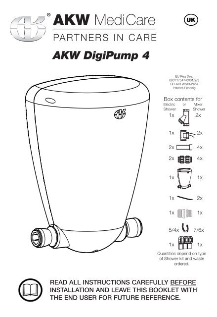
<strong>AKW</strong> <strong>MediCare</strong>PARTNERS IN CARE<strong>AKW</strong> DigiPump 4EU Reg Des:000717541-0001/2/3GB and World-WidePatents PendingBox contents forElectric or MixerShower Shower1x 2x1x2x2x2x4x4x1x1x1x1x2x1x5/4x 7/6x1x1xQuantities depend on typeof Shower kit and wasteordered.READ ALL INSTRUCTIONS CAREFULLY BEFOREINSTALLATION AND LEAVE THIS BOOKLET WITHTHE END USER FOR FUTURE REFERENCE.
ContentsPageProduct Specifications-Declaration of Conformity 2Important Safety and Electrical Information 3Mechanical and <strong>Plumb</strong>ing Installation 4-6Fixing pump to surface 7-8<strong>Plumb</strong>ing connections 9Fitting Flow Sensor(s) 10-11Electrical Installation 12-13Pump Set Up 14Commissioning 15Care and Maintenance 16Problem Solving 17WARRANTY 19Product Specifications<strong>AKW</strong> DigiPump 4 high performance shower waste water pump.Product CODE 25350PUMP CAPACITY -11LPM under free head/lift conditions.Derate accordingly for installed conditions.SUPPLY: 230V AC 50Hz 0.65A Max Head: 2.5m (98in).OUTPUT: 6-24V DC 3A 72VA Max Lift: 1.0m (39in).T5A fused internallyMAX COMBINED HEAD + LIFT:2.5m (98in)DUTY CYCLE: 30 mins max on 50% dutyQuiet in operation.For use with single supply, electric or mixer showers.Pump and controller enclosed in one unit.Max flow rate: 11 Litres Per Minute (LPM).Non-handed, selectable inlet/outlet direction.Declaration of ConformityWe declare that the <strong>AKW</strong> DigiPump 4 shower waste water pump conforms to the requirementsof the EMC Directive 89/336/EEC, Low Voltage Directive 73/23/EEC and the followingharmonised European and national standards in the confirming assessment.BS EN 61558-1, BS EN 61558-2-6, BS EN 60335-1, BS EN 60529,BS EN 60335-2-41<strong>AKW</strong> Medi-Care Ltd2KM50742
Important Safety/Electrical InformationTHIS CLASS II APPLIANCE DOES NOT REQUIRE AN EARTHCaution Danger of Death 230V ACLethal Voltage present on the AC supply.Ensure Mains Power Supply is Switched OFF before starting wiring.This product must be installed and serviced by a competent and qualifiedperson eg. NIC EIC in accordance with the current edition of the WiringRegulations BS7671 and the current Building Regulations.If the supply cord is damaged, it must be replaced by the manufacturerin order to avoid hazard.This product must be installed, used and maintained in good workingorder in accordance with these instructions and recommendations.DO NOT take risks with <strong>Plumb</strong>ing or Electrical Installation. Only a competentsuitably qualified NIC EIC trades person should attempt this electrical installation.The Digipump 4 shower waste water pump must be installed in accordance withthe current IEE wiring regulations (BS7671) and local by-laws. This product israted at IP45 and may be installed in Zone 1 or Zone 2 of a shower room only ifthese instructions are fully complied with.The 230V AC power supply to this unit must be provided via a two-pole isolatorswitch and a dedicated circuit with a 30mA RCD device installed in accordancewith the latest revision of the IEE Wiring Regulations BS7671.The IP45 rating of the <strong>AKW</strong> pump product refers to the inner casing containing theSELV electrical control gear. The pump motor which operates at SELV 24V DC(maximum) is located within the outer cover.The unit must be located away from the direct line of water jets wheneverpossible.Before you start...Confirm you have the required tools and parts.• Drill- Bits• Suitable wall plugs• Screwdriver(s)• Spirit Level• Pipe cutters (JG, TS)• 15mm Pipe/22mm Pipe• John Guest locking collarsJG PIPE CONNECTORS ARE NOTSUITABLE FOR CONNECTIONWITH CHROME OR STAINLESSPIPEWORK. CHROME PLATINGMUST BE REMOVED 20MMBEFORE JG FITTINGS ARECONNECTED TO PIPEWORK.3
Mechanical And <strong>Plumb</strong>ing InstallationPositioningThe DigiPump 4 shower waste water pump must be installed by a suitably qualified,competent person eg. NIC EIC, in accordance with current IEE Wiring Regulations(BS7671), building regulations and local by-laws.This product is rated at IP45 and is suitable for zones 1 and 2 of a shower roomonly if installed fully in accordance with these instructions.The unit must be located away from the direct line of water jets.Note: Zone 1 lies above zone 0 and below 2250mm (88in) vertically above a showertray or wet floor area.The perimeter of zone 1 of a wet floor (plan view) is within a 1.2 metres (47in) radiusof the shower head position. Consult BS7671 for further clarification.© 2008 <strong>AKW</strong> Medi-Care LimitedFOR GUIDANCE ONLY- PLEASE REFER TO BS7671 FOR FURTHER DETAILS4
Electric Shower InstallationFlow DirectionFit one flow sensor to coldwater-feed pipe12V DCSensor Cable230V ACSupplyEnsure Sensorcable is coveredby the suppliedinsulating sleevebefore connectingto mains supply.Fit Strainer before SensorCable routing andseparation mustconform to wiringRegs BS7671.Ensure Strainer is in aneasily accessible location.Ensure shower water supplypipework is flushed beforeconnecting to the showersensor via the strainer.15mm Pipework to Pump InletDigiPumpEnsure all cablesand plumbing arebehind waterresistant surface.22 mm OutletPipeworkMixer Shower InstallationFlow DirectionFit two Flow Sensors. One to hotand one to cold water-feed pipes12V DCSensor Cable230V ACSupplyEnsure Sensorcable is coveredby the suppliedinsulating sleevebefore connectingto mains supply.Fit Strainer before SensorCable routing andseparation mustconform to wiringRegs BS7671.Ensure Strainer(s) is in aneasily accessible location.Ensure shower water supplypipework is flushed beforeconnecting to the showersensor via the strainer.15mm Pipework to Pump InletDigiPump22 mm OutletPipeworkNote: REMOVE ALL BUILDING RUBBISH FROM TRAYOtherwise you will be called out again to clear pump blockages!5Ensure all cablesand plumbing arebehind waterresistant surface.
Fit pipe connections out of the box15mmwater flow direction (flow direction is reversible - see page 8 step 5)Assembled view:Section view:Note: REMOVE SHIPPING TAPES and screw both ends into place. No thread sealantneeded, firmly hand tighten only. Check that you have not overtightened and distortedthe valves before connecting the pipework.Inlet and outlet pipework connections must be a minimum of 100mm clear of theseconnections and suitable for pump removal and maintenance purposes.For Optimum PerformancePipe CutterJG TSSpeedfitPipeDO Cut plastic pipe using a pipe cutterDo NOT use a hacksaw to cut plastic pipeDo NOT use damaged pipeDo NOT use Speedfit ® pipe inserts on lowpressure lines as they create blockagesNote: JG PIPE CONNECTORS ARE NOT SUITABLE FOR CONNECTION WITH CHROME OR STAINLESSPIPEWORK. Remove any chrome plating on pipework of at least 20mm before inserting this typeof pipe into JG fittings.6
Fixing pump to surfaceImportant: For service & maintenance purposes this productmust be installed in an accessible location.Pipe connections must be easily accessible and a clearance of100mm around the base and sides is recommended.The pump unit must be located on a vertical surface with the inlet/outletconnections at the bottom of the unit in horizontal alignment, with the <strong>AKW</strong>case logo uppermost.The unit must be located away from the direct line of water jets whenever possible.DO NOT tile up to the pump unit on the wall, only fix onto surface.100mm (4in)1Remove front coverwith screwdriver.2Disconnect cable.Remove pump assemblyfrom the back plate toaccess fixing holes.3Using the back plate as atemplate mark the fixingholes. Drill & plug the walltaking care there are nohidden cables or pipes.Use all the screw fixingpositions.Fit to finished surface.Do not tile up to Pumpcase.7
4Mount pump to surfaceusing fixings.Use Pump Spacers toprevent the cables beingtrapped.See separate pumpspacers installationinstructions.5Check that the flow is in the required direction, reverse as required.6Refit the pump to theback plate.Reconnect cable.7Refit the front cover.8
<strong>Plumb</strong>ing ConnectionsThis Pump is rated for combined lift and head of 2.5m(98in) max.For best performance locate within 1m (39in) of showerand minimise the number of lifts, bends and the length ofall pipes connecting the Pump to the waste outlet pipe.Pump head should be 300mm (12in) for optimum performance.Shower Head100mm 100mm (4in) MIN GAPSWaste outletpipeMINHEADRECOMMENDEDShower TrayMINMINIMUMLENGTHLIFTMINIMISE PIPEWORK LENGTH WHEREVER POSSIBLEMINIMUMLENGTHNOTRECOMMENDED100mm MINUse the supplied PipeAdaptors to connectto waste outlet pipe.NOT PREFERREDPREFERRED (NO ELBOWS)MINImportant: For service & maintenance purposes this product must be installed in LIFT anaccessible location. Pipe connections must be easily accessed.Important: All external pipe connections must be at least 100mm (4in) clear and suitablefor pump removal.MINIMUMNEVER fit John Guest ® LENGTHPipe inserts. ALWAYS fit John Guest ® locking collars.MINMINIMUMLENGTHJohn Guest ® and Speedfit ® are registered trademarks of JohnGuest International Limited.9
Fitting Supply Flow Sensor To Electric ShowerThe electric shower has one supply line – cold water – fit one flow sensor to this line.Install the filter which is a Y-Pattern strainer, in the correct position to the shower water supplyline and then fit the flow sensor between the filter and the shower heater.NOTE: Direction of flow arrow moulded on casing is in the correct orientation.Connect the sensor cables from the flow sensor to the pump (see electrical installation).Ensure sensors and strainers are accessible for service and maintenance purposes.Vertical Cold Water FeedFit Flow Sensors betweenthe strainer and shower.Allow enough distance sothat the sensors are easilyaccessible.StrainerFlowDirectionCORRECT POSITIONWRONG POSITIONSENSOR CABLEFLOW SENSORCheck FlowDirectionSENSOR TAILConfirm shower water supply pipework isflushed before connecting to the showersensor via the strainer.Any building debris in the water supply to theshower heater will adversely affect the sensorfunction and may also damage the shower heater.Horizontal Cold Water FlowJG PUSH-FITSHOWERDO NOT tile over Flow Sensors.They must be accessible for servicing.SENSOR CABLEFILTER IN WRONG POSITIONFlowDirectionStrainerCORRECT POSITIONFailure to install the Strainer may invalidate any warranty for the product.Fit sensor “tails” using a WRC approved liquid based thread sealant suitable for nylon threads.10FLOW SENSORCheck Flow DirectionSHOWER
Fitting Supply Flow Sensor To Mixer ShowerThe Mixer shower has two supply lines – hot and cold water – fit one flow sensor to each line.Install the filter which is a Y-Pattern strainer, in the correct position to the shower water supplyline(s) and then fit the flow sensor between the filter and the shower heater.NOTE: Direction of flow arrow moulded on casing is in the correct orientation.Connect the sensor cables from each flow sensor to the pump. See electrical installation.Ensure sensors and strainers are accessible for service and maintenance purposes.Vertical FlowFit Flow Sensors betweenthe strainer and shower.Allow enough distance sothat the sensors are easilyaccessible.CORRECTPOSITIONStrainerFlowDirectionWRONG POSITIONFLOWSENSORConfirm shower water supply pipework isflushed before connecting to the showersensor via the strainer.Any building debris in the water supply to theshower heater will adversely affect the sensorfunction and may also damage the shower heater.Horizontal FlowSENSOR TAILJG PUSH-FITSHOWERDO NOT tile over Flow Sensors.They must be accessible for servicing.CheckFlowDirectionStrainerSENSOR CABLEFlowDirectionCORRECT POSITIONAll cable connections must be in a dry location.FLOW SENSORCheck Flow DirectionSHOWERFailure to install the Strainer may invalidate any warranty for the product.Fit sensor “tails” using a WRC approved liquid based thread sealant suitable for nylon threads.11
Electrical InstallationEnsure Mains Power Supply is Switched OFF before starting wiring.DO NOT take risks with <strong>Plumb</strong>ing or Electrical Installation.Only a competent trades person should attempt this installation.The DigiPump 4 shower waste pump must be installed in accordance with the current IEE wiring regulations(BS7671) and local by-laws. NIC EIC recommended.This product is rated at IP45 and may be installed in Zone 1 of a shower room only if the followingconditions are fully complied with:The pump unit must be located on a vertical surface with the inlet/outlet connections at the bottom of theunit in horizontal alignment, with the <strong>AKW</strong> case logo uppermost.The unit must be located away from the direct line of water jets whenever possible.Cable to and from the pump must be run directly out of zone 1 by the shortest route below the unit ordirectly behind into the vertical surface. All such routes must be sealed to prevent water ingress.Cables routed from above, down into the device, act as a drip path and should not be used.Cables must be protected against mechanical damage and sealed against water ingress.The case must not be cut except for the thin rear shroud. Do not pierce casing.The clearance behind the unit and separation from the wall must be maintained and the gap from case towall must not be sealed.The Pump Spacers kit suppiled can be used to route the cables behind and below the unit if required.See separate pump spacers installation instructions.All casing cable glands must be visually checked for presence of the elastomeric centre sealing grommetand tightness checked and confirmed before installing against the wall.No cable joints may be made in zone 1.The unit inner cover must not be disturbed and the outer cover must be correctly fitted.The 230V AC power supply to this unit must be provided via a two-pole isolator switch and adedicated circuit with a 30mA RCD device installed in accordance with the latest revision of theIEE Wiring Regulations BS7671.The IP45 rating of the <strong>AKW</strong> pump product refers to the inner casing containing the SELV electrical controlgear. The pump motor which operates at SELV 24V DC (maximum) is located within the outer cover.12
Electrical InstallationTHIS CLASS II APPLIANCE DOES NOT REQUIRE AN EARTHIsolating valveFlow SensorSensorcable45amp double poleisolating switchMains supply45amp doublepole isolatingswitchDigiPump 4Electric shower installation schematicFlow sensorcablesPower cableFlow Sensor Connections+ = Red - connect to flow sensor wire Red 1S = Brown - connect to flow sensor wire White 3- = Black - connect to flow sensor wire Black 2Any unused sensor wires must be terminated in a connector block and insulated using electrical insulationtape at a dry location. Failure to do this may damage the pump.Ensure the pump spacers are used to prevent the cables from being trapped.13Pump Spacers
Pump set upControl Button DescriptionTop Button = RUN (Sets shower stop run-on time)Centre Button = TEST (Calibration)Bottom Button = DELAY (Sets shower start delay to run)TestWhen power is supplied to the pump the upper run LED (yellow) should glow indicating a voltage present,and the digital display will show the run on timer setting in seconds (factory set is 20).Press the TEST button. The digital display will show the start delay in seconds (factory set is 5) and thebottom LED will flash and start the following test sequence:-Test sequence once button is pressed1. Start delay timer counts down. (bottom LED flashing)2. The pump runs with top LED flashing and the display shows the time to run.3. The display returns to the set run on time.This test can be carried out with or without water present and also the sensor plug fitted or not.CalibrationThe DigiPump 4 allows for precise pump control of the shower water by calculating the amount of waterthe shower is producing. It may be necessary to adjust the pump once installation is complete. (the pumpmay be over or under pumping).To calibrate the pump and compensate for this, press and hold the TEST button for around 5 seconds,until both LEDs flash. The pump is now in calibration mode. The display shows the factory calibration valuestored (default is 50).This can be adjusted using the RUN button (up) and the DELAY button (down). The value can be adjustedfrom 0-99.Run the shower at the expected normal flow rate. The pump must run at a speed which removes the sameamount of water as is flowing in.Adjust the calibration value so the water level stays approximately the same. If the water level drops,decrease the value on the display so the pump runs slower. If the water level rises, increase the value onthe display so the pump runs faster. When the value is set correctly, press the test button to store. Thecontroller will then return to its normal operating mode.Timer AdjustmentWith the pump in normal operating mode and the LED showing the run on time:Adjust Run on time. (the time the pump will run after the shower has stopped)Press the RUN button: this will increase the time by 1 second, holding the button will increase the timerapidly, once the time reaches 99 it will roll over to 01.Start Delay (the time before the pumps starts after the shower is operating)Press the DELAY button: this will increase the time by 1 second, holding the button will increase the timerapidly, once the time reaches 99 it will roll over to 01.14
Commissioning ChecksAs a general precaution and check before installation, always ensure the supply pipework to theshower has been fully purged with at least 20 litres (2 buckets) of water through it before the flowsensor or shower water heater are fitted. Any building debris in the water supply to the showerheater will adversely affect the sensor function and may also damage the shower heater.Install Pump according to these instructions. Failure to do so will void warranty.Confirm all push-fit pipes are fully inserted 20mm into fittings.Brush out all dust, grit and debrisfrom shower trayThoroughly clean out wasteConfirm shower water supply pipework is flushedbefore connecting to the shower sensor via thestrainerTurn on power to PumpTurn shower on Low Flow and confirm pumpoperates after approx 5 secs. Run for 2-3 minsSet shower to Maximum FlowFollow the Calibration setting, adjust pump speedon controller to match maximum shower flowAdjust RUN-ON and repeat until tray is clearedand pump stops with minimum RUN-ONSwitch shower OFF.Pump will RUN-ONIf you experience problems seeProblem Solving section15
Care and MaintenanceThe integrity of the case and the RCD device operation must be checked quarterlyas part of a routine safety and maintainance activity on the installation.If the case shows any mechanical damage the unit must be isolated electrically andthe entire unit replaced.Pipework connections must be made to the unit with sufficient clearance (100mmminimum separation to any pipe bend or fitting adjacent to the inlet/outletconnections) to permit removal of the pump/head for routine maintenance andreplacement.The unit must be regularly cleaned using normal bathroom cleaning materials andrinsed down with clean water and wiped dry to remove any cleaning residue.Problem solvingPUMP WILL NOT STARTPlease refer to pump instructions to ensure the pump is installedcorrectly.Ensure flow sensor is connected to pump controller and power ison to pump controller.Ensure that all pipe work is fully flushed before the flow sensor isinstalled, and the in-line strainer is in place.Check flow sensor is installed in right orientation(Flow direction arrow moulded on the casing).Most flow sensor problems are due to debris being caught insidethe flow sensor. Remove sensor and check for debris.If required reverse flush with water.16
Problem solvingPUMP WILL STARTBUT NOT PUMP WATERCheck Non-Return Valves are fittedin inlet and outlet.Confirm plastic pipe inserts areNOT used.(see page 1 of instructions)Ensure all push-fit pipe connections are fully sealed and O-rings are notdamaged or displaced.The water pumping capacity can be adjusted by adjusting pump speed.Adjust pump speed using the calibration setting.Please refer to instructions overleafWhen increasing the pump speed*, if the pump still performs low or nosuction, take off the pump head by removing the clamp ring. Examine theinlet and outlet flap valves for traces of hard debris such as grit.If so, wash out all debris and ensure thevalves are seated correctly.If problem persists, check all connections for air leaks or blockage ineither the inlet or outlet pipework. Repair any leaks or clean blockages.PUMP WILL NOT STOPThe pump has an overrun timer to allow it to continue to run after theshower has been switched off. This timer is factory set to 20 seconds.With the power supply switched on, disconnect the flow sensor. Separatethe disconnected wires. This will simulate the flow sensor turning off.Pump should stop after the overrun time. If not, check the controllerand/or cabling and replace it as necessary.If controller is OK, remove and check the flow sensor, flush it through withwater or replace it as necessary.* Please See Pump Set Up17
To be completed by Installer<strong>AKW</strong> <strong>MediCare</strong>PARTNERS IN CAREProduct Identification labelcan be found on the pump caseand also on the outer packaging.Model/Part NumberPump Serial Number (SN)Batch number (BN)INSTALLED ONINSTALLED BYADDRESSCONTACTPlease complete the registration card within 30 days and return to us inthe prepaid envelope for your Free Warranty to start.<strong>AKW</strong> Medi-Care Limited, Pointon Way, Hampton Lovett, Droitwich Spa, WR9 0LRTel:+44 (0) 1905 823 298 - Fax: +44 (0) 1905 823 297
This Warranty is in addition to your statutory and other legal rights.To validate and start the Warranty, you must return your completed registration card.<strong>AKW</strong> Medi-Care Ltd Warranty Covers your shower water waste pump against anydefect in materials or workmanship for 5 years from the date of installation. Within thisperiod we will resolve defects free of charge by repairing or replacing as we maychoose. To be free of charge work must be only undertaken by <strong>AKW</strong> or our approvedagents in the UK, Northern Ireland or the Republic of Ireland and with prior agreement.Any action taken under this guarantee does not extend the stated 5-year expiry date.NOT COVERED BY THIS WARRANTYDamage or defects arising from incorrect installation,improper use or lack ofmaintenance including the build-up of limescale.Actions taken to dismantle, repair or modify beyond that shown in this installationguide, by persons who are not <strong>AKW</strong> Medi-Care Ltd authorised service staff or agents.Damage resulting from water freezingWARRANTYBEFORE USING YOUR SHOWER WASTE PUMPPlease take time to read and understand the operating and safety instructions detailedin this manual.WHAT TO DO IF SOMETHING GOES WRONGIf your shower does not work correctly first follow the Problem solving chart onpage 16, then contact your installer.Should this not resolve your problem, contact <strong>AKW</strong> Customer Services who willprovide further advice and if necessary arrange for our service engineer to visit, ordiscuss our comprehensive after-sales service. As part of our quality and trainingprogram calls may be monitored or recorded.None of the forgoing affects your statutory rights.As part of our on-going improvement programme, <strong>AKW</strong> Medi Care would appreciateany feedback on these instructions.If you have any comments please contact us on Tel:+44 (0) 01905 823235<strong>AKW</strong> Medi-Care Limited, Pointon Way, Hampton Lovett, Droitwich Spa, WR9 0LRTel:+44 (0) 1905 823 298 - Fax: +44 (0) 1905 823 297© 2009 <strong>AKW</strong> Medi-Care Limited www.akw-medicare.co.uk 07-001-047-02
<strong>AKW</strong> <strong>MediCare</strong>PARTNERS IN CAREImportant Safety InformationDANGER OF DEATH! 230V ACLethal Voltage present on the AC supply to the pump inner case.This unit must be connected to a 13A fused double-poleswitched supply provided with a RDC protection..Isolate this unit before access for maintenance or any otherpurpose.Do not immerse in water.No user serviceable parts within case. The cover must onlybe removed by an authorised service person or electrician.This product must be installed by a qualified and competentelectrician and in accordance with the current edition of theWiring Regulations BS7671. This appliance must be located tocomply with the safety zones as defined in the wiringregulations.<strong>AKW</strong> Medi-Care Limited, Pointon Way, Hampton Lovett, Droitwich Spa, WR9 0LRTel:+44 (0) 1905 823 298 - Fax: +44 (0) 1905 823 297© 2009 <strong>AKW</strong> Medi-Care Limited www.akw-medicare.co.uk 07-001-047-02