GREENSTAR CDi CLASSIC - Plumb Traders
GREENSTAR CDi CLASSIC - Plumb Traders
GREENSTAR CDi CLASSIC - Plumb Traders

Create successful ePaper yourself
Turn your PDF publications into a flip-book with our unique Google optimized e-Paper software.
INSTALLATION COMMISSIONING AND SERVICING INSTRUCTIONS<br />
WALL HUNG RSF GAS FIRED CONDENSING COMBINATION BOILER<br />
<strong>GREENSTAR</strong> <strong>CDi</strong> <strong>CLASSIC</strong><br />
FOR SEALED CENTRAL HEATING SYSTEMS AND MAINS FED DOMESTIC HOT WATER<br />
The appliances are for use with:<br />
Natural Gas or L.P.G. (Cat. II type C13, C33)<br />
Natural Gas: 29<strong>CDi</strong> GC number 47-406-34<br />
34<strong>CDi</strong> GC number 47-406-36<br />
38<strong>CDi</strong> GC number 47-406-38<br />
42<strong>CDi</strong> GC number 47-406-10<br />
L.P.G.: 29<strong>CDi</strong> GC number 47-406-35<br />
34<strong>CDi</strong> GC number 47-406-37<br />
38<strong>CDi</strong> GC number 47-406-39<br />
42<strong>CDi</strong> GC number 47-406-11<br />
UK/IE<br />
6 720 803 599 (2012/06)
CONTENTS<br />
CONTENTS<br />
1 KEY TO SYMBOLS . . . . . . . . . . . . . . . . . . . . . . . . . . . . . . . . . . . . . 3<br />
1.1 Key to symbols . . . . . . . . . . . . . . . . . . . . . . . . . . . . . . . . . 3<br />
1.2 Safety precautions . . . . . . . . . . . . . . . . . . . . . . . . . . . . . . 3<br />
2 APPLIANCE INFORMATION . . . . . . . . . . . . . . . . . . . . . . . . . . . . . 5<br />
2.1 General information . . . . . . . . . . . . . . . . . . . . . . . . . . . . . 5<br />
2.2 Layout & components . . . . . . . . . . . . . . . . . . . . . . . . . . . . 6<br />
2.3 Technical data . . . . . . . . . . . . . . . . . . . . . . . . . . . . . . . . . . 8<br />
3 PRE-INSTALLATION . . . . . . . . . . . . . . . . . . . . . . . . . . . . . . . . . . . . 9<br />
3.1 Cleaning primary systems . . . . . . . . . . . . . . . . . . . . . . . . . 9<br />
3.2 Mains supply . . . . . . . . . . . . . . . . . . . . . . . . . . . . . . . . . . . 9<br />
3.2.1 Electrical supply . . . . . . . . . . . . . . . . . . . . . . . . . . . . . . . . 9<br />
3.2.2 Gas supply . . . . . . . . . . . . . . . . . . . . . . . . . . . . . . . . . . . . . 9<br />
3.2.3 Water supply . . . . . . . . . . . . . . . . . . . . . . . . . . . . . . . . . . . 9<br />
3.3 Water systems and pipe work . . . . . . . . . . . . . . . . . . . . 10<br />
3.4 Condensate pipe work . . . . . . . . . . . . . . . . . . . . . . . . . 11<br />
3.4.1 Internal connections . . . . . . . . . . . . . . . . . . . . . . . . . . . 11<br />
3.4.2 External connections . . . . . . . . . . . . . . . . . . . . . . . . . . 12<br />
3.5 Pressure relief pipe work . . . . . . . . . . . . . . . . . . . . . . . 13<br />
3.6 Boiler location & clearances . . . . . . . . . . . . . . . . . . . . . 13<br />
3.7 <strong>Plumb</strong>ing manifold . . . . . . . . . . . . . . . . . . . . . . . . . . . . 15<br />
3.8 Flue options . . . . . . . . . . . . . . . . . . . . . . . . . . . . . . . . . . 16<br />
3.9 Flue terminal positions . . . . . . . . . . . . . . . . . . . . . . . . . 18<br />
3.10 Plume management terminal positions . . . . . . . . . . . . 19<br />
6 SERVICING AND SPARES . . . . . . . . . . . . . . . . . . . . . . . . . . . . . . 35<br />
6.1 Inspection and service . . . . . . . . . . . . . . . . . . . . . . . . . . 35<br />
6.1.1 Component access . . . . . . . . . . . . . . . . . . . . . . . . . . . . . 35<br />
6.1.2 Fan pressure test . . . . . . . . . . . . . . . . . . . . . . . . . . . . . . 36<br />
6.1.3 To Clean the Heat Exchanger . . . . . . . . . . . . . . . . . . . . . 37<br />
6.1.4 To Clean the Burner . . . . . . . . . . . . . . . . . . . . . . . . . . . . 37<br />
6.1.5 To Check the Diaphragm in Burner Cover . . . . . . . . . . . 38<br />
6.1.6 To Clean the Condensate Trap . . . . . . . . . . . . . . . . . . . . 38<br />
6.2 Setting the air/gas ratio . . . . . . . . . . . . . . . . . . . . . . . . . 38<br />
6.3 Replacement of parts . . . . . . . . . . . . . . . . . . . . . . . . . . . 39<br />
6.4 Short parts list . . . . . . . . . . . . . . . . . . . . . . . . . . . . . . . . . 48<br />
7 FAULT FINDING & DIAGNOSIS . . . . . . . . . . . . . . . . . . . . . . . . . 49<br />
7.1 Fault finding . . . . . . . . . . . . . . . . . . . . . . . . . . . . . . . . . . 49<br />
7.2 Central heating function . . . . . . . . . . . . . . . . . . . . . . . . . 50<br />
7.3 Preheat and DHW function . . . . . . . . . . . . . . . . . . . . . . . 51<br />
7.4 Protection function . . . . . . . . . . . . . . . . . . . . . . . . . . . . . 52<br />
4 INSTALLATION . . . . . . . . . . . . . . . . . . . . . . . . . . . . . . . . . . . . . . 20<br />
4.1 Unpacking wall frame and ancillary items . . . . . . . . . . 20<br />
4.2 Wall mounting plate flue opening . . . . . . . . . . . . . . . . . 21<br />
4.3 Charging link (filling loop) . . . . . . . . . . . . . . . . . . . . . . . 22<br />
4.4 Unpacking the appliance . . . . . . . . . . . . . . . . . . . . . . . 23<br />
4.5 Fitting the appliance/boiler connections . . . . . . . . . . . 24<br />
4.6 Flue installation . . . . . . . . . . . . . . . . . . . . . . . . . . . . . . . 25<br />
4.6.1 Ø60/100mm Telescopic flue kit: . . . . . . . . . . . . . . . . . 25<br />
4.6.2 Ø60mm Plume management kit: . . . . . . . . . . . . . . . . . 25<br />
4.6.3 Adjusting the standard terminal length: . . . . . . . . . . . 25<br />
4.6.4 Installing the standard flue . . . . . . . . . . . . . . . . . . . . . . 26<br />
4.6.5 Flue terminal plume re-direction: . . . . . . . . . . . . . . . . . 26<br />
4.7 Condensate connection . . . . . . . . . . . . . . . . . . . . . . . . 27<br />
4.8 Electrical . . . . . . . . . . . . . . . . . . . . . . . . . . . . . . . . . . . . 28<br />
4.9 Position of wired components . . . . . . . . . . . . . . . . . . . 29<br />
5 COMMISSIONING . . . . . . . . . . . . . . . . . . . . . . . . . . . . . . . . . . . 30<br />
5.1 Pre-commissioning checks . . . . . . . . . . . . . . . . . . . . . . 30<br />
5.2 Filling the system . . . . . . . . . . . . . . . . . . . . . . . . . . . . . . 30<br />
5.3 Starting the appliance . . . . . . . . . . . . . . . . . . . . . . . . . . 31<br />
5.4 Water treatment . . . . . . . . . . . . . . . . . . . . . . . . . . . . . . 32<br />
5.5 Commissioning . . . . . . . . . . . . . . . . . . . . . . . . . . . . . . . 32<br />
5.5.1 Checking the gas inlet pressure . . . . . . . . . . . . . . . . . . 32<br />
5.5.2 Checking the gas rate . . . . . . . . . . . . . . . . . . . . . . . . . . 33<br />
5.5.3 Domestic hot water: . . . . . . . . . . . . . . . . . . . . . . . . . . . 33<br />
5.5.4 Domestic hot water pre-heat: . . . . . . . . . . . . . . . . . . . . 33<br />
5.6 Finishing commissioning . . . . . . . . . . . . . . . . . . . . . . . 34<br />
2<br />
6 720 803 599 (2012/06)
KEY TO SYMBOLS<br />
1 KEY TO SYMBOLS<br />
1.1 KEY TO SYMBOLS<br />
WARNINGS<br />
Warnings in this document are identified by a warning<br />
triangle printed against a grey background.<br />
Keywords at the start of a warning indicate the type and<br />
seriousness of the ensuing risk if measures to prevent<br />
the risk are not taken.<br />
The following keywords are defined and can be used in this document:<br />
• NOTE indicates a situation that could result in damage to property or<br />
equipment.<br />
• CAUTION indicates a situation that could result in minor to medium<br />
injury.<br />
• WARNING indicates a situation that could result in severe injury or<br />
death.<br />
• DANGER indicates a situation that will result in severe injury or death.<br />
IMPORTANT INFORMATION<br />
This symbol indicates important information where<br />
there is no risk to people or property.<br />
ADDITIONAL SYMBOLS<br />
Symbol Explanation<br />
B Step in an action sequence<br />
Cross-reference to another part of the document<br />
• List entry<br />
– List entry (second level)<br />
SYMBOLS USED IN THIS MANUAL<br />
Domestic Hot Water<br />
Central Heating<br />
Hot Water Storage Cylinder<br />
Domestic Cold Water Supply<br />
Electrical Supply<br />
Gas Supply<br />
Table 1 Commonly used symbols<br />
PLEASE READ THESE INSTRUCTIONS CAREFULLY BEFORE<br />
STARTING INSTALLATION.<br />
These instructions are applicable to the Worcester appliance model(s)<br />
stated on the front cover of this manual only and must not be used with<br />
any other make or model of appliance.<br />
These instructions apply in the UK and Ireland only and must be<br />
followed except for any statutory obligations.<br />
This appliance must be installed by a GAS SAFE registered,<br />
competent person. Failure to install correctly could lead to<br />
prosecution.<br />
If you are in any doubt, contact the Worcester Technical helpline<br />
(0844 892 3366).<br />
Please leave these instructions with the completed BENCHMARK<br />
CHECKLIST, (or a certificate confirming compliance with IS 813, Eire<br />
only) and the user manual with the owner or at the gas meter after<br />
installation or servicing.<br />
Distance learning and training courses are available from Worcester.<br />
The BENCHMARK CHECKLIST can be found in the back of this<br />
Installation manual.<br />
Ø<br />
Diameter<br />
NG<br />
Natural Gas<br />
LPG<br />
Liquid Petroleum Gas<br />
CH<br />
Central Heating<br />
DHW Domestic Hot Water<br />
DCW Domestic Cold Water<br />
PRV<br />
Pressure Relief Valve<br />
NTC<br />
Negative Temperature Coefficient (sensor)<br />
IP<br />
Ingress Protection<br />
RCD<br />
Residual Current Device<br />
TRV<br />
Thermostatic Radiator Valve<br />
ECV<br />
Emergency Control Valve<br />
WRAS Water Regulations Advisory Scheme<br />
SEDBUK Seasonal Efficiency of Domestic Boilers in the United<br />
Kingdom<br />
Table 2 Abbreviations use in this manual<br />
1.2 SAFETY PRECAUTIONS<br />
IF YOU SMELL GAS:<br />
B TURN OFF THE ECV (EMERGENCY CONTROL VALVE) AT THE METER/<br />
REGULATOR<br />
B DO NOT TURN ELECTRICAL SWITCHES ON OR OFF<br />
B DO NOT STRIKE MATCHES OR SMOKE<br />
B PUT OUT NAKED FLAMES<br />
B OPEN DOORS AND WINDOWS<br />
B KEEP PEOPLE AWAY FROM THE AFFECTED AREA<br />
B CALL NATIONAL GAS EMERGENCY SERVICE ON 0800 111 999<br />
B LPG BOILERS CALL THE SUPPLIER'S NUMBER ON THE SIDE OF THE<br />
LPG TANK<br />
BOILER OPERATION:<br />
This boiler must only be operated by a responsible adult who has<br />
been instructed in, understands, and is aware of the boiler's<br />
operating conditions and effects.<br />
Benchmark places<br />
responsibilities on both<br />
manufacturers and installers.<br />
The purpose is to ensure that<br />
customers are provided with the correct equipment for their needs, that<br />
it is installed, commissioned and serviced in accordance with the<br />
6 720 803 599 (2012/06) 3
KEY TO SYMBOLS<br />
manufacturer's instructions by competent persons and that it meets the<br />
requirements of the appropriate Building Regulations.<br />
The Benchmark Checklist can be used to demonstrate compliance with<br />
Building Regulations and should be provided to the customer for future<br />
reference.<br />
The guarantee of this product is dependant on the Benchmark checklist<br />
being completed and the actions undertaken.<br />
Installers are required to carry out installation, commissioning and<br />
servicing work in accordance with the Benchmark Code of Practice<br />
which is available from the Heating and Hot water Industry Council who<br />
manage and promote the scheme.<br />
Visit centralheating.co.uk for more information.<br />
HEALTH AND SAFETY<br />
The appliance contains no asbestos and no substances have been used<br />
in the construction process that contravene the COSHH Regulations<br />
(Control of Substances Hazardous to Health Regulations 1988).<br />
COMBUSTION AND CORROSIVE MATERIALS<br />
Do not store or use any combustible materials (paper, thinners, paints<br />
etc.) inside or within the vicinity of the appliance.<br />
Chemically aggressive substances can corrode the appliance and<br />
invalidate any guarantee.<br />
FITTING AND MODIFICATIONS<br />
Fitting the appliance and any controls to the appliance may only be<br />
carried out by a competent engineer in accordance with the current Gas<br />
Safety (Installation and Use) Regulations.<br />
Flue systems must not be modified in any way other than as described in<br />
the fitting instructions. Any misuse or unauthorised modifications to the<br />
appliance, flue or associated components and systems could invalidate<br />
the guarantee. The manufacturer accepts no liability arising from any<br />
such actions, excluding statutory rights.<br />
SERVICING<br />
Advise the user to have the system serviced annually by a competent,<br />
qualified Gas Safe registered engineer. Approved spares must be used<br />
to help maintain the economy, safety and reliability of the appliance.<br />
IMPORTANT<br />
The service engineer must complete the Service Record on the<br />
Benchmark Checklist after each service.<br />
INSTALLATION REGULATIONS<br />
Current Gas Safety (Installation & Use) Regulations:<br />
All gas appliances must be installed by a competent person in<br />
accordance with the above regulations.<br />
Failure to install appliances correctly could lead to prosecution.<br />
The appliance must be installed in accordance with, and comply to, the<br />
current: Gas Safety Regulations, IEE Regulations, Building Regulations,<br />
Building Standards (Scotland) (Consolidation), Building Regulations<br />
(Northern Ireland), local water by-laws, Health & Safety Document 635<br />
(The Electricity at Work Regulations 1989) and any other local<br />
requirements.<br />
BUILDING REGULATIONS PART L 1A 2010<br />
If the installation is in a new build property or is a first time installation in<br />
an existing property, heating systems must conform to current building<br />
regulations Part L1a.<br />
All new heating systems in dwellings must have at least two heating<br />
zones. Each of these zones will be operated separately by both time and<br />
temperature controls.<br />
The exception to this are single storey, open plan dwellings where the<br />
living area is more than 70% of the total useable floor area. Then this<br />
type of dwelling can be controlled as one zone.<br />
All radiators must have TRVs fitted, where reasonable, in all rooms<br />
except bathrooms and rooms with thermostats.<br />
BUILDING REGULATIONS PART L 1B 2010 - BOILER REPLACEMENT<br />
For boiler replacement on an existing system, it is not necessary to zone<br />
the system, compliance with the zone requirements can be achieved by<br />
a single room thermostat or programmable room thermostat.<br />
BRITISH STANDARDS<br />
Where no specific instruction is given, reference should be made to the<br />
relevant British Standard codes of Practice.<br />
BS7074:1 Code of practice for domestic and hot water supply<br />
BS6891 Installation of low pressure gas pipe work up to 35mm (R1¼ )<br />
BS5546 Installation of gas hot water supplies for domestic purposes<br />
EN12828 Central heating for domestic premises<br />
BS5440:1 Flues and ventilation for gas appliances of rated heating not<br />
exceeding 70kW (net) : Flues<br />
BS5440:2 Flues and ventilation for gas appliances of rated heating not<br />
exceeding 70kW (net) : Air Supply<br />
BS7593 Treatment of water in domestic hot water central heating<br />
systems<br />
BS6798 Installation of gas fired boilers of rated input up to 70kW (net)<br />
Irish Standards<br />
The relevant Irish standards should be followed, including:<br />
• ECTI National rules for electrical installations<br />
• IS 813:2002 for Domestic Gas Installations.<br />
LPG Installations<br />
An appliance using L.P.G. must not be installed in a room or internal<br />
space below ground level unless one side of the building is open to the<br />
ground.<br />
Timber framed building:<br />
Where the boiler is to be fitted to a timber framed building the guidelines<br />
laid down in BS5440: Part 1 and IGE "Gas Installations in Timber Frame<br />
Buildings” should be adhered to.<br />
Potable water:<br />
All seals, joints and compounds (including flux and solder) and<br />
components used as part of the secondary domestic water system must<br />
be approved by WRAS.<br />
CH Water:<br />
Artificially softened water must not be used to fill the central heating<br />
system.<br />
BOILER FEATURES<br />
• Pre-wired and pre-plumbed<br />
• Galvanised steel inner frame<br />
• Digital control system<br />
• FX Intelligent controls<br />
• Automatic ignition<br />
• Direct burner ignition electrodes<br />
• Built-in frost protection<br />
• Built-in fault finding diagnostics<br />
• Automatic gas valve<br />
• Modulating combustion air fan with speed regulator<br />
• CH temperature sensor & control<br />
• Pump anti-seizure protection<br />
• Flue gas temperature sensor<br />
• Condensate siphonic trap<br />
• DHW flow sensor & temperature control<br />
• Plate type DHW heat exchanger<br />
• Modulating circulating pump<br />
• Optional cross bonding strip available<br />
– Part number 7 716 192 686<br />
4<br />
6 720 803 599 (2012/06)
APPLIANCE INFORMATION<br />
2 APPLIANCE INFORMATION<br />
2.1 GENERAL INFORMATION<br />
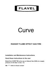
STANDARD PACKAGE:<br />
A<br />
Wall hung gas fired condensing combi boiler for central<br />
heating and domestic hot water<br />
B<br />
Wall mounting plate<br />
C<br />
Hanging bracket<br />
D<br />
Pre-plumbing manifold<br />
E<br />
Hardware pack<br />
F<br />
Charging Link Assembly<br />
G<br />
Literature pack<br />
H<br />
Bottom panel<br />
I<br />
Trap / Siphon Outlet Connection<br />
(22 mm Plastic Pipe)<br />
C<br />
B<br />
max.<br />
360 mm<br />
A<br />
D<br />
I<br />
E<br />
F<br />
G<br />
max.<br />
760 mm<br />
6720647631-02.1Wo<br />
Fig. 2<br />
Standard package<br />
6720647361-01.3Wo<br />
440mm<br />
H<br />
Fig. 1<br />
Overall dimensions<br />
6 720 803 599 (2012/06) 5
APPLIANCE INFORMATION<br />
2.2 LAYOUT & COMPONENTS<br />
29<br />
1<br />
28<br />
2<br />
3<br />
27<br />
4<br />
26<br />
5<br />
25<br />
24<br />
6<br />
23<br />
22<br />
21<br />
20<br />
19<br />
7<br />
8<br />
9<br />
10<br />
11<br />
18<br />
17<br />
16<br />
12<br />
13<br />
14<br />
15<br />
6720647361-03.1Wo<br />
Fig. 3<br />
Boiler components<br />
6<br />
6 720 803 599 (2012/06)
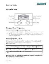
APPLIANCE INFORMATION<br />
The diagram opposite shows the controls in the servicing position<br />
and excludes the outer case<br />
1 FLAME VIEWING WINDOW<br />
2 IGNITION ELECTRODES AND FLAME SENSE ELECTRODE<br />
3 HEAT EXCHANGER<br />
4 OVERHEAT THERMOSTAT<br />
5 ACCESS POINT FOR CLEANING HEAT EXCHANGER<br />
6 PLATE TO PLATE DHW HEAT EXCHANGER<br />
7 MODULATING PUMP<br />
8 PRESSURE RELIEF VALVE<br />
9 DRAIN POINT<br />
10 DCW MAINS ISOLATING VALVE<br />
11 CH RETURN ISOLATING VALVE<br />
12 CHARGING LINK ASSEMBLY<br />
13 COVER FOR EXTERNAL WIRING CONNECTIONS<br />
14 CONTROL PANEL IN SERVICE POSITION<br />
15 SYSTEM PRESSURE GAUGE<br />
16 GAS ISOLATING VALVE<br />
17 DHW OUTLET CONNECTION<br />
18 CH FLOW ISOLATING VALVE<br />
19 CONDENSATE DRAIN CONNECTION<br />
20 CONDENSATE SIPHON<br />
21 INLET PRESSURE TEST POINT<br />
22 GAS VALVE<br />
23 DHW TEMPERATURE SENSOR (NTC)<br />
24 AIR / GAS - ADJUST MAXIMUM SETTING SCREW<br />
25 FAN PRESSURE TEST POINT<br />
26 FAN<br />
27 PRIMARY SENSOR<br />
28 EXPANSION VESSEL<br />
29 REMOVABLE TOP CASE PANEL FOR SERVICING<br />
Table 3 Main boiler components<br />
42<br />
35<br />
6<br />
34<br />
33<br />
32<br />
31<br />
30<br />
7<br />
49<br />
48<br />
47<br />
46<br />
43<br />
44<br />
Fig. 5<br />
2<br />
1<br />
Control panel<br />
3 4<br />
5<br />
6<br />
max<br />
6720647361-56.2Wo<br />
30 FLOW TURBINE<br />
31 UNUSED PORT<br />
32 RETURN CONNECTION TO BOILER HEAT EXCHANGER<br />
33 AUTO AIR VENT<br />
34 EXPANSION VESSEL CONNECTION<br />
35 FLOW CONNECTION FROM BOILER HEAT EXCHANGER<br />
36 DHW SENSOR<br />
37 CH FLOW CONNECTION TO PRE-PLUMBING MANIFOLD<br />
38 DHW OUT CONNECTION TO PRE-PLUMBING MANIFOLD<br />
39 DCW IN CONNECTION FROM PRE-PLUMBING MANIFOLD<br />
40 CH RETURN CONNECTION FROM PRE-PLUMBING MANIFOLD<br />
41 DIVERTER VALVE<br />
42 COMPACT HYDRAULIC MOUNTING SCREW (2) TO BOILER<br />
43 CH TEMPERATURE CONTROL<br />
44 MAINS ON/OFF INDICATOR/DIAGNOSTIC LIGHT (BLUE)<br />
45 DHW TEMPERATURE CONTROL<br />
46 PERFORMANCE TEST BUTTON<br />
47 SERVICE BUTTON<br />
48 BURNER ON INDICATOR LIGHT (GREEN)<br />
49 MASTER SWITCH ON/OFF<br />
50 HOLIDAY BUTTON<br />
51 ECO BUTTON<br />
52 FAULT RESET BUTTON<br />
53 DISPLAY<br />
54 POSITION FOR OPTIONAL PLUG-IN CONTROL<br />
Table 4 Hydraulics and control panel<br />
1<br />
2<br />
min<br />
3 4<br />
54 53<br />
e<br />
6<br />
max<br />
reset<br />
eco<br />
2<br />
1 3<br />
0 bar 4<br />
15<br />
52<br />
51<br />
50<br />
45<br />
42<br />
36<br />
8<br />
41<br />
Fig. 4<br />
37 38<br />
Hydraulics<br />
39<br />
9<br />
40<br />
6720647361-04.2Wo<br />
6 720 803 599 (2012/06) 7
APPLIANCE INFORMATION<br />
2.3 TECHNICAL DATA<br />
NATURAL GAS<br />
L.P.G<br />
DESCRIPTION UNITS 29 34 38 42 29 34 38 42<br />
Domestic hot water<br />
Min. heat input kW 8.0 8.0 9.8 9.8 11.5 11.5 14.5 14.5<br />
Max. rated heat output kW 30.9 35.0 40.0 42.0 30.9 35.0 40.0 42.0<br />
Max. rated heat input kW 30.9 35.0 40.0 42.0 30.9 35.0 40.0 42.0<br />
Max. mains inlet pressure bar 10 10 10 10 10 10 10 10<br />
Min. mains inlet pressure (working) for max flow bar 1.4 1.5 1.7 1.9 1.4 1.5 1.7 1.9<br />
Min. mains inlet pressure (working) for<br />
bar 0.2 0.2 0.2 0.2 0.2 0.2 0.2 0.2<br />
operation<br />
DHW temperature range °C 40-60 40-60 40-60 40-60 40-60 40-60 40-60 40-60<br />
DHW specific rate - 30°C rise l/min 14.8 16.7 19.1 20.1 14.8 16.7 19.1 20.1<br />
Max. DHW flow rate - 40°C rise ± 15% l/min 11 12 14 15 11 12 14 15<br />
Central Heating<br />
Max. rated heat input kW 30.9 30.9 30.9 30.9 30.9 30.9 30.9 30.9<br />
Max. rated heat output net 40/30°C kW 32.1 32.1 32.1 32.1 32.1 32.1 32.1 32.1<br />
Max. rated heat output net 50/30°C kW 31.8 31.8 31.8 31.8 31.8 31.8 31.8 31.8<br />
Max. rated heat output net 80/60°C kW 30.0 30.0 30.0 30.0 30.0 30.0 30.0 30.0<br />
Min. rated heat output net 40/30°C kW 8.6 8.6 10.6 10.6 8.6 12.4 15.7 15.7<br />
Min. rated heat output net 50/30°C kW 8.6 8.6 10.5 10.5 8.6 12.3 15.5 15.5<br />
Min. rated heat output net 80/60°C kW 7.7 7.7 9.4 9.4 7.7 11.0 13.9 13.9<br />
Min. rated heat input net kW 8.0 8.0 9.8 9.8 8.0 11.5 14.5 14.5<br />
Max. flow temperature (nominal) °C 90 90 90 90 90 90 90 90<br />
Max. permissible operating pressure bar 3.0 3.0 3.0 3.0 3.0 3.0 3.0 3.0<br />
Available pump head at 21°C system temp. rise m 2 2 2 2 2 2 2 2<br />
Gas flow rate - Max. 10 minutes from lighting<br />
Natural Gas G20 m3/h 3.3 3.7 4.2 4.4 - - -<br />
Propane Gas (LPG) kg/h - - - 2.4 2.7 3.1 3.3<br />
Flue<br />
Flue Gas Temp. 80/60°C, rated min. load °C 76/58 81/58 83/58 86/58 76/58 81/58 86/58 87/58<br />
Flue Gas Temp. 40/30°C, rated min. load °C 55/33 58/33 65/35 66/35 55/33 58/33 65/35 66/35<br />
CO 2 level at max. rated heat output % 9.6 9.6 9.7 9.7 11.5 11.5 11.5 11.5<br />
CO 2 level at min. rated heat output % 9.0 9.0 9.1 9.1 10.5 10.5 10.5 10.5<br />
NOx - class 5 5 5 5 5 5 5 5<br />
Condensate<br />
Max. condensation rate l/h 2.7 2.7 2.7 2.7 2.7 2.7 2.7 2.7<br />
pH value, approx. 4.8 4.8 4.8 4.8 4.8 4.8 4.8 4.8<br />
Electrical<br />
Electrical power supply voltage AC...V 230 230 230 230 230 230 230 230<br />
Frequency Hz 50 50 50 50 50 50 50 50<br />
Max. power consumption W 150 160 170 175 150 160 170 175<br />
General Data<br />
SEDBUK 2005 band A A A A A A A A<br />
% 90.1 90.1 90.1 90.1 90.1 90.1 90.1 90.1<br />
Appliance protection rating IP X4D X4D X4D X4D X4D X4D X4D X4D<br />
Appliance protection rating with mechanical or RF IP 20 20 20 20 20 20 20 20<br />
mech. timer fitted<br />
Permissible ambient temperatures °C 0-50 0-50 0-50 0-50 0-50 0-50 0-50 0-50<br />
Nominal capacity of appliance I 3.75 3.75 3.75 3.75 3.75 3.75 3.75 3.75<br />
Noise output level (at DHW inlet pressure 3 bar) dB(A) 44 44 45 47 44 44 45 47<br />
Total boiler weight (lift weight) kg 47.5 47.5 47.5 47.5 47.5 47.5 47.5 47.5<br />
Packaged boiler weight kg 56 56 56 56 56 56 56 56<br />
Table 5 Technical data<br />
8<br />
6 720 803 599 (2012/06)
PRE-INSTALLATION<br />
3 PRE-INSTALLATION<br />
3.1 CLEANING PRIMARY SYSTEMS<br />
NOTICE:<br />
B All the following Pre-Installation sections must be read<br />
and requirements met before starting boiler or flue<br />
installations.<br />
CAUTION:<br />
B ISOLATE THE MAINS SUPPLIES BEFORE STARTING<br />
ANY WORK AND OBSERVE ALL RELEVANT SAFETY<br />
PRECAUTIONS.<br />
NOTICE:<br />
B Debris from the system can damage the boiler and<br />
reduce efficiency. Failure to comply with the<br />
guidelines for the use of water treatment with the<br />
appliance will invalidate the appliance guarantee.<br />
BEFORE CLEANING THE SYSTEM:<br />
B Ensure that the system and pipe work is in good working order.<br />
B Where possible keep the existing boiler/circulating pump in place<br />
when flushing the system.<br />
FOLLOW THE GUIDANCE OF BS7593:<br />
Treatment of water in domestic hot water central heating and also the<br />
flushing guidelines below.<br />
NOTICE: ARTIFICIALLY SOFTENED WATER MUST NOT<br />
BE USED TO FILL THE CENTRAL HEATING SYSTEM.<br />
FLUSHING THE SYSTEM<br />
B Fill the system with cold water and check for leaks.<br />
B Open all drain cocks and drain the system.<br />
B Close drain cocks and add a suitable flushing agent compatible with<br />
aluminium at the correct strength for the system conditions in<br />
accordance with the manufacturer‘s instructions.<br />
The pH value of the system water must be less than 8 or the<br />
appliance guarantee will be invalidated.<br />
B Circulate the flushing agent before the boiler is fired up.<br />
B Run the boiler/system at normal operating temperature as directed by<br />
the manufacturer of the flushing agent.<br />
B Drain and thoroughly flush the system to remove the flushing agent<br />
and debris.<br />
B It may be necessary to use a power flushing machine to aid the<br />
cleansing procedure in some circumstances.<br />
B Close the drain cocks and refill with fresh water and a suitable<br />
inhibitor.<br />
B Vent any air from the boiler and system.<br />
INHIBITOR<br />
Add a suitable inhibitor or combined inhibitor/anti-freeze, if the system<br />
is exposed to freezing conditions, to the heating system in accordance<br />
with the DWTA code of practice and manufacturer‘s guidelines.<br />
WARNING: Sealing agents<br />
B The addition of sealing agents to the system water is<br />
not permitted as this can cause problems with<br />
deposits left in the heat exchanger.<br />
WATER TREATMENT<br />
Suitable water treatment products can be obtained from the following<br />
manufacturers:<br />
FERNOX Call 0870 601 5000 -or- www.fernox.com<br />
SENTINEL Call 0800 389 4670 - or- www.sentinel-solutions.net<br />
3.2 MAINS SUPPLY<br />
3.2.1 ELECTRICAL SUPPLY<br />
• Supply: 230V - 50 Hz, 140 Watts<br />
• Cable: PVC insulated 0.75 mm2 (24 x 0.2 mm) temperature rated to<br />
90°C.<br />
• External 3A fuse to BS1362.<br />
• The appliance must be earthed.<br />
• This appliance must not be connected to a three phase supply.<br />
• IPX4D.<br />
• Wiring must comply with the latest IEE wiring regulations.<br />
3.2.2 GAS SUPPLY<br />
• Boilers using Natural Gas (NG) must be connected to a governed<br />
meter.<br />
• Liquid Petroleum Gas (LPG) must be connected to a regulator.<br />
• Installation and connection of the gas supply to the boiler must be in<br />
accordance with BS6891.<br />
• Under no circumstance should the size of the gas supply pipe be less<br />
than 22 mm.<br />
• The meter or regulator and pipe work to the meter must be checked,<br />
preferably by the gas supplier. This is to ensure that the equipment is<br />
in good working order and can meet the gas flow and pressure<br />
requirements, in addition to the demand from any other appliance<br />
being served.<br />
3.2.3 WATER SUPPLY<br />
WATER MAINS PRESSURE:<br />
• Minimum mains water pressure: 1.5 up to 2.5 bar for maximum<br />
performance.<br />
• Maximum mains fed water pressure 10 bar. If necessary fit a pressure<br />
reducing valve.<br />
• Where the mains water supply has a non-return,<br />
back flow prevention valve fitted, a mini expansion vessel (1) should<br />
be connected to the mains water inlet pipe (2) between the nonreturn<br />
valve (3) and the boiler (4) as shown below<br />
2<br />
NOTICE: This is reduced to IP20 if the following<br />
mechanical timers are fitted;<br />
7 716 192 036 or 7 716 192 037<br />
NOTICE: Non return, back flow prevention devices<br />
(including those associated with water meters) fitted to<br />
the mains water supply can cause a pressure build up<br />
which could damage the boiler and other household<br />
appliances.<br />
3<br />
1<br />
1 Mini expansion vessel<br />
2 Mains water inlet pipe<br />
3 Non return valve<br />
4 Boiler<br />
4<br />
6720643895-04.1Wo<br />
6 720 803 599 (2012/06) 9
PRE-INSTALLATION<br />
USE IN HARD WATER AREAS:<br />
Normally there is no need for water treatment to prevent scale formation<br />
as the maximum temperature of the HW heat exchanger is limited by the<br />
electronic control.<br />
In areas where temporary water hardness exceeds<br />
200 ppm, consideration may need to be given to the fitting of a scale<br />
prevention device. In such circumstances, the advice of the local water<br />
authority should be sought.<br />
3.3 WATER SYSTEMS AND PIPE WORK<br />
PLASTIC PIPE WORK:<br />
• Any plastic pipe work must have a polymeric barrier with 600mm<br />
(minimum) length of copper pipe connected to the boiler.<br />
• Plastic pipe work used for underfloor heating must be correctly<br />
controlled with a thermostatic blending valve limiting the temperature<br />
of the circuits to approximately 50 °C.<br />
PRIMARY SYSTEMS CONNECTIONS/VALVES:<br />
• All system connections, taps and mixing valves must be capable of<br />
sustaining a pressure up to 3 bar.<br />
• Radiator valves should conform to BS2767:10.<br />
• All other valves should conform to BS1010.<br />
• Thermostatic radiator valves (TRV’s) must be used on all radiators<br />
within the sleeping accommodation but not the radiator where the<br />
room thermostat is sited. This must be fitted with lock-shield valves<br />
and left open.<br />
• A drain cock is required at the lowest point in the system.<br />
• An air vent is required at all the high points in the system.<br />
An external automatic bypass will need to be installed if<br />
a system with two-port motorised valves is installed.<br />
SYSTEM FILL<br />
Fig. 6<br />
System fill<br />
TYPICAL SEALED SYSTEM<br />
Fig. 7<br />
Heating<br />
return<br />
CV = Check Valve<br />
SV = Stop Valve<br />
1<br />
SV<br />
3<br />
2<br />
Sealed system<br />
Hose union<br />
Temporary hose<br />
4<br />
CV<br />
CV<br />
Test point<br />
5 5<br />
5<br />
5 5<br />
SV<br />
Mains<br />
supply<br />
6720643895-05.1Wo<br />
5<br />
4<br />
6720643895-06.1Wo<br />
SHOWERS/BIDETS:<br />
• If a shower head can be immersed in water or comes closer than<br />
25mm from the top edge of a bath or shower tray spill over level then<br />
an anti-siphon device must be fitted to the shower hose.<br />
• Bidets with direct hot and cold mains water can be used (with the<br />
approval of the local water authority) and must be the over rim<br />
flushing type with shrouded outlets to prevent the fitting of hand held<br />
sprays.<br />
Fig. 8<br />
1<br />
2<br />
3<br />
4<br />
Sealed system with zone valves<br />
M<br />
6<br />
M<br />
5<br />
5<br />
4<br />
6720646608-04.1Wo<br />
SEALED PRIMARY SYSTEM:<br />
NOTICE: ARTIFICIALLY SOFTENED WATER MUST NOT<br />
BE USED TO FILL THE CENTRAL HEATING SYSTEM<br />
• The CH sealed system must be filled using a WRAS approved filling<br />
loop or comply with figure 6 for system fill.<br />
• Where the system volume is more than 100 litres or exceeds 2.65 bar<br />
at maximum heating temperature, an extra expansion vessel (2) must<br />
be fitted as close as possible to the appliance in the central heating<br />
return.<br />
• Pressurise the extra expansion vessel (2) to the same figure as the<br />
expansion vessel built into the appliance.<br />
• Do not use galvanised pipes or radiators.<br />
1 Appliance expansion vessel - CH<br />
2 Extra expansion vessel - CH return<br />
3 Pressure relief discharge<br />
4 Drain cock<br />
5 Radiators<br />
6 Zone valves<br />
Table 6 Key to figs. 7 and 8<br />
10<br />
6 720 803 599 (2012/06)
PRE-INSTALLATION<br />
3.4 CONDENSATE PIPE WORK<br />
NOTICE:<br />
B Where a new or replacement boiler is being installed,<br />
access to an internal “gravity discharge” point should<br />
be one of the factors considered in determining boiler<br />
location.<br />
B The condensate pipe must be nominally<br />
22mm Ø plastic pipe.<br />
B The condensate pipe work must fall at least 52mm per<br />
metre towards the outlet and should take the shortest<br />
practicable route.<br />
B Ensure there are no blockages in the pipe run.<br />
Key to condensate illustrations<br />
1 Condensate discharge from boiler<br />
2 Soil and vent stack<br />
3 Minimum 450mm and up to three storeys<br />
4 Visible air break at plug hole<br />
5 Sink or basin with integrated overflow<br />
6 75mm sink waste trap<br />
7 Condensate pump<br />
* Condensate trap of 75mm already incorporated into the boiler<br />
3.4.1 INTERNAL CONNECTIONS<br />
In order to minimise risk of freezing during prolonged cold spells, the<br />
following methods of installing condensate drainage pipe should be<br />
adopted, in order of priority.<br />
Wherever possible, the condensate drainage pipe should be routed and<br />
terminated so that the condensate drains away from the boiler under<br />
gravity to a suitable internal foul water discharge point such as an<br />
internal soil and vent stack. A suitable permanent connection to the foul<br />
waste pipe should be used.<br />
*<br />
22mm Ø<br />
1<br />
100mm<br />
6<br />
Fig. 10 Disposal to a waste pipe<br />
CONDENSATE PUMP<br />
Where “gravity discharge” to an internal termination is not physically<br />
possible, or where very long internal runs would be required to reach a<br />
suitable discharge point, condensate should be removed using a<br />
proprietary condensate pump, of a specification recommended by the<br />
boiler or condensate pump manufacturer.<br />
The pump outlet pipe should discharge to a suitable internal foul water<br />
discharge point such as an internal soil and vent stack, internal kitchen<br />
or bathroom waste pipe, washing machine waste pipe etc. A suitable<br />
permanent connection to the foul waste pipe should be used.<br />
4<br />
75mm<br />
min.<br />
5<br />
4<br />
5<br />
6720644744-07.2Wo<br />
*<br />
1<br />
2<br />
*<br />
1<br />
75mm<br />
min.<br />
6<br />
22mm Ø<br />
7<br />
22mm Ø<br />
3<br />
6720644744-06.2Wo<br />
Fig. 11 Condensate pump disposal<br />
6720644744-08.2Wo<br />
Fig. 9 Disposal to soil vent stack<br />
Alternatively if the first option is not possible an internal kitchen or<br />
bathroom waste pipe, washing machine waste pipe etc. can be used.<br />
Ensure that the condensate drain pipe is connected “down stream” of<br />
the waste trap.<br />
6 720 803 599 (2012/06) 11
PRE-INSTALLATION<br />
3.4.2 EXTERNAL CONNECTIONS<br />
NOTICE: Freezing conditions<br />
B Pipe work length should be kept to a minimum and the<br />
route as vertical as possible.<br />
B Weather proof insulation must be used.<br />
NOTICE: Condensate waste<br />
B Care should be taken when siting a soak-away to avoid<br />
obstructing existing services.<br />
14<br />
*<br />
1<br />
13<br />
15<br />
17<br />
Continued - Key to condensate illustrations<br />
8 PVCu strap on fitting<br />
9 100mm Ø minimum plastic pipe<br />
10 Drainage holes<br />
11 Limestone chippings<br />
12 Bottom of sealed tube<br />
13 Insulate and increase pipe size<br />
14 Pipe work transition<br />
15 External air break<br />
16 Air gap<br />
17 External rain water pipe into foul water<br />
18 43mm 90° male/female bend<br />
* Condensate trap of 75mm already incorporated into the boiler<br />
If no other discharge method is possible then the use of an externally run<br />
condensate drainage pipe terminating at a suitable foul water discharge<br />
point, or purpose-designed soak away, may be considered. If this<br />
method is chosen then the following measures should be adopted:<br />
B The external run be kept as short as possible and not exceed three<br />
metres.<br />
B The pipe should be run internally as far as possible before going<br />
externally and the pipe diameter should be increased to 32mm before<br />
it passes through the wall to the exterior. The pipe should be insulated<br />
using suitable waterproof and weather resistant insulation.<br />
B The external pipe should take the shortest and least exposed route to<br />
the discharge point, and should "fall" as steeply as possible away from<br />
the boiler, with no horizontal runs in which condensate might stand.<br />
B The use of fittings, elbows etc. should be kept to a minimum and any<br />
internal “burrs” on cut pipe work should be removed so that the<br />
internal pipe section is as smooth as possible.<br />
FITTING AN EXTERNAL AIR BREAK<br />
• Refer to figure 12 when a rain water down pipe, that goes directly into<br />
a sewer that carries both rainwater and foul water, is used to dispose<br />
of condensate.<br />
• An air break must be installed in the 43mm pipe work, between the<br />
boiler condensate outlet and the drainpipe, outside the property, to<br />
avoid flooding during adverse weather conditions.<br />
Fig. 12 Disposal into a rainwater down pipe<br />
18 8<br />
Condensate drainage pipe can be run above or below<br />
ground.<br />
Where the pipe terminates over an open drain or gully, the pipe should<br />
terminate below the grating level, but above water level, in order to<br />
minimise “wind chill” at the open end.<br />
The use of a drain cover (such as those used to prevent blockage by<br />
leaves) may offer further protection from wind chill.<br />
Pipe drainage will be improved if the end is cut at 45° as opposed to a<br />
straight cut.<br />
14<br />
*<br />
1<br />
Fig. 13 External disposal<br />
CONDENSATE SOAK AWAY<br />
• The condensate drainage pipe may be run above or below the ground<br />
to the soak away. The examples shown on this page run above ground.<br />
• The soak away must use a 100mm Ø plastic tube with two rows of<br />
three 12mm holes on 25mm centres and 50mm from the bottom of<br />
the tube. The holes must face away from the house.<br />
• The tube must be surrounded by at least 100mm of limestone<br />
chippings to a depth of 400mm.<br />
13<br />
16<br />
25mm min.<br />
6720644744-09.2Wo<br />
6720644744-10.2Wo<br />
Minimum hole size for the condensate soak away must be<br />
400mm deep by 300mmØ .<br />
In situations where there are likely to be extremes of temperature or<br />
exposure, the use of a proprietary trace-heating system for external pipe<br />
work, incorporating an external frost thermostat, should be considered.<br />
If such a system is used, the requirement to use 32mm pipe does not<br />
apply. However, all other guidance above and the instructions for the<br />
trace heating system, should be closely followed.<br />
12<br />
6 720 803 599 (2012/06)
PRE-INSTALLATION<br />
NOTICE: Unheated internal areas.<br />
B Internal pipe runs in unheated areas such as lofts,<br />
basements and garages should be treated as external<br />
runs.<br />
1<br />
1<br />
*<br />
9<br />
10<br />
2<br />
14<br />
1<br />
Fig. 14 Soak away<br />
*<br />
1<br />
500mm min.<br />
13<br />
Fig. 15 Condensate pump to external disposal<br />
3.5 PRESSURE RELIEF PIPE WORK<br />
9<br />
11<br />
12<br />
14<br />
7<br />
25mm min.<br />
NOTICE:<br />
B The pressure relief valve is a safety device for the<br />
boiler and if activated may discharge boiling water or<br />
steam through the relief valve drain pipe.<br />
B Care should be taken when siting the outlet pipe so<br />
that it does not cause an obstruction or discharge<br />
above a window, entrance or other public access<br />
where it could cause a hazard.<br />
• The pressure relief drain pipe (1) from the boiler should be at least<br />
15mm diameter copper pipe and run downwards, away from any<br />
electrical equipment or other hazard, preferably to an external drain<br />
or soak away.<br />
• Pipe (1) should be finished with a partial bend, near the outlet to face<br />
the external wall (as shown) to help prevent freezing.<br />
10<br />
400mm<br />
min.<br />
13<br />
6720644744-11.2Wo<br />
25mm min.<br />
6720644744-12.2Wo<br />
2<br />
3<br />
4<br />
Fig. 16 Pressure relief pipe work<br />
2 Outside wall<br />
1,3 Drain pipe<br />
4 External drain<br />
Table 7 Key to fig 7<br />
3.6 BOILER LOCATION & CLEARANCES<br />
This boiler is only suitable for installing internally within a property at a<br />
suitable location onto a fixed, rigid surface at least the same size as the<br />
boiler and capable of supporting the boiler weight.<br />
NOTICE:<br />
No surface protection is required against heat transfer<br />
from the boiler<br />
COMPARTMENTS:<br />
Follow the requirements of BS6798 and BS5440 Part 2 and note:<br />
• Minimum clearances must be maintained<br />
• An access door is required to install, service and maintain the boiler<br />
and any ancillary equipment.<br />
• If an airing cupboard is adapted to house a boiler, then the airing<br />
spaces must be separated from the boiler compartment by a noncombustible<br />
partition. The partition may be perforated, if required, by<br />
holes not exceeding 13 mm in diameter.<br />
• If the appliance is fitted into a cupboard or a compartment is built<br />
around the appliance after installation, then the compartment must<br />
be built or lined by a non-combustible material.<br />
BOILER CLEARANCES:<br />
The diagram opposite shows the minimum space required to install and<br />
service the boiler.<br />
VENTILATION<br />
This is a room sealed appliance and does not require any air for<br />
combustion from inside the property.<br />
The requirements of BS 6798 and BS 5440 regarding ventilation do not<br />
apply, with the Greenstar <strong>CDi</strong> Combi boiler. There is no need for<br />
ventilation openings to be provided in the compartment because of the<br />
low heat loss from the appliance casing, if the clearances shown are<br />
maintained.<br />
Do not operate the appliance if the flue terminal fitted on the outside wall<br />
or roof is obstructed or damaged.<br />
4<br />
3<br />
2<br />
6720646608-123.1Wo<br />
6 720 803 599 (2012/06) 13
PRE-INSTALLATION<br />
SERVICING CLEARANCES<br />
1130/1170mm***<br />
5mm<br />
450mm<br />
960mm<br />
20mm*<br />
600mm**<br />
5mm<br />
380mm<br />
* Minimum clearance to removable door<br />
** Minimum clearance required for servicing<br />
*** Height for either 60/100 flue or 80/125 flue<br />
Table 8 Minimum clearances<br />
170/210mm***<br />
200mm<br />
6720803599-10.1Wo<br />
BATHROOMS:<br />
A boiler fitted with a non-mechanical timer or with no timer can be<br />
installed in zone 2 or outside the shaded area .<br />
A boiler with a mechanical timer or RF mechanical timer with room<br />
thermostat must only be installed outside the shaded area.<br />
Additional RCD (Residual Current Device) protection may be required.<br />
Refer to the latest IEE wiring regulations.<br />
NOTICE: Any switch or appliance control using 230 V<br />
mains electricity must not be able to be touched by a<br />
person using the bath or shower.<br />
Electrical switches, fused spur and socket outlets<br />
must not be situated in the bathroom.<br />
BATHROOM INSTALLATIONS<br />
2250mm<br />
600mm<br />
2<br />
2<br />
1<br />
2<br />
1<br />
Radius 600mm<br />
600mm 600mm 600mm<br />
2<br />
750mm<br />
Radius<br />
600mm<br />
2<br />
2<br />
2<br />
1 2<br />
2250mm<br />
COMPARTMENTS<br />
Follow the requirements of BS6798 and BS5440 Part 2 and note:<br />
• Minimum clearances must be maintained.<br />
• An access door is required to install, service and maintain the boiler<br />
and any ancillary equipment.<br />
• If fitting the boiler into an airing cupboard use a non-combustible<br />
material to separate the boiler from the airing space.<br />
The material can be perforated up to a maximum hole size of 13mm.<br />
2250mm<br />
2<br />
2<br />
1<br />
2<br />
1<br />
Radius 600mm<br />
600mm 600mm 600mm<br />
2<br />
750mm<br />
Radius<br />
600mm<br />
2<br />
2<br />
2<br />
1 2<br />
2250mm<br />
Fig. 17 Bathroom installations<br />
6720646608-124.1Wo<br />
14<br />
6 720 803 599 (2012/06)
PRE-INSTALLATION<br />
3.7 PLUMBING MANIFOLD<br />
CONNECTIONS:<br />
Heating System: 22mm compression fittings<br />
DHW: 15mm compression fittings<br />
Gas: 22mm compression fittings<br />
Use the fittings supplied in the Hardware pack.<br />
1. CH Flow 22 mm<br />
2. DHW Out 15 mm<br />
3. Mains Gas Supply 22 mm<br />
4. Mains Water In 15 mm<br />
5. CH Return 22 mm<br />
1<br />
2<br />
3<br />
4<br />
5<br />
PRE-PLUMBING<br />
With the plumbing manifold installed, pipe work can be installed to the<br />
valves on the manifold.<br />
The pipes can be run below the boiler or alternatively up behind the<br />
boiler.<br />
RUNNING PIPES BEHIND THE BOILER<br />
If the boiler pipes are to be run behind the appliance ensure that the<br />
pipes pass close to the wall as shown in the diagram opposite, and within<br />
the pipe guide.<br />
Alternatively a pre-formed pipe kit can be purchased:<br />
part number 7 716 192 607<br />
6<br />
7<br />
1<br />
2<br />
6720647361-06.1Wo<br />
3<br />
Fig. 18 <strong>Plumb</strong>ing manifold<br />
4<br />
5<br />
# Function Pipe Ø<br />
1 CH flow 22mm<br />
2 DHW out 15mm<br />
3 Gas 22mm<br />
4 DCW in 15mm<br />
5 CH Return 22mm<br />
6 Condensate 22mm<br />
7 Pressure relief valve 15mm<br />
Table 9<br />
6 720 803 599 (2012/06) 15
PRE-INSTALLATION<br />
3.8 FLUE OPTIONS<br />
The Greenstar <strong>CDi</strong> has the option of three horizontal RSF (60/100<br />
telescopic, 60/100 longer telescopic and 80/125 telescopic) flue<br />
system and two vertical RSF (60/100 or 80/125) regular flue systems:<br />
The systems have different maximum flue lengths<br />
Maximum horizontal flue lengths (L)<br />
Boiler model 100mmØ 125mmØ<br />
29<strong>CDi</strong> 7,000mm 16,000mm<br />
34<strong>CDi</strong> 7,000mm 16,000mm<br />
38<strong>CDi</strong> 6,500mm 17,200mm<br />
42<strong>CDi</strong> 6,000mm 12,500mm<br />
Maximum vertical flue lengths (L)<br />
Boiler model 100mmØ 125mmØ<br />
29<strong>CDi</strong> 8,000mm 16,000mm<br />
34<strong>CDi</strong> 8,000mm 16,000mm<br />
38<strong>CDi</strong> 8,000mm 18,400mm<br />
42<strong>CDi</strong> 7,500mm 16,000mm<br />
This page and the next page show various flue options with the maximum<br />
straight flue lengths required to achieve the maximum flue length.<br />
NOTICE: 60/100 Flue systems:<br />
B Each 90° bend used is equivalent to 1.5 metres of<br />
straight flue.<br />
B Each 45° bend used is equivalent to 0.75 metres of<br />
straight flue.<br />
NOTICE: 80/125 flue systems:<br />
B Each 90° bend used is equivalent to 2 metres of<br />
straight flue.<br />
B Each 45° bend used is equivalent to 1 metre of<br />
straight flue.<br />
Telescopic horizontal flue<br />
Flue option 1 100mmØ 125mmØ<br />
29<strong>CDi</strong> 570mm 600mm<br />
34<strong>CDi</strong> 570mm 600mm<br />
38<strong>CDi</strong> 570mm 600mm<br />
42<strong>CDi</strong> 570mm 600mm<br />
Horizontal extended flue<br />
Flue option 2 100mmØ 125mmØ<br />
29<strong>CDi</strong> 7,000mm 16,000mm<br />
34<strong>CDi</strong> 7,000mm 16,000mm<br />
38<strong>CDi</strong> 6,500mm 17,200mm<br />
42<strong>CDi</strong> 6,000mm 12,500mm<br />
Horizontal extended flue with 1x90° bends<br />
Flue option 3 100mmØ 125mmØ<br />
29<strong>CDi</strong> 5,500mm 14,000mm<br />
34<strong>CDi</strong> 5,500mm 14,000mm<br />
38<strong>CDi</strong> 5,000mm 15,200mm<br />
42<strong>CDi</strong> 4,500mm 10,500mm<br />
Horizontal extended flue with 2x90° bends<br />
Flue option 4 100mmØ 125mmØ<br />
29<strong>CDi</strong> 4,000mm 12,000mm<br />
34<strong>CDi</strong> 4,000mm 12,000mm<br />
38<strong>CDi</strong> 3,500mm 13,200mm<br />
42<strong>CDi</strong> 3,000mm 8,500mm<br />
High level horizontal extended flue<br />
Flue option 5 100mmØ 125mmØ<br />
29<strong>CDi</strong> 7,000mm 16,000mm<br />
34<strong>CDi</strong> 7,000mm 16,000mm<br />
38<strong>CDi</strong> 6,500mm 17,200mm<br />
42<strong>CDi</strong> 6,000mm 12,500mm<br />
High level horiz. extended flue with 2x90° bends<br />
Flue option 6 100mmØ 125mmØ<br />
29<strong>CDi</strong> 4,000mm 12,000mm<br />
34<strong>CDi</strong> 4,000mm 12,000mm<br />
38<strong>CDi</strong> 3,500mm 13,200mm<br />
42<strong>CDi</strong> 3,000mm 8,500mm<br />
High level horiz. extended flue with 3x90° bends<br />
Flue option 7 100mmØ 125mmØ<br />
29<strong>CDi</strong> 2,500mm 10,000mm<br />
34<strong>CDi</strong> 2,500mm 10,000mm<br />
38<strong>CDi</strong> 2,000mm 11,200mm<br />
42<strong>CDi</strong> 1,500mm 6,500mm<br />
Vertical balanced flue assembly<br />
Flue option 8 100mmØ 125mmØ<br />
29<strong>CDi</strong> 8,000mm 16,000mm<br />
34<strong>CDi</strong> 8,000mm 16,000mm<br />
38<strong>CDi</strong> 8,000mm 18,400mm<br />
42<strong>CDi</strong> 7,500mm 16,000mm<br />
Vertical balanced flue with 2x90° bends<br />
Flue option 9 100mmØ 125mmØ<br />
29<strong>CDi</strong> 5,000mm 12,000mm<br />
34<strong>CDi</strong> 5,000mm 12,000mm<br />
38<strong>CDi</strong> 5,000mm 14,400mm<br />
42<strong>CDi</strong> 4,500mm 12,000mm<br />
Vertical balanced flue system with 2x45° bends<br />
Flue option 10 100mmØ 125mmØ<br />
29<strong>CDi</strong> 6,500mm 14,000mm<br />
34<strong>CDi</strong> 6,500mm 14,000mm<br />
38<strong>CDi</strong> 6,500mm 16,400mm<br />
42<strong>CDi</strong> 6,000mm 14,000mm<br />
16<br />
6 720 803 599 (2012/06)
PRE-INSTALLATION<br />
350 mm - 570 mm<br />
1<br />
130 mm Min<br />
7<br />
2<br />
Pitched<br />
roof<br />
300 mm<br />
500 mm<br />
Flat roof<br />
8<br />
3<br />
4<br />
9<br />
5<br />
10<br />
6<br />
6720643895-12.1Wo<br />
6 720 803 599 (2012/06) 17
PRE-INSTALLATION<br />
3.9 FLUE TERMINAL POSITIONS<br />
All measurements in millimetres<br />
1m<br />
2m<br />
2 25<br />
52mm 104mm<br />
25 16<br />
3<br />
1,500<br />
2<br />
600<br />
12<br />
300<br />
13<br />
400<br />
500<br />
14<br />
1<br />
300<br />
1,500<br />
5<br />
300<br />
7<br />
600<br />
8<br />
500<br />
300<br />
15<br />
200<br />
300<br />
18<br />
1,200<br />
4<br />
600<br />
6<br />
300 300<br />
9<br />
10<br />
600<br />
11<br />
300 300<br />
25<br />
16<br />
600<br />
17<br />
300 300<br />
Boundary Line<br />
300 300<br />
6720643895-13.3Wo<br />
Fig. 19 Flue terminal positions<br />
NOTICE:<br />
B All measurements are the minimum clearances required.<br />
B Terminals must be positioned so to avoid combustion products entering the building.<br />
B Support the flue at approximately one metre intervals and at a change of direction, use suitable brackets and fittings (flue brackets<br />
100mm x 6 part number:7 716 191 173, flue bracket 125mm part number: 7 716 191 174).<br />
Key to illustration<br />
1. 300mm adjacent to a boundary line.<br />
2. The dimension below eaves, balconies and car ports can be<br />
reduced to 25mm, as long as the flue terminal is extended to clear<br />
any overhang. External flue joints must be sealed with suitable<br />
silicon sealant.<br />
3. 1,500mm between a vertical flue terminal and a window or dormer<br />
window.<br />
4. 1,200mm between terminals facing each other.<br />
5. Vertical flue clearance, 300mm adjacent to a boundary line.<br />
6. 600mm distance to a boundary line, unless it will cause a nuisance.<br />
BS 5440:Part 1 recommends that care is taken when siting<br />
terminal in relation to boundary lines.<br />
7. 600mm minimum clearance from a skylight to a vertical flue.<br />
8. Vertical flue clearance, 500mm to non-combustible building<br />
material, and 1,500mm clearance to combustible building<br />
material.<br />
9. 300mm above, below and either side of an opening door, air vent<br />
or opening window.<br />
10. 600mm diagonally to an opening door, air vent or opening window.<br />
11. 300mm to an internal or external corner.<br />
12. 2,000mm below a Velux window, 600mm above or to either side of<br />
the Velux window.<br />
13. 400mm from a pitched roof or 500mm in regions with heavy snow<br />
fall.<br />
14. 500mm clearance to any vertical structure on a roof, 600mm to<br />
room sealed flue or 1,500 to an open flue.<br />
15. 200mm below eaves and 75mm below gutters, pipe and drains.<br />
16. The dimension below eaves, balconies and car ports can be<br />
reduced to 25mm, as long as the flue terminal is extended to clear<br />
any overhang. External flue joints must be sealed with suitable<br />
silicon sealant.<br />
17. Flue clearance must be at least 300mm from the ground. Terminal<br />
guards must br fitted if the flue is less than 2 metres from the<br />
ground or if a person could come into contact with the flue terminal.<br />
18. 600mm distance to a surface facing a terminal, unless it will cause<br />
a nuisance. BS 5440: Part 1 recommends that care is taken when<br />
siting terminals in relation to surfaces facing a terminal.<br />
Note:<br />
B Installations in car ports are not recommended.<br />
B The flue cannot be lower than 1,000mm from the top<br />
of a light well due to the build up of combustion<br />
products.<br />
B Dimensions from a flue terminal to a fanned air inlet to<br />
be determined by the ventilation equipment<br />
manufacturer.<br />
18<br />
6 720 803 599 (2012/06)
PRE-INSTALLATION<br />
3.10 PLUME MANAGEMENT TERMINAL POSITIONS<br />
All measurements in millimetres<br />
Plume re-direction:<br />
180°<br />
±80°<br />
1<br />
1,500<br />
±45°<br />
Flue Exhaust<br />
Outlet<br />
Air Intake<br />
Flue terminal guard 7 716 191 176<br />
10<br />
600<br />
100<br />
6<br />
200<br />
300<br />
2<br />
200<br />
5<br />
300<br />
150<br />
200<br />
3<br />
150<br />
1,200<br />
4<br />
600<br />
300<br />
150<br />
300<br />
300<br />
150<br />
300<br />
7<br />
300<br />
150<br />
25<br />
25<br />
8<br />
200<br />
9<br />
300<br />
10<br />
600<br />
Boundary Line<br />
6720643895-14.2Wo<br />
Fig. 20 Plume terminal positions<br />
NOTICE:<br />
B All measurements are the minimum clearances required.<br />
B Refer to previous page for all concentric flue terminal positions unless the flue position is specified on the figure above “Plume<br />
terminal positions”.<br />
B Terminals must be positioned so to avoid combustion products entering the building.<br />
B Support the flue at approximately one metre intervals and at a change of direction, use suitable brackets and fittings.<br />
Key to illustration<br />
1. This feature allows some basic plume re-direction options on a<br />
standard telescopic horizontal flue terminal.<br />
300mm minimum clearances to a opening e.g. window.<br />
However the minimum clearances to an opening in the direction<br />
that the plume management is facing, must be increased to<br />
1,500mm. Where the flue is less than 150mm to a drainpipe and<br />
plume re-direction is used the deflector should not be directed<br />
towards the drainpipe.<br />
2. 300mm adjacent to a boundary line.<br />
3. Plume Management kit air intake can be reduced to 150mm<br />
providing the flue exhaust outlet is no less than 300mm adjacent to<br />
a boundary line.<br />
4. 1,200mm between terminals facing each other.<br />
5. 600mm distance to a boundary line, unless it will cause a nuisance.<br />
BS 5440:Part 1 recommends that care is taken when siting<br />
terminal in relation to boundary lines.<br />
6. Using a Plume Management kit the air intake measurement can be<br />
reduced to 150mm providing the flue exhaust outlet has a 300mm<br />
clearance.<br />
Plume kits running horizontally must have a 10° fall back to the<br />
boiler for proper disposal of condensate.<br />
For details on specific lengths see relevant boiler Technical &<br />
Specification information.<br />
7. Internal/external corners. The air intake clearance can be reduced<br />
to 150mm providing the flue exhaust outlet has a 300mm<br />
clearance.<br />
8. Clearances no less than 200mm from the lowest point of the<br />
balcony or overhang.<br />
9. 1,200mm from an opening in a car port on the same wall e.g. door<br />
or window leading into the dwelling.<br />
10. 600mm distance to a surface facing a terminal, unless it will cause<br />
a nuisance. BS 5440: Part 1 recommends that care is taken when<br />
siting terminals in relation to surfaces facing a terminal.<br />
Note:<br />
B Installations in car ports are not recommended.<br />
B The flue cannot be lower than 1,000mm from the top<br />
of a light well due to the build up of combustion<br />
products.<br />
B Dimensions from a flue terminal to a fanned air inlet to<br />
be determined by the ventilation equipment<br />
manufacturer.<br />
6 720 803 599 (2012/06) 19
INSTALLATION<br />
4 INSTALLATION<br />
WARNING: All the previous Pre-Installation sections<br />
must be read and requirements met before starting<br />
boiler or flue installation.<br />
1<br />
B<br />
2<br />
4.1 UNPACKING WALL FRAME AND ANCILLARY ITEMS<br />
LIFTING AND CARRYING PRECAUTIONS:<br />
J<br />
WARNING:<br />
B Lift only a manageable weight, or ask for help.<br />
B When lifting the boiler, bend the knees, and keep the<br />
back straight and feet apart.<br />
B Do not lift and twist at the same time.<br />
B Lift and carry the boiler close to the body.<br />
B Wear protective clothing and gloves to protect from<br />
any sharp edges.<br />
IMPORTANT HANDLING INSTRUCTIONS<br />
• It is advised that two people are used to carry the carton from the van<br />
to the point of delivery.<br />
• Once the carton has been delivered, the top of the carton is opened.<br />
If a sharp implement is used make sure the carton is not pierced and<br />
that the implement is used in such a way so that it may not cause<br />
personal injury. All sharp objects must be covered or the blade<br />
retracted after use and put away in a safe place.<br />
1. The upper support is now removed with the components (bottom<br />
panel, pre-plumbing manifold, fixings, documentation set, charging<br />
link, hanging bracket).<br />
2. The boiler wall mounting plate can now be pulled out.<br />
Additional requirements for roof space installation:<br />
• The boiler should be first unpacked before ascending ladder to loft<br />
space.<br />
• Two sets of steps should be used.<br />
• Two people should share the lifting of the boiler up to the loft hatch,<br />
where the boiler is entered into the loft space tilted and slid on its back<br />
into the loft.<br />
Once the appliance is removed from its packaging check the contents<br />
against the packing list.<br />
D<br />
C<br />
I<br />
A<br />
NOTICE: Before installing appliance ensure system<br />
has been cleaned as explained on page 9.<br />
E<br />
F<br />
H<br />
A - Carton<br />
B - Wall mounting plate<br />
C - Hanging bracket<br />
D - Pre-plumbing manifold<br />
E - Hardware pack<br />
F - Charging Link Assembly<br />
G - Literature pack<br />
H - Bottom panel<br />
I - Trap / Siphon Outlet Connection (22mm Plastic Pipe)<br />
J - Upper support (polystyrene)<br />
G<br />
6720647361-07.1Wo<br />
20<br />
6 720 803 599 (2012/06)
INSTALLATION<br />
4.2 WALL MOUNTING PLATE FLUE OPENING<br />
CAUTION: Ensure there are no pipes, electric cables,<br />
damp proof courses or other hazards before drilling.<br />
SAFETY:<br />
All relevant safety precautions must be undertaken. Protective clothing,<br />
foot wear, gloves and safety goggles must be worn as appropriate.<br />
FIXING THE POSITION OF THE WALL MOUNTING PLATE:<br />
• The diagram opposite shows the relative positions of the flue and the<br />
fixing of the wall mounting plate, the hanging bracket and preplumbing<br />
manifold.<br />
B Place the hanging bracket on the wall mounting plate.<br />
B Place the wall mounting plate with hanging bracket against the wall in<br />
the desired position.<br />
B Mark fixing points through at least:<br />
- one of the holes A<br />
- one of the holes B<br />
- hole C<br />
- hole D<br />
in the wall mounting plate/hanging bracket.<br />
B Drill the 4 holes for wall mounting plate, hanging bracket and preplumbing<br />
manifold.<br />
B Secure wall mounting plate with hanging bracket with four screws<br />
(supplied with the boiler). Do not fully fasten the lower two screws.<br />
FLUE OUTLET<br />
B Follow the diagram opposite to mark the centre of the flue for rear<br />
outlet (1 & 2) or for side outlet (2 & 3).<br />
85 mm min. 225 mm<br />
min. 5 mm<br />
**<br />
B<br />
Hanging<br />
bracket<br />
C<br />
160 mm<br />
D<br />
A<br />
Wall mounting plate<br />
Increase this height by 52mm for every 1000mm of<br />
horizontal length that the flue outlet is away from the<br />
boiler.<br />
B For the 60/100mmØ flue make a 125mm diameter hole through the<br />
wall using a core drill or similar.<br />
For flues using an optional weather collar, fitted from inside the<br />
building make a 150mmØ hole.<br />
B Clear away any debris.<br />
FIXING THE PRE-PLUMBING MANIFOLD:<br />
B Mount the pre-plumbing manifold on the two lower screws and secure<br />
the screws.<br />
Pre-plumbing<br />
manifold<br />
Fig. 21 Wall mounting plate and manifold<br />
6720647361-08.1Wo<br />
6 720 803 599 (2012/06) 21
INSTALLATION<br />
4.3 CHARGING LINK (FILLING LOOP)<br />
B Fully close the isolating valves on both the cold water inlet and CH<br />
return connections.<br />
B Check that the gas and water connections are tight.<br />
1. Unscrew the blanking plugs from both the cold water inlet and CH<br />
return connections.<br />
B Place the filter inside the inlet side of the Charging Link ensuring that<br />
the filter mesh is inside the inlet.<br />
B Fit the Charging Link assembly onto the cold water inlet and CH return<br />
connections.<br />
B Do not insert the Charging Key at this stage.<br />
2. Ensure that the Charging Link is pushed in fully to the stop tabs on<br />
both sides of the Charging Link.<br />
B Fit two M4 screws complete with washers to each of the two<br />
connections.<br />
It is not possible to access the third screw hole so this<br />
can be left.<br />
B Do not attempt to turn the brass hexagon connectors.<br />
B Ensure that the white plastic control tap on the Charging Link is turned<br />
fully into its closed position, see diagram 3.<br />
NOTICE: Only proceed further and fill the boiler and<br />
system once the boiler is fitted and all connections are<br />
water tight<br />
B Open the isolating valves on both the cold water inlet and CH return<br />
connections.<br />
B Insert the Charging Key initially aligning the arrow on the key with the<br />
“unlock” symbol on the Charging Link body. Ensure that the key is<br />
inserted fully and turn to the “lock” position. Check that the key is<br />
secure, see diagram 3 below.<br />
B To fill the system from the cold water inlet turn the white plastic<br />
control tap on the Charging Link to the fully out position.<br />
B Once the system has been filled turn the white Control Tap to its<br />
closed position and then remove the Charging Key by turning back to<br />
its “unlock” position and withdrawing. Store the Charging Key in the<br />
clip provided on the inside of the bottom panel.<br />
2<br />
Tab<br />
Tab<br />
1.<br />
CH Return Connection<br />
Blanking Plug<br />
3<br />
DCW Inlet<br />
Connection<br />
M4 Screw<br />
and Washer<br />
Filter<br />
White<br />
Control<br />
Tap<br />
Charging Link<br />
Assembly<br />
M4 Screw<br />
and Washer<br />
Charging Key<br />
White<br />
Control<br />
Tap<br />
Charging Key<br />
6720647361-09.2Wo<br />
Fig. 22 Fitting the charging link<br />
22<br />
6 720 803 599 (2012/06)
INSTALLATION<br />
4.4 UNPACKING THE APPLIANCE<br />
1. With the wall frame and ancillary items removed<br />
(see page 22), lay the carton (A) on its back.<br />
2. Open the carton bottom flaps and fold under boiler. Do not remove<br />
the packaging base.<br />
3. Stand carton (A) with boiler upright on the packaging base (B).<br />
4. Remove outer carton (A) and place safely away from the working area.<br />
5. Remove the protective wrapping (C).<br />
6. Lie the boiler on its back.<br />
7. Remove the packaging base (B) and place safely away from the<br />
working area.<br />
REMOVING OUTER CASE<br />
8. Loosen but do not remove the 2 screws (E) securing boiler casing at<br />
the bottom of the appliance.<br />
9. Pull upwards to release the clip (F) on top of the boiler and pull the<br />
case upwards.<br />
10.Remove the outer case.<br />
11.Remove the protective packaging (G) from the electrode assembly.<br />
A - Outer carton<br />
B - Packaging base<br />
C - Protective wrapping<br />
D - Appliance outer case<br />
E - Screws<br />
F - Clip<br />
G - Protective packaging<br />
1. A<br />
2.<br />
TR UCK HE R E<br />
3. 4.<br />
5.<br />
C<br />
A<br />
B<br />
B<br />
6720647361-10.1Wo<br />
Fig. 23 Removing the packaging<br />
6<br />
Do not use<br />
the frame as<br />
a handle<br />
8<br />
D<br />
9<br />
E<br />
F<br />
7<br />
10<br />
11<br />
Fig. 24 Unpacking the boiler<br />
G<br />
6720647361-11.3Wo<br />
6 720 803 599 (2012/06) 23
INSTALLATION<br />
4.5 FITTING THE APPLIANCE/BOILER CONNECTIONS<br />
CAUTION: Isolate the mains gas supply before starting<br />
any work and observe all relevant safety precautions.<br />
Do not lift by the<br />
top case panel.<br />
GAS AND WATER CONNECTIONS:<br />
B System pipes may be run vertically upwards behind the boiler or<br />
below it. See <strong>Plumb</strong>ing Manifold Section on page 15.<br />
A - CH flow (22mm),<br />
B - CH return (22mm),<br />
C - Gas inlet (22mm),<br />
D - DHW outlet (15mm),<br />
E - Cold water inlet (15mm)<br />
B Fit sealing washers to service valves before hanging boiler.<br />
B Remove dust caps from connections on boiler.<br />
22mm<br />
15mm<br />
22mm<br />
15mm<br />
22mm<br />
5<br />
3.<br />
Handling<br />
hole<br />
2.<br />
4.<br />
6720647361-32.2Wo<br />
A<br />
22mm<br />
D<br />
15mm<br />
C<br />
22mm<br />
E<br />
15mm<br />
B<br />
22mm<br />
6720647361-53.1Wo<br />
NOTICE: Before hanging the boiler on the wall mounting<br />
plate ensure the pressure relief valve connection is in<br />
the DOWN position. This is located on the right hand<br />
side of the wall frame at the rear.<br />
B The pressure relief connector must be repositioned<br />
after the boiler has been correctly mounted to the wall<br />
plate.<br />
Refer to action step 5.<br />
1. Pull the extended tab/lever forward and down until there is no further<br />
travel.<br />
2. Hang the boiler on to the hanging bracket. The lugs pass through the<br />
rectangular holes in the boiler back panel.<br />
Take care not to disturb the washers on the connections.<br />
It is recommended the lifting operation is carried out by<br />
2 people, observing all precautions for safe lifting of<br />
heavy objects<br />
1.<br />
3. Lower the control panel into the service position by pulling the white<br />
plastic clip down.<br />
4. Make connections between the boiler and the pre-plumbing manifold<br />
and the pre-plumbing manifold and the system pipes.<br />
B Connect the gas supply to the boiler gas cock 22mm compression.<br />
B Connect cold water in and DHW out to the boiler‘s 15mm<br />
compression connectors.<br />
B Connect the CH flow and CH return pipes to the boiler‘s 22mm<br />
compression connections.<br />
B Connect the condensate discharge pipework to the boiler‘s<br />
condensate outlet connections.<br />
5. Push the lever on the pressure relief connector UP until the stop on<br />
the inside of the handle is over the shoulder of the metal bracket to<br />
secure in place.<br />
5.<br />
Do not lift by the top case panel. There are two handling holes<br />
incorporated into the inner casing left and right in the lower section of<br />
the appliance.<br />
24<br />
6 720 803 599 (2012/06)
INSTALLATION<br />
4.6 FLUE INSTALLATION<br />
HORIZONTAL FLUE<br />
(60/100mm diameter)<br />
For vertical flues and 80/125mm horizontal flues, please refer to<br />
separate Flue Kit instructions.<br />
Apply silicone lubricant to the sealing surfaces of the<br />
flue components to ease assembly of flue components.<br />
635mm<br />
Min. 500mm<br />
cut length<br />
WALL<br />
85 mm<br />
6720647361-15.1Wo<br />
Fig. 27<br />
Ø60mm PLUME MANAGEMENT KIT (7-716-191-086) replaces the<br />
plume deflector in the Ø60/100mm telescopic flue terminal.<br />
Fig. 25<br />
Edge of<br />
case<br />
220 mm<br />
6720647361-13.1Wo<br />
4.6.1 Ø60/100MM TELESCOPIC FLUE KIT:<br />
Standard telescopic flue 350 - 570mm ,<br />
part Number: 7 716 191 082<br />
Longer Telescopic flue 570 - 790mm,<br />
part number: 7 716 191 171<br />
The standard telescopic flue terminal length can be reduced or extended<br />
to within 350 to 570 mm or 570 to 790mm for the longer telescopic flue<br />
without cutting and can be used with Condensfit II flue extension<br />
components.<br />
The terminal end of the standard telescopic flue can be further reduced<br />
to 130mm, if necessary, refer to the Flue Instruction manual supplied.<br />
The plume deflector can be adjusted to redirect the flue discharge<br />
allowing some plume management control, alternatively, a complete<br />
plume management system can be fitted to the flue terminal.<br />
Refer to the Flue Instruction manual supplied with the flue kit.<br />
350mm to 570mm<br />
Min . 130mm cut length<br />
4.6.3 ADJUSTING THE STANDARD TERMINAL LENGTH:<br />
1. Extend tube (1) by withdrawing from tube (2) to achieve the flue<br />
length required, 350 - 570mm for the standard telescopic flue or 570<br />
- 790mm for the longer telescopic flue. Secure with screw provided<br />
and seal joint with the aluminium tape supplied.<br />
350 mm<br />
L<br />
570 mm<br />
2 1<br />
6720643895-30.1Wo<br />
Fig. 28 Standard telescopic flue<br />
Reducing the standard terminal length:<br />
2. Remove securing screws (3) to detach the terminal assembly from<br />
the turret. Slide terminal section (2) from the terminal assembly and<br />
discard. To use terminal (1) without cutting remove the location lug<br />
(4) on the inner flue tube (5) and remove any burrs. To reduce the<br />
terminal length further:<br />
3. Mark the length required for the terminal (6) as shown (min. 130mm)<br />
and cut square, taking care not to damage the tubes.<br />
Remove any burrs and chamfer the outer edge of the tubes to assist<br />
ease of connection and prevent seal damage.<br />
Fig. 26 Telescopic flue<br />
Plume deflector<br />
6720647361-14.1Wo<br />
The aluminium tape is not required when reducing the<br />
terminal.<br />
4.6.2 Ø60MM PLUME MANAGEMENT KIT:<br />
Part Number: 7-716-191-086<br />
The plume management system connects to the terminal outlet of the<br />
Telescopic flue and must not be used with the flue terminal of the<br />
Standard Flue Kit.<br />
The plume management system can be reduced by cutting (min.<br />
500mm) and can be used with plume management extension<br />
components.<br />
3<br />
2<br />
1<br />
Fig. 29 Reducing the standard terminal<br />
6720643895-31.1Wo<br />
6 720 803 599 (2012/06) 25
INSTALLATION<br />
4.6.4 INSTALLING THE STANDARD FLUE<br />
1. Set the flue length to the distance required, secure with screw and<br />
seal joint with the aluminium tape supplied.<br />
Slide the inner wall seal (1) onto the terminal (2) as shown.<br />
If fitting from inside the building; slide the outer wall seal (3) onto the<br />
terminal (2) as shown.<br />
Fig. 30 Telescopic flue<br />
2. Remove the three screws (4, 8) around the flue outlet (6) on the<br />
boiler. See screw pack in boiler.<br />
Check the boiler flue seal is correctly seated.<br />
Apply silicone grease to the boiler flue seal.<br />
3. Position terminal (2) through the flue opening in the wall to the<br />
outside of the building by the distance shown.<br />
The flue terminal MUST be fitted with the 'TOP' uppermost to allow<br />
the correct fit and use of the plume management system.<br />
4. Align the flue turret (5) to the boiler flue outlet (6) with flat (7) facing<br />
to the rear of the boiler.<br />
Push the flue turret (5) straight down into the boiler flue outlet (6).<br />
For ease of assembly, locate screw (8) first and then fit screws (4) to<br />
secure flue turret (5).<br />
If fitting from the outside of the building; slide the outer wall seal (3)<br />
onto the terminal (2) as shown.<br />
4<br />
2.<br />
1.<br />
8<br />
3.<br />
5<br />
1.<br />
4<br />
TOP<br />
4.<br />
6720644842-08.1Wo<br />
2<br />
TOP<br />
RE-DIRECTING THE FLUE DISCHARGE<br />
1. Using a suitable tool, release the clips (1 & 2) the terminal end and<br />
rotate through 180°.<br />
NOTICE: DO NOT rotate the complete terminal<br />
assembly.<br />
1. Refit to the terminal, ensuring that the clips (1 & 2) are engaged and<br />
secure.<br />
2. Loosen screws (3) and rotate the entire outlet assembly to redirect<br />
the plume. Tighten screws (3) to secure in the required position.<br />
The flue terminal outlet has built-in stops to limit rotation<br />
for horizontal flues to allow condensate to run back into<br />
the boiler for safe disposal. Do not attempt to force<br />
beyond the limit stops.<br />
1 2<br />
1.<br />
180°<br />
2.<br />
±80°<br />
6<br />
2.<br />
7<br />
4.<br />
3.<br />
3<br />
Fig. 32 Plume redirection<br />
3 1<br />
3.<br />
6720643895-34.1Wo<br />
8<br />
TOP<br />
VIEW<br />
7<br />
1<br />
110mm<br />
110mm<br />
NOTICE: Outlet position<br />
B The flue terminal outlet position must follow those<br />
stated in the relevant appliance instruction manual.<br />
When redirecting the flue discharge the outlet<br />
terminal must be at least 1500mm from any opening<br />
in the direction of the discharge to prevent<br />
combustion products from entering the building.<br />
3<br />
2<br />
5<br />
4<br />
6720647361-17.1Wo<br />
Fig. 31 Flue installation<br />
4.6.5 FLUE TERMINAL PLUME RE-DIRECTION:<br />
The flue discharge can be re-directed allowing some plume redirection<br />
control, alternatively, a complete plume management system can be<br />
fitted to the flue terminal.<br />
26<br />
6 720 803 599 (2012/06)
INSTALLATION<br />
1<br />
4.7 CONDENSATE CONNECTION<br />
Never terminate or discharge into any open source, including; sink,<br />
bath, shower, bidet, toilet etc.<br />
Any external condensate pipe work of excessive runs<br />
should be protected with weather resistant insulation to<br />
help prevent freezing.<br />
B Ensure that the condensate drain is 22mm diameter plastic pipe. It<br />
must fall at least 52mm per metre towards the outlet<br />
B A 22mm adaptor pipe is contained in the fitting pack.<br />
4<br />
2<br />
3<br />
6720643895-119.1Wo<br />
Fig. 33 Plume distance to opening<br />
1 Opening in building<br />
2 Flue discharge<br />
3 Plume deflector<br />
4 Minimum 1500mm from an opening in the building<br />
6720647361-16.2Wo<br />
Fig. 34 Fitting siphon<br />
6 720 803 599 (2012/06) 27
9<br />
8<br />
7<br />
INSTALLATION<br />
4.8 ELECTRICAL<br />
CAUTION: ISOLATE THE MAINS ELECTRICITY SUPPLY<br />
BEFORE STARTING ANY WORK AND OBSERVE ALL<br />
RELEVANT SAFETY PRECAUTIONS<br />
1.<br />
2.<br />
B<br />
Danger of short circuit: When connecting the cables ensure that no<br />
cable pieces fall inside the control panel.<br />
Mains supply to the boiler must be through a fused<br />
double pole isolator situated next to the appliance. The<br />
isolator must have a contact separation of 3mm<br />
minimum in all poles.<br />
Access to electrical connections:<br />
B Remove boiler casing to access control panel.<br />
1. Slide the white plastic clip down to release the control panel and lower<br />
into the service position.<br />
2. Unscrew the three screws (B) on the back of the control panel and pull<br />
off the connections cover.<br />
3. Unclip the cable clamp (C).<br />
4. Cut off the tapered cable entry to fit cable diameter required.<br />
5. Turn cable retaining screw (D) anti-clockwise. Run cable over the<br />
main crossbar and through the cable clamp (C), ensuring there is<br />
ample cable to reach the connectors.<br />
Turn cable clamping screw (D) clockwise to secure cable and replace<br />
clamp (C) into control panel.<br />
6. Mains power 230 V connection (ST10):<br />
B Separate wires from cable end and strip to 6mm<br />
B Connect LIVE wire to terminal (L)<br />
B Connect NEUTRAL wire to the terminal (N)<br />
B Connect EARTH wire to the earth connector ( )<br />
C<br />
3. 4. 5.<br />
EARTH = E<br />
LIVE =<br />
NEUTRAL =<br />
SWITCHED LIVE =<br />
8.<br />
6<br />
L<br />
N<br />
3<br />
AND<br />
/OR<br />
S<br />
D<br />
6.<br />
7.<br />
ST10<br />
E<br />
230V<br />
N<br />
LR LS NS N L<br />
FROST<br />
THERMOSTAT<br />
L<br />
D<br />
Earth cable to be longer so that it pulls out last if mains<br />
cable is snagged.<br />
S<br />
L N<br />
FR FS NP LP<br />
ST6<br />
7. Optional external frost thermostat connection (ST6):<br />
B Connect frost thermostat supply LIVE to terminal (FS)<br />
B Connect frost thermostat SWITCHED LIVE to terminal (FR)<br />
8. 230V room thermostat and/or external timer (ST10):<br />
B Remove link<br />
B Connect room thermostat LIVE supply to terminal (LS)<br />
B Connect room thermostat SWITCHED LIVE return to terminal (LR)<br />
B Connect room thermostat NEUTRAL to terminal (NS)<br />
9. Refit control panel cover:<br />
B Refit panel and secure with screws (B).<br />
B Bring the control panel to its upper position and secure by sliding the<br />
white plastic clip up.<br />
ST10<br />
LR LS NS N L<br />
LR LSNS N<br />
ST10<br />
L<br />
T2.5A<br />
FR FS NP LP<br />
ST6<br />
ST8<br />
B<br />
B<br />
4<br />
2<br />
1<br />
A<br />
F<br />
ST19<br />
Code Plug<br />
6720647361-18.2Wo<br />
Fig. 35 Electrical connections<br />
28<br />
6 720 803 599 (2012/06)
INSTALLATION<br />
4.9 POSITION OF WIRED COMPONENTS<br />
PRE WIRED LINK<br />
† Fan wiring:<br />
Live = purple<br />
Neutral = brown<br />
FLAME SENSE<br />
ELECTRODE<br />
SPARK<br />
ELECTRODES<br />
FLOW NTC<br />
Colour sequence †<br />
FAN<br />
OVERHEAT<br />
STAT<br />
GAS<br />
VALVE<br />
FLUE<br />
OVERHEAT<br />
STAT<br />
SAFETY<br />
SOLENOID<br />
SAFETY<br />
SOLENOID<br />
White<br />
Black<br />
Purple<br />
PUMP<br />
CONTROL<br />
DIVERTER<br />
VALVE<br />
MAINS<br />
SUPPLY<br />
DHW<br />
SENSOR<br />
PUMP<br />
FLOW<br />
TURBINE<br />
Earth<br />
230V<br />
EXTERNAL<br />
CONTROLS<br />
OPTION<br />
Neutral Supply<br />
Live Supply<br />
Live Return<br />
CH TEMPERATURE<br />
CONTROL<br />
LRLSNS N<br />
ST10<br />
L<br />
Colour sequence †<br />
ST5<br />
PUMP<br />
SUPPLY<br />
Neutral<br />
Live<br />
ST4<br />
ST6<br />
FR FS NP LP<br />
DHW TEMPERATURE<br />
CONTROL<br />
ST8<br />
9<br />
B<br />
B<br />
4<br />
2<br />
1<br />
A<br />
F<br />
Wall plate contacts<br />
(for FX controls)<br />
B B<br />
SPARK<br />
TRANSFORMER<br />
SI1<br />
Fuse F1, slow<br />
2.5 A, AC 230 V<br />
EXTERNAL<br />
FROST STAT<br />
(OPTIONAL)<br />
8<br />
7<br />
ST17<br />
Outside sensor<br />
(FW 100)<br />
Red<br />
Orange<br />
Blue<br />
Yellow<br />
Green<br />
Black<br />
230V~<br />
WORCESTER 24V CONTROLS<br />
OPTION, PLUG IN POINT<br />
(under blanking cover on fascia)<br />
EMS BUS contacts<br />
(for FX controls)<br />
ST9<br />
Yellow<br />
Grey<br />
Blue<br />
Black<br />
Red<br />
Red<br />
Grey<br />
White<br />
Black<br />
ST1<br />
DIAGNOSTIC<br />
INTERFACE<br />
ST18<br />
CODE PLUG<br />
Orange<br />
Orange<br />
Orange<br />
Orange<br />
White<br />
Black<br />
Purple<br />
6720647361-19.2Wo<br />
6 720 803 599 (2012/06) 29
COMMISSIONING<br />
5 COMMISSIONING<br />
5.1 PRE-COMMISSIONING CHECKS<br />
CAUTION: ISOLATE THE MAINS SUPPLIES BEFORE<br />
STARTING ANY WORK AND OBSERVE ALL RELEVANT<br />
SAFETY PRECAUTIONS<br />
3. Check that the pressure relief connector, located on the right hand<br />
side at the bottom of the wall frame, is in the up position.<br />
3.<br />
1. Check that the service and water pipes are connected to the correct<br />
position on the manifold.<br />
A - CH flow (22mm)<br />
B - CH return (22mm)<br />
C - Gas inlet (22mm)<br />
D - DHW outlet (15mm)<br />
E - Cold water inlet (15mm)<br />
Stop in<br />
locked<br />
position<br />
1.<br />
4. Check that the condensate pipe has been connected to the adaptor.<br />
4.<br />
A D C E B<br />
22mm 15mm 22mm 15mm 22mm<br />
2. Check the gas type specified on the identification plate (F) matches<br />
that of the gas supply. Turn on the main gas supply, check the gas pipe<br />
work, connections and rectify any leaks.<br />
2.<br />
F<br />
6720647361-20.2Wo<br />
NOTICE: If the boiler is not to be commissioned<br />
immediately then: after successfully completing all of<br />
the checks and any rectification work, close the gas and<br />
water valves, shut off the gas supply and electrically<br />
isolate the boiler.<br />
5.2 FILLING THE SYSTEM<br />
1. Ensure all system and boiler drain points are closed.<br />
2. Remove the bottom panel (if fitted).<br />
3. Ensure that the white plastic control tap (C) on the charging link is<br />
turned fully into its closed position.<br />
4. Open the isolating valves on both the cold water inlet and CH return<br />
connections.<br />
5. Insert the charging key (D) (situated in its storage position (E) on the<br />
bottom cover of the boiler) initially aligning the arrow on the key with<br />
the “unlock” symbol on the charging link body. Ensure that the key is<br />
inserted fully and turn to the “lock” position. Check that the key is<br />
secure.<br />
6. To fill the system from the cold water inlet turn the white plastic<br />
control tap (C) on the charging link to the fully out position.<br />
7. Once the system has been filled to a pressure of 1bar turn the white<br />
control tap (C) to its closed position.<br />
8. Vent all radiators, retighten when completed and check the system<br />
and correct any leaks.<br />
• The boiler integral expansion vessel is precharged to 0.75 bar (equal<br />
to a static head of 7.5 meters [22ft]). A Schraeder type valve is fitted<br />
to the expansion vessel to allow for pressure adjustment if required.<br />
• If an extra expansion vessel is fitted to the central heating return,<br />
adjust to the same pressure as the appliance internal expansion<br />
vessel, refer to separate instructions with the extra expansion vessel.<br />
30<br />
6 720 803 599 (2012/06)
COMMISSIONING<br />
9. Refill the system up to 1 bar. Turn the white control tap (C) to its<br />
closed position and then remove the charging key by turning back to<br />
its “unlock” position and withdrawing.<br />
10. Place the charging key (D) in its storage position (E) on the bottom<br />
cover of the boiler.<br />
A<br />
L<br />
K<br />
B<br />
reset<br />
eco<br />
2<br />
1<br />
3<br />
0 bar 4<br />
C<br />
D<br />
E<br />
F<br />
J<br />
1<br />
2<br />
3 4<br />
5<br />
6<br />
1<br />
2<br />
3 4<br />
e<br />
6<br />
G<br />
max<br />
min<br />
max<br />
C<br />
D<br />
E<br />
H<br />
I<br />
M 6720647361-23.2Wo<br />
Fig. 37 Control panel<br />
B Press button (A) and the power on indicator (M) illuminates BLUE.<br />
After a few seconds the display (C) will show the flow temperature.<br />
2. Turn the CH temperature control (I) to maximum. The burner on<br />
indicator (L) illuminates GREEN when the burner has lit.<br />
Fig. 36 Filling link key<br />
GAS SUPPLY<br />
B Open gas cock on the boiler and purge the gas supply to the boiler<br />
ensuring that the room is well ventilated.<br />
B Test gas supply for tightness as described in<br />
BS 6891.<br />
5.3 STARTING THE APPLIANCE<br />
6720647361-21.2Wo<br />
NOTICE: Never run the appliance when the appliance/<br />
system is empty or partially filled.<br />
B The first time the appliance is switched on, a onceonly<br />
venting function is activated. The heating pump<br />
then switches on and off at intervals. This sequence<br />
lasts about 8 minutes. The display shows in<br />
alternation with the CH flow temperature.<br />
Ensure that the automatic air vent (N) is open.<br />
B The boiler then runs for 15 minutes at minimum<br />
heating output to fill the condensate trap, the display<br />
(C) alternates between “-II-”and the central heating<br />
flow temperature. This occurs every time the mains<br />
supply has been interrupted.<br />
3. If the boiler fails to light the BLUE power indicator (M) and reset<br />
button (E) will flash alternately.<br />
To reset press and hold the reset button (E) for two seconds. The<br />
boiler will be reset.<br />
CAUTION: DO NOT PRESS THE POWER INDICATOR<br />
(M) TO RESET THE BOILER.<br />
SWITCHING THE APPLIANCE ON/OFF:<br />
1. Turn on mains power supply.<br />
B Turn on any external controls.<br />
B Set the thermostatic radiator controls to maximum temperature.<br />
B Set the clock/programmer to continuously ON and the room<br />
thermostat to maximum temperature.<br />
– A - On/off button<br />
– B - Cover or position for optional plug-in control<br />
– C - Display<br />
– D - System pressure gauge<br />
– E - Reset button<br />
– F - ECO button<br />
– G - Holiday button<br />
– H - DHW temperature control<br />
– I - Central heating temperature control<br />
– J - Performance test button<br />
– K - Service button<br />
– L - Burner indicator (GREEN)<br />
– M - On/off and fault indicator (BLUE)<br />
– N - Automatic air vent<br />
N<br />
Fig. 38 Auto Air Vent<br />
6720647361-22.1Wo<br />
6 720 803 599 (2012/06) 31
COMMISSIONING<br />
5.4 WATER TREATMENT<br />
NOTICE:<br />
B ARTIFICIALLY SOFTENED WATER MUST NOT BE<br />
USED TO FILL THE CENTRAL HEATING SYSTEM.<br />
ENSURE THAT THE SYSTEM HAS BEEN CLEANED AS ON PAGE 9 OF<br />
THESE INSTRUCTIONS.<br />
FLUSHING (Central Heating):<br />
B Switch off the boiler.<br />
B Open all drain cocks and drain the system while the appliance is hot.<br />
B Close drain cocks and add a suitable flushing agent at the correct<br />
strength for the system condition in accordance with the<br />
manufacturer's instructions.<br />
B Run the boiler/system at normal operating temperature for the time<br />
stated by the manufacturer of the flushing agent.<br />
B Drain and thoroughly flush the system to remove the flushing agent<br />
and debris.<br />
INHIBITOR (Central Heating):<br />
B Check drain cocks are closed and all radiator valves are open before<br />
adding a suitable inhibitor compatible with aluminium (or combined<br />
inhibitor/anti-freeze if the system is exposed to freezing conditions)<br />
to the heating system water in accordance with the manufacturers<br />
instructions.<br />
The pH value of the system water must be less than 8 or<br />
the appliance guarantee will be invalidated.<br />
A<br />
B<br />
C<br />
D<br />
E<br />
F<br />
G<br />
H<br />
I<br />
J<br />
K<br />
L<br />
M<br />
ON/OFF button<br />
Cover or position for optional plug-in control<br />
Display<br />
System pressure gauge<br />
Reset button<br />
ECO button<br />
Holiday button<br />
DHW temperature control<br />
Central heating temperature control<br />
Performance test button<br />
Service button<br />
Burner indicator (GREEN)<br />
On/off and fault indicator (BLUE)<br />
NOTICE: The combustion for the appliance is factory<br />
set.<br />
No adjustment is required if the gas inlet pressure is<br />
correct.<br />
5.5.1 CHECKING THE GAS INLET PRESSURE<br />
The inlet pressure to the appliance must be checked using the following<br />
procedure:<br />
MEASURING THE INLET PRESSURE<br />
B Fill the system to between 1 and 2 bar via the built-in charging link<br />
(filling loop) .<br />
B Vent all radiators; tighten vents when complete.<br />
B Re-pressurise if necessary to 1bar.<br />
B Set all controls to maximum.<br />
B Record the date when the inhibitor was added to the system on the<br />
guarantee card.<br />
NOTICE:<br />
B The concentration of inhibitor in the system should be<br />
checked every 12 months or sooner if system content<br />
is lost.<br />
B The addition of sealing agents to the system water is<br />
not recommended as this can cause problems with<br />
deposits left in the heat exchanger.<br />
5.5 COMMISSIONING<br />
A<br />
L<br />
K<br />
J<br />
When running in the performance test mode, the boiler<br />
will operate only the central heating circuit.<br />
1<br />
2<br />
3 4<br />
B<br />
5<br />
6<br />
max<br />
1<br />
2<br />
min<br />
3 4<br />
e<br />
6<br />
max<br />
reset<br />
eco<br />
2<br />
1<br />
3<br />
0 bar 4<br />
C<br />
D<br />
E<br />
F<br />
G<br />
Inlet pressure<br />
test point<br />
6720647361-58.1Wo<br />
Fig. 40 Inlet pressure test point<br />
B Close gas isolation valve.<br />
B Slacken the screw in the inlet pressure test point a quarter turn and<br />
connect a manometer.<br />
B Open gas isolation valve.<br />
B Measure the pressure with the boiler running at maximum.<br />
– Press the Performance test button (J) for more than ten seconds<br />
and set Central Heating temperature to maximum.<br />
– The Performance test button (J) will illuminate continually and the<br />
display (C) will alternate between and the central heating flow<br />
temperature.<br />
B Check the gas supply working pressure at the gas valve conforms to<br />
values shown in Fig. 41 or Fig. 42 .<br />
Ensure inlet pressure is satisfactory with all other gas<br />
appliances working.<br />
NOTICE: Do not continue commissioning until the<br />
correct gas inlet pressure is achieved.<br />
I<br />
Fig. 39 Control panel<br />
M<br />
6720647361-23.2Wo<br />
H<br />
B If pressure is satisfactory press the Performance test button (J) again<br />
and the boiler will return to normal operation.<br />
32<br />
6 720 803 599 (2012/06)
COMMISSIONING<br />
B If left in the Performance test mode the control will return to normal<br />
operation after 15 minutes.<br />
B Close the gas isolation valve and remove the manometer.<br />
B Re-seal the screw in the gas inlet pressure test point.<br />
B Open the gas isolation valve and check for gas tightness.<br />
GAS PRESSURE WITHIN THE SYSTEM<br />
Refer to the figure below for natural gas pressures.<br />
The pressure at the boiler must not be less than the pressure read at the<br />
meter minus 1 mbar.<br />
The pressure drop from the meter to the gas valve must not be more than<br />
2.5 mbar for natural gas.<br />
If the pressure drops are greater than shown in figure 41, then this<br />
would indicate a problem with the pipe work or connections within the<br />
system.<br />
Meter<br />
19 - 23 mbar<br />
1 mbar<br />
drop<br />
Natural Gas<br />
Boiler inlet<br />
18 - 22 mbar<br />
Gas Control<br />
valve<br />
16.5 - 20.5 mbar<br />
1.5 mbar<br />
drop<br />
6720644744-44.1Wo<br />
Fig. 41 Natural gas pressures<br />
Refer to the figure below for L.P.G gas pressures.<br />
The pressure at the boiler must not be less than the pressure read at the<br />
meter minus 2.5 mbar.<br />
The pressure drop from the meter to the gas valve must not be more than<br />
4 mbar for LPG.<br />
If the pressure drops are greater than shown in figure 42, then this<br />
would indicate a problem with the pipe work or connections within the<br />
system.<br />
5.5.2 CHECKING THE GAS RATE<br />
B The gas rate should be measured at the gas meter after 10 minutes<br />
operation at maximum.<br />
See technical data section at the front of this manual.<br />
– Press the Performance test button (J) for more than ten seconds<br />
and set Central Heating temperature to maximum.<br />
– The Performance test button (J) will illuminate continually and the<br />
display (C) will alternate between and the central heating flow<br />
temperature.<br />
B Where a gas meter is not available (e.g. L.P.G.) the CO/CO 2 must be<br />
checked to the units shown in the setting of the air/gas ratio, refer to<br />
section 6.2.<br />
B If pressure and gas rate are satisfactory press the Performance test<br />
button again and the boiler will return to normal operation.<br />
– If left in the Performance test mode the control will return to normal<br />
operation after 15 minutes.<br />
B Close the gas isolation valve.<br />
B Remove the manometer.<br />
B Re-seal the screw in the gas inlet pressure test point.<br />
B Open the gas isolation valve.<br />
B Ensure that there are no gas leaks.<br />
B Replace the outer case.<br />
5.5.3 DOMESTIC HOT WATER:<br />
Controlling the hot water temperature<br />
B The hot water temperature can be set to between approximately 40°C<br />
and 60°C using the temperature control (H).<br />
5.5.4 DOMESTIC HOT WATER PRE-HEAT:<br />
Pre-heat reduces the time taken to produce hot water at the tap and is<br />
controlled by the ECO button (F).<br />
B Press the ECO button to select either:<br />
When the ECO button is not illuminated the boiler will be in pre-heat<br />
mode (which will reduce the time taken to produce hot water at the tap).<br />
OR<br />
When the ECO button is illuminated the boiler will be in Economy mode<br />
with pre-heat no longer active.<br />
Regulator<br />
L.P.G.<br />
Gas Control<br />
valve<br />
32 - 45 mbar<br />
2.5 mbar<br />
drop<br />
Boiler inlet<br />
28 - 41 mbar<br />
1.5 mbar<br />
drop<br />
Fig. 42 L.P.G. pressures<br />
29.5 - 42.5 mbar<br />
6720644744-45.1Wo<br />
NOTICE:<br />
Do not continue commissioning until the correct gas<br />
pressure is achieved.<br />
6 720 803 599 (2012/06) 33
COMMISSIONING<br />
5.6 FINISHING COMMISSIONING<br />
The boiler has been factory set, so there should be no<br />
need to adjust combustion settings.<br />
REPLACE OUTER CASING:<br />
1. Replace outer casing making sure that the securing points are<br />
properly located.<br />
B Press the clip (A) downwards to secure casing on top.<br />
B Retighten bottom two screws (B).<br />
C<br />
A<br />
B<br />
B<br />
6720647361-25.3Wo<br />
Fig. 43 Fitting outer case<br />
INSTALLING BOTTOM PANEL:<br />
2. The bottom panel slides onto two ledges (C) either side of the boiler<br />
frame.<br />
B Hold the panel up against the underside of the boiler and slide<br />
towards the rear until it is fully engaged.<br />
HANDOVER:<br />
B Complete the Benchmark check list.<br />
B The fascia cover is opened by pulling the flap (D) towards you.<br />
B Set up the controls and show the user how to operate all the controls<br />
shown in the User Guide.<br />
B If the appliance is unused and exposed to freezing conditions; shut off<br />
all the mains supplies and drain the system and boiler.<br />
D<br />
Fig. 44 Fitting bottom panel<br />
6720647361-26.3Wo<br />
34<br />
6 720 803 599 (2012/06)
SERVICING AND SPARES<br />
6 SERVICING AND SPARES<br />
CAUTION: TURN OFF THE GAS SUPPLY AND ISOLATE<br />
THE MAINS SUPPLIES BEFORE STARTING ANY WORK<br />
AND OBSERVE ALL RELEVANT SAFETY PRECAUTIONS.<br />
1.<br />
NOTICE: After replacement of any components always<br />
check for gas tightness where relevant and carry out<br />
functional checks as described in the commissioning<br />
section.<br />
Any O-rings and gaskets must be replaced.<br />
6.1 INSPECTION AND SERVICE<br />
NOTICE: SERVICE MUST NOT BE ATTEMPTED IF A<br />
CO/CO 2 ANALYSER IS NOT AVAILABLE.<br />
2. 3.<br />
NOTICE: Any service work must be carried out by<br />
competent registered engineers such as British Gas or<br />
Gas Safe registered engineer.<br />
Please refer to the Service Record at the rear of the<br />
manual.<br />
A<br />
B<br />
4.<br />
• To ensure the continued efficient operation of the appliance it must be<br />
checked at regular intervals.<br />
• The frequency of servicing will depend upon the particular installation<br />
conditions and usage. However, an annual service is recommended.<br />
• The extent of the service required by the appliance is determined by<br />
the operating condition of the appliance when tested by fully<br />
qualified engineers.<br />
• The service interval record sheet at the rear of these instructions must<br />
be completed after each service.<br />
INSPECTION<br />
1. Check that the terminal and the terminal guard, if fitted, are clear and<br />
undamaged.<br />
2. If the appliance is in a compartment or cupboard check that the<br />
specified service space around the appliance is clear.<br />
3. Check all the joints and connections in the system and remake any<br />
that show signs of leakage. Refill and re-pressurise if applicable as<br />
described in Commissioning.<br />
B Operate the appliance and make a note of any irregularities. Call up<br />
the last fault stored by the Bosch Heatronic, press the Service button<br />
and select Service Function 6.A.<br />
Use the ECO and Holiday buttons to scroll through the menu.<br />
Refer to Fault Finding for rectification procedures.<br />
6.1.1 COMPONENT ACCESS<br />
Removing outer case<br />
1. Remove bottom panel by pulling it forward and off.<br />
2. Undo but do not remove the two screws (A) securing boiler casing at<br />
the bottom of the appliance.<br />
3. Pull upwards to release the clip (B) on top of the boiler.<br />
4. Pull case forward and remove.<br />
Fig. 45 Removing outer case<br />
2. Adjusting boiler control to service position<br />
1. Slide down the white plastic clip securing the control panel.<br />
2. Pull the control panel forward until it comes to rest in service position.<br />
1.<br />
2.<br />
6720647361-27.4Wo<br />
6720647361-32.2Wo<br />
Fig. 46 Controls to service position<br />
6 720 803 599 (2012/06) 35
SERVICING AND SPARES<br />
6.1.2 FAN PRESSURE TEST<br />
This test is to determine if the heat cell requires cleaning/<br />
attention<br />
SET THE BOILER TO MAXIMUM<br />
A<br />
L<br />
K<br />
J<br />
B When running in the Performance test mode, the<br />
boiler will operate only the Central Heating circuit.<br />
B The heating output can be limited to any level between<br />
minimum and maximum rated heat output to suit a<br />
specific requirement.<br />
Even when the heat output is limited, full heat output<br />
is still available for domestic hot water.<br />
1<br />
2<br />
3 4<br />
B<br />
5<br />
6<br />
1<br />
2<br />
3 4<br />
e<br />
6<br />
reset<br />
eco<br />
2<br />
1<br />
3<br />
0 bar 4<br />
C<br />
D<br />
E<br />
F<br />
G<br />
FAN PRESSURE TEST<br />
NG Boilers<br />
42 <strong>CDi</strong>:<br />
38 <strong>CDi</strong>:<br />
34 <strong>CDi</strong>:<br />
29 <strong>CDi</strong>:<br />
Clean the Heat Ex.<br />
Heat Ex. ok<br />
0 -1 -2 -3 -4 -5 -6 -7 -8<br />
mbar<br />
LPG Boilers<br />
42 <strong>CDi</strong>:<br />
38 <strong>CDi</strong>:<br />
34 <strong>CDi</strong>:<br />
29 <strong>CDi</strong>:<br />
- 3.9<br />
- 3.9<br />
- 4.4<br />
- 4.4<br />
- 4.8<br />
- 4.8<br />
- 5.3<br />
- 5.3<br />
0 -1 -2 -3 -4 -5 -6 -7 -8<br />
mbar<br />
Fig. 48 Fan pressure readings<br />
• Pressures readings in the black area will indicate that the heat<br />
exchanger requires attention/cleaning.<br />
• There is a special accessory kit available specifically designed for<br />
cleaning the heat exchanger.<br />
Part number 7 719 001 996.<br />
6720803599-01.1Wo<br />
max<br />
min<br />
max<br />
I<br />
M<br />
Fig. 47 Control panel<br />
[A] ON/OFF button<br />
[B] Cover or optional plug-in controller<br />
[C] Display<br />
[D] System pressure gauge<br />
[E] Reset button<br />
[F] ECO button<br />
[G] Holiday button<br />
[H] DHW temperature control<br />
[I] Central heating control<br />
[J] Performance test button<br />
[K] Service button<br />
[L] Burner indicator (green)<br />
[M] ON/OFF and fault indicator (blue)<br />
6720647361-23.2Wo<br />
H<br />
B Press and HOLD the Performance test button (J) for 10 seconds and<br />
set Central Heating temperature to maximum.<br />
– The Performance test button will illuminate continually.<br />
– The boiler will stay in this mode for 15 minutes unless the<br />
Performance test button is pressed again.<br />
B Pull the cover off and connect a manometer to the fan pressure test<br />
point.<br />
B After measurement replace test point cover.<br />
3.<br />
6720647361-28.1Wo<br />
Fig. 49 Fan pressure test point<br />
36<br />
6 720 803 599 (2012/06)
SERVICING AND SPARES<br />
NOTICE: Air/Gas ratio<br />
B After servicing the CO/CO 2 must be checked using<br />
the procedure in the section “Setting the air/gas ratio”<br />
on page 38.<br />
B The setting of the air/gas ratio must be carried out by<br />
a competent person.<br />
Setting the air/gas ratio must not be attempted unless<br />
the person carrying out the operation is equipped<br />
with a combustion analyser conforming to BS 7927<br />
and is competent in its use.<br />
3. Clean the heat exchanger from top to bottom using the brush.<br />
3.<br />
6.1.3 TO CLEAN THE HEAT EXCHANGER<br />
B Remove outer case and base panel and isolate the appliance from<br />
power.<br />
1. Remove cleaning access cover (B), seal (C) and metal plate (D)<br />
securing it, if present.<br />
1.<br />
6720803599-04.1Wo<br />
B Refit the clean out cover plates in reverse order using a new seal (C)<br />
and tighten screws.<br />
6.1.4 TO CLEAN THE BURNER<br />
1. Remove cover panel (A) by removing the screws (B).<br />
B Check that the boiler is completely isolated from the gas supply.<br />
1.<br />
B<br />
A<br />
B<br />
D<br />
B<br />
C<br />
6720803599-02.1Wo<br />
Fig. 50 Cleaning heat exchanger<br />
2. Loosen any deposits in the heat exchanger from top to bottom using<br />
the cleaning blade.<br />
2.<br />
6720647361-63.1Wo<br />
2. Remove the clips (C) and unscrew the two bolts (D).<br />
B Unscrew and remove the two hexagon screws (E) securing the fan.<br />
B Slacken fully the rear securing bolt (F).<br />
B Remove the burner cover plate (G).<br />
2.<br />
F<br />
C<br />
D<br />
6720803599-03.1Wo<br />
6720647361-64.1Wo<br />
6 720 803 599 (2012/06) 37
SERVICING AND SPARES<br />
3. Remove the burner (H) and clean components.<br />
Do not use a wire brush.<br />
3.<br />
E<br />
G<br />
6.2 SETTING THE AIR/GAS RATIO<br />
NOTICE: Air/Gas ratio<br />
B The setting of the gas ratio must be carried out by a<br />
competent person.<br />
Setting the air/gas ratio must not be attempted unless<br />
the person carrying out the operation is equipped<br />
with a combustion analyser conforming to BS 7927<br />
and is competent in its use.<br />
H<br />
6720647361-65.1Wo<br />
SETTING THE CO 2<br />
When running in the Performance test mode, the boiler<br />
will operate only the central heating circuit.<br />
To avoid the boiler cycling on low heating demands,<br />
remove the diverter valve motor from the valve body and<br />
run the domestic hot water tap throughout the<br />
Performance test mode.<br />
Refit the diverter valve motor once all the tests are<br />
completed, page 44<br />
6.1.5 TO CHECK THE DIAPHRAGM IN BURNER COVER<br />
4. Carefully withdraw diaphragm (J) from fan intake tube and check for<br />
soiling and splits.<br />
B Carefully refit diaphragm (J) the correct way round into the fan intake<br />
tube, the diaphragm flaps must open upwards.<br />
B Re-assemble burner in reverse order using a new seal (K).<br />
B Adjust gas/air ratio. Refer to section “Setting the gas/air ratio”.<br />
1. Connect manometer to inlet test point on the gas valve.<br />
B To adjust the CO 2 it will be necessary to first operate the boiler at<br />
maximum output.<br />
B Press and hold down the Performance test mode button for 10<br />
seconds until illuminated.<br />
2. Turn central heating control to maximum; the boiler will then go to<br />
maximum output.<br />
4.<br />
J<br />
K<br />
The control will resume normal operation after 15<br />
minutes or if the Performance test mode button is<br />
pressed for over a second.<br />
3. Using a flat blade screwdriver set the CO 2 via the max adjuster<br />
referring to the table below.<br />
I<br />
6.1.6 TO CLEAN THE CONDENSATE TRAP<br />
1. Pull condensate pipe out of the adaptor.<br />
2. Remove trap from boiler.<br />
B Clean trap and check that the heat exchanger connection is clear.<br />
B Fill the condensate trap with approximately 1/4 litre of water and refit<br />
in reverse order.<br />
6720647361-66.1Wo<br />
6720647361-31.2Wo<br />
CO2 should be measured 10 minutes after firing the<br />
appliance.<br />
Gas type CO 2 setting maximum CO 2 setting minimum<br />
Greenstar 29 and 34<strong>CDi</strong><br />
Natural gas 9.6% ±0.2 9.0% ±0.2<br />
LPG 11.5% ±0.2 10.5% ±0.2<br />
Greenstar 38 and 42<strong>CDi</strong><br />
Natural gas 9.7% ±0.2 9.1% ±0.2<br />
LPG 11.5% ±0.2 10.5% ±0.2<br />
Table 10<br />
B Check CO is less than 200 ppm.<br />
B Measure the gas inlet pressure at the gas valve test point; it should be<br />
no more than 2.5mbar less than the pressure at the meter for natural<br />
gas and no more than 4mbar less than the pressure at the regulator for<br />
LPG.<br />
4. Set the central heating control to minimum. This will make the boiler<br />
go to minimum power.<br />
5. Measure the CO 2 ; it should now be at the figure for minimum output.<br />
B If not, use a 4mm Allen key to adjust the min adjustment on the gas<br />
valve until correct.<br />
B Return to maximum and re-check the CO 2 .<br />
B If correct press and hold down the Performance test mode button for<br />
two seconds; the button will cease to be illuminated.<br />
B Remove manometer and re-seal inlet pressure point on gas valve.<br />
38<br />
6 720 803 599 (2012/06)
SERVICING AND SPARES<br />
B Fit new plastic sealing cover onto the max adjuster.<br />
B Replace the brass screw over the min adjuster on the valve.<br />
B Re-assemble and refit boiler case.<br />
1.<br />
Max<br />
adjust<br />
Min<br />
adjust<br />
4mm<br />
2. 3.<br />
Inlet pressure<br />
test point<br />
Fig. 51 Setting the Air/Gas ratio<br />
6.3 REPLACEMENT OF PARTS<br />
6720647361-48.1Wo<br />
A<br />
B<br />
4.<br />
CAUTION: TURN OFF THE GAS SUPPLY AND ISOLATE<br />
THE MAINS SUPPLIES BEFORE STARTING ANY WORK<br />
AND OBSERVE ALL RELEVANT SAFETY PRECAUTIONS.<br />
NOTICE: After replacement of any components always<br />
check for gas tightness where relevant and perform<br />
functional checks as described in the Commissioning<br />
section.<br />
O-rings or gaskets must be replaced.<br />
REMOVING OUTER CASE<br />
1. Remove bottom panel by pulling it forward and off.<br />
2. Loosen but do not remove the 2 screws (A) securing boiler casing at<br />
the bottom of the appliance.<br />
3. Pull upwards to release the clip (B) on top of the boiler.<br />
4. Pull case forward and remove.<br />
Fig. 52 Removing outer case<br />
MOVING BOILER CONTROL TO SERVICE POSITION<br />
1. Press in the centre of the white plastic clip securing the control panel<br />
and slide down to release.<br />
2. Pull the control panel forward into the service position.<br />
1.<br />
2.<br />
6720647361-32.2Wo<br />
6720647361-27.4Wo<br />
Fig. 53 Controls to service position<br />
6 720 803 599 (2012/06) 39
SERVICING AND SPARES<br />
3. PRIMARY SENSOR<br />
B Press retaining clip on plastic moulding and pull upwards until clear of<br />
pocket in heat exchanger.<br />
B Separate sensor from connector, coat new sensor with heat<br />
conductive paste and replace.<br />
4. OVERHEAT THERMOSTAT<br />
B Remove two electrical connectors from thermostat.<br />
B Unscrew the sensor.<br />
5. FLUE LIMIT THERMOSTAT<br />
B Remove electrical connections.<br />
B Push the flue limit thermostat into the sump.<br />
B Retrieve the thermostat from the sump well.<br />
6. EXPANSION VESSEL<br />
B Drain the appliance.<br />
6.1 Remove locking screw (D).<br />
6.2 Undo the union connection (E) at the bottom of the expansion<br />
vessel.<br />
B Remove expansion vessel from boiler.<br />
B Set the pressure of the new vessel to that required by the system.<br />
3.<br />
4.<br />
5. 6.1 6.2<br />
D<br />
E<br />
6720647361-33.1Wo<br />
Fig. 54 Replacing parts<br />
40<br />
6 720 803 599 (2012/06)
SERVICING AND SPARES<br />
7. GAS VALVE<br />
B Isolate gas supply at boiler gas cock.<br />
B Pull out air inlet tube (A).<br />
B Undo top gas connection (B) to gas valve.<br />
B Undo bottom gas connection (C) to gas valve.<br />
B Undo two securing screws (D)on the underside of casing.<br />
B Pull valve up and forward out of boiler.<br />
B Disconnect electrical connections.<br />
B Replace valve with new seals and check for gas tightness.<br />
The valve will require setting, follow procedure “Setting<br />
the air/gas ratio” in the Servicing and spares section.<br />
9.<br />
A<br />
7.<br />
B<br />
10.<br />
B<br />
A<br />
Fig. 55 Gas valve removal<br />
C<br />
8. SIPHON<br />
To remove and replace the siphon:<br />
B Pull condensate pipe out of the adaptor.<br />
B Remove siphon from the boiler.<br />
B Fit the new siphon to the sump and ensure that condensate discharge<br />
pipe is firmly connected to the outlet pipe work.<br />
D<br />
6720647361-34.1Wo<br />
Fig. 57 Component and fuse access<br />
11. PCB REMOVAL<br />
To gain access to the PCB:<br />
B Remove the five screws shown in the diagram below and remove the<br />
PCB cover.<br />
6720647361-31.2Wo<br />
6720647361-35.2Wo<br />
6720647361-36.2Wo<br />
Fig. 58 PCB access<br />
Fig. 56<br />
9. ACCESS TO BOILER CONTROL COMPONENTS<br />
B Remove 3 screws (A) and remove cover from control.<br />
10. PCB FUSE<br />
B Remove fuse (B) from the PCB and replace.<br />
B There is a spare fuse clipped into the cover.<br />
6 720 803 599 (2012/06) 41
SERVICING AND SPARES<br />
12. FAN ASSEMBLY<br />
B Remove electrical connector from fan.<br />
B Remove condensate trap (see page 37).<br />
1. Undo the union connection (A) from the top of the gas valve.<br />
B Remove wire clip (B) from air/gas adjustment assembly (C) then pull<br />
gas pipe down.<br />
2. Unscrew two screws (D).<br />
3. Remove fan from boiler.<br />
4. Remove three screws retaining the air/gas adjustment assembly (E).<br />
B Reassemble with new fan ensuring that seals are correctly fitted.<br />
1.<br />
NOTICE: Air/Gas ratio<br />
B After re-assembly the combustion must be checked<br />
using the procedure in the section “Setting the air/gas<br />
ratio.”<br />
B The setting of the gas ratio must be carried out by a<br />
competent person.<br />
Setting the air/gas ratio must not be attempted unless<br />
the person carrying out the operation is equipped<br />
with a combustion analyser conforming to BS 7927<br />
and is competent in its use.<br />
C<br />
3.<br />
B Re-assemble with the new gasket and secure with the screws (F)<br />
removed earlier.<br />
13<br />
Fig. 60 Electrode assembly<br />
14. AIR/GAS MANIFOLD<br />
1. Remove cover panel (A) by removing screws (B).<br />
B Check that the boiler is completely isolated from the gas supply.<br />
G<br />
WARNING: Air/Gas manifold<br />
B Do not remove the manifold unless a new gasket is<br />
available for re-assembly.<br />
F<br />
6720647361-38.1Wo<br />
B<br />
A<br />
8.<br />
1.<br />
B<br />
A<br />
B<br />
2.<br />
D<br />
4.<br />
Fig. 59 Fan assembly removal<br />
13. ELECTRODE ASSEMBLY<br />
WARNING: Electrode gasket<br />
B Do not remove the electrode assembly unless a new<br />
gasket and heatshield are available for re-assembly.<br />
B Disconnect spark electrodes and flame sensor connection.<br />
B Remove two screws (F).<br />
B Remove spark/flame electrode assembly (G) from heat exchanger.<br />
B Inspect the spark/flame electrode assembly and ceramics for signs of<br />
contamination or damage, replace as necessary.<br />
B If necessary, clean the spark/flame electrode assembly with a plastic<br />
scouring pad.<br />
B Replace electrode gasket and heatshield.<br />
E<br />
6720647361-37.2Wo<br />
Fig. 61 Top panel<br />
2. Remove clips (C) and unscrew the two bolts (D).<br />
B Unscrew and remove the two hexagon screws (E) securing the fan.<br />
B Slacken fully the rear securing bolt (F).<br />
2.<br />
F<br />
C<br />
D<br />
6720647361-63.1Wo<br />
Fig. 62 Release air/gas manifold<br />
6720647361-64.1Wo<br />
42<br />
6 720 803 599 (2012/06)
SERVICING AND SPARES<br />
3. Remove air/gas manifold (I)<br />
3.<br />
E<br />
G<br />
1. Remove plastic nut (A) from the base of the inner casing<br />
1.<br />
H<br />
A<br />
Fig. 63 Air/gas manifold<br />
4. Open air/gas manifold (I).<br />
B Carefully withdraw diaphragm (J) from fan intake tube and check for<br />
soiling and splits.<br />
6720647361-65.1Wo<br />
6720647361-67.1Wo<br />
Fig. 66 Heat exchanger removal 1<br />
2. Remove return pipe at the bottom of heat exchanger.<br />
2.<br />
B<br />
4.<br />
J<br />
K<br />
I<br />
Fig. 64 Diaphragm<br />
15. BURNER<br />
B Remove the burner (H).<br />
B Replace new burner in correct position.<br />
B Ensure that a new seal (K) is used, refer to fig. 64.<br />
6720647361-66.1Wo<br />
Fig. 67 Heat exchanger removal 2<br />
3. Remove screw at the top of the heat exchanger (C).<br />
B Unscrew the flow pipe (D).<br />
3.<br />
D<br />
C<br />
8.<br />
6720647361-68.1Wo<br />
H<br />
Fig. 68 Heat exchanger removal 3<br />
4. Undo flue connection (E) from sump (F).<br />
B Pull flue pipe up.<br />
B Remove the heat exchanger.<br />
6720647361-69.1Wo<br />
Fig. 65 Burner removal<br />
16. HEAT EXCHANGER<br />
B Isolate flow and return valves and drain the boiler.<br />
B Remove condensate trap (see page 41).<br />
B Remove fan assembly (see page 42).<br />
6720647361-49.2Wo<br />
4.<br />
E<br />
F<br />
Fig. 69 Heat exchanger removal 4<br />
6720647361-70.1Wo<br />
6 720 803 599 (2012/06) 43
SERVICING AND SPARES<br />
17. DIVERTER VALVE MOTOR<br />
There is no need to drain the appliance.<br />
B Disconnect the electrical connector from the diverter valve motor.<br />
1. Pull the motor assembly (A) towards you.<br />
The assembly will slide free from the valve.<br />
B To refit, follow the above in reverse.<br />
1.<br />
In case of problems when refitting the motor: Connect<br />
the electrical connector to the motor and switch the<br />
appliance on. Then the motor goes to the middle position<br />
and you can refit it without difficulty.<br />
A<br />
1.<br />
C<br />
2.<br />
6720647361-40.1Wo<br />
Fig. 70 Diverter valve motor removal<br />
18. DIVERTER VALVE<br />
B Ensure the appliance has been fully drained.<br />
B Disconnect the electrical connector from the diverter valve motor.<br />
B Undo the two screws holding the valve to the plastic housing.<br />
1.<br />
B<br />
Fig. 72 Auto Air Vent removal<br />
20. DHW TEMPERATURE SENSOR<br />
B Ensure the domestic hot water circuit is fully drained.<br />
B Disconnect the electrical connection from the sensor.<br />
B Withdraw the spring clip.<br />
B Withdraw the sensor (D) from the housing.<br />
B To refit, follow the above in reverse.<br />
20.1<br />
6720647361-51.1Wo<br />
6720647361-50.1Wo<br />
Fig. 71 Diverter valve removal<br />
1. Withdraw the valve (B) and clean the valve chamber if necessary.<br />
B To refit, follow the above in reverse.<br />
Ensure any seals that have been disturbed are renewed.<br />
19. AUTO AIR VENT<br />
B Ensure the appliance has been fully drained.<br />
1. Use a screwdriver or similar to rotate the air vent anticlockwise.<br />
2. Lift the air vent (C) out of the housing and remove.<br />
B To refit, follow the above in reverse.<br />
D<br />
Fig. 73 DHW Temperature sensor removal<br />
6720647361-52.1Wo<br />
44<br />
6 720 803 599 (2012/06)
SERVICING AND SPARES<br />
21. PUMP HEAD<br />
B Ensure the appliance has been fully drained.<br />
1. Disconnect the pump connections following steps i to iv.<br />
2. Remove the four Allen bolts (A) securing the pump at each corner.<br />
3. Gently pull the pump towards you and remove.<br />
B To refit, follow the above in reverse.<br />
21.1<br />
1.<br />
ii. .<br />
i.<br />
iv.<br />
iii.<br />
B Using the cartridge tag, withdraw the flow restrictor housing.<br />
B If the regulator housing has become stuck, a pair of long nosed pliers<br />
may be used to grip the housing.<br />
B To refit, follow the above in reverse.<br />
B Ensure any seals that have been disturbed are renewed.<br />
24. FLOW RESTRICTOR<br />
B Remove the flow restrictor housing (See Removing the flow sensor,<br />
flow restrictor and filter).<br />
2. Using a small Allen key or similar, push the flow restrictor cartridge out<br />
of its housing.<br />
B To refit, follow the above in reverse.<br />
Ensure any seals that have been disturbed are renewed.<br />
1.<br />
A<br />
2.<br />
A<br />
2.<br />
3.<br />
Fig. 74 Pump head removal<br />
22. PRESSURE GAUGE<br />
B Ensure the appliance has been fully drained.<br />
B Withdraw the spring clip from the pressure sensing head housing.<br />
B Undo the nut on the rear of the pressure gauge.<br />
B Remove the pressure sensing head and pressure gauge capillary from<br />
the housing.<br />
B To refit, follow the above in reverse.<br />
DO NOT leave out the washer from the capillary when fitting a<br />
replacement gauge.<br />
23. FLOW SENSOR, FLOW RESTRICTOR HOUSING AND FILTER<br />
B Ensure the domestic hot water circuit is fully drained.<br />
B Disconnect the electrical connection to the turbine.<br />
B Remove the spring clip from the housing and move the brass pipe to<br />
one side.<br />
1. Withdraw the flow sensor and filter from the housing.<br />
6720647361-41.1Wo<br />
Fig. 75<br />
6720647361-42.1Wo<br />
25. DRAIN TAP<br />
B Ensure the appliance has been fully drained.<br />
1. Rotate the drain tap fully anticlockwise.<br />
2. Withdraw the drain tap from its housing.<br />
B To refit, follow the above in reverse.<br />
Ensure any seals that have been disturbed are renewed.<br />
6 720 803 599 (2012/06) 45
SERVICING AND SPARES<br />
1.<br />
1.<br />
2.<br />
2.<br />
Fig. 76 Drain tap removal<br />
6720647361-43.1Wo<br />
26. HYDRAULIC BLOCK<br />
B Ensure the appliance has been fully drained.<br />
B Disconnect the electrical connections to the NTC, Turbine and pump.<br />
B Undo the nuts securing the copper water pipes to the manifold (there<br />
is no need to remove the gas pipe).<br />
B Release the spring clips securing these water pipes to the plastic<br />
housing and remove the pipes.<br />
B Release the spring clip securing the expansion vessel pipe to the<br />
plastic housing and remove the pipe.<br />
B Undo the nut securing the pressure gauge to its bracket and remove<br />
the gauge.<br />
B Disconnect the pipe work to the pressure relief valve.<br />
B Release the locking devices that secure the two copper water pipes<br />
leading to the combustion chamber by squeezing the two tabs<br />
together and rotating anticlockwise (viewed from above).<br />
1. Undo the two screws securing the hydraulic block to the chassis<br />
(located top left/top right of the housing).<br />
2. Lift the left hand side of the block slightly, then manoeuvre the block<br />
out, starting with the right hand side.<br />
B Take care not to snag the harness or pressure gauge bracket.<br />
The block will still contain a small amount of water, which<br />
will spill if the block is tilted.<br />
Fig. 77 Hydraulic block removal<br />
6720647361-44.2Wo<br />
B To refit, follow the above in reverse. Ensure any seals that have been<br />
disturbed are renewed.<br />
46<br />
6 720 803 599 (2012/06)
SERVICING AND SPARES<br />
27. CH PRESSURE RELIEF VALVE<br />
B Remove the Hydraulic block from the boiler (See Removing the<br />
Hydraulic Block).<br />
1. Remove the spring clip from the Pressure relief valve housing.<br />
2. Withdraw the pressure release valve (A) from its housing.<br />
B To refit, follow the above in reverse.<br />
B Ensure any seals that have been disturbed are renewed.<br />
2. Withdraw the pressure relief valve (A). To refit, follow the above in<br />
reverse.<br />
B Ensure any seals that have been disturbed are renewed.<br />
28.1<br />
27.1<br />
28.2<br />
A<br />
27.2<br />
A<br />
Fig. 78 Pressure relief valve removal<br />
6720647361-45.1Wo<br />
Fig. 79 Plastic protection device removal<br />
6720647361-46.1Wo<br />
29. DHW HEAT EXCHANGER<br />
B Remove the Hydraulic block from the boiler (See Removing the<br />
Hydraulic Block).<br />
B Undo the two screws (B) securing the plastic housings to the heat<br />
exchanger.<br />
B Remove the heat exchanger.<br />
B To refit, follow the above in reverse.<br />
B Ensure any seals that have been disturbed are renewed.<br />
28. PLASTIC PROTECTION DEVICE<br />
B Ensure the system is fully drained.<br />
B Disconnect all pipes connected to the pump housing.<br />
B Remove the electrical connection to the pump.<br />
B Withdraw the metal clip to the right of the pump head to release the<br />
pump housing.<br />
B Slide the device to the left and then withdraw it from the appliance.<br />
1. Remove the spring clip from the pressure relief valve housing.<br />
B<br />
Fig. 80 DHW Heat Exchanger removal<br />
6720647361-47.2Wo<br />
6 720 803 599 (2012/06) 47
SERVICING AND SPARES<br />
6.4 SHORT PARTS LIST<br />
Fan<br />
8 716 116 067 0<br />
GC No. H26 536<br />
Burner<br />
8 718 006 658 0<br />
GC No. E27 200<br />
3<br />
Burner skin seal<br />
8 711 004 168 0<br />
0GC No. E27 201<br />
Gas valve<br />
8 718 221 347 0<br />
GC No. H56-469<br />
Temperature limit<br />
sensor<br />
8 722 963 858 0<br />
GC No. H08 291<br />
6<br />
Set of electrodes<br />
including seal<br />
8 718 107 089 0<br />
GC No. H22 458<br />
Flow reg. Type E<br />
11 litre - brown<br />
8 716 107 044 0<br />
Flow reg. Type E<br />
12 litre - red<br />
8 716 141 061 0<br />
Flow reg. Type E<br />
14 litre - pink<br />
8 716 107 887 0<br />
Flow reg. Type E<br />
15litre - lime green<br />
8 716 141 031 0<br />
GC No. H31 959<br />
11<br />
Pump assembly<br />
8 716 106 354 0<br />
GC No. H22 463<br />
Pressure gauge<br />
8 718 224 344 0<br />
GC No. H02 528<br />
13<br />
Flow sensor<br />
8 716 115 754 0<br />
GC No. H02 529<br />
DHW temperature<br />
sensor<br />
8 714 500 081 0<br />
GC No. H02 538<br />
Heat exchanger<br />
16 plate<br />
8 716 106 685 0<br />
GC No. H02 531<br />
Heat exchanger<br />
20 plate<br />
8 716 108 212 0<br />
GC No. H22 465<br />
Control unit<br />
8 737 703 196 0<br />
Bearing plate<br />
(Fan intake diaphragm)<br />
8 715 505 883 0<br />
Diverter valve<br />
assembly<br />
8 716 106 845 0<br />
GC No. H02 533<br />
Diverter valve motor<br />
8 716 106 847 0<br />
GC No. H02 534<br />
Control sensor -<br />
primary<br />
8 714 500 087 0<br />
GC No. E74 536<br />
Heat Exchanger<br />
inspection cover seal<br />
8 710 103 153 0<br />
Pressure relief valve<br />
8 716 106 431 0<br />
GC No. H09 750<br />
Auto Air Vent<br />
8 716 106 445 0<br />
Flue overheat<br />
thermostat<br />
8 710 506 267 0<br />
Flue sample plug<br />
air intake<br />
8 716 111 253 0<br />
Flue sample plug<br />
8 716 111 252 0<br />
Table 11 Short parts list<br />
48<br />
6 720 803 599 (2012/06)
FAULT FINDING & DIAGNOSIS<br />
7 FAULT FINDING & DIAGNOSIS<br />
7.1 FAULT FINDING<br />
This fault finding information is for guidance only.<br />
Worcester, Bosch Group cannot be held responsible for<br />
costs incurred by persons not deemed to be competent.<br />
The electronic control system for this boiler incorporates a blue central<br />
indicator. This normally confirms the permanent mains supply but, by<br />
flashing during a fault. The seven segment display on the boiler fascia<br />
give an alpha numeric fault code. Use the table below to identify the fault<br />
code and cause.<br />
A more detailed fault finding procedure is described in the Service<br />
Engineer's booklet 8 716 115 748.<br />
This fault finding system assumes that the appliance has been operating<br />
normally until the time of failure (i.e. not a first installation error).<br />
PRELIMINARY CHECKS: Preliminary electrical system checks are the<br />
first electrical checks to be carried out during a fault-finding procedure.<br />
On completion of the Service/Fault-Finding task which has required the<br />
breaking and remaking of electrical connections, check: (a) EARTH<br />
CONTINUITY<br />
(b) SHORT CIRCUIT CHECK<br />
(c) POLARITY<br />
(d) RESISTANCE TO EARTH<br />
Display<br />
code Description Remedy<br />
A1 Pump has run dry or pump has stalled/seized. Check for water leaks.<br />
Free the pump or replace.<br />
A7 Hot water NTC sensor defective. Check:<br />
- hot water NTC sensor<br />
- connecting lead for circuit breaks/short circuits.<br />
A8 Break in communication to TD200 or/and RT10. Check electrical connections.<br />
b1 Code plug not detected. Insert code plug correctly, test and replace if necessary.<br />
C6 Fan speed too low. Check:<br />
fan lead and connector, and fan; replace as necessary.<br />
E2 CH flow NTC sensor defective. Check CH flow NTC sensor and connecting lead.<br />
E9 Safety temp. limiter in CH flow has tripped. Check:<br />
- system pressure,<br />
- safety temp. limiters,<br />
- pump operation,<br />
- fuse on pcb, bleed appliance.<br />
EA Flame not detected. Is gas cock turned on<br />
Check:<br />
- gas supply pressure,<br />
- power supply,<br />
- igniter electrode and lead,<br />
- ionisation sensing electrode and lead,<br />
- flue duct and CO2 level.<br />
F0 Internal error. Check electrical connector contacts,<br />
programmer interface module ignition leads are not loose; replace<br />
pcb if necessary.<br />
F7 Flame detected even though appliance switched off. Check:<br />
- electrode assembly,<br />
- dry pcb.<br />
- Flue clear<br />
FA Flame detected after gas shut off. Check:<br />
- gas valve ; resistance, coil 1 = 190 Ω, coil 2 = 390 Ω<br />
- wiring to gas valve.<br />
Clean condensation trap and check electrode assembly.<br />
Flue clear<br />
Fd Reset button pressed by mistake. Press reset button again.<br />
Table 12<br />
6 720 803 599 (2012/06) 49
FAULT FINDING & DIAGNOSIS<br />
7.2 CENTRAL HEATING FUNCTION<br />
POWER<br />
SWITCH<br />
ON<br />
BLUE<br />
LIGHT<br />
ON<br />
Burner restarts after<br />
anticycle time (3 minutes)<br />
has expired and water<br />
temperature is<br />
< CH setpoint by 10K<br />
Room<br />
thermostst and/or<br />
mains<br />
programmer ON<br />
(or link fitted at<br />
ST10)<br />
AND<br />
Facia mounted<br />
programmer (if<br />
fitted) ON<br />
AND<br />
CH control knob<br />
ON<br />
CENTRAL<br />
HEATING<br />
DEMAND<br />
Diverter Value<br />
in CH position<br />
pump ON.<br />
Fan to<br />
start<br />
speed.<br />
LOCKOUT<br />
YES<br />
Gas value OFF.<br />
Fan overrun<br />
30 seconds<br />
IGNITION<br />
SEQUENCE<br />
(see details)<br />
GREEN<br />
FLAME<br />
LIGHT<br />
ON<br />
IGNITION SEQUENCE<br />
Spark<br />
ignition<br />
4 seconds<br />
BURNER<br />
LIT<br />
NO<br />
NO<br />
5th<br />
attempt<br />
Stop spark.<br />
wait<br />
10 seconds<br />
90 seconds<br />
stabilisation<br />
period.<br />
YES<br />
Over temperature<br />
shut-down if water<br />
temperature exceeds<br />
set value<br />
(CH setpoint).<br />
Fan (& gas)<br />
modulation<br />
to achieve<br />
set<br />
temperature<br />
(35-88 0 C)<br />
END OF<br />
BOILER<br />
DEMAND<br />
Gas value<br />
OFF<br />
Pump run 3<br />
minutes<br />
Fan run 30<br />
seconds.<br />
6720647361-59.2Wo<br />
50<br />
6 720 803 599 (2012/06)
FAULT FINDING & DIAGNOSIS<br />
7.3 PREHEAT AND DHW FUNCTION<br />
POWER<br />
SWITCH<br />
ON<br />
BLUE<br />
LIGHT<br />
ON<br />
Tap open<br />
(recognised<br />
by flow<br />
turbine)<br />
ECO button not<br />
illuminated *<br />
(i.e. preheat requested)<br />
Burner threshold<br />
during pre-heat.<br />
Burner ON:<br />
Supply temperature<br />
< DHW setpoint -5K<br />
AND<br />
20 minutes since last<br />
pre-heat demand.<br />
Burner OFF:<br />
Supply temperature<br />
> DHW setpoint + 5K<br />
*Set by pressing ECO<br />
button, if proprammer<br />
is fitted this is set by a<br />
combination of<br />
progarmmer<br />
(DHW) demand<br />
and ECO button.<br />
Wait<br />
5 seconds Gas value OFF.<br />
DOMESTIC<br />
HOT<br />
WATER<br />
DEMAND<br />
(priority over<br />
all other<br />
demands)<br />
Diverter value<br />
in DHW<br />
position<br />
Pump ON.<br />
Fan<br />
start<br />
speed.<br />
IGNITION<br />
SEQUENCE<br />
(see details)<br />
IGNITION SEQUENCE<br />
PREHEAT<br />
DEMAND<br />
Spark<br />
ignition<br />
4 seconds<br />
BURNER<br />
LIT<br />
NO NO<br />
LOCKOUT<br />
YES<br />
5th<br />
attempt<br />
Stop spark.<br />
Wait<br />
10 seconds<br />
Burner shut down if<br />
primary temperature<br />
95 0 C<br />
Diverter value opens<br />
to CH<br />
Over temperature<br />
shut-down if water<br />
temperature is10 0 C<br />
above set value.<br />
GREEN<br />
FLAME<br />
LIGHT<br />
ON<br />
YES<br />
Fan (& gas)<br />
modulation<br />
to achieve<br />
set<br />
temperature<br />
(40-60 0 C)<br />
Fan (& gas)<br />
modulation<br />
to achieve<br />
(40-60 0 C)<br />
DEMAND<br />
END<br />
Gas value OFF.<br />
Pump overrun<br />
(post purge) is<br />
30 seconds<br />
in DHW.<br />
Fan runs<br />
30 seconds<br />
DEMAND<br />
END<br />
Gas value<br />
OFF<br />
Stop pump<br />
Stop fan<br />
6720647361-60.2Wo<br />
6 720 803 599 (2012/06) 51
FAULT FINDING & DIAGNOSIS<br />
7.4 PROTECTION FUNCTION<br />
Boiler temperature<br />
below 8 o C<br />
Run autofroststat<br />
function<br />
Pump antiseize<br />
Pump runs for<br />
5 seconds<br />
every 24 hours<br />
DHW demand active<br />
Holiday mode<br />
set to ON<br />
Frost protection active<br />
All other demands not<br />
active<br />
6720647361-61.1Wo<br />
52<br />
6 720 803 599 (2012/06)
FAULT FINDING & DIAGNOSIS<br />
6 720 803 599 (2012/06) 53
Failure to install and commission according to the manufacturer’s instructions and complete this Benchmark Commissioning Checklist will invalidate the warranty. This<br />
does not affect the customer’s statutory rights.<br />
If yes, and if required by the manufacturer, has a water scale reducer been fitted<br />
CONDENSING BOILERS ONLY<br />
The condensate drain has been installed in accordance with the manufacturer’s instructions and/or BS5546/BS6798<br />
If the condensate pipe terminates externally has the pipe diameter been increased and weatherproof insulation fitted<br />
Yes<br />
Yes
Service Record<br />
It is recommended that your heating system is serviced regularly and that the appropriate Service Interval Record is completed.<br />
Service Provider<br />
Before completing the appropriate Service Record below, please ensure you have carried out the service as described in the<br />
manufacturer’s instructions.<br />
Always use the manufacturer’s specified spare part when replacing controls.<br />
Service 1 Date:<br />
Service 2 Date:<br />
Engineer Name:<br />
Engineer Name:<br />
Company Name:<br />
Telephone No.<br />
Gas Safe Register No.<br />
Comments:<br />
Company Name:<br />
Telephone No.<br />
Gas Safe Register No.<br />
Comments:<br />
Signature:<br />
Signature:<br />
Service 3 Date:<br />
Service 4 Date:<br />
Engineer Name:<br />
Engineer Name:<br />
Company Name:<br />
Telephone No.<br />
Gas Safe Register No.<br />
Comments:<br />
Company Name:<br />
Telephone No.<br />
Gas Safe Register No.<br />
Comments:<br />
Signature:<br />
Signature:<br />
Service 5 Date:<br />
Service 6 Date:<br />
Engineer Name:<br />
Engineer Name:<br />
Company Name:<br />
Telephone No.<br />
Gas Safe Register No.<br />
Comments:<br />
Company Name:<br />
Telephone No.<br />
Operative ID No.<br />
Comments:<br />
Signature:<br />
Signature:<br />
Service 7 Date:<br />
Service 8 Date:<br />
Engineer Name:<br />
Engineer Name:<br />
Company Name:<br />
Telephone No.<br />
Gas Safe Register No.<br />
Comments:<br />
Company Name:<br />
Telephone No.<br />
Gas Safe Register No.<br />
Comments:<br />
Signature:<br />
Signature:<br />
Service 9 Date:<br />
Service 10 Date:<br />
Engineer Name:<br />
Engineer Name:<br />
Company Name:<br />
Telephone No.<br />
Gas Safe Register No.<br />
Comments:<br />
Company Name:<br />
Telephone No.<br />
Gas Safe Register No.<br />
Comments:<br />
Signature:<br />
Signature:
WORCESTER, BOSCH GROUP:<br />
TECHNICAL SUPPORT: 0844 892 3366<br />
APPOINTMENTS: 0844 892 3000<br />
SPARES: 01905 752571<br />
LITERATURE: 0844 892 9800<br />
TRAINING: 01905 752526<br />
SALES: 01905 752640<br />
Worcester, Bosch Group<br />
Cotswold Way, Warndon, Worcester WR4 9SW.<br />
Tel. 0844 892 9900<br />
Worcester, Bosch Group is a brand name of Bosch Thermotechnology Ltd.<br />
worcester-bosch.co.uk<br />
6 720 803 599 (2012/06)