Starting Guide - Poseidon 3266 THset - HW group
Starting Guide - Poseidon 3266 THset - HW group
Starting Guide - Poseidon 3266 THset - HW group

You also want an ePaper? Increase the reach of your titles
YUMPU automatically turns print PDFs into web optimized ePapers that Google loves.
<strong>Poseidon</strong> <strong>3266</strong> <strong>THset</strong> – starting guide<br />
<strong>Poseidon</strong> <strong>3266</strong> <strong>THset</strong><br />
<strong>HW</strong> <strong>group</strong><br />
<strong>Starting</strong> <strong>Guide</strong> - <strong>Poseidon</strong> <strong>3266</strong> <strong>THset</strong><br />
First steps with temperature, humidity and open door measuring<br />
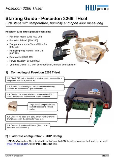
<strong>Poseidon</strong> <strong>3266</strong> <strong>THset</strong> package contains:<br />
• <strong>Poseidon</strong> model <strong>3266</strong> [600 252]<br />
• <strong>Poseidon</strong> T-Box2 [600 280]<br />
• Temperature probe Temp-1Wire 3m<br />
[600 005]<br />
• Humidity probe Humid-1Wire 3m<br />
[600 279]<br />
• Door contact [600 119]<br />
• Power adapter 12V [600 080]<br />
• „<strong>Starting</strong> <strong>Guide</strong>“, CD with documentation, manual and Software<br />
1) Connecting of <strong>Poseidon</strong> <strong>3266</strong> <strong>THset</strong><br />
1.1) Check DIP switch. Installation position has to be same like in<br />
the picture (DIP1=Off, DIP2=Off).<br />
1.2) Four inputs are designed for the contact connecting.<br />
Connect the door sensor – part of the start set.<br />
1.3) Connect the power adapter to power socket (230 /<br />
110V) and connect it to <strong>Poseidon</strong> power connector.<br />
1.4) Connect temperature and<br />
humidity sensors to T-Box2<br />
switch.<br />
1.5) Connect the cable of T-Box2 switch into SENSORS<br />
(RJ12) connector, the connector must click.<br />
1.6) Connect <strong>Poseidon</strong> to Ethernet (direct cable<br />
to Switch, crossed to PC)<br />
2) IP address configuration - UDP Config<br />
UDP Config start-up file is located in root of supplied CD; latest version can be found on our web:<br />
www.<strong>HW</strong>-<strong>group</strong>.com, follow <strong>Poseidon</strong> <strong>3266</strong> link.<br />
www.<strong>HW</strong>-<strong>group</strong>.com 600 282
<strong>Poseidon</strong> <strong>3266</strong> <strong>THset</strong> – starting guide<br />
<strong>HW</strong> <strong>group</strong><br />
• Click the icon to run UDP Config<br />
program – it will automatically search<br />
for connected devices<br />
In case the device was not connected to<br />
network during UDP Config start-up, you<br />
can easily click the Find Devices button<br />
to repeat the search again.<br />
The Program will search for devices on<br />
your local network. The <strong>Poseidon</strong><br />
identifies them according to MAC<br />
address which is printed on label located<br />
on bottom part of each device.<br />
Double click on MAC address will open basic<br />
settings dialog window.<br />
In this moment it is neccesary to setup network parameters.<br />
Notice: In case you do not have following information, contact your<br />
network administrator<br />
• IP address<br />
• HTTP Port<br />
• Mask<br />
• Gateway IP address<br />
• Name of your device - optional<br />
Do not forget to click Apply Changes button to safe new values to<br />
<strong>Poseidon</strong> memory<br />
Note: to setup IP address you can use as optional:<br />
• Hercules (/Hercules.exe)<br />
• RS-232 serial port (any terminal, DIP1=ON, 9600 8N1)<br />
3) <strong>Poseidon</strong> configuration – Web browser<br />
3.1) Enter IP address of the device to your web browser address bar or run UDP Config and click<br />
to the IP address.<br />
www.<strong>HW</strong>-<strong>group</strong>.com 600 282
<strong>Poseidon</strong> <strong>3266</strong> <strong>THset</strong> – starting guide<br />
<strong>HW</strong> <strong>group</strong><br />
3.2) WWW page <strong>Poseidon</strong> <strong>3266</strong><br />
Device IP address<br />
Input number for<br />
connect the contact<br />
Input value while<br />
WWW is loaded<br />
Alarm definition for<br />
every input<br />
Unique sensor ID<br />
(serial number)<br />
Value out of safe<br />
range alert<br />
Device name<br />
Detailed „Flash<br />
setup“ configuration<br />
Description of SNMP<br />
MIB and values.XML<br />
structures<br />
Special configuration<br />
„Telnet setup“<br />
• Current Value – current value of connected sensor. „-999.9“ value means that the sensor is not<br />
available or is initializing after start.<br />
• Safe Range – Sensor´s value range out of Alarm.<br />
• Alarm Alert – defined for sensor, monitoring of safe range switched on and where alert of exceeding<br />
“Safe Range” and Alarm status are sent (inputs for contacts).<br />
• „For more information ..“ – Contact for service organization, you can change it from „Telnet setup“.<br />
3.3) Reading of current values<br />
• XML – values.xml file, format described using XSD – for download on the main page, detailed<br />
comments of XML structure are in the manual.<br />
• SNMP – describing file of poseidon.mib you can download from main page, Standard SNMP port 161<br />
and 162 can be configured in Flash setup.<br />
• Modbus/TCP– structure description is in the manual or in application examples. Standard port 502 is<br />
opened for reading.<br />
www.<strong>HW</strong>-<strong>group</strong>.com 600 282
<strong>Poseidon</strong> <strong>3266</strong> <strong>THset</strong> – starting guide<br />
4) Flash Setup configuration<br />
<strong>HW</strong> <strong>group</strong><br />
After the click „Flash Setup“ link from WWW page, the graphic configuration version in browser is<br />
opened. Macromedia Flash player in web browser must be installed. If you don´t have it, you can<br />
download his last version from Internet or find it on CD:<br />
\<strong>Poseidon</strong>\install_flash_player_7.msi<br />
Using Flash setup you can:<br />
• Setup names of sensors, „Safe Range“ for alarm and where Alarm<br />
alert will be sent.<br />
• Monitor current values, refresh in seconds.<br />
• Select temperature units (°C, °F, °K)<br />
• Setup actual time and NTP server for synchronize the time.<br />
• Setup SNMP parameters (Community names & rights) and define<br />
where to send SNMP Traps<br />
• Setup Alarm alert via email and test it.<br />
• Setup security elements: Names and password, ranges of IP<br />
addresses<br />
More information can be found in manual or on www.<strong>HW</strong>-<strong>group</strong>.com.<br />
www.<strong>HW</strong>-<strong>group</strong>.com 600 282