Operating manual VIBTRONIC Controller for magnetic vibrators
Operating manual VIBTRONIC Controller for magnetic vibrators
Operating manual VIBTRONIC Controller for magnetic vibrators

Create successful ePaper yourself
Turn your PDF publications into a flip-book with our unique Google optimized e-Paper software.
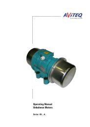
<strong>Operating</strong> <strong>manual</strong><br />
®<br />
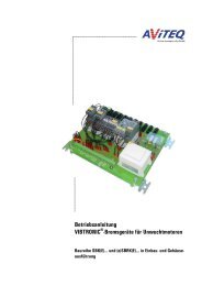
<strong>VIBTRONIC</strong> <strong>Controller</strong><br />
<strong>for</strong> <strong>magnetic</strong> <strong>vibrators</strong><br />
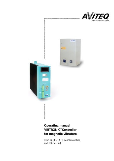
Type SD(E)...-1 in panel mounting<br />
and cabinet unit
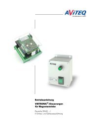
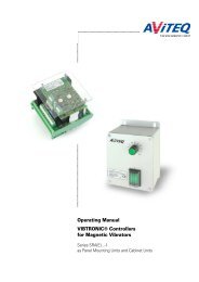
Connections,<br />
control and display elements<br />
Digital display (4 digits)<br />
Input keys<br />
Pin keys (e.g., <strong>for</strong> RESET)<br />
Type label<br />
Operation indicators (LEDs)<br />
Serial interface<br />
Connector <strong>for</strong> the external display<br />
or <strong>for</strong> the service module (options)<br />
Input/output connections (signal lines)<br />
Mains connection and<br />
<strong>magnetic</strong> vibrator connection<br />
on bottom side of unit
<strong>Operating</strong> Manual <strong>for</strong> <strong>Controller</strong> <strong>VIBTRONIC</strong> ® SD(E)…-1<br />
Intended Use<br />
The <strong>VIBTRONIC</strong> SD(E)…-1 type controllers are designed and constructed as alternating<br />
voltage regulators <strong>for</strong> controlling <strong>magnetic</strong> <strong>vibrators</strong>; they operate on the<br />
voltage regulation principle (phase regulation).<br />
The controllers have been designed <strong>for</strong> use with mains networks having a frequency<br />
of either 50 or 60 Hz and a sinusoidal voltage.<br />
Do not use the controllers in environments with explosion hazards (explosives,<br />
gassy environments)! Observe the in<strong>for</strong>mation regarding the intended uses given<br />
in Chapter 1.3!<br />
Modular Device Design<br />
The controllers of type <strong>VIBTRONIC</strong> SD(E)…-1 are modularly designed and available<br />
in a wide range of option variants. Some modules can be retrofitted.<br />
Observe any additional operating <strong>manual</strong>s which may have been provided <strong>for</strong> the<br />
modules!<br />
©2003 AViTEQ Vibrationstechnik GmbH Version 01/2003 0–2
For Your Safey<br />
You will find three different types of symbols in this operating <strong>manual</strong> which are<br />
intended to point out important in<strong>for</strong>mation:<br />
DANGER!<br />
The DANGER warning describes procedures or conditions which could have dangerous<br />
or even life-threatening consequences <strong>for</strong> the person installing or using the<br />
equipment.<br />
ATTENTION!<br />
NOTE<br />
You will find this in<strong>for</strong>mation with procedures in which a danger of damage to<br />
equipment exists. This damage could also result in injury to personnel (e.g., from a<br />
fire!)<br />
Notes provide in<strong>for</strong>mation about individual procedures. Notes explain circumstances,<br />
clarify terminology or provide tips <strong>for</strong> simplifying processes or procedures.<br />
0–3 ©1998 AViTEQ Vibrationstechnik GmbH Version 01/2003
<strong>Operating</strong> Manual <strong>for</strong> <strong>Controller</strong> <strong>VIBTRONIC</strong> ® SD(E)…-1<br />
Although we developed the <strong>VIBTRONIC</strong> controllers taking into account all safety<br />
measures, operational error cannot be completely eliminated. In the interest of<br />
your safety and that of your colleagues, observe the following in<strong>for</strong>mation:<br />
DANGER!<br />
When connected to mains, dangerously high voltages are present inside the controller.<br />
Touching electrically live components can be lethal! Be<strong>for</strong>e switching on<br />
mains power, ensure that no live parts can be touched.<br />
DANGER!<br />
Explosions can be life threatening and result in great damage to equipment. Do not<br />
use the controller in environments with explosion hazards. The controller of type<br />
SD(E)…-1 is not designed <strong>for</strong> environments with explosion hazards or firedamp<br />
environments and must not be used in such without first taking appropriate measures.<br />
ATTENTION!<br />
Unsuitable controllers, operation with the incorrect mains voltage/frequency could<br />
result in damage to the <strong>magnetic</strong> vibrator. Make sure that the connection values<br />
are correct and compare them with the device's type labels!<br />
ATTENTION!<br />
Make certain that the fuse protection <strong>for</strong> the controller is in accordance with the<br />
circuit diagram (Figure 4.16)! Install at least one fuse – but in any case, F1 in<br />
accordance with circuit diagram Figure 4.16 – as super-fast-acting safety fuse <strong>for</strong><br />
safeguarding the power semiconductor in the controller.<br />
ATTENTION!<br />
Destruction of the <strong>magnetic</strong> vibrator! If the <strong>magnetic</strong> vibrator is operated with an<br />
external vibration sensor (PA) and the operating mode "usable working stroke regulation"<br />
selected, the <strong>magnetic</strong> vibrator must always be calibrated in accordance<br />
with commissioning procedure – as described in Chapter 5.2.3 –. Direct selection<br />
of the <strong>magnetic</strong> vibrator from the type table, which is stored in the controller, can<br />
lead to collision mode and, there<strong>for</strong>e, result in destruction of the <strong>magnetic</strong> vibrator.<br />
NOTE<br />
With a reversing device, the vibrator voltage varies slightly on the horizontal drive<br />
with identical controller settings depending on the direction of conveyance. For<br />
this reason we recommend always calibrating the horizontal drive in accordance<br />
with commissioning procedure – as described in Chapter 5.2.3 . Direct selection of<br />
the horizontal drive from the type table, which is stored in the controller, may occasionally<br />
lead to slight collision mode and, there<strong>for</strong>e, result in destruction of the<br />
<strong>magnetic</strong> vibrator.<br />
©2003 AViTEQ Vibrationstechnik GmbH Version 01/2003 0–4
© 2003 AViTEQ Vibrationstechnik GmbH<br />
COPYRIGHT<br />
The SD(E)…-1 series <strong>VIBTRONIC</strong> controllers and this operating <strong>manual</strong> are protected by copyright. Any<br />
reengineering of the units will result in criminal prosecution. All rights to this operating <strong>manual</strong> are reserved,<br />
including reproduction via photo mechanical, print, data or any other possible medium, as well as in translation.<br />
Reproduction of this operating <strong>manual</strong>, complete or in part, requires the written consent of<br />
AViTEQ Vibrationstechnik GmbH.<br />
<strong>VIBTRONIC</strong> is a registered and protected trademark of AViTEQ Vibrationstechnik GmbH.<br />
This operating <strong>manual</strong> supports the intended use and appropriate deployment of <strong>VIBTRONIC</strong> controllers. For<br />
this purpose, the operating <strong>manual</strong> describes details that are significant <strong>for</strong> the product's operation. In particular,<br />
the operating <strong>manual</strong> provides no claim or guarantee of characteristics in the sense specified by<br />
§§ 434, 634 BGB (German civil code) or <strong>for</strong> the success of specific applications.<br />
AViTEQ Vibrationstechnik GmbH is liable <strong>for</strong> textual errors in the operating <strong>manual</strong> only where intent and<br />
gross negligence are demonstrated. In such cases, liability is limited to the effects the textual errors have on<br />
the product specified in the contract and other associated products produced by AViTEQ Vibrationstechnik<br />
GmbH as well as required products produced by AViTEQ Vibrationstechnik GmbH which are used in technical<br />
combination. This a<strong>for</strong>ementioned liability is limited to cases in which the value or functionality of the<br />
agreed upon characteristic of the product specified in the contract is vitiated or considerably diminished.<br />
This does not apply if liability <strong>for</strong> loss of life or limb or loss of health is mandatory.<br />
The textual errors, the damages as well as the justification and resulting causality underlying the liability<br />
claim are to be proven by the purchaser. In particular, AViTEQ Vibrationstechnik GmbH is not liable <strong>for</strong> damages<br />
or consequential damages resulting from the incorrect use of the operating <strong>manual</strong>. This does not apply<br />
to faulty content of the operating <strong>manual</strong>. This does not apply if liability <strong>for</strong> loss of life or limb or loss of<br />
health is mandatory. We are always grateful <strong>for</strong> suggestions and criticism!<br />
Unless otherwise stated, the relevant state of engineering is that at the time of the combined delivery of the<br />
product and the operating <strong>manual</strong> from AViTEQ Vibrationstechnik GmbH. The product is subject to technical<br />
changes without prior notice. Previous operating <strong>manual</strong>s are no longer valid.<br />
The General Conditions of Delivery Domestic and Abroad of AViTEQ Vibrationstechnik GmbH apply in their<br />
current version.<br />
Do you have questions? Or problems with installation and commissioning?<br />
Give us a call! We'll be glad to help you!<br />
AViTEQ Vibrationstechnik GmbH<br />
Im Gotthelf 16<br />
D 65795 Hattersheim-Eddersheim<br />
Telephone +49 (0) 61 45 / 503 - 0<br />
Fax +49 (0) 61 45 / 503 - 200<br />
Telefax Service-Hotline 0 61 45 / 503 - 112<br />
Hattersheim-Eddersheim (Germany), 29. January 2003<br />
0–5 ©1998 AViTEQ Vibrationstechnik GmbH Version 01/2003<br />
2002
<strong>Operating</strong> Manual <strong>for</strong> <strong>Controller</strong> <strong>VIBTRONIC</strong> ® SD(E)…-1<br />
Chapter Contents<br />
General remarks regarding this operating <strong>manual</strong>, our terms of<br />
business, warranty and areas of application of the controllers<br />
1<br />
Transport, storage, extent of delivery and disposal<br />
2<br />
Basics of the controller and its selection:<br />
the function description<br />
3<br />
Installation and electrical connection<br />
4<br />
To the point:<br />
Commissioning Step by Step<br />
5<br />
Prevention is better:<br />
Service and Maintenance<br />
6<br />
Not to be <strong>for</strong>gotten: Troubleshooting<br />
7<br />
Seek and find: the Index<br />
8<br />
©2003 AViTEQ Vibrationstechnik GmbH Version 01/2003 0–6
Table of Contents<br />
CONTENTS<br />
1 We are Partners. 1-1<br />
1.1 About this <strong>Operating</strong> Manual ..............................................................................................1-1<br />
1.2 Product Liability and Warranty ............................................................................................1-2<br />
1.3 Operative Range...................................................................................................................1-4<br />
1.4 Installation and <strong>Operating</strong> Personnel ..................................................................................1-5<br />
2 Transport, Delivery, Disposal 2-1<br />
2.1 Transport, Storage ...............................................................................................................2-1<br />
2.2 Extent of Delivery.................................................................................................................2-1<br />
2.3 Disposal ................................................................................................................................2-2<br />
2.3.1 Packing Materials .................................................................................................................2-2<br />
2.3.2 Returning the Device ...........................................................................................................2-2<br />
2.3.3 Materials Used in the Units..................................................................................................2-3<br />
3 Function Description 3-1<br />
3.1 Sizes......................................................................................................................................3-1<br />
3.2 Principles of Operation and Oscillation Rates.....................................................................3-1<br />
3.3 Scope of Operation..............................................................................................................3-2<br />
3.3.1 Regulation Types .................................................................................................................3-2<br />
3.3.2 Command Value Preset .......................................................................................................3-2<br />
3.3.3 External Release...................................................................................................................3-2<br />
3.3.4 <strong>Operating</strong> Messages ............................................................................................................3-3<br />
3.4 Models ..................................................................................................................................3-3<br />
3.4.1 Type Designation .................................................................................................................3-4<br />
4 Installation 4-1<br />
4.1 Mechanical Installation ........................................................................................................4-1<br />
4.1.1 Panel Mounting Unit ............................................................................................................4-1<br />
4.1.2 Cabinet Unit..........................................................................................................................4-2<br />
4.2 Terminal Assignments .........................................................................................................4-4<br />
4.2.1 Minimum Terminal Assignment..........................................................................................4-4<br />
4.2.2 Vibration Sensor (PAL) and Temperature Switch ..............................................................4-5<br />
4.2.3 Vibration Sensor (PA) ..........................................................................................................4-6<br />
4.2.4 Multiple Drives and Reversing Drive...................................................................................4-7<br />
4.2.5 Coarse and Fine Fill Rates....................................................................................................4-9<br />
4.2.6 Operational Transmitting Relay...........................................................................................4-9<br />
4.2.7 Switching On/Off Externally ..............................................................................................4-10<br />
4.2.8 External Control Input .......................................................................................................4-12<br />
4.2.9 Actual-value output............................................................................................................4-13<br />
4.2.10Supply-Voltage Output ......................................................................................................4-14<br />
4.3 Electrical Connection .........................................................................................................4-15<br />
4.3.1 Notes on electrical connection ..........................................................................................4-15<br />
4.3.2 Connection Diagram ..........................................................................................................4-17<br />
4.3.3 Vibration-Width Adjuster, Rotary-Type Knob and Scale..................................................4-17<br />
4.3.4 Switching on the <strong>Controller</strong>...............................................................................................4-19<br />
4.4 Other Connections .............................................................................................................4-19<br />
4.5 Electro<strong>magnetic</strong> Compatibility (EMC) ...............................................................................4-20<br />
i ©1998 AViTEQ Vibrationstechnik GmbH Version 01/2003
<strong>Operating</strong> Manual <strong>for</strong> controller <strong>VIBTRONIC</strong> ® SD(E)…-1<br />
5 Commissioning 5-1<br />
5.1 Fundamentals.......................................................................................................................5-1<br />
5.2 Commissioning ....................................................................................................................5-3<br />
5.2.1 Matching to the Vibration Conveyor Device.......................................................................5-3<br />
5.2.2 Setting the <strong>Operating</strong> Settings ............................................................................................5-6<br />
5.2.3 Matching to the Vibration Conveyor Devices Produced by Other Manufacturers ...........5-8<br />
5.2.4 Multiple Drive and Reversing Drive...................................................................................5-10<br />
5.2.5 Resetting to Factory Base Settings ...................................................................................5-11<br />
5.3 Input Codes <strong>for</strong> AViTEQ Magnetic Drives.........................................................................5-12<br />
5.4 <strong>Operating</strong> Displays.............................................................................................................5-14<br />
5.4.1 Continuous Display During Running Operation ...............................................................5-14<br />
5.4.2 Calling up the <strong>Operating</strong> and Set Values ..........................................................................5-14<br />
5.5 Form <strong>for</strong> Set Values ...........................................................................................................5-16<br />
6 Maintenance 6-1<br />
6.1 Check <strong>for</strong> Soiling ..................................................................................................................6-1<br />
6.2 Memory Battery ...................................................................................................................6-2<br />
7 Troubleshooting 7-1<br />
7.1 Repairs..................................................................................................................................7-1<br />
7.2 Fault Causes and Remedies.................................................................................................7-1<br />
8 INDEX 8-i<br />
©2003 AViTEQ Vibrationstechnik GmbH Version 01/2003 ii
We are Partners. – About this <strong>Operating</strong> Manual<br />
1 We are Partners.<br />
1.1 About this <strong>Operating</strong> Manual<br />
For whom?<br />
This operating <strong>manual</strong> is intended <strong>for</strong> the<br />
• installation technician who installs and commissions the <strong>magnetic</strong> vibrator.<br />
• electrician or engineer who carries out the installation of the controller, the<br />
electrical connection to the mains network and the connection to the <strong>magnetic</strong><br />
vibrator.<br />
All work on the controller must be carried out by qualified personnel (electricians<br />
or persons trained in electrical engineering according to IEC 364 and<br />
DINEN60204-1).<br />
Additional publications<br />
Supplements to this operating <strong>manual</strong>:<br />
• Connection diagram and dimension sheet <strong>for</strong> the controller<br />
• <strong>Operating</strong> <strong>manual</strong> <strong>for</strong> display and input module (separate short instructions as<br />
excerpt of this operating <strong>manual</strong>)<br />
• <strong>Operating</strong> <strong>manual</strong> <strong>for</strong> the service module<br />
Definitions<br />
• Magnetic vibrator: electro<strong>magnetic</strong>-mechanical unit <strong>for</strong> operating a vibration<br />
conveyor device<br />
• Vibration conveyor device: unit consisting of the <strong>magnetic</strong> vibrator and working<br />
unit (trough, tube, screen etc.)<br />
• <strong>Controller</strong>: the separately delivered electronic control unit assigned to the<br />
<strong>magnetic</strong> vibrator <strong>for</strong> connecting to the mains network<br />
• Cabinet unit: <strong>Controller</strong> in compact housing <strong>for</strong> wall or frame mounting (type<br />
SD…-1)<br />
• Panel mounting unit: <strong>Controller</strong> <strong>for</strong> installation in the switching cabinet or in<br />
an enclosed control location (type SDE…-1)<br />
NOTE<br />
This operating <strong>manual</strong> applies to the panel mounting unit. Variations specific to the<br />
cabinet unit are indicated at the appropriate points.<br />
1–1 ©1998 AViTEQ Vibrationstechnik GmbH Version 01/2003
<strong>Operating</strong> Manual <strong>for</strong> <strong>Controller</strong> <strong>VIBTRONIC</strong> ® SD(E)…-1<br />
Special symbols in this operating <strong>manual</strong><br />
Date of revision<br />
On the bottom in the righthand-side<br />
pages of this operating<br />
<strong>manual</strong>, the version<br />
number tells you the date<br />
when the page was last<br />
updated.<br />
Earlier in this <strong>manual</strong>, you should have learned how we indicate safety notices. If<br />
you have any questions about safe work practices regarding controllers and their<br />
environment, you should give us a call! We do not want you to endanger yourself<br />
or others just because the possible dangers were not clear to you!<br />
For your convenience and orientation, we use the following special indicators in<br />
this operating <strong>manual</strong>:<br />
• A round dot indicates a listing of characteristics and conditions.<br />
Upward pointing thumbs indicate that you should check something.<br />
The pointing finger indicates steps that you have to carry out.<br />
1<br />
1.2 Product Liability and Warranty<br />
The controllers correspond to the current State of Engineering and have been<br />
tested <strong>for</strong> each of its guaranteed functions prior to delivery. AViTEQ<br />
Vibrationstechnik GmbH carries out product and market research to aid further<br />
development and continuous improvement. Should malfunctions or failures occur<br />
despite these preventive measures, please contact our service department! We<br />
guarantee that appropriate measures <strong>for</strong> the repair of the defect will be taken<br />
immediately.<br />
The General Conditions of<br />
Delivery Domestic and Abroad<br />
of AViTEQ Vibrationstechnik<br />
GmbH apply in their current<br />
version.<br />
Conditions of warranty<br />
We guarantee that the product is free of defects within the scope of the technical<br />
product specifications published by AViTEQ Vibrationstechnik GmbH as well as<br />
technical specifications provided in this operating <strong>manual</strong>. No declarations of<br />
other product features or claims regarding additional characteristics are provided.<br />
AViTEQ Vibrationstechnik GmbH is not liable <strong>for</strong> the economic efficiency of the<br />
product or proper functionality when used <strong>for</strong> applications other than the purpose<br />
defined <strong>for</strong> the product as specified on the first, right-hand inner page in the front<br />
of this operating <strong>manual</strong>.<br />
Warranty exclusions<br />
Customers and third parties must consult with AViTEQ Vibrationstechnik GmbH<br />
and obtain our prior written consent be<strong>for</strong>e undertaking work inside or otherwise<br />
interfering with the product subject to the contract. Otherwise, liability <strong>for</strong><br />
devices, persons and other consequential damages of any type to the product<br />
specified in the contract and other legal assets is precluded, provided AViTEQ<br />
Vibrationstechnik GmbH is not co-responsible. Entering into or interfering with the<br />
equipment also renders any warranty null and void.<br />
AViTEQ Vibrationstechnik GmbH does not accept liability beyond the warranty<br />
entitlements stated in our terms of business on which the contract is based. This<br />
applies in particular to claims arising from loss of profit or other damage to purchaser/customer<br />
assets. This liability limitation does not apply unless the damage<br />
©2003 AViTEQ Vibrationstechnik GmbH Version 01/2003 1–2
We are Partners. – Product Liability and Warranty<br />
was intentional or caused through gross negligence and unless liability <strong>for</strong> loss of<br />
life or limb or loss of health is mandatory. This also does not apply when the purchaser/customer<br />
makes a claim <strong>for</strong> damages based on an incorrect claim of a<br />
characteristic or an agreed-upon characteristic. In the event of culpable violation<br />
of principle contractual obligations, AViTEQ Vibrationstechnik GmbH is also liable<br />
<strong>for</strong> criminal intent and gross negligence on the part of non-managing employees<br />
and <strong>for</strong> mild negligence. In the latter case, this is limited to the contract-typical,<br />
judicious, predicable damages.<br />
Warranty is excluded in particular when the units are used in environments, <strong>for</strong><br />
purposes, or connected to power supplies or to control systems that are not suitable<br />
<strong>for</strong> the controllers or that do not represent the common state of technology. In<br />
particular, no guarantee is provided <strong>for</strong> damages caused by unsuitable or incorrect<br />
use, incorrect mounting or commissioning by the purchaser/customer or third<br />
parties, natural wear, faulty or careless handling or unsuitable operating materials.<br />
The same applies <strong>for</strong> replacement parts, chemical, electrochemical or electrical<br />
influences provided they cannot be attributed to AViTEQ Vibrationstechnik GmbH<br />
and it's employees. Claims made <strong>for</strong> damages to objects other than that which is<br />
specified in the contract, so-called deficiency losses, are limited. In this case,<br />
AViTEQ Vibrationstechnik GmbH is liable, regardless of the legal basis, only in the<br />
cases of intent, gross negligence on the part of the owner/of its management or<br />
managing employee in the event of culpable loss of life or limb or health, in the<br />
event of deficiencies which are fraudulently concealed or the absence of which<br />
AViTEQ guaranteed, in the event of deficiencies of the delivered object, provided<br />
liability is provided in accordance with the product liability law <strong>for</strong> injury to persons<br />
and damages to materials or other special legal requirements.Also, we do<br />
not accept liability <strong>for</strong> damage to conveyor and automation plants caused by a<br />
malfunction of the product or by mistakes in the content of the operating <strong>manual</strong>.<br />
We do not accept liability <strong>for</strong> damage caused by accessories not supplied or certified<br />
by AViTEQ Vibrationstechnik GmbH. AViTEQ Vibrationstechnik GmbH is not<br />
responsible <strong>for</strong> the violation of patent rights or other rights of third parties outside<br />
the Federal Republic of Germany.<br />
We would like to point out that we are not liable <strong>for</strong> damage to the product subject<br />
to the contract, or <strong>for</strong> consequential damage to other property if the damage is<br />
caused by non-observation of safety regulations and/or warning notices.<br />
When entering the contract, the purchaser/customer is obliged to point out explicitly<br />
if the product is intended <strong>for</strong> private use and will be used by the purchaser/customer<br />
predominantly <strong>for</strong> this purpose.<br />
The <strong>VIBTRONIC</strong> controllers described in this operating <strong>manual</strong> must not be operated<br />
without consultation and corresponding release by AViTEQ Vibrationstechnik<br />
GmbH in the United States of America and other countries where US American<br />
laws are applicable.<br />
1–3 ©1998 AViTEQ Vibrationstechnik GmbH Version 01/2003
<strong>Operating</strong> Manual <strong>for</strong> <strong>Controller</strong> <strong>VIBTRONIC</strong> ® SD(E)…-1<br />
1.3 Operative Range<br />
When operating the controller<br />
of type SD(E)…-1 with a<br />
<strong>magnetic</strong> vibrator produced<br />
by another manufacturer in<br />
connection with a vibration<br />
sensor, the exact operating<br />
behavior cannot be predicted.<br />
The <strong>VIBTRONIC</strong> type SD(E)…-1 controllers allow continuous adjustment of the<br />
working stroke on the <strong>magnetic</strong> vibrator and thereby of the conveyor rate from<br />
vibration conveyor devices.<br />
The controllers must be used together only with AVITEQ <strong>magnetic</strong> <strong>vibrators</strong> or<br />
equivalent <strong>magnetic</strong> <strong>vibrators</strong> produced by other manufacturers in accordance<br />
with their intended use. In<strong>for</strong>mation in the vibration conveyor device and the <strong>magnetic</strong><br />
vibrator operating <strong>manual</strong>s is also to be observed!<br />
The controllers can be operated with <strong>magnetic</strong> <strong>vibrators</strong> produced by other manufacturers<br />
as long as it can be ensured that<br />
• the vibrator current of the <strong>magnetic</strong> vibrator lies in the range from 25 to<br />
100 % of the current <strong>for</strong> which the controller is designed,<br />
• the natural frequency of the <strong>magnetic</strong> vibrator lies in the range from 10 to<br />
20 % above the vibration frequency of the <strong>magnetic</strong> vibrator in later operation,<br />
• the controller and the <strong>magnetic</strong> vibrator are designed <strong>for</strong> the available mains<br />
voltage and mains frequency as specified by the type label,<br />
• the operating mode "voltage regulation" is selected.<br />
The <strong>magnetic</strong> vibrator current must never exceed the current <strong>for</strong> which the controller<br />
is designed as specified by the type label. If in doubt, contact us! The commissioning<br />
steps are described in Chapter 5.2.<br />
1<br />
Never use in the following cases:<br />
• Do not use <strong>for</strong> operation in environments subject to explosion risk or firedamp<br />
(explosives, (pit-) gas, risk of dust explosion)! The units are not explosionsafe!<br />
• Do not use at ambient temperatures below -25 and over +40 °C (cabinet<br />
unit) and +50 °C (panel mounting unit), or in tropical climates or areas where<br />
dew or condensation could <strong>for</strong>m! The units are designed <strong>for</strong> operation in moderate<br />
climatic environments!<br />
• Do not use together with <strong>magnetic</strong> <strong>vibrators</strong> which are not compatible with<br />
the controllers!<br />
• Do not use mains networks and mains frequencies other than those <strong>for</strong> which<br />
the controllers were designed!<br />
• Do not use at altitudes exceeding 1,000 m above sea level! The controller is<br />
not designed <strong>for</strong> high altitudes. Please contact us in special cases such as<br />
this!<br />
Connecting to mains and <strong>magnetic</strong> drives<br />
Only AVITEQ controllers connected to a sinusoidal mains network may be used <strong>for</strong><br />
operating the AVITEQ <strong>magnetic</strong> drives. For each AVITEQ <strong>magnetic</strong> drive model<br />
there is a corresponding controller.<br />
Other control and connection options are not included.<br />
©2003 AViTEQ Vibrationstechnik GmbH Version 01/2003 1–4
We are Partners. – Installation and <strong>Operating</strong> Personnel<br />
ATTENTION!<br />
If a <strong>magnetic</strong> vibrator is directly connected to mains or an inappropriate controller<br />
is used, the <strong>magnetic</strong> vibrator may be destroyed. Only use the appropriate controller!<br />
1.4 Installation and <strong>Operating</strong> Personnel<br />
Prior to installation and/or<br />
commissioning, you should<br />
familiarise yourself with all<br />
details of the controller and<br />
with the connection options<br />
of the <strong>magnetic</strong> vibrator. For<br />
more in<strong>for</strong>mation, see the<br />
chapter in the operating <strong>manual</strong><br />
on connecting the <strong>magnetic</strong><br />
<strong>vibrators</strong>.<br />
Persons involved with installation, commissioning, assembly, disassembly, adjustment<br />
or maintenance must have read and understood this operating <strong>manual</strong> in its<br />
entirety; in particular the safety notes. If you have any questions, we would be<br />
glad to help you!<br />
All work on the controller must be carried out by qualified personnel (electricians<br />
or persons trained in electrical engineering according to IEC 364 and<br />
DINEN60204-1).<br />
The controllers may only be serviced by personnel trained and authorized by<br />
AViTEQ Vibrationstechnik GmbH, Hattersheim-Eddersheim.<br />
AViTEQ Vibrationstechnik GmbH, Hattersheim-Eddersheim, is not liable <strong>for</strong> injuries<br />
or damage to property if this is not observed.<br />
This does not apply if liability <strong>for</strong> loss of life or limb or loss of health is mandatory.<br />
1–5 ©1998 AViTEQ Vibrationstechnik GmbH Version 01/2003
<strong>Operating</strong> Manual <strong>for</strong> <strong>Controller</strong> <strong>VIBTRONIC</strong> ® SD(E)…-1<br />
2 Transport, Delivery, Disposal<br />
2.1 Transport, Storage<br />
• Delivery: we ship controllers and accessories in purpose-built packaging to<br />
ensure that they reach their destination without damage.<br />
NOTE<br />
If the packing is visibly damaged in a way that indicates damage to the contents,<br />
contact the <strong>for</strong>warding agent! In further proceedings, take notice of the General<br />
Conditions of Business of the <strong>for</strong>warding agent in order not to risk your claim <strong>for</strong><br />
damages by improperly filled out <strong>for</strong>ms!<br />
<br />
Storage: unless special agreements concerning packing and storage have<br />
been made, the units, either packed or unpacked, must be stored and transported<br />
under "normal" conditions. This means in enclosed rooms with temperatures<br />
between -25 and +65 °C, relative humidity not to exceed 80 % (no<br />
dew or condensation), and no mechanical shocks or vibrations.<br />
2<br />
ATTENTION!<br />
Transporting and storing the units under inappropriate conditions may cause permanent<br />
damage. Such damage may not be detectable from the outside. AViTEQ<br />
Vibrationstechnik GmbH does not cover this case in its warranty and is not liable<br />
<strong>for</strong> any consequential damage.<br />
2.2 Extent of Delivery<br />
<br />
<br />
After unpacking, compare all parts against the bill of delivery and accompanying<br />
documents to ensure that all have arrived and are free of damage. This<br />
includes the controller in the installation or enclosed model itself, the circuit<br />
diagram packed together with the controller and, with installation models,<br />
separate potentiometer with rotary-type knob and scale <strong>for</strong> setting the working<br />
stroke.<br />
Compare the data on the <strong>magnetic</strong> vibrator and controller type labels with the<br />
delivery invoice and order documents!<br />
©2003 AViTEQ Vibrationstechnik GmbH Version 01/2003 2–1
Transport, Delivery, Disposal – Disposal<br />
<br />
Check to see that the <strong>magnetic</strong> vibrator and controller match by referring to<br />
Chapter 5.3 of this operating <strong>manual</strong>! Be<strong>for</strong>e using <strong>magnetic</strong> <strong>vibrators</strong> produced<br />
by other manufacturers, you must first make certain that the specifications<br />
are suitable <strong>for</strong> operation with the <strong>VIBTRONIC</strong> controller (see Chapter<br />
5.2.3)! If in doubt, contact us! We'll be glad to help you!<br />
ATTENTION!<br />
Unauthorised combinations may result in destruction of the <strong>magnetic</strong> vibrator or<br />
controller! Mains voltage, mains frequency and vibration frequency must be identical!<br />
The nominal current of the controller must be the same or greater than the<br />
peak current of the <strong>magnetic</strong> vibrator. Only connect compatible devices!<br />
2.3 Disposal<br />
2.3.1 Packing Materials<br />
The following materials are used by us <strong>for</strong> the shipping of controllers, depending<br />
on the mode of transport:<br />
• Polyethylene foil (PE) <strong>for</strong> device protection<br />
• Corrugated cardboard <strong>for</strong> outer and inner packing<br />
• Wooden cases <strong>for</strong> outer packing<br />
• Paper shavings <strong>for</strong> filler material<br />
• Styrofoam (Flo-Pack) <strong>for</strong> filler and damping material.<br />
All packing materials should be disposed of in accordance with local regulations of<br />
the delivery destination.<br />
Cardboard containers and paper packing tapes can be recycled within the RESY<br />
Disposal and Re-utilisation System. Where used, packaging foil, packing tapes,<br />
and foam foils are made from polyethylene (PE), the CFC-free cushions are usually<br />
made from polystyrene foam (PS). These packing materials consist of pure hydrocarbons<br />
and can thus be recycled.<br />
In special cases, we use steel packing bands and wooden cases free of chemical<br />
treatment.<br />
2.3.2 Returning the Device<br />
AViTEQ Vibrationstechnik GmbH takes back without charge controllers of type<br />
SD(E)…-1 delivered in 1998 or later when delivered shipping paid to AViTEQ<br />
Vibrationstechnik GmbH, Hattersheim-Eddersheim.<br />
2–2 ©1998 AViTEQ Vibrationstechnik GmbH Version 01/2003
<strong>Operating</strong> Manual <strong>for</strong> <strong>Controller</strong> <strong>VIBTRONIC</strong> ® SD(E)…-1<br />
2.3.3 Materials Used in the Units<br />
In case of disposal by the customer, and when exchanging components, the current<br />
local waste and disposal regulations apply and should be observed. We<br />
accept no responsibility <strong>for</strong> improperly disposed of parts and components!<br />
• For the disposal of the controller, the regulations <strong>for</strong> the disposal of electronic<br />
parts and components apply.<br />
• The power semiconductors used (thyristor and diode module) do not contain<br />
beryllium.<br />
• The lithium battery contained within the unit is to be disposed of separately<br />
(see illustration).<br />
1 Remove sheet-metal screws on side and top<br />
3 Lift off per<strong>for</strong>ated sheet profile<br />
2<br />
2 Remove sheet-metal screws<br />
on bottom<br />
4 Pull lithium battery<br />
upwards<br />
Detailed in<strong>for</strong>mation concerning the used materials is available from us upon<br />
request. In case of doubt, take advantage of our disposal offer!<br />
NOTE<br />
©2003 AViTEQ Vibrationstechnik GmbH Version 01/2003 2–3
Function Description – Sizes<br />
3 Function Description<br />
3.1 Sizes<br />
AVITEQ <strong>magnetic</strong> <strong>vibrators</strong> must be operated with the appropriate <strong>VIBTRONIC</strong><br />
controllers. Depending on the application and the size of the <strong>magnetic</strong> vibrator,<br />
AViTEQ Vibrationstechnik GmbH delivers controllers of series SD(E)…-1 in sizes<br />
25 and 50 A, as either cabinet or panel mounting unit.<br />
3.2 Principles of Operation and Oscillation<br />
Rates<br />
Type SD(E)…-1 controllers are alternating voltage regulators and they operate on<br />
the voltage regulation principle (phase regulation).<br />
Oscillation rates are given in "min -1 " and the vibration frequency in "Hz".<br />
NOTE<br />
• <strong>Controller</strong>s <strong>for</strong> vibration conveyor devices with an oscillation rate of<br />
1,500 min -1 (25 Hz) at a mains frequency of 50 Hz and<br />
1,800 min -1 (30 Hz) at a mains frequency of 60 Hz<br />
trigger every fourth mains half-wave.<br />
• <strong>Controller</strong>s <strong>for</strong> vibration conveyor devices with an oscillation rate of<br />
2,000 min -1 (33 1/3 Hz) with a mains frequency of 50 Hz<br />
trigger every third mains half-wave.<br />
• <strong>Controller</strong>s <strong>for</strong> vibration conveyor devices with an oscillation rate of<br />
3,000 min -1 (50 Hz) at a mains frequency of 50 Hz and<br />
3,600 min -1 (60 Hz) at a mains frequency of 60 Hz<br />
trigger every second mains half-wave.<br />
NOTE<br />
This new generation of controllers was designed with the EMC directive<br />
(89/336/EWG) in mind and meets the requirements of EN 50081-2 and<br />
EN 50082-2.<br />
3–1 ©1998 AViTEQ Vibrationstechnik GmbH Version 01/2003
<strong>Operating</strong> Manual <strong>for</strong> <strong>Controller</strong> <strong>VIBTRONIC</strong> ® SD(E)…-1<br />
3.3 Scope of Operation<br />
3.3.1 Regulation Types<br />
The <strong>VIBTRONIC</strong> <strong>Controller</strong>s of type SD(E)…-1 are designed <strong>for</strong> the following regulation<br />
types:<br />
• Voltage regulation without feedback from a sensor on the vibration conveyor<br />
device or in the <strong>magnetic</strong> vibrator<br />
• Limit regulation with collision protection by means of an external sensor in<br />
the <strong>magnetic</strong> vibrator (AViTEQ drive)<br />
• Usable working stroke regulation by means of a sensor on the vibration conveyor<br />
device<br />
Temperature monitoring of the <strong>magnetic</strong> vibrator is also possible – depending on<br />
the <strong>magnetic</strong> vibrator type.<br />
In normal operation, the controllers function without the sensor module (option)<br />
only as a voltage regulator. Terminals 13 and 14 must then, provided no AViTEQ<br />
<strong>magnetic</strong> vibrator with temperature monitor is connected, be connected by a<br />
bridge. Otherwise, the fault message: "F13" will be shown.<br />
The operation of an AViTEQ <strong>magnetic</strong> vibrator with vibration sensor (PAL) is permissible<br />
in the operating mode "limit regulation" only when the controller is<br />
equipped with a sensor module (option). This is indicated by a sticker on the front<br />
side of the controller similar to that depicted in the adjacent figure.<br />
3<br />
3.3.2 Command Value Preset<br />
The command value <strong>for</strong> the working stroke can optionally be preset by means of<br />
• a vibration-width adjuster (potentiometer) or<br />
• an external control input (0 … 10 V, 4 … 20 mA or 0 … 20 mA)<br />
The working stroke changes proportionally with the command value, i.e.: the<br />
larger the command value, the larger the working stroke.<br />
NOTE<br />
3.3.3 External Release<br />
The controller can be switched by the electronic release and, there<strong>for</strong>e, activated<br />
by means of, <strong>for</strong> example, a PLC (programmable logic controller). This external<br />
release can be made by means of<br />
• a potential free normally closed contact, or<br />
• two buttons or<br />
• an optical coupler.<br />
©2003 AViTEQ Vibrationstechnik GmbH Version 01/2003 3–2
Function Description – Models<br />
If an external release is not planned, the appropriate terminals are short-circuited<br />
with a plug-in bridge.<br />
The terminal assignments <strong>for</strong> the individual connection options are explained in<br />
Chapter 4.2.<br />
NOTE<br />
3.3.4 <strong>Operating</strong> Messages<br />
For displaying operating states, the units with unit no. G01 … are provided with<br />
one operating message relay and the units with unit no. G02 … are provided with<br />
two operating message relays. Independent of the device no., two operating LEDs<br />
are located on the front panel.<br />
The operating condition displays are explained in table 3.1.<br />
Green LED: OPERATION continuously illuminated mains voltage is present.<br />
Red LED: ERROR continuously illuminated <strong>Controller</strong> detects a fault and displays Fxx in the display!<br />
Check <strong>for</strong> possible causes according to the fault list in Chapter 7!<br />
Red LED: ERROR flashing <strong>Controller</strong> was not matched to the <strong>magnetic</strong> vibrator.<br />
The necessary work steps are described in Chapter 5.2.1 .<br />
Table 3.1<br />
Status of the LEDs upon switching on the controller<br />
In addition, the following in<strong>for</strong>mation is output by the display (<strong>for</strong> further details,<br />
refer to Chapter 5.4):<br />
• Working stroke (0-100%)<br />
• Natural frequency in combination with the sensor module (<strong>magnetic</strong> vibrator<br />
with PAL or vibration conveyor device with PA with unloaded vibration conveyor<br />
device)<br />
• Configuration data<br />
• Fault messages<br />
3.4 Models<br />
The controllers are deliverable in sizes 25 and 50 Ampère in the following models:<br />
• Cabinet unit SD…(IP54): enclosed compact housing <strong>for</strong> securing to walls or<br />
frames. Vibration-width adjuster and mains switch are installed on the front<br />
side of the housing.<br />
• Panel mounting unit SDE…(IP20): controller <strong>for</strong> installing in the switching<br />
cabinet or in closed control locations<br />
The corresponding technical data are located in table 3.2:<br />
3–3 ©1998 AViTEQ Vibrationstechnik GmbH Version 01/2003
<strong>Operating</strong> Manual <strong>for</strong> <strong>Controller</strong> <strong>VIBTRONIC</strong> ® SD(E)…-1<br />
Mains frequencies<br />
Vibration frequencies with 50 Hz mains<br />
Vibration frequencies with 60 Hz mains<br />
Nominal voltages with 50 Hz mains<br />
Nominal voltages with 60 Hz mains<br />
SD(E) 25/… SD(E) 50/…<br />
50 or 60 Hz<br />
25, 33 1/3 or 50 Hz<br />
30 or 60 Hz<br />
220 … 240 V<br />
380 … 420 V<br />
480 …520 V<br />
220 … 240 V<br />
380 … 420 V<br />
420 … 460 V<br />
480 … 520 V<br />
380 … 420 V<br />
480 … 520 V<br />
380 … 420 V<br />
420 … 460 V<br />
480 … 520 V<br />
Nominal current 25 A 50 A<br />
Maximum power loss in switching cabinet 75 W 85 W<br />
Table 3.2<br />
Technical data <strong>for</strong> type SD(E)…-1 controllers<br />
NOTE<br />
The permissible tolerances are, <strong>for</strong> the mains voltage, ± 10.0 % and, <strong>for</strong> the mains<br />
frequency, ± 0.5 %.<br />
3.4.1 Type Designation<br />
The controllers of type <strong>VIBTRONIC</strong> SD(E)…-1 are modularly designed and available<br />
in a wide range of option variants. Some modules can be retrofitted.<br />
The model of the delivered unit can be read from the type designation (see diagram<br />
below) on the type label on the front plate of the housing. Observe any additional<br />
operating <strong>manual</strong>s which may have been provided <strong>for</strong> the modules!<br />
3<br />
SD(E) 25/01-1<br />
Version number<br />
Encoding of the voltage range according to the table:<br />
Code Mains voltage range<br />
01 220 - 240 V<br />
02 380 - 420 V<br />
03 420 - 460 V<br />
(…<strong>for</strong> 60 Hz mains: 440 V)<br />
04 480 - 520 V<br />
Size (max. permissible output current)<br />
Installation model, without "E": cabinet unit<br />
Regulation device type: digital<br />
©2003 AViTEQ Vibrationstechnik GmbH Version 01/2003 3–4
Installation – Mechanical Installation<br />
4 Installation<br />
4.1 Mechanical Installation<br />
The installation steps <strong>for</strong> the two versions are described in the following sections:<br />
• Panel mounting unit, in Chapter 4.1.1 and<br />
• Cabinet unit, in Chapter 4.1.2<br />
4.1.1 Panel Mounting Unit<br />
The controllers are available as panel mounting units (IP 20 in accordance with<br />
EN 60529) <strong>for</strong> vertical installation in switching cabinets or control cases. They<br />
consist of:<br />
• the controller in the respective configuration,<br />
• the potentiometer with rotary-type knob and scale (delivered loose) and<br />
• the documentation (connection diagram, operating <strong>manual</strong> etc.).<br />
DANGER!<br />
Prior to installation: be<strong>for</strong>e opening the switching cabinet or control case, switch<br />
off the current supply, check that no voltages are present, and protect against<br />
unintentional reconnection!<br />
<br />
<br />
<br />
Use the hole pattern to orient yourself, see Figure 4.1 on the following page.<br />
Fasten the unit to a vibration-free vertical support wall or installation plate in<br />
the closeable switching cabinet (control location); hand-tighten the screws<br />
and use only the intended holes.<br />
If several controllers are to be installed adjacent to one another, a minimum<br />
installation clearance of 50 mm is to be maintained on the sides and 120 mm<br />
below (see Figure 4.1).<br />
NOTE<br />
The minimum lateral clearance between two controllers may be reduced from<br />
50 mm to 30 mm if it is ensured that the current consumption of both controllers is<br />
less than 30% of the nominal current (see controller type label) while in operation.<br />
Example: I
<strong>Operating</strong> Manual <strong>for</strong> <strong>Controller</strong> <strong>VIBTRONIC</strong> ® SD(E)…-1<br />
Minimum separation<br />
50<br />
7<br />
40<br />
10<br />
View X<br />
265<br />
285<br />
245<br />
20<br />
Neighboring unit<br />
Heat sink<br />
Minimum clearance<br />
120<br />
45<br />
80<br />
100<br />
7<br />
17.5<br />
26<br />
66<br />
250<br />
Neighboring unit<br />
Figure 4.1 Installation model: dimensions and hole pattern <strong>for</strong> securing to vertical<br />
vibration-free switching cabinet walls or installation plates<br />
Weight: 4.0 kg<br />
4<br />
ATTENTION!<br />
<strong>Controller</strong>s are temperature sensitive! Make certain that the units are not installed<br />
near external heat sources, such as direct sunshine or radiators. The ambient temperature<br />
must not exceed +50 °C during operation!<br />
4.1.2 Cabinet Unit<br />
The controllers are delivered in a closed housing (IP 54 acc. to EN 60529). The<br />
cabinet unit is suitable <strong>for</strong> mounting to vertical walls or frames.<br />
NOTE<br />
AViTEQ delivers the contollers in various housing models, depending on customer<br />
requirements. The customer can, thus, select from various housings with different<br />
dimensions depending on the available installation space.<br />
©2003 AViTEQ Vibrationstechnik GmbH Version 01/2003 4–2
Installation – Mechanical Installation<br />
An enclosed variant is shown below as an example.<br />
Mounting plate<br />
Figure 4.2<br />
Cabinet unit: dimensions and hole pattern <strong>for</strong> securing to vertical<br />
vibration-free walls or frames<br />
Weight of this model: approx. 25 kg<br />
Carry out the installation as follows:<br />
<br />
<br />
<br />
Screw the mounting plates (delivered loose) onto the housing as shown in<br />
Figure 4.2.<br />
Use the hole pattern on the included dimension sheet to orient yourself, and<br />
drill the necessary holes <strong>for</strong> the fastening screws.<br />
Hand-fasten the mounting plates to a vibration-free vertical wall or frame.<br />
<strong>Controller</strong>s are vibration sensitive! Do not install on vibrating components, and<br />
under no circumstances to the vibration conveyor device itself!<br />
ATTENTION!<br />
ATTENTION!<br />
<strong>Controller</strong>s are temperature sensitive! Make certain that the units are not installed<br />
near external heat sources, such as direct sunshine or radiators. The ambient temperature<br />
must not exceed +40 °C during operation!<br />
4–3 ©1998 AViTEQ Vibrationstechnik GmbH Version 01/2003
<strong>Operating</strong> Manual <strong>for</strong> <strong>Controller</strong> <strong>VIBTRONIC</strong> ® SD(E)…-1<br />
4.2 Terminal Assignments<br />
The following sections, Chapter 4.2.1 through Chapter 4.2.10 explain the terminal<br />
assignment on the controllers as well as the available options. Read these sections<br />
be<strong>for</strong>e you begin wiring, and observe the in<strong>for</strong>mation regarding electro<strong>magnetic</strong><br />
compatibility!<br />
4.2.1 Minimum Terminal Assignment<br />
The minimum terminal assignment <strong>for</strong> operating a <strong>magnetic</strong> vibrator <strong>for</strong> voltageregulated<br />
mode without external control input is shown in Figure 4.3. Terminals 13<br />
and 14 must be connected by a bridge.<br />
PE<br />
1 2 3 4 5 6 7 13 14<br />
21 22 23<br />
Bridge<br />
0<br />
PE L1 L2(N) Magnetic<br />
vibrator<br />
Mains switch<br />
Potentiometer<br />
1 kOhm (linear)<br />
Switch<br />
Normally closed contact<br />
4<br />
Figure 4.3 Standard terminal assignment with mains input (terminals PE, 1 and 2),<br />
<strong>magnetic</strong> vibrator (terminals 3 and 4) and vibration-width adjuster (terminals<br />
5, 6 and 7)<br />
ATTENTION!<br />
Make certain that the fuse protection <strong>for</strong> the controller is in accordance with connection<br />
diagram (see Figure 4.16). Install at least one fuse – but in any case, F1 in<br />
accordance with connection diagram Figure 4.16 – as a super-fast-acting safety<br />
fuse <strong>for</strong> safeguarding the thyristor in the controller.<br />
NOTE<br />
For <strong>magnetic</strong> <strong>vibrators</strong> without a vibration sensor and/or temperature switch, terminals<br />
13 and 14 must be connected by a bridge.<br />
If the bridge is missing, the fault message: "F13" is displayed, the red LED illuminates<br />
and the <strong>magnetic</strong> vibrator is switched off or does not start.<br />
©2003 AViTEQ Vibrationstechnik GmbH Version 01/2003 4–4
Installation – Terminal Assignments<br />
NOTE<br />
Use only potentiometers (limit values between 1 and 10 kOhm) with linear characteristics<br />
<strong>for</strong> the vibration-width adjuster. Shield the signal lines to guarantee electro<strong>magnetic</strong><br />
compatibility if the lines exceed five metres in length!<br />
Do not apply a potential to terminals 21, 22 or 23 as this may lead to damage of<br />
the controller!<br />
ATTENTION!<br />
NOTE<br />
To prevent switching faults, use only gold-plated or hermetically sealed contacts.<br />
Shield the signal lines to guarantee electro<strong>magnetic</strong> compatibility if the lines<br />
exceed five metres in length!<br />
4.2.2 Vibration Sensor (PAL) and Temperature Switch<br />
AViTEQ <strong>magnetic</strong> <strong>vibrators</strong>, series<br />
• MV_S… (with temperature switch) and<br />
• MV_S…P (with temperature switch and vibration sensor)<br />
are fitted at the factory with a flexible, 5-conductor connection cable.<br />
Remove the wire bridge from terminals 13 and 14.<br />
Connect the two black wires of the connection cable <strong>for</strong> the temperature<br />
switch and/or vibration sensor to terminals 13 and 14 (see Figure 4.4).<br />
NOTE<br />
The signal of the vibration sensor can only be analysed when the controller is<br />
equipped with the sensor module (option). The sensor module is a supplementary<br />
printed board which is installed ex works in the controller, although it can also be<br />
retrofitted.<br />
13 14<br />
ϑ<br />
Vibration sensor (PAL)<br />
Temperature switch<br />
Figure 4.4 Vibration sensor and temperature switch (terminals 13 and 14)<br />
4–5 ©1998 AViTEQ Vibrationstechnik GmbH Version 01/2003
<strong>Operating</strong> Manual <strong>for</strong> <strong>Controller</strong> <strong>VIBTRONIC</strong> ® SD(E)…-1<br />
ATTENTION!<br />
Destruction of the vibration sensor/temperature switch by connecting to the wrong<br />
terminals! Never connect the two black conductors of the connecting cable on the<br />
<strong>magnetic</strong> vibrator to terminals 1 and 2 or 3 and 4 of the controller!<br />
NOTE<br />
Electro<strong>magnetic</strong> compatibility: For line lengths longer than 50 m between <strong>magnetic</strong><br />
vibrator and controller: use a separate cable <strong>for</strong> the two black vibration sensor/temperature<br />
switch signal lines.<br />
If the line lengths are longer than 100 m, the two black signal lines must be<br />
shielded.<br />
4.2.3 Vibration Sensor (PA)<br />
Connect the vibration sensor as follows:<br />
Remove the wire bridge from terminals 13 and 14.<br />
<br />
Connect the two wires of the vibration sensor to terminals 13 and 14 (Figure<br />
4.5).<br />
NOTE<br />
The signal of the vibration sensor can only be analysed when the controller is<br />
equipped with the sensor module (option). The sensor module is a supplementary<br />
printed board which is installed ex works in the controller, although it can also be<br />
retrofitted.<br />
4<br />
13 14<br />
Vibration sensor (PA)<br />
Figure 4.5 Vibration sensor (terminals 13 and 14)<br />
NOTE<br />
Electro<strong>magnetic</strong> compatibility: if the line lengths are longer than 100 m, the two<br />
signal lines must be shielded.<br />
©2003 AViTEQ Vibrationstechnik GmbH Version 01/2003 4–6
Installation – Terminal Assignments<br />
ATTENTION!<br />
Destruction of the <strong>magnetic</strong> vibrator! If the <strong>magnetic</strong> vibrator is operated with an<br />
external vibration sensor (PA) and the operating mode "usable working stroke regulation"<br />
is selected, the <strong>magnetic</strong> vibrator must always be calibrated in accordance<br />
with the commissioning procedure – as described in Chapter 5.2.3. Direct<br />
selection of the <strong>magnetic</strong> vibrator from the type table, which is stored in the controller,<br />
can lead to collision mode and, there<strong>for</strong>e, result in destruction of the <strong>magnetic</strong><br />
vibrator.<br />
4.2.4 Multiple Drives and Reversing Drive<br />
For certain conveyor applications it is necessary to connect together two or more<br />
controllers. The connection technique is explained below using a typical example:<br />
reversing drive. Here, two controllers are connected to one another. The controllers<br />
control the horizontal and vertical drives on a reversing tube, respectively.<br />
Master/slave switching<br />
With this technique, the programming commands are used to define one controller<br />
as a slave device, the other as a master. The on/off switch of the slave device then<br />
functions as a direction reversing switch. The wiring of the two controllers is<br />
shown in Figure 4.6.<br />
On/Off<br />
Master<br />
Connect terminals of both units:<br />
09 (Ground)<br />
10 (Master/Slave)<br />
11 (Reversing mode)<br />
Slave<br />
Directional<br />
changeover<br />
switch<br />
0<br />
22<br />
23<br />
I<br />
21<br />
21<br />
22<br />
23<br />
0 I<br />
Terminals 3, 4<br />
Terminals 3, 4<br />
Reversing tube<br />
Vertical<br />
drives<br />
Horizontal drive<br />
Rectifier unit (NGE …)<br />
Figure 4.6<br />
Application example: reversing drive with two coupled SD(E)…-1<br />
4–7 ©1998 AViTEQ Vibrationstechnik GmbH Version 01/2003
<strong>Operating</strong> Manual <strong>for</strong> <strong>Controller</strong> <strong>VIBTRONIC</strong> ® SD(E)…-1<br />
ATTENTION!<br />
For a master/slave connection with and without reversing mode, the maximum<br />
permissible line length of the connection between terminals 9/10 and 11 is 2.5 m.<br />
In this case the lead must always be a shielded cable and the shielding connected<br />
to terminal 9 on the master.<br />
If an unshielded cable is used or line lengths greater than 2.5 m are used, the slave<br />
controller may be damaged.<br />
NOTE<br />
With a reversing unit, the vibrator voltage varies slightly on the horizontal drive<br />
with identical controller settings depending on the direction of conveyance. For<br />
this reason we recommend always calibrating horizontal drive in accordance with<br />
the commissioning procedure – as described in Chapter 5.2.3. Direct selection of<br />
the horizontal drive from the type table, which is stored in the controller, may occasionally<br />
lead to slight collision mode and, there<strong>for</strong>e, result in destruction of the<br />
<strong>magnetic</strong> vibrator.<br />
Special function with multiple drives at a vibration frequency of 33 Hz<br />
ATTENTION!<br />
NOTE<br />
With 33 Hz multiple drives and corresponding master/slave connection, pay particular<br />
attention to the mains connections of the controllers. Otherwise, a malfunction<br />
may occur, resulting in damage to the controllers. The correct mains connection is<br />
listed in the following Figure 4.7.<br />
Note special programming features (Chapter 5.2.4)!<br />
4<br />
Master (33 Hz)<br />
Slave (33 Hz)<br />
PE<br />
1 2 3 4<br />
PE<br />
1 2 3 4<br />
PE L1 L2 Magnetic<br />
vibrator<br />
Mains switch<br />
PE L2 L3 Magnetic<br />
vibrator<br />
Mains switch<br />
Figure 4.7<br />
Mains connection <strong>for</strong> 33 Hz multiple drives is connected as master/slave<br />
©2003 AViTEQ Vibrationstechnik GmbH Version 01/2003 4–8
Installation – Terminal Assignments<br />
4.2.5 Coarse and Fine Fill Rates<br />
When using the controller <strong>for</strong> dosing and filling processes, we recommend a circuit<br />
as shown in Figure 4.8 (other solutions are, of course, also possible!). In this<br />
circuit the two relays K1/K2 function as follows:<br />
• K2 initiates the filling process.<br />
• K1 switches at 95% full weight.<br />
• At 100% full weight, both relays return to their rest positions.<br />
5 6 7<br />
21 22 23<br />
K2<br />
Potentiometer<br />
(precision current)<br />
1 kOhm (linear)<br />
0<br />
0<br />
K1<br />
Relay K1<br />
(rest position)<br />
Relay K2 (rest position)<br />
Potentiometer (primary current)<br />
1 kOhm (linear)<br />
Figure 4.8 Coarse and fine fill rates switching (terminals 5, 6 and 7, or 21, 22, 23)<br />
NOTE<br />
To prevent switching faults, use only gold-plated or hermetically sealed contacts.<br />
Use only potentiometers (limit values between 1 and 10 kOhm) with linear characteristics<br />
<strong>for</strong> the vibration-width adjuster. Shield the signal lines to guarantee electro<strong>magnetic</strong><br />
compatibility if the lines exceed five metres in length!<br />
4.2.6 Operational Transmitting Relay<br />
The controller is equipped with two operational transmitting relays according to<br />
the following illustration:<br />
K1<br />
K2<br />
19 20<br />
24 25 26<br />
Figure 4.9<br />
Operational transmitting relays<br />
4–9 ©1998 AViTEQ Vibrationstechnik GmbH Version 01/2003
<strong>Operating</strong> Manual <strong>for</strong> <strong>Controller</strong> <strong>VIBTRONIC</strong> ® SD(E)…-1<br />
The following switching states can be analysed:<br />
Terminals<br />
19 and 20<br />
Terminals<br />
24 and 25<br />
Terminals<br />
25 and 26<br />
Case<br />
open closed open • Mains voltage (terminals 1 and 2) present.<br />
• The controller is ready <strong>for</strong> operation.<br />
• <strong>Controller</strong> switched off via signal lines (terminals 21, 22 and 23)<br />
and/or no appropriate command value is present.<br />
closed closed open • Mains voltage (terminals 1 and 2) present.<br />
• The controller is ready <strong>for</strong> operation.<br />
• <strong>Controller</strong> switched on via signal lines (terminals 21, 22 and 23)<br />
and an appropriate command value is present.<br />
open open closed • Mains voltage (terminals 1 and 2) not present, or<br />
• standstill of the <strong>magnetic</strong> vibrator due to a fault message (F …)<br />
Figure 4.10<br />
Switching states of the operational transmitting relays<br />
NOTE<br />
The operational transmitting relay on terminals 19 and 20 is present beginning<br />
with unit no. G02 00 … and opens when mains voltage is present and the corresponding<br />
ready signal is switched via the signal lines (terminals 21, 22 and 23)<br />
and a corresponding command value is present.<br />
As long as there is no line breakage between the controller and <strong>magnetic</strong> vibrator,<br />
it can be assumed that the <strong>magnetic</strong> vibrator is running. The operational transmitting<br />
relay cannot be used with 100% reliability to determine whether the vibration<br />
conveyor device is running. In order to do this, it requires a vibration sensor with<br />
appropriate signal analysis on the vibration conveyor device.<br />
4<br />
ATTENTION!<br />
The load rating of the individual operational transmitting relays is maximum<br />
30 V DC and maximum 2.0 A <strong>for</strong> direct current and maximum 125 V AC and maximum<br />
0.4 A <strong>for</strong> alternating current.Destruction of the operational transmitting relay<br />
and possibly of the controller! When dimensioning, note the permissible values<br />
given above <strong>for</strong> the load of the operational transmitting relay.<br />
4.2.7 Switching On/Off Externally<br />
The controller can be externally switched on or off by means of a switch (relay),<br />
button or optical coupler. The corresponding terminal assignments are shown in<br />
Figure 4.11.<br />
Requirements <strong>for</strong> the external switching element:<br />
• voltage-free contacts<br />
• precision contacts <strong>for</strong> 10 V DC<br />
• maximum load 5 mA<br />
©2003 AViTEQ Vibrationstechnik GmbH Version 01/2003 4–10
Installation – Terminal Assignments<br />
Do not apply voltage to terminals 21, 22 or 23 as this may result in damage to the<br />
controller!<br />
ATTENTION!<br />
NOTE<br />
To prevent switching faults, use only gold-plated or hermetically sealed contacts.<br />
Shield the signal lines to guarantee electro<strong>magnetic</strong> compatibility if the lines<br />
exceed five metres in length!<br />
Switching on/off externally<br />
21<br />
22 23<br />
Switch<br />
0 I<br />
21<br />
22 23<br />
Optical coupler<br />
Buttons<br />
0<br />
I<br />
max. 5 mA<br />
21 22 23<br />
Figure 4.11<br />
Switching on/off externally<br />
4–11 ©1998 AViTEQ Vibrationstechnik GmbH Version 01/2003
<strong>Operating</strong> Manual <strong>for</strong> <strong>Controller</strong> <strong>VIBTRONIC</strong> ® SD(E)…-1<br />
4.2.8 External Control Input<br />
External command value/potentiometer, switchable<br />
External command value<br />
5 6 7<br />
15 16 17 18<br />
5 6 7<br />
15 16 17 18<br />
External command value 0… 10 V<br />
0<br />
External<br />
Potentiometer<br />
1 kOhm (internal)<br />
_ +<br />
0 … 10 V external control input<br />
Internal<br />
_<br />
+<br />
0 … 10 V external control input<br />
External command value 4… 20 mA<br />
5 6 7<br />
0<br />
Potentiometer<br />
1 kOhm (internal)<br />
_<br />
+<br />
4…20mA<br />
external control input<br />
15 16 17 18 5 6 7 15 16 17 18<br />
Internal<br />
External<br />
_<br />
+<br />
4…20mA<br />
external control input<br />
4<br />
External command value 0… 20 mA<br />
5 6 7<br />
0<br />
15 16 17 18<br />
Potentiometer<br />
1 kOhm (internal)<br />
_<br />
+<br />
0…20mA<br />
external control input<br />
Internal<br />
External<br />
5 6 7<br />
15 16 17 18<br />
_<br />
+<br />
0…20mA<br />
external control input<br />
Figure 4.12<br />
Various options <strong>for</strong> external control input<br />
©2003 AViTEQ Vibrationstechnik GmbH Version 01/2003 4–12
Installation – Terminal Assignments<br />
The controllers may be operated with an external command value entry (external<br />
control input). The following external command values can be used <strong>for</strong> setting the<br />
working stroke:<br />
• 0…10VDC<br />
• 4…20mADC<br />
• 0…20mADC<br />
NOTE<br />
If necessary, you can switch between external control inputs by means of a switch<br />
or relay or between command value presettings by means of a vibration-width<br />
adjuster (potentiometer).<br />
Figure 4.12 shows the various options and terminal assignments <strong>for</strong> presetting<br />
external command values.<br />
The changeover between 0 … 20 mA and 4 … 20 mA takes place by means of<br />
software via program item P11_ – as described in table 5.3 in Chapter 5.2.2.<br />
NOTE<br />
To prevent switching faults, use only gold-plated or hermetically sealed contacts.<br />
NOTE<br />
Use only potentiometers (limit values between 1 and 10 kOhm) with linear characteristics<br />
<strong>for</strong> the vibration-width adjuster. Shield the signal lines to guarantee electro<strong>magnetic</strong><br />
compatibility if the lines exceed five metres in length!<br />
4.2.9 Actual-value output<br />
The controller is equipped with an actual-value output.<br />
8 9<br />
+ –<br />
Figure 4.13 Actual-value output (terminals 8 and 9)<br />
4–13 ©1998 AViTEQ Vibrationstechnik GmbH Version 01/2003
<strong>Operating</strong> Manual <strong>for</strong> <strong>Controller</strong> <strong>VIBTRONIC</strong> ® SD(E)…-1<br />
NOTE<br />
With the factory base setting, a maximum limit value of +10 V DC is output at terminal<br />
8. The initial value is set to 0 V.<br />
Program mode P1 (see table 5.3 in Chapter 5.2.2) can be used to set the maximum<br />
limit value to + 8 V DC and the initial value to + 2 V DC.<br />
Shield the signal lines to guarantee electro<strong>magnetic</strong> compatibility if the lines<br />
exceed two metres in length!<br />
NOTE<br />
Do not exceed the maximum load of the actual-value output of 5 mA. Loads in<br />
excess of this value may result in destruction of the controller.<br />
ATTENTION!<br />
4.2.10 Supply-Voltage Output<br />
<strong>Controller</strong>s with unit numbers starting with G02 00 … are equipped with a supplyvoltage<br />
output.<br />
9 10<br />
11 12<br />
4<br />
–<br />
+<br />
5 V DC (stabilised)<br />
Figure 4.14 Supply-voltage output (terminals 9 and 12)<br />
NOTE<br />
A stable voltage of + 5 ± 0.25 V DC is output at terminal 12.<br />
Shield the signal lines to guarantee electro<strong>magnetic</strong> compatibility if the lines<br />
exceed two metres in length!<br />
ATTENTION!<br />
Do not exceed the maximum load of the supply-voltage output of 100 mA. Loads in<br />
excess of this value may result in destruction of the corresponding fuse in the controller.<br />
©2003 AViTEQ Vibrationstechnik GmbH Version 01/2003 4–14
Installation – Electrical Connection<br />
4.3 Electrical Connection<br />
4.3.1 Notes on electrical connection<br />
DANGER!<br />
Avoid accidents - observe regulations! VDE regulations and guidelines of your<br />
power company apply to the connection of earth, neutral line, and protective circuitry!<br />
The connection must be carried out only by trained personnel (certified<br />
electrician or electrically trained person in accordance with IEC 364 and<br />
EN 60204-1).<br />
<br />
<br />
<br />
Switch off the current supply.<br />
Verify that no voltages are present!<br />
Protect against unintentional reconnection!<br />
Secondary circuit wiring in the load circuit<br />
The following wiring sequence must absolutely be observed:<br />
Switching on:<br />
Relay K2 of the enabling circuit should be connected either simultaneously with or<br />
following the power protection, but not preceding it.<br />
NOTE<br />
If the enabling circuit is connected in front of contactor K1, a fault message<br />
appears following a pickup delay of approx. 0.5 s (usually F12)! Independent of<br />
this, fault message "F12" must be suppressed under P14x (see table 5.3).<br />
Switching off:<br />
To switch off, you can select between two options:<br />
Varistor protection unit required<br />
No varistor protection unit necessary<br />
1 Contactor K1 and relay K2 open simultaneously.<br />
With this type of switching, a high transient voltage peak occurs on the<br />
solenoid due to the high inductance. This voltage peak cannot be dissipated<br />
by means of the damping elements in the controller. The peak poses a<br />
threat to the windings of the <strong>magnetic</strong> vibrator.<br />
To reduce the peak to a safe level <strong>for</strong> this type of connection, a varistor protection<br />
unit (type VSE-…, see Figure 4.15) must be permanently connected<br />
in parallel to the <strong>magnetic</strong> vibrator between the vibrator-side terminals.<br />
2 The contactor K1 opens after relay K2.<br />
The current in the <strong>magnetic</strong> vibrator has already fallen to zero by the time<br />
the contactor is opened; a varistor protection unit is not necessary.<br />
4–15 ©1998 AViTEQ Vibrationstechnik GmbH Version 01/2003
<strong>Operating</strong> Manual <strong>for</strong> <strong>Controller</strong> <strong>VIBTRONIC</strong> ® SD(E)…-1<br />
Gold contact<br />
4<br />
Magnetic vibrator<br />
Figure 4.15<br />
Wiring example <strong>for</strong> installation of a protection varistor<br />
Mains fuse<br />
For fuse protection of the thyristors in the controller, fuse F1 is to be installed in<br />
the mains lead L1 according to connection diagram (Figure 4.16) as a super-fastacting<br />
fuse. For fuse F2 in the mains lead L2 as per connection diagram (Figure<br />
4.16), we recommend a time-lag fuse.<br />
Fuses F1 and F2 are to be dimensioned according to the nominal current of<br />
the connected <strong>magnetic</strong> vibrator.<br />
ATTENTION!<br />
Make certain that fuse protection <strong>for</strong> the controller is in accordance with connection<br />
diagram (see Figure 4.16). Install at least one fuse – but in any case, F1 in<br />
accordance with circuit diagram Figure 4.16 – as a super-fast-acting safety fuse<br />
<strong>for</strong> safeguarding the thyristor in the controller.<br />
©2003 AViTEQ Vibrationstechnik GmbH Version 01/2003 4–16
Installation – Electrical Connection<br />
4.3.2 Connection Diagram<br />
Connection diagram <strong>for</strong> the controller see Figure 4.16 on the following page.<br />
The appropriate connection diagram is delivered with each controller. Note the<br />
minimum terminal assignment (see Figure 4.3).<br />
4.3.3 Vibration-Width Adjuster, Rotary-Type Knob and<br />
Scale<br />
A linear 1 kOhm potentiometer is always included in the delivery from the factory<br />
(see Figure 4.17). The technical data are listed in the following table 4.18.<br />
Figure 4.17<br />
Potentiometer, rotary-type knob, scale<br />
Component Type Data Weight Part number<br />
Potentiometer Megatron MUP 4000 1 kOhm linear<br />
Rotation angle: 300°<br />
35 g 2550<br />
Rotary-type knob 334.6/63/100 Plastic, black 26 g 1286<br />
Scale SE 2-021 Polished aluminium; dial graduation<br />
and numbers, black<br />
20 g 2745<br />
Table 4.18<br />
Vibration-width adjuster, technical data<br />
4–17 ©1998 AViTEQ Vibrationstechnik GmbH Version 01/2003
<strong>Operating</strong> Manual <strong>for</strong> <strong>Controller</strong> <strong>VIBTRONIC</strong> ® SD(E)…-1<br />
4<br />
see below<br />
Mains<br />
Size<br />
to be provided by the customer<br />
or:<br />
MV_33-1<br />
MV_S…-_P<br />
MV_S…_ (Example: MVES50-1)<br />
or:<br />
Command value<br />
Conf. mode<br />
Pot. 20 mA<br />
Working-stroke actual value<br />
H00.0<br />
Operation OFF/Error<br />
or:<br />
Figure 4.16<br />
Installation model connection diagram<br />
©2003 AViTEQ Vibrationstechnik GmbH Version 01/2003 4–18
Installation – Other Connections<br />
4.3.4 Switching on the <strong>Controller</strong><br />
When operating the controller, note that the built-in processor requires approximately<br />
2 seconds <strong>for</strong> internal control processes after controller is connected to<br />
mains. Only after this time lapse has passed is the external ouput (Axxx) shown in<br />
the display and are external control commands (e.g. from the service module)<br />
accepted.<br />
4.4 Other Connections<br />
To extend the control functions and to simplify operation, the controller can be fitted<br />
with additional modules.<br />
• Sensor module <strong>for</strong> analysing a vibration sensor (see also Chapter 4.2.2 Vibration<br />
Sensor (PAL) and Temperature Switch, or Chapter 4.2.3 Vibration Sensor<br />
(PA)): The sensor module can be installed ex works or retrofitted by the customer<br />
(see separate installation instructions <strong>for</strong> the sensor module).<br />
• External display module (accessory): This display module is connected in parallel<br />
to the display/input module in the controller and displays all in<strong>for</strong>mation<br />
which appears simultaneously on the built-in display in the controller. The<br />
external display, which in the standard version may have a lead wire up to<br />
2 m in length, is primarily <strong>for</strong> installation in the control cabinet <strong>for</strong> an enclosed<br />
model.<br />
The external display module is plugged into the provided d-sub socket (Display)<br />
on the front side of the controller with a standard plug (9-pole) and is<br />
immediately functional.<br />
• Service module (accessory): The service module makes it possible to set the<br />
controller externally, independent of the display and input modules built into<br />
the controller. It includes all functions which can also be executed with the<br />
display and input module of the controller. The operation and adjustment of<br />
the digital controller is simpler with the service module than with the display<br />
and input module. This is because all messages and input fields appear as<br />
self-explanatory plain texts in the LCD. Only with the service module is it possible<br />
<strong>for</strong> the user to call up and delete a list which contains the operating and<br />
fault messages with their associated times. Date and time can only be set via<br />
the service module. In addition, the service module can be used to read the<br />
software version of the controller.<br />
The service module is plugged into the labeled d-sub socket (see above) on<br />
the front panel of the controller with a standard plug and is immediately functional.<br />
The function and operation are described in a separate operating <strong>manual</strong>.<br />
• Serial interface RS232C/RS485 (option): This bi-directional interface can be<br />
used <strong>for</strong> both programming of the controller as well as <strong>for</strong> calling up operating<br />
and fault protocols from a higher-order PLC controller or via a laptop or PC.<br />
The serial interface can be installed ex works or retrofitted by the customer<br />
(see separate installation instructions and operating <strong>manual</strong>).<br />
4–19 ©1998 AViTEQ Vibrationstechnik GmbH Version 01/2003
<strong>Operating</strong> Manual <strong>for</strong> <strong>Controller</strong> <strong>VIBTRONIC</strong> ® SD(E)…-1<br />
4.5 Electro<strong>magnetic</strong> Compatibility (EMC)<br />
The series SD(E)…-1 controllers were developed and constructed in con<strong>for</strong>mance<br />
with EMC directive 89/336/EWG. They fulfil the requirements of standards EN<br />
50081-2 and EN 50082-2.<br />
ATTENTION!<br />
The controllers are designed in accordance with EN 50081-2 (RFI-emission) <strong>for</strong><br />
industrial areas and must not be used in residential areas, business districts or<br />
small factories.<br />
Observe the in<strong>for</strong>mation regarding the shielding of signal lines described in the<br />
preceding chapters on terminal assignment!<br />
Line lengths<br />
NOTE<br />
NOTE<br />
We define the line length as being the distance between vibration conveyor device<br />
and main distributor. Smaller line cross sections or longer line lengths could result<br />
in faults (see Chapter 7).<br />
The maximum permissible line length is 300 m. An appropriate line cross section<br />
is to be used <strong>for</strong> a given vibrator current.<br />
<br />
The line cross sections (based on length) are given in the operating <strong>manual</strong><br />
<strong>for</strong> the <strong>magnetic</strong> vibrator.<br />
The maximum allowable voltage drop between the vibration conveyor device and<br />
main distributor must not exceed a value of 5 %. The line cross sections in the<br />
operating <strong>manual</strong> <strong>for</strong> AVITEQ <strong>magnetic</strong> <strong>vibrators</strong> are dimensioned accordingly.<br />
When using a device (<strong>magnetic</strong> vibrator) produced by another manufacturer, you<br />
must mathematically recheck the line resistance.<br />
4<br />
©2003 AViTEQ Vibrationstechnik GmbH Version 01/2003 4–20
Commissioning – Fundamentals<br />
5 Commissioning<br />
This chapter summarizes the most important operating steps <strong>for</strong> adjusting controllers<br />
with display and input module.<br />
The <strong>manual</strong> is intended <strong>for</strong> the user who is commissioning the controller <strong>for</strong> the<br />
first time. It also serves as a reference <strong>for</strong> all subsequent readjustments.<br />
Prerequisites:<br />
<br />
<br />
Knowledge of the operating <strong>manual</strong> <strong>for</strong> the vibration conveyor device including<br />
<strong>magnetic</strong> drive (from AViTEQ or other manufacturer)<br />
The digital controller <strong>VIBTRONIC</strong> SD(E)…-1 and the vibration conveyor device<br />
including <strong>magnetic</strong> drive are correctly installed, the terminal strip of the controller<br />
is wired in accordance with (Chapter 4.2 and Chapter 4.3).<br />
ATTENTION!<br />
AViTEQ Vibrationstechnik GmbH assumes no liability <strong>for</strong> devices and consequential<br />
damages should the user fail to heed the regulations specified in the operating<br />
<strong>manual</strong> <strong>for</strong> the digital controller!<br />
Have ready:<br />
Pen or similar (<strong>for</strong> pressing the pin key)<br />
If necessary, the operating <strong>manual</strong> <strong>for</strong> the vibration conveyor device and/or<br />
<strong>magnetic</strong> drive (if not an original AViTEQ unit)<br />
5.1 Fundamentals<br />
Display and input module<br />
Buttons<br />
Pin key<br />
LED: Operation<br />
(green)<br />
H00.0<br />
LED:fault<br />
(red)<br />
The display and input module is installed in every controller of type <strong>VIBTRONIC</strong><br />
SD(E)…-1.<br />
The display and input module consists of<br />
• the four-character LED display,<br />
• the three press buttons and<br />
• a button inset into the front panel (pin key).<br />
Also important are the green and red LEDs below the display and input module.<br />
The display and adjustment take place in various operating modes (see block diagram).<br />
With the three buttons (and the pin key), you<br />
• select the program item,<br />
• change the set values,<br />
• save these, and<br />
• reset the controller to the base state ("Reset").<br />
5–1 ©1998 AViTEQ Vibrationstechnik GmbH Version 01/2003
<strong>Operating</strong> Manual <strong>for</strong> <strong>Controller</strong> <strong>VIBTRONIC</strong> ® SD(E)…-1<br />
Display during operation<br />
Output<br />
(Vibrator switched on)<br />
Axxx<br />
Frequency display *<br />
(Vibrator switched off)<br />
Hxxx<br />
Fault display<br />
Fxx<br />
Display of<br />
set values<br />
Input of<br />
drive settings<br />
Input of<br />
base settings<br />
Input and display of settings<br />
* only in combination with sensor module and vibration sensor<br />
Basic functions of the three press buttons<br />
during operation<br />
or commissioning<br />
Hxxx<br />
change with<br />
(+)/(±)<br />
ENTER button<br />
select values<br />
with (+) and (-)<br />
a) button (+)<br />
b) button (+)<br />
and pin key<br />
setting steps<br />
input and save value<br />
5<br />
ENTER button<br />
©2003 AViTEQ Vibrationstechnik GmbH Version 01/2003 5–2
Commissioning – Commissioning<br />
5.2 Commissioning<br />
ATTENTION!<br />
Risk of damage to controller and vibration conveyor device if not yet matched to<br />
one another!<br />
Prior to the initial commissioning, it is imperative that you per<strong>for</strong>m the matching<br />
worksteps described in the following subchapter!<br />
Be<strong>for</strong>e you connect the controller to mains, you must make certain that the vibration<br />
conveyor device is switched off and that no start signal is applied to terminals<br />
21/22/23 (see connection diagram in Chapter 4.3.2).<br />
5.2.1 Matching to the Vibration Conveyor Device<br />
<br />
Make certain that the <strong>magnetic</strong> vibrator is connected and switched off (terminals<br />
21/22 and 23 open).<br />
NOTE<br />
During controller configuration, we strongly recommend detaching the upper signal<br />
terminal strip (terminals 5 through 12) and the lower signal terminal strip (terminals<br />
15 through 24).<br />
After applying the mains voltage, either<br />
the configuration display appears <strong>for</strong> approx. 2 seconds (example: b222) followed<br />
by the display: H00.0. In this case the controller is already configured.<br />
Use Chapter 5.4.2 to check whether the configuration is correct <strong>for</strong> your particular<br />
application.<br />
A sticker on the front panel indicates if the controller was appropriately configured<br />
at AViTEQ <strong>for</strong> your particular application.<br />
or the fault message appears: F14. This means, the controller must be configured<br />
in accordance with the commissioning procedure. The necessary steps<br />
are given in the following description.<br />
Prior to configuring, the fault message must be acknowledged by pressing<br />
the Enter button.<br />
Observe the LEDs on the front side.<br />
Green LED: OPERATION continuously illuminated Mains voltage is present.<br />
Red LED: FAULTS continuously illuminated <strong>Controller</strong> detects a fault and displays Fxx in the display!<br />
Check the fault list in Chapter 7 <strong>for</strong> possible causes!<br />
Red LED: FAULTS flashes <strong>Controller</strong> has not yet been matched to the <strong>magnetic</strong> vibrator. In<br />
this case, it is imperative that you per<strong>for</strong>m the following steps in<br />
order to match the <strong>magnetic</strong> vibrator and controller to one<br />
another!<br />
Table 5.1<br />
Status of the LEDs when switching on the controller<br />
5–3 ©1998 AViTEQ Vibrationstechnik GmbH Version 01/2003
<strong>Operating</strong> Manual <strong>for</strong> <strong>Controller</strong> <strong>VIBTRONIC</strong> ® SD(E)…-1<br />
.<br />
+ – ENT<br />
<br />
Using a pen or other pointed object (however, not a pencil due to the possible<br />
risk of short circuiting through graphite residue), now press the pin key and<br />
then the (+) button. This switches you to program mode "P2" <strong>for</strong> entering the<br />
base settings.<br />
The display panel now contains:<br />
P20<br />
NOTE<br />
In order to exit program mode "P2", you must always return to this display (with<br />
either the [+] or [–] button). Then press [ENTER].<br />
Flashing numbers can be changed; a dot behind a number indicates that this is the<br />
currently stored set value.<br />
<br />
Now follow the steps in the following table.<br />
Program item Selection Set values Note<br />
P20<br />
Exit program mode P2 with<br />
[ENTER]<br />
P210.<br />
Selecting an AViTEQ <strong>magnetic</strong> vibrator:<br />
Press [ENTER]; the input field <strong>for</strong> the code of the desired AViTEQ unit appears (see "Input Codes <strong>for</strong><br />
AViTEQ Magnetic Drives“ in Chapter 5.3).<br />
Repeatedly press the button [+] until the desired code appears and confirm with [ENTER].<br />
If the [ENTER]-button is not pressed within some 60 seconds the chosen setting will be ignored.<br />
P222.<br />
Setting the operating mode <strong>for</strong><br />
Limit regulation with collision protection by means<br />
the regulation<br />
P220 of external PA or PAL sensor in the vibration conveyor<br />
device<br />
P221<br />
P222<br />
Usable working stroke regulation by means of sensor<br />
PA on the vibration conveyor device<br />
Pure voltage regulation without check-back signal<br />
from a sensor in the vibration conveyor device.<br />
P230.<br />
<strong>Operating</strong> frequency. The<br />
<strong>Operating</strong> frequency 50 Hz (60 Hz)*<br />
operating frequencies <strong>for</strong><br />
P230<br />
AViTEQ vibration conveyor<br />
<strong>Operating</strong> frequency 33 Hz<br />
drives are listed in tables<br />
P231<br />
(table 5.5 and table 5.6 in<br />
Chapter 5.3); <strong>for</strong> devices produced<br />
by other manufactur-<br />
P232<br />
<strong>Operating</strong> frequency 25 Hz (30 Hz)*<br />
ers, refer to the respective<br />
handbook!<br />
Mains frequency<br />
Mains frequency 50 Hz<br />
P240. P240<br />
Change between the<br />
program items with<br />
[+] or [–]; select<br />
with [ENTER]<br />
Select the desired value with [+]<br />
or [–]; save with [ENTER]<br />
P244<br />
Mains frequency 60 Hz<br />
Selection options: boxed-in values are base settings (see "Resetting to<br />
Factory Base Settings“ in Chapter 5.2.5).<br />
*applies to mains frequency 60 Hz<br />
5<br />
Table 5.2<br />
Matching the <strong>magnetic</strong> vibrator in program mode P2<br />
©2003 AViTEQ Vibrationstechnik GmbH Version 01/2003 5–4
Commissioning – Commissioning<br />
Program item Selection Set values Note<br />
Calibrating the <strong>magnetic</strong> vibrator.<br />
P250. For vibration conveyor devices produced by other manufacturers, see "Matching to the Vibration Conveyor<br />
Devices Produced by Other Manufacturers“ in Chapter 5.2.3 of this operating <strong>manual</strong>.<br />
Defining the controller as<br />
"Slave": only in reversing mode or when connecting<br />
several controllers together (see Chapter 5.2.4)<br />
P262. "Master" or "Slave"<br />
P260<br />
"Master": normal operating mode <strong>for</strong> an individual<br />
P262 controller or master operating mode when connecting<br />
several controllers together (see Chapter<br />
5.2.4)<br />
Type of synchronisation when<br />
Synchronisation mode (also applicable to master in<br />
P270. connecting several controllers<br />
together<br />
P270 reversing mode)<br />
Reversing mode (set only <strong>for</strong> the slave drive; the<br />
P274 master remains set to synchronisation mode)<br />
Setting the number of the controller<br />
when connecting sev-<br />
P281<br />
Unit number "1"<br />
P281.<br />
eral units via the serial bus<br />
Unit number 2 … 9<br />
interface<br />
Change between the<br />
program items with<br />
[+] or [–]; select<br />
with [ENTER]<br />
Select the desired value with [+]<br />
or [–]; save with [ENTER]<br />
P282<br />
........<br />
P289<br />
Selection options: boxed-in values are base settings (see "Resetting to<br />
Factory Base Settings“ in Chapter 5.2.5).<br />
*applies to mains frequency 60 Hz<br />
Table 5.2<br />
Matching the <strong>magnetic</strong> vibrator in program mode P2 (Cont.)<br />
NOTE<br />
If, after selecting the <strong>magnetic</strong> vibrator under program item "P210", the operating<br />
mode (P22_), the vibration frequency (P23_) or the mains frequency (P24_) is<br />
reset, or calibration is per<strong>for</strong>med as per item "P250", the code (e.g. n005) of the<br />
previously selected <strong>magnetic</strong> vibrator is replaced by the code <strong>for</strong> the special setting<br />
("n000").<br />
P20<br />
Return to the top program item with the button [+] or [–] and<br />
H00.0<br />
press [ENTER]. You are again located in the display mode .<br />
5–5 ©1998 AViTEQ Vibrationstechnik GmbH Version 01/2003
<strong>Operating</strong> Manual <strong>for</strong> <strong>Controller</strong> <strong>VIBTRONIC</strong> ® SD(E)…-1<br />
5.2.2 Setting the <strong>Operating</strong> Settings<br />
.<br />
+ – ENT<br />
The drive settings define the behavior of the controller during activation; command<br />
and actual values <strong>for</strong> the inputs and outputs are set.<br />
<br />
<br />
The vibration conveyor device is not switched on.<br />
Now press the [+] button <strong>for</strong> program mode "P1".<br />
The display field now contains:<br />
P10<br />
NOTE<br />
In order to exit program mode "P1", you must always return to this display (with<br />
the button [+] or [–]). Then press [ENTER].<br />
Flashing numbers can be changed; a dot behind a number indicates that this is the<br />
currently stored set value.<br />
<br />
Follow the steps in the following table.<br />
Program item Selection Set values Note<br />
P10<br />
Exit program mode P1 with<br />
[ENTER]<br />
Selecting the command value<br />
input signal (terminals 15/16)<br />
Command value input 0 … 20 mA or 0 … 10 VDC<br />
P110. P110<br />
Upper limit value of the output<br />
voltage <strong>for</strong> external actual<br />
value display or control input<br />
(terminals 8/9)<br />
Lower limit value of the output<br />
voltage <strong>for</strong> external actual<br />
value display or control input<br />
(terminals 8/9)<br />
Fault handling during collision<br />
mode (fault code F12)<br />
P111<br />
P120. P120<br />
P121<br />
P130. P130<br />
P132<br />
P141. P140<br />
P141<br />
Command value input 4 … 20 mA<br />
A limit value of max. 100% corresponds to<br />
+10 VDC<br />
A limit value of max. 100% corresponds to +8 VDC<br />
NOTE: With a physical limit value of +10 VDC, it is<br />
thus possible that 124% of the actual value is displayed.<br />
An initial value of min. 0% corresponds to +0 VDC<br />
An initial value of min. 0% corresponds to +2 VDC<br />
NOTE: A current source of 4 … 20 mA can also be<br />
realized by means of an external trans<strong>for</strong>mer.<br />
Fault message is suppressed when controller is<br />
switched off (terminals 21/22/23).<br />
Fault message is displayed and operation interrupted<br />
until acknowledged.<br />
5<br />
Switch between the<br />
program items with<br />
[+] or [–]; select<br />
with [ENTER]<br />
Select the desired value with [+]<br />
or [–]; save with [ENTER]<br />
Selection options: boxed-in values are base settings (see "Resetting to<br />
Factory Base Settings“ in Chapter 5.2.5).<br />
Table 5.3<br />
Matching the operating settings in program mode P1<br />
©2003 AViTEQ Vibrationstechnik GmbH Version 01/2003 5–6
Commissioning – Commissioning<br />
Program item Selection Set values Note<br />
Restart-disable: Fault handling<br />
in event of voltage failure<br />
and subsequent voltage restoration<br />
(fault code F15)<br />
P151. P150<br />
Switch between the<br />
program items with<br />
[+] or [–]; select<br />
with [ENTER]<br />
General fault handling<br />
Soft-start behavior (primarily<br />
<strong>for</strong> reversing mode)<br />
Soft-stop behavior (primarily<br />
<strong>for</strong> reversing mode)<br />
Select the desired value with [+]<br />
or [–]; save with [ENTER]<br />
P151<br />
P161. P160<br />
P161<br />
P171. P170<br />
P17x<br />
P181. P180<br />
P18x<br />
Automatic new-start following voltage restoration<br />
without fault message<br />
Fault message is displayed and operation interrupted<br />
until acknowledged.<br />
Following fault message, restart occurs after<br />
[ENTER] or switching the controller (or the <strong>magnetic</strong><br />
drive via terminals 21/22/23) on/off<br />
ATTENTION: initialization of the controller lasts 2<br />
sec. following restart!<br />
Following fault message, restart occurs only by<br />
switching the controller (or the <strong>magnetic</strong> drive via<br />
terminals 21/22/23) on/off<br />
ATTENTION: initialisation of the controller lasts 2<br />
sec. following restart!<br />
no soft start<br />
Soft start via x=1…9 steps (1 step corresponds to<br />
8 ignition half waves). Recommendation <strong>for</strong> reversing<br />
mode: x=4.<br />
no soft stop<br />
Soft stop <strong>for</strong> braking the <strong>magnetic</strong> drive after<br />
switching off via x=1…9 steps (1 step corresponds<br />
to 8 ignition half waves). Recommendation<br />
<strong>for</strong> reversing mode: x=4.<br />
Selection options: boxed-in values are base settings (see "Resetting to<br />
Factory Base Settings“ in Chapter 5.2.5).<br />
Table 5.3<br />
Matching the operating settings in program mode P1 (Cont.)<br />
NOTE<br />
If the <strong>magnetic</strong> drive is connected in the secondary load circuit (between SD controller<br />
and <strong>magnetic</strong> drive), the fault message F12 under P14x must be suppressed!<br />
5–7 ©1998 AViTEQ Vibrationstechnik GmbH Version 01/2003
<strong>Operating</strong> Manual <strong>for</strong> <strong>Controller</strong> <strong>VIBTRONIC</strong> ® SD(E)…-1<br />
5.2.3 Matching to the Vibration Conveyor Devices Produced<br />
by Other Manufacturers<br />
The controllers of type SD(E)…-1 can be operated with both original AViTEQ <strong>magnetic</strong><br />
drives as well as with vibration conveyor devices produced by other manufacturers.<br />
The controllers can be operated with <strong>magnetic</strong> <strong>vibrators</strong> produced by other manufacturers<br />
when it is ensured<br />
• that the vibrator current of the <strong>magnetic</strong> vibrator lies in the range from 25 to<br />
100 % of the current <strong>for</strong> which the controller is designed,<br />
• that the natural frequency of the <strong>magnetic</strong> vibrator lies in the range from 10 to<br />
20 % above the vibration frequency of the <strong>magnetic</strong> vibrator in later operation,<br />
• that the controller and the <strong>magnetic</strong> vibrator are designed <strong>for</strong> the available<br />
mains voltage and mains frequency as per the name plate and<br />
• that the operating mode "voltage regulation" is selected.<br />
The current of the <strong>magnetic</strong> vibrator must never exceed the current <strong>for</strong> which the<br />
controller is designed as per the type plate. If in doubt, contact us!<br />
When operating the controller of type SD(E)…-1 with a <strong>magnetic</strong> vibrator produced<br />
by another manufacturer in combination with a vibration sensor, the exact<br />
operating behavior cannot be predicted.<br />
The matching process described below must be per<strong>for</strong>med be<strong>for</strong>e switching on a<br />
device produced by another manufacturer. It can, however, also be useful with<br />
AViTEQ <strong>magnetic</strong> drives when, <strong>for</strong> example, the <strong>magnetic</strong> drive is not listed in the<br />
type table (table 5.5 or table 5.6 in Chapter 5.3) or the vibrator voltage is too low<br />
due to high line losses (voltage drop).<br />
Prerequisites <strong>for</strong> this calibration process:<br />
• You must be familiar with the chapter which describes the matching to controllers<br />
produced by other manufacturers in the operating <strong>manual</strong> <strong>for</strong> the<br />
given conveyor device produced by another manufacturer.<br />
5<br />
• The digital controller <strong>VIBTRONIC</strong> SD(E)…-1 and the vibration conveyor device<br />
should be installed within earshot of one another; otherwise, you need to call<br />
a colleague who signals the collision mode of the <strong>magnetic</strong> vibrator.<br />
• A voltage measuring instrument with a measurement range of 500 VAC ("true<br />
root-mean-square value (True RMS) or moving-iron instrument) connected in<br />
parallel to the <strong>magnetic</strong> vibrator to terminals 3 and 4 of the controller<br />
ATTENTION!<br />
Risk of damage to <strong>magnetic</strong> <strong>vibrators</strong> produced by other manufacturers and the<br />
controller! AViTEQ assumes no responsibility <strong>for</strong> matching units produced by other<br />
manufacturers to the controller! The following sequence in only a recommendation.<br />
In case of doubt, contact the manufacturer of your <strong>magnetic</strong> vibrator in order<br />
to match the devices to one another optimally and without damage.<br />
©2003 AViTEQ Vibrationstechnik GmbH Version 01/2003 5–8
Commissioning – Commissioning<br />
Be<strong>for</strong>e calibrating, we strongly recommend removing the upper and lower signal<br />
terminal strips on the front plate by pulling <strong>for</strong>wards in order to obtain an exact calibration.<br />
P250<br />
+ – ENT<br />
<br />
<br />
<br />
<br />
<br />
<br />
Select program mode "P2".<br />
Check whether the appropriate values <strong>for</strong> mains frequency (program item<br />
P240) and drive frequency (P230) are set <strong>for</strong> your <strong>magnetic</strong> vibrator.<br />
Furthermore, the controller must be set as MASTER (P262).<br />
For units produced by other manufacturers the unit code in program item<br />
P210 (table 5.2 in Chapter 5.2.1 and table 5.5 or table 5.6 in Chapter 5.3) must<br />
be n000.<br />
For AViTEQ <strong>magnetic</strong> drives only: check in program item P210 (table 5.2 in<br />
Chapter 5.2.1 and table 5.5 or table 5.6 in Chapter 5.3) whether the correct<br />
unit is selected and the corresponding nxxx-code is entered.<br />
Select program item P250 <strong>for</strong> <strong>manual</strong> calibration.<br />
Press the [ENTER] button; as soon as zero flashes, press the [ENTER] button<br />
again and begin the calibration.<br />
Repeatedly press the [+] button until the vibration conveyor device switches<br />
to the (audible) collision mode.<br />
Read the output voltage at terminals 3 and 4.<br />
<br />
<br />
<br />
Reduce the output voltage by repeatedly pressing the [–] button at the operating<br />
point to enter the collision safety range. The output voltage in the operating<br />
point varies by <strong>magnetic</strong> drive and can be found in the operating <strong>manual</strong><br />
or the characteristics data sheet (collision safety = U VA - U VN ) <strong>for</strong> the AViTEQ<br />
<strong>magnetic</strong> drive. Rule of thumb <strong>for</strong> the operating point with AViTEQ <strong>magnetic</strong><br />
<strong>vibrators</strong>: measured output voltage in collision mode minus 14±2V, with voltage<br />
regulation and a mains voltage of 400 or 500 V.<br />
After setting the correct voltage, wait approximately 2 seconds.<br />
Then confirm the calibration value with the [ENTER] button.<br />
The measured value <strong>for</strong> the operating point is stored as a coefficient. This calibration<br />
value corresponds to a command value preset of 100%.<br />
The calibration process is automatically interrupted if no button is pressed within a<br />
40-second period. In this case, the old calibration value is retained.<br />
NOTE<br />
<br />
Following the calibration, plug the two terminal strips back into the front<br />
panel!<br />
5–9 ©1998 AViTEQ Vibrationstechnik GmbH Version 01/2003
<strong>Operating</strong> Manual <strong>for</strong> <strong>Controller</strong> <strong>VIBTRONIC</strong> ® SD(E)…-1<br />
5.2.4 Multiple Drive and Reversing Drive<br />
The master/slave technology <strong>for</strong> connecting two controllers is introduced in an<br />
example in Chapter 4.2.4. The following program settings must be observed:<br />
Program function Master (vertical drive) Slave (horizontal drive)<br />
Master/Slave mode P262 P260<br />
Reversing mode P270 P274<br />
Soft-start<br />
(manufacturer recommendation: end digit 4)<br />
P174<br />
P174<br />
Soft stop<br />
(manufacturer recommendation: end digit 4)<br />
P184<br />
P184<br />
Reversing tube<br />
Vertical<br />
drives<br />
Horizontal drive<br />
Rectifier unit (NGE …)<br />
Figure 5.4<br />
Application example: reversing drive with two coupled SD(E)…-1<br />
• The soft-start must also be activated <strong>for</strong> the slave unit. Otherwise, the slave<br />
reports fault "F13" when switching the conveyance direction.<br />
• The slave mode may only be set after the master has been defined. Otherwise,<br />
the slave unit reports fault "F13" and cannot be reprogrammed even<br />
after acknowledging. Remedy: Mains voltage interruption with subsequent<br />
RESET.<br />
• If both controllers are set as slaves, the controller which is switched on first<br />
reports fault "F13" and cannot be reprogrammed even after acknowledging.<br />
Remedy: Mains voltage interruption with subsequent RESET.<br />
5<br />
©2003 AViTEQ Vibrationstechnik GmbH Version 01/2003 5–10
Commissioning – Commissioning<br />
5.2.5 Resetting to Factory Base Settings<br />
All controller settings can be reset to the default factory settings by means of a<br />
button combination.<br />
ATTENTION!<br />
Loss of customer-specific presettings! When resetting, you lose not only the data<br />
set by you, but may also lose preset values set by AViTEQ specially <strong>for</strong> your vibration<br />
conveyor device!<br />
We recommend noting all set values in the table located at the end of this <strong>manual</strong><br />
be<strong>for</strong>e resetting.<br />
Button combination <strong>for</strong> resetting to the factory base settings:<br />
Press both the pin key with a pen and the [–] button. Release both buttons.<br />
Within 3 seconds, press both the [+] button and the [ENTER] button. Release<br />
both buttons.<br />
Successful resetting to the factory base settings is indicated in controllers<br />
with unit numbers starting with G 02 … by the display "nXXX" and the three<br />
digits "000", which flash after 10 seconds <strong>for</strong> approx. 5 seconds. If the digits<br />
do not appear and flash after 10 seconds, repeat the procedure <strong>for</strong> resetting<br />
as described.<br />
5–11 ©1998 AViTEQ Vibrationstechnik GmbH Version 01/2003
<strong>Operating</strong> Manual <strong>for</strong> <strong>Controller</strong> <strong>VIBTRONIC</strong> ® SD(E)…-1<br />
5.3 Input Codes <strong>for</strong> AViTEQ Magnetic Drives<br />
NOTE<br />
Magnetic <strong>vibrators</strong>, <strong>for</strong> which no factory settings are yet stored in the corresponding<br />
program version in the controller, are not displayed in the selection and are<br />
skipped over.<br />
Magnetic vibrator<br />
type<br />
Input code<br />
Unit no. G01 … and<br />
G02 ...<br />
Drive frequency<br />
(Hz)<br />
Recommended<br />
controller type<br />
MVC 25-4 n001 25 SD(E)25/...-1<br />
MVC 50-4 n002 50 SD(E)25/...-1<br />
MVC 50-4.1 n003 50 SD(E)25/...-1<br />
MVD 25-4 n005 25 SD(E)25/...-1<br />
MVD 50-4 n006 50 SD(E)25/...-1<br />
MVE 25-4 n008 25 SD(E)25/...-1<br />
MVE 33-1 n009 33 SD(E)25/...-1<br />
MVES 33-1 n010 33 SD(E)25/...-1<br />
MVES 33-1P n011 33 SD(E)25/...-1<br />
MVE 50-4 n012 50 SD(E)25/...-1<br />
MVES 50-1 n013 50 SD(E)25/...-1<br />
MVES 50-1P n014 50 SD(E)25/...-1<br />
MVF 33-2 n016 33 SD(E)25/...-1<br />
MVFS 33-1 n017 33 SD(E)25/...-1<br />
MVFS 33-1P n018 33 SD(E)25/...-1<br />
MVFS 50-2 n019 50 SD(E)25/...-1<br />
MVFS 50-2P n020 50 SD(E)25/...-1<br />
MVG 33-1 n022 33 SD(E)25/...-1<br />
MVG 50-2 n023 50 SD(E)25/...-1<br />
MVG 50-11 n024 50 SD(E)25/...-1<br />
MVH 33-1 n026 33 SD(E)50/...-1<br />
5<br />
MVH 50-1 n027 50 SD(E)50/...-1<br />
MVC 50-4S n032 50 SD(E)25/...-1<br />
MVD 50-4S n033 50 SD(E)25/...-1<br />
MVE 50-4S n034 50 SD(E)25/...-1<br />
Special setting n000 ... SD(E).../...-1<br />
Table 5.5<br />
Input codes <strong>for</strong> AViTEQ <strong>magnetic</strong> drives <strong>for</strong> 50 Hz mains<br />
©2003 AViTEQ Vibrationstechnik GmbH Version 01/2003 5–12
Commissioning – Input Codes <strong>for</strong> AViTEQ Magnetic Drives<br />
Magnetic vibrator<br />
type<br />
Input code<br />
Unit no. G01 … and<br />
G02 ...<br />
Drive<br />
frequency<br />
(Hz)<br />
Recommended<br />
controller type<br />
MVC 30-4 n060 30 SD(E)25/...-1<br />
MVC 60-4 n041 60 SD(E)25/...-1<br />
MVC 60-4.1 n042 60 SD(E)25/...-1<br />
MVD 60-4 n044 60 SD(E)25/...-1<br />
MVES 60-1 n046 60 SD(E)25/...-1<br />
MVES 60-1P n047 60 SD(E)25/...-1<br />
MVE 60-4 n048 60 SD(E)25/...-1<br />
MVF 30-4 n050 30 SD(E)25/...-1<br />
MVFS 60-2 n051 60 SD(E)25/...-1<br />
MVFS 60-2P n052 60 SD(E)25/...-1<br />
MVG 60-2 n054 60 SD(E)25/...-1<br />
MVH 60-2 n056 60 SD(E)50/...-1<br />
Special setting n000 SD(E)...-1<br />
Table 5.6<br />
Input codes <strong>for</strong> AViTEQ <strong>magnetic</strong> drives <strong>for</strong> 60 Hz mains<br />
NOTE<br />
While using a controller type SD(E)25/03-1 or SD(E)50/03-1 <strong>for</strong> a mains voltage of<br />
440 V ac, please observe that the settings in the controller are made only <strong>for</strong> the<br />
AViTEQ <strong>magnetic</strong> <strong>vibrators</strong> with a vibrator voltage range of 440-480 V (see type<br />
label on the <strong>magnetic</strong> vibrator).<br />
Using a AViTEQ <strong>magnetic</strong> vibrator with a vibrator voltage range of 380-440 V and<br />
using the setting inside the controller <strong>for</strong> a mains voltage of 440 V ac will lead to<br />
collision mode and may result in destroying the <strong>magnetic</strong> vibrator and there<strong>for</strong>e is<br />
not allowed. In this case you have to calibrate the controller by selecting the programm<br />
mode P250 as described in Chapter 5.2.3.<br />
5–13 ©1998 AViTEQ Vibrationstechnik GmbH Version 01/2003
<strong>Operating</strong> Manual <strong>for</strong> <strong>Controller</strong> <strong>VIBTRONIC</strong> ® SD(E)…-1<br />
5.4 <strong>Operating</strong> Displays<br />
5.4.1 Continuous Display During Running Operation<br />
Amplitude<br />
A095<br />
+ – ENT<br />
When the vibration conveyor device is switched on, the current output control (A)<br />
is displayed in % from 0 … 100 (here: 95%).<br />
Natural frequency<br />
H36.2<br />
+ – ENT<br />
Only with installed sensor (PAL/PA) plus sensor module!<br />
When the vibration conveyor device is switched off, the last natural frequency<br />
prior to switching off (H=natural frequency) is displayed.<br />
The displayed value (here: 36.2Hz) is reliable only when the conveyor troughs run<br />
without load or the load has a low specific weight (e.g. oats). If this condition is<br />
not met, the displayed value has an undefined value in the range between the natural<br />
frequency and the drive frequency.<br />
Fault message<br />
F12<br />
+ – ENT<br />
When a fault message occurs, it is displayed. At the same time, the operational<br />
transmitting relay (terminals 24/25/26) is released.<br />
After the cause of the fault has been corrected, you can acknowledge the fault<br />
message with the [ENTER] button. The fault message is displayed until acknowledged<br />
or restarted.<br />
The start behavior following acknowledgment is determined by the setting of program<br />
item P16 (see "Restart" in Chapter 5.2.2).<br />
5<br />
NOTE<br />
Fault messages are stored in the unit as long as the built-in battery is charged. The<br />
service module (option) can be used or AViTEQ factory service can read out the<br />
data of all stored faults.<br />
5.4.2 Calling up the <strong>Operating</strong> and Set Values<br />
Displaying the selected <strong>magnetic</strong> drive<br />
n005<br />
During operation, press the [–] button.<br />
Within 10 seconds, press the [–] button again:<br />
©2003 AViTEQ Vibrationstechnik GmbH Version 01/2003 5–14
Commissioning – <strong>Operating</strong> Displays<br />
Displaying the base settings<br />
The set values are coded according to the following table:<br />
Display position 1 Display position 2 Display position 3 Display position 4<br />
b<br />
Drive frequency<br />
0: 50 or 60Hz<br />
1: 33 or 40Hz<br />
2: 25 or 30Hz<br />
Regulation/input<br />
0: PAL normal mode<br />
1: PA mode<br />
2: voltage regulation<br />
Command value input<br />
0: 0 … 20 mA/0 … 10 V<br />
1: 4 … 20 mA<br />
+ Mains frequency<br />
0: 50 Hz<br />
4: 60 Hz<br />
+ Synchronisation<br />
0: Synchronous mode<br />
4: Reversing mode<br />
+ Sync<br />
0: Slave<br />
2: Master<br />
Example 1+0:<br />
Drive frequency 33Hz on<br />
50Hz mains<br />
b163<br />
2+4:<br />
Voltage regulation and<br />
reversing mode<br />
1+2:<br />
Command value input<br />
4…20mA master<br />
Table 5.7<br />
Configuration key: <strong>magnetic</strong> vibrator settings<br />
Within 10 seconds, press the [–] button again:<br />
Displaying the drive settings (coded)<br />
Display position 1 Display position 2 Display position 3 Display position 4<br />
c<br />
Command value type<br />
0: 0 … 10 V<br />
1: 2 … 10 V<br />
Actual value output type<br />
0: 0 … 10 V<br />
1: 2 … 10 V<br />
Uv-monitoring<br />
0: off<br />
1: active<br />
+ actual value range<br />
0: 0…100%<br />
2: 0…124%<br />
+ restart behavior<br />
0: off<br />
2: active<br />
+ acknowledgment behavior<br />
0: new start, if <strong>magnetic</strong><br />
vibrator ON<br />
4: new start on renewed ON<br />
Example 0:<br />
Command value type<br />
0…10V<br />
c037<br />
1+2:<br />
Actual value output type<br />
2 …10 V, actual value range<br />
0 … 124%<br />
1+2+4:<br />
Voltage monitoring and<br />
restart behavior active, new<br />
start on renewed <strong>magnetic</strong><br />
vibrator ON<br />
Table 5.8<br />
Configuration key: operating settings<br />
5–15 ©1998 AViTEQ Vibrationstechnik GmbH Version 01/2003
<strong>Operating</strong> Manual <strong>for</strong> <strong>Controller</strong> <strong>VIBTRONIC</strong> ® SD(E)…-1<br />
5.5 Form <strong>for</strong> Set Values<br />
Unit no.: G<br />
(see type label)<br />
Use this <strong>for</strong>m to enter your set values as soon as you have set your controller. This<br />
documentation is useful when replacing a controller or when resetting to the factory<br />
settings!<br />
For details on adjustment options, refer to table 5.2 and table 5.3.<br />
Program<br />
item<br />
P110<br />
P120<br />
P130<br />
P140<br />
P150<br />
P160<br />
P170<br />
P180<br />
Short description<br />
Command value input 0 … 20 mA (P110),<br />
0 … 10 VDC (P110), 4 … 20 mA (P111)<br />
Upper limit value of the output voltage <strong>for</strong> ext. display/output<br />
8 (P121) or 10 (P120) VDC<br />
Lower limit value of the output voltage <strong>for</strong> ext. display/output<br />
0 (P130) or 2 (P131) VDC<br />
Fault handling <strong>for</strong> collision mode:<br />
ON with acknowledgment (P141) or OFF (P140)<br />
Restart-disable: handling following current failure.<br />
New start without fault message (P150) or<br />
Waiting <strong>for</strong> acknowledgment (P151)<br />
General fault handling. Acknowledge with ENTER<br />
(P160) or by switching on/off (P161).<br />
Soft-start behavior: OFF (P170) or ON (P17x)<br />
x=1 … 9<br />
Soft-stop behavior: OFF (P180) or ON (P18x)<br />
x=1 … 9<br />
Ex<br />
works<br />
P110<br />
P120<br />
P130<br />
P141<br />
P151<br />
P161<br />
P170<br />
P180<br />
Current setting/comments<br />
P11_<br />
P12_<br />
P13_<br />
P14_<br />
P15_<br />
P16_<br />
P17_<br />
P18_<br />
P210<br />
Select vibration device according to table 5.5 or table<br />
5.6 in Chapter 5.3<br />
P220 <strong>Operating</strong> mode <strong>for</strong> regulation: limit regulation (P220),<br />
usable working storke regulation (P221) or<br />
voltage regulation (P222)<br />
P230 <strong>Operating</strong> frequency 50 Hz (or 60 Hz with 60 Hz<br />
mains) (P230), 33 Hz (P231), 25 Hz (or 30 Hz with 60<br />
Hz mains) (P232)<br />
P240 Mains frequency 50 Hz (P240) or 60 Hz (241)<br />
n000<br />
P222<br />
P230<br />
P240<br />
n___<br />
P22_<br />
P23_<br />
P24_<br />
5<br />
P250<br />
P260<br />
Calibration on vibration conveyor device produced by<br />
other manufacturer (see Chapter 5.2.3)<br />
Master (P262) or Slave (P260)<br />
P262<br />
P26_<br />
P270<br />
P280<br />
Synchronisation (synchronous (P270) or reversing<br />
mode (P274))<br />
Number of the controller on the bus system: unit<br />
number 1 (P281) or unit number n (P28n)<br />
P270<br />
P281<br />
P27_<br />
P28_<br />
©2003 AViTEQ Vibrationstechnik GmbH Version 01/2003 5–16
Maintenance – Check <strong>for</strong> Soiling<br />
6 Maintenance<br />
6.1 Check <strong>for</strong> Soiling<br />
In general, all models of the AViTEQ controllers are maintenance free. In dusty<br />
environments, however, dust can penetrate and collect. This can result in deterioration<br />
of the cooling system <strong>for</strong> the control electronics and short circuits as a<br />
result of soiled strip conductors.<br />
We there<strong>for</strong>e recommend regularly checking <strong>for</strong> soiling and cleaning as necessary:<br />
<br />
<br />
<br />
Has dust penetrated? Determine the cause so that measures can be taken to<br />
avoid the problem in the future! Clean the controller by vacuuming the dust<br />
layer, e.g. with an industrial vacuum cleaner.<br />
Check to see if the per<strong>for</strong>ated plate in the housing has been plugged with<br />
dust! Clean the controller by vacuuming the dust layer, e.g. with an industrial<br />
vacuum cleaner.<br />
Depending on the amount of dust in the environment surrounding the controller,<br />
a suitable cleaning interval is to be set.<br />
When cleaning with compressed air, note the in-house regulations regarding the<br />
raising of dust!<br />
NOTE<br />
Raised dust can mix with air and <strong>for</strong>m explosive dust-air mixtures. Take appropriate<br />
measures to eliminate the risk of explosions!<br />
DANGER!<br />
DANGER!<br />
When connected to mains, dangerously high voltages are present inside the controller.<br />
Touching electrically live components can be lethal! Be<strong>for</strong>e cleaning the<br />
controller, switch off the current supply and protect against unintentional switching<br />
on, i.e. by colleagues! Protect yourself from accidental contact with nearby electrically<br />
live components or component groups!<br />
6–1 ©1998 AViTEQ Vibrationstechnik GmbH Version 01/2003
<strong>Operating</strong> Manual <strong>for</strong> <strong>Controller</strong> <strong>VIBTRONIC</strong> ® SD(E)…-1<br />
6.2 Memory Battery<br />
A battery, which chronologically stores various operational data and fault messages,<br />
is built into the controller. The data can be analysed<br />
• directly by the user with the aid of the optional service module.<br />
• in the factory in the event of unit malfunctions with the protocol function <strong>for</strong><br />
fast fault localization.<br />
The built-in lithium battery has a life expectancy of approx. five years.<br />
How can you determine that the battery is empty?<br />
<br />
<br />
Fault messages are no longer saved: they cannot be called up via the service<br />
module.<br />
The date and time are no longer saved after switching off the controller.<br />
NOTE<br />
No unit functions are affected by an empty battery! If you do not require the analysis<br />
of the fault messages and operational data, the battery does not need to be<br />
replaced. If, however, you do require the data, send the controller to AViTEQ in<br />
Hattersheim-Eddersheim or replace the battery yourself.<br />
Notch<br />
Replacing the memory battery<br />
The battery may only be replaced with a compatible model (see label on battery<br />
casing!).<br />
DANGER!<br />
When connected to mains, dangerously high voltages are present inside the controller.<br />
Be<strong>for</strong>e opening, make certain to disconnect the controller from mains!<br />
Risk of injury (cuts)!Sharp-edged, sheet-metal corners (cover fastening strips)<br />
inside the housing!<br />
<br />
<br />
Only pull off the battery vertically upwards. The terminal lugs may otherwise<br />
bend and the base be damaged.<br />
The new battery is likewise to be installed vertically. When installing, note the<br />
installation direction: The round notch set in the top side (see above figure)<br />
must be directed toward the front panel of the unit.<br />
6<br />
Replacing the memory battery has no effect on the unit configuration.<br />
NOTE<br />
After replacing the memory battery, the time and date must be reset. To do this, a<br />
service module (option) is required, provided battery replacement is not per<strong>for</strong>med<br />
by AViTEQ.<br />
©2003 AViTEQ Vibrationstechnik GmbH Version 01/2003 6–2
Maintenance – Memory Battery<br />
1 Remove sheet-metal screws on<br />
side and top<br />
3 Lift off<br />
per<strong>for</strong>ated sheet<br />
2 Remove sheet-metal screws<br />
on bottom<br />
4 Pull off<br />
lithium battery<br />
and replace with<br />
compatible model<br />
(see designation on battery casing!).<br />
6–3 ©1998 AViTEQ Vibrationstechnik GmbH Version 01/2003
<strong>Operating</strong> Manual <strong>for</strong> <strong>Controller</strong> <strong>VIBTRONIC</strong> ® SD(E)…-1<br />
7 Troubleshooting<br />
7.1 Repairs<br />
The controller contains no components which can be serviced or repaired by the<br />
assembler or user. Do not open the units <strong>for</strong> repair - send them to AViTEQ Vibrationstechnik<br />
GmbH, Hattersheim-Eddersheim if there is a fault.<br />
You should also read Chapter 6 if the controller does not work as intended!<br />
NOTE<br />
The controller may only be opened by the installer when retrofitting original<br />
AViTEQ extension modules.<br />
7.2 Fault Causes and Remedies<br />
DANGER!<br />
Disassembling the controller is life-threatening and may result in damage to the<br />
device! There are no components within the device which can be maintained or<br />
repaired by the user! Do not attempt to make any repairs yourself! Never disassemble<br />
the controller <strong>for</strong> repair purposes, not even if the power is disconnected! In<br />
the event of device malfunction, ship the entire device to AVITEQ Vibrationstechnik,<br />
Hattersheim-Eddersheim, Germany! We will see to the fastest repair possible!<br />
In the following table you will find in<strong>for</strong>mation regarding possible faults which<br />
could occur during installation or during operation. Speak with us prior to undertaking<br />
error rectification measures.<br />
NOTE<br />
The problems listed below refer mostly to the controller. Further faults, caused by<br />
the working unit or the <strong>magnetic</strong> vibrator, can be found in the appropriate operating<br />
<strong>manual</strong>.<br />
7<br />
©2003 AViTEQ Vibrationstechnik GmbH Version 01/2003 7–1
Troubleshooting – Fault Causes and Remedies<br />
Fault Code Meaning/Cause Remedy<br />
F01 RAM fault Cannot be corrected by user. Install replacement device or<br />
consult AViTEQ Vibrationstechnik.<br />
F02 PROM fault Cannot be corrected by user. Install replacement device or<br />
consult AViTEQ Vibrationstechnik.<br />
F03 EEPROM is to be rewritten Message appears only during a program update in the<br />
event that settings are no longer correct.<br />
F04 Battery <strong>for</strong> RAM memory<br />
(fault protocol) is empty<br />
Does not affect normal operation! Fault messages are no<br />
longer saved; date and time are no longer updated. Relevant<br />
to factory service and operation via service module.<br />
F11<br />
Mains synchronisation fault<br />
Check supply mains.<br />
a. Sync fault, bad signal<br />
b. Unstable supply mains (frequency fluctuations, voltage<br />
interruptions)<br />
c. <strong>Controller</strong> defective (power semiconductor…) In the event of a defective thyristor, replace this thyristor<br />
(consult AViTEQ Vibrationstechnik) or send device to<br />
AViTEQ Vibrationstechnik <strong>for</strong> repair.<br />
F12 Collision mode: continuous in excess of 120%<br />
a. Caked-on deposits on vibration conveyor device<br />
F13<br />
F14<br />
F15<br />
F16<br />
b. Connect in the secondary or primary load circuit (controller<br />
without <strong>magnetic</strong> drive)<br />
Actual value signal not present.<br />
a. Signal lines interrupted at terminals 13 and 14.<br />
b. Temperature switch on <strong>magnetic</strong> drive of type<br />
MV_S… has opened.<br />
c. PAL sensor on <strong>magnetic</strong> drive of type MV…P is<br />
defective.<br />
d. Thyristor defective<br />
Vibrator setting either incorrect or has not been<br />
per<strong>for</strong>med<br />
Voltage restoration with switched-on vibrator following<br />
mains failure, restart protection<br />
Scanning range of the Uv-trans<strong>for</strong>mer exceeded.<br />
Magnetic drive usually runs in collision mode.<br />
a. Loss of software settings due to excessive interfering<br />
radiation (EMC)<br />
b. Calibration with incorrectly laid signal lines, (polarity<br />
reversed), signal lines plugged in!<br />
Check vibration conveyor device <strong>for</strong> caked-on deposits and<br />
remove if necessary. Monitoring is active as soon as the<br />
controller is switched on.<br />
Deactivate fault message via P14X<br />
(see Table 5.3)<br />
Check lines to <strong>magnetic</strong> drive with ohmmeter. If the temperature<br />
switch has opened at a temperature >120°C,<br />
allow the drive to cool <strong>for</strong> approx. 1 hour; determine the<br />
cause of the overheating.<br />
In the event of a defective PAL sensor, replace this sensor.<br />
In the event of a defective thyristor, replace this thyristor or<br />
send the device to AViTEQ Vibrationstechnik <strong>for</strong> repair.<br />
Per<strong>for</strong>m or correct vibrator setting.<br />
Can be activated and deactivated under program item P15x;<br />
see "Setting the <strong>Operating</strong> Settings“ in Chapter 5.2.2.<br />
Consult with AViTEQ Vibrationstechnik if necessary<br />
Reset to factory base setting<br />
(see Chapter 5.2.5) and resetting<br />
To acknowledge the fault message after correcting the cause: press the [ENTER] button<br />
Check signal lines. Disconnect signal lines during calibration<br />
(terminals 5-12 and 15-26).<br />
Table 7.1<br />
Fault Codes, Causes and Remedies<br />
7–2 ©1998 AViTEQ Vibrationstechnik GmbH Version 01/2003
<strong>Operating</strong> Manual <strong>for</strong> <strong>Controller</strong> <strong>VIBTRONIC</strong> ® SD(E)…-1<br />
Faults Cause(s) Remedies<br />
Vibration conveyor<br />
device<br />
does not<br />
function.<br />
No mains voltage. Green LED does not illuminate.<br />
Mains fuse blown. Green LED does not illuminate.<br />
Supply line interrupted. Green LED does not illuminate.<br />
Full mains voltage present at terminals 3 and 4 (identical<br />
to voltage at terminals 1 and 2).<br />
a. Interruption in vibrator supply line. Green LED illuminates.<br />
Correct fault source, check fuse(s)<br />
Replace fuse, check current consumption if necessary<br />
Determine cause and replace supply line<br />
Correct interruption.<br />
b. Thyristor short circuit, vibrator hums at 100 Hz. Change thyristor.<br />
Defective component(s) in controller (thyristor, supply<br />
trans<strong>for</strong>mer or similar), no voltage at output terminals 3<br />
and 4<br />
Repair is necessary. Send controller<br />
to AViTEQ Vibrationstechnik.<br />
Vibration-width adjuster (potentiometer) or its lines are<br />
defective.<br />
Replace vibration-width adjuster or its lines, consult<br />
with AViTEQ Vibrationstechnik if necessary<br />
Signal line(s) <strong>for</strong> switching on and off interrupted<br />
Replace signal line(s).<br />
Vibration conveyor<br />
capacity<br />
too low<br />
False controller selected<br />
Voltage at controller output (terminals 3 and 4) too low<br />
Connect correct controller, check AViTEQ Vibrationstechnik<br />
delivery in<strong>for</strong>mation<br />
Check mains voltage and controller setting. Check<br />
<strong>magnetic</strong> vibrator and controller voltage details; if<br />
necessary, increase vibrator voltage or consult with<br />
AViTEQ Vibrationstechnik.<br />
Voltage at vibrator input too low<br />
Supply line too long (… high resistivity), change<br />
supply line (length, cross section), consult with<br />
AViTEQ Vibrationstechnik if necessary<br />
Deviation from nominal frequency at in-house current<br />
supply<br />
Re-tuning is necessary;<br />
consult with AViTEQ Vibrationstechnik<br />
<strong>Controller</strong> delivers false drive frequency; as a result the<br />
vibrator current I v is too high and the fuse can blow (false<br />
<strong>magnetic</strong> vibrator selected).<br />
Repair or readjustment necessary. Send controller<br />
to AViTEQ Vibrationstechnik.<br />
Magnetic vibrator<br />
operates in<br />
collision mode<br />
(hammering<br />
noise).<br />
Vibrator voltage too high<br />
Deviation from nominal frequency at in-house current<br />
supply.<br />
Check mains voltage and controller setting. Check<br />
<strong>magnetic</strong> vibrator and controller voltage details; if<br />
necessary, decrease vibrator voltage or consult<br />
with AViTEQ Vibrationstechnik.<br />
Re-tuning is necessary;<br />
consult with AViTEQ Vibrationstechnik.<br />
False controller selected. False vibration frequency set or<br />
false <strong>magnetic</strong> vibrator selected.<br />
Connect correct controller, check AViTEQ Vibrationstechnik<br />
delivery in<strong>for</strong>mation.<br />
Connected temperature<br />
switch<br />
triggers due to<br />
high vibrator<br />
temperature.<br />
Magnetic vibrator operated with excessive ambient temperature.<br />
Natural frequency set too high<br />
Shorted coil in <strong>magnetic</strong> vibrator<br />
Lower ambient temperature or, after consulting<br />
with AViTEQ Vibrationstechnik, provide with air-circulation<br />
system.<br />
Decrease current by lowering natural frequency,<br />
consult with AViTEQ Vibrationstechnik.<br />
Consult with AViTEQ Vibrationstechnik, repair <strong>magnetic</strong><br />
vibrator<br />
7<br />
Table 7.2<br />
Additional fault causes and remedies<br />
©2003 AViTEQ Vibrationstechnik GmbH Version 01/2003 7–3
Index<br />
8 INDEX<br />
A<br />
Altitudes 1-4<br />
Ambient Temperature 1-4<br />
B<br />
Beryllium 2-3<br />
C<br />
Cabinet Unit 1-1, 3-3, 4-2<br />
Calibration Process 5-8<br />
Cleaning Interval 6-1<br />
Climates 1-4<br />
Coarse and Fine Fill Rates 4-9<br />
Command Value Preset 3-2<br />
Commissioning 5-1, 5-3<br />
Conditions of Warranty 1-2<br />
Configuration Key 5-15<br />
Connection Diagram 4-17<br />
Control Input, external 3-2<br />
<strong>Controller</strong> 1-1<br />
Copyright 0-5<br />
D<br />
Date of Revision 1-2<br />
Display Module, external 4-19<br />
Disposal 2-2<br />
E<br />
Electrical Connection 4-15<br />
Electro<strong>magnetic</strong> Compatibility 4-20<br />
Environments with Risk of Explosion 1-4<br />
Environments, explosion hazards or firedamp 0-4<br />
Extent of Delivery 2-1<br />
External Control Input 4-12<br />
F<br />
Factory Base Settings 5-11<br />
Fault Causes 7-1<br />
Fault Codes 7-2<br />
Fault Message 5-14<br />
Function Description 3-1<br />
Fuse 4-16<br />
I<br />
Input Codes 5-12<br />
Installation 4-1<br />
Installation and <strong>Operating</strong> Personnel 1-5<br />
Installation, mechanical 4-1<br />
Intended Use 0-2<br />
Interface, serial 4-19<br />
L<br />
Limit Regulation 3-2<br />
Line lengths 4-20<br />
Lithium Battery 2-3, 6-2<br />
M<br />
Magnetic Vibrator 1-1<br />
Magnetic Vibrators Produced by Other Manufacturers<br />
1-4<br />
Mains Frequency 3-4<br />
Mains Fuse 4-16<br />
Maintenance 6-1<br />
Master/Slave Switching 4-7<br />
Memory Battery 6-2<br />
Minimum Installation Clearance 4-1<br />
Models 3-3<br />
Multiple Drives 4-7, 5-10<br />
N<br />
Natural Frequency 5-14<br />
i ©1998 AViTEQ Vibrationstechnik GmbH Version 01/2003
<strong>Operating</strong> Manual <strong>for</strong> <strong>Controller</strong> <strong>VIBTRONIC</strong> ® SD(E)…-1<br />
Nominal Current 3-4<br />
Nominal Voltages 3-4<br />
O<br />
<strong>Operating</strong> Messages 3-3<br />
<strong>Operating</strong> Settings 5-15<br />
Operational Transmitting Relay 4-9, 4-10<br />
Operative Range 1-4<br />
Oscillation Rate 3-1<br />
P<br />
Packing Materials 2-2<br />
Panel Mounting Unit 1-1, 3-3, 4-1<br />
Potentiometer 4-17<br />
Power Loss 3-4<br />
Product Liability 1-2<br />
Program Mode P1 5-6<br />
Program Mode P2 5-4<br />
R<br />
Regulation Types 3-2<br />
Release, external 3-2<br />
Repairs 7-1<br />
Resetting 5-11<br />
Returning the Device 2-2<br />
Reversing Device 0-4<br />
Reversing Drive 4-7, 5-10<br />
Rotary-type Knob 4-17<br />
T<br />
Temperature Switch 4-5<br />
Terminal Assignment, standard 4-4<br />
Terminal Assignments 4-4<br />
Transport 2-1<br />
Troubleshooting 7-1<br />
Type Designation 3-4<br />
U<br />
Usable Working Stroke Regulation 0-4, 3-2<br />
V<br />
Varistor Protection Unit 4-15<br />
Vibration Conveyor Device 1-1<br />
Vibration Frequency 3-1, 3-4<br />
Vibration Sensor (PA) 4-6<br />
Vibration Sensor (PAL) 4-5<br />
Vibration-Width Adjuster 4-17<br />
Voltage Drop 4-20<br />
Voltage Regulation 3-2<br />
W<br />
Warranty 1-2<br />
S<br />
Safety 0-3<br />
Scale 4-17<br />
Sensor Module 3-2, 4-19<br />
Service Module 4-19<br />
Sizes 3-1<br />
Storage 2-1<br />
Switching On/Off Externally 4-10<br />
8<br />
©2003 AViTEQ Vibrationstechnik GmbH Version 01/2003 ii
Index<br />
iii ©1998 AViTEQ Vibrationstechnik GmbH Version 01/2003
<strong>Operating</strong> Manual <strong>for</strong> <strong>Controller</strong> <strong>VIBTRONIC</strong> ® SD(E)…-1<br />
EU Declaration of Con<strong>for</strong>mity<br />
Manufacturer:<br />
AViTEQ Vibrationstechnik GmbH<br />
Im Gotthelf 16<br />
D-65795 Hattersheim-Eddersheim<br />
Product description:<br />
<strong>Controller</strong>s <strong>for</strong> <strong>magnetic</strong> <strong>vibrators</strong><br />
Device types:<br />
SD…-1, SDE…-1<br />
The products of the specified type series are in con<strong>for</strong>mance with the following European directives:<br />
89/336/EWG Directive of the Council <strong>for</strong> Con<strong>for</strong>mity of Legal Regulations of<br />
Member States regarding Electro<strong>magnetic</strong> Compatibility,<br />
updated by 91/263/EWG, 92/31/EWG and 93/68/EWG<br />
The con<strong>for</strong>mity of the product with the European directives is proven by the complete compliance<br />
with the following harmonized standards:<br />
DIN EN 50081-2<br />
DIN EN 50082-2<br />
Full technical documentation is available. The operating <strong>manual</strong> <strong>for</strong> the devices is in hand. The CE<br />
symbol has been included.<br />
The safety notes in the operating <strong>manual</strong> supplied must be observed!<br />
This declaration certifies con<strong>for</strong>mance with the specified standards and directives. It does not,<br />
however, include a guarantee of characteristics.<br />
Hattersheim-Eddersheim, 01. July 2002<br />
Legally binding signature:<br />
Nickmann, AViTEQ/APB
AViTEQ Vibrationstechnik GmbH<br />
Im Gotthelf 16<br />
D-65795 Hattersheim-Eddersheim<br />
Phone: +49 61 45 / 5 03 - 0<br />
Fax: +49 61 45 / 5 03 - 200<br />
www.aviteq.de<br />
VIB 12.80 / 0103 EN