Operating Manual VIBTRONIC® Controllers for Magnetic Vibrators
Operating Manual VIBTRONIC® Controllers for Magnetic Vibrators
Operating Manual VIBTRONIC® Controllers for Magnetic Vibrators

Create successful ePaper yourself
Turn your PDF publications into a flip-book with our unique Google optimized e-Paper software.
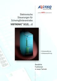
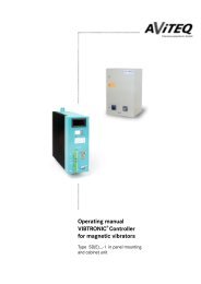
<strong>Operating</strong> <strong>Manual</strong><br />
VIBTRONIC® <strong>Controllers</strong><br />
<strong>for</strong> <strong>Magnetic</strong> <strong>Vibrators</strong><br />
Series SRA(E)...-1<br />
as Panel Mounting Units and Cabinet Units
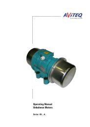
Control and Display Elements<br />
Type label<br />
Potentiometer<br />
Umax<br />
Potentiometer<br />
Umin<br />
Command value<br />
switches<br />
Lock/release<br />
Command value<br />
input<br />
Safety fuse<br />
Mains connection and<br />
<strong>Magnetic</strong> vibrator connection<br />
Status relay
Instruction <strong>Manual</strong> <strong>for</strong> Controller VIBTRONIC ® SRA(E)...-1<br />
Intended use<br />
The VIBTRONIC SRA(E)... -1 type controllers have been designed and constructed<br />
as alternating voltage regulators <strong>for</strong> controlling small-parts conveyor drives, bowl<br />
feeder drives magnetic drives in industrial plants. They operate according to the<br />
principle of voltage regulation (phase regulation).<br />
The controllers have been designed <strong>for</strong> use on a.c. mains networks with a<br />
frequency of either 50 or 60 Hz and a sinusoidal voltage.<br />
Do not use the controllers in environments with a risk of explosion or firedamp.<br />
Observe the in<strong>for</strong>mation regarding the areas of application given in Chapter 1.3.<br />
For your safety<br />
Labelling<br />
This operating manual contains three different types of instructions which point<br />
out important in<strong>for</strong>mation:<br />
DANGER!<br />
The DANGER warning describes procedures or conditions which could result in<br />
dangerous or even fatal consequences <strong>for</strong> the person installing or using the<br />
equipment.<br />
ATTENTION!<br />
NOTE<br />
These instructions are given <strong>for</strong> procedures where there is a danger of damage to<br />
equipment. However, personal injury may also occur as a result<br />
(e.g. in the event of a fire!)<br />
Notes provide in<strong>for</strong>mation about specific procedures. Notes explain<br />
circumstances, clarify terminology or provide tips <strong>for</strong> simplifying processes or<br />
procedures.<br />
Always observe the accident prevention and safety regulations which apply to the<br />
specific area of use.<br />
Important points on dangers<br />
Although the VIBTRONIC controllers have been developed in accordance with all<br />
safety measures, the possibility of operational error cannot be completely<br />
excluded. In the interest of your safety and that of your colleagues, please observe<br />
the following points:<br />
©2001 AViTEQ Vibrationstechnik GmbH Version 02/2002 0–2
DANGER!<br />
When connected to the mains, there are dangerously high voltages within the<br />
controller. Touching electrically live components can be fatal! Be<strong>for</strong>e switching on<br />
the mains power, ensure that it is not possible to touch any live parts. The<br />
electrical connections must be covered!<br />
DANGER!<br />
Disconnect the supply voltage be<strong>for</strong>e conducting any work on the controller or<br />
when replacing a fuse. Observe the applicable regulations from the relevant<br />
liability insurance organisation. Following assembly, check that the protective<br />
conductor connections are functioning correctly.<br />
DANGER!<br />
Explosions can be fatal and result in significant damage to equipment. Do not use<br />
the controller in environments where there is a risk of explosion. SRA(E)...-1 type<br />
controllers have not been designed <strong>for</strong> environments with explosion hazards or<br />
firedamp environments and must not be used in such areas without first taking<br />
appropriate measures.<br />
ATTENTION!<br />
Unsuitable controllers or operation with the incorrect mains voltage/frequency<br />
could result in damage to the small-parts conveyor drive or bowl feeder drive.<br />
Ensure that the connected loads are correct and compare them with the device<br />
type labels!<br />
ATTENTION!<br />
The controller is fitted with a quick-acting safety fuse (F6.3 A / 250 V) <strong>for</strong><br />
protecting the Triac (see also first inside cover page). In case of replacing the fuse,<br />
always use a quick-acting safety fuse of the same type as the controller may<br />
otherwise be destroyed!<br />
0–3 ©1998 AViTEQ Vibrationstechnik GmbH Version 02/2002
Instruction <strong>Manual</strong> <strong>for</strong> Controller VIBTRONIC ® SRA(E)...-1<br />
©2001 AViTEQ Vibrationstechnik GmbH<br />
COPYRIGHT<br />
The SRA(E)... -1 series VIBTRONIC controllers and this operating manual are protected by copyright. Any<br />
reengineering of the units will result in criminal prosecution. All rights to this operating manual are reserved,<br />
including reproduction via photo-mechanical, printing, or any data medium, including in translation.<br />
Reproduction of this operating manual, complete or in part, requires written consent from<br />
AViTEQ Vibrationstechnik GmbH.<br />
VIBTRONIC is a registered and protected trademark of AViTEQ Vibrationstechnik GmbH.<br />
This operating manual supports the intended use and the appropriate operation of VIBTRONIC controllers. For<br />
this purpose, the operating manual includes in<strong>for</strong>mation relating to the use of the product. In particular, the<br />
operating manual does not represent any assurance of specific features or that certain results will be<br />
achieved by the use of the product. Prior to publication, this operating manual has been subjected to<br />
thorough verification. AViTEQ Vibrationstechnik GmbH shall only be liable <strong>for</strong> mistakes in the content of this<br />
operating manual in cases of intentional or gross negligence. This liability shall be restricted to cases where<br />
mistakes in the content render the product worthless or useless, or considerably reduces its value or<br />
usability, <strong>for</strong> its usual purpose or any purpose covered by the contract.<br />
Evidence of mistakes in the content, the damage and the causality regarding both cause and extent of the<br />
claim, must be provided by the purchaser. AViTEQ Vibrationstechnik GmbH shall not be liable <strong>for</strong> damage or<br />
consequential damage resulting from the use of the operating manual. This shall not apply to mistakes in the<br />
content of the operating manual. We are always grateful to receive suggestions and criticism.<br />
Unless otherwise stated, the technical status at the time of the combined delivery of the product and the<br />
operating manual from AViTEQ Vibrationstechnik GmbH shall be regarded as definitive. The product is<br />
subject to technical modification without prior notice. Previous operating manuals shall no longer be valid.<br />
The current version of the General Terms and Conditions <strong>for</strong> Domestic and Foreign Deliveries from<br />
AViTEQ Vibrationstechnik GmbH shall apply, unless otherwise agreed.<br />
Do you have any queries Or any problems with installation and commissioning<br />
Give us a call! We’ll be glad to help you!<br />
AViTEQ Vibrationstechnik GmbH<br />
Im Gotthelf 16<br />
65795 Hattersheim-Eddersheim<br />
Telephone +49 (0) 61 45 / 503 - 0<br />
Fax +49 (0) 61 45 / 503 - 200<br />
Fax Service Hotline +49 (0) 61 45 / 503 - 112<br />
Hattersheim-Eddersheim, Germany, 6. February 2002<br />
2100<br />
©2001 AViTEQ Vibrationstechnik GmbH Version 02/2002 0–4
Content<br />
CONTENTS<br />
1 We are Partners. 1-1<br />
1.1 About this operating manual........................................................................................................................ 1-1<br />
1.2 Product liability and warranty ...................................................................................................................... 1-2<br />
1.3 Operative range ........................................................................................................................................... 1-3<br />
1.4 Installation and operating personnel ............................................................................................................ 1-4<br />
1.5 Repairs......................................................................................................................................................... 1-5<br />
2 Transport, Delivery, Disposal 2-1<br />
2.1 Transport, storage........................................................................................................................................ 2-1<br />
2.2 Extend of delivery ........................................................................................................................................ 2-1<br />
2.3 Disposal ....................................................................................................................................................... 2-2<br />
3 Equipment description 3-1<br />
3.1 Oscillation and mains frequency .................................................................................................................. 3-1<br />
3.2 Scope of operation....................................................................................................................................... 3-1<br />
3.2.1 Command value specification ...................................................................................................................... 3-1<br />
3.2.2 External release ........................................................................................................................................... 3-2<br />
3.2.3 <strong>Operating</strong> messages .................................................................................................................................... 3-2<br />
3.3 Series and versions...................................................................................................................................... 3-2<br />
3.3.1 VIBTRONIC-series........................................................................................................................................ 3-2<br />
3.3.2 Versions and technical data ......................................................................................................................... 3-3<br />
3.3.3 Type designations ........................................................................................................................................ 3-4<br />
4 Installation 4-1<br />
4.1 Mechanical installation ................................................................................................................................ 4-1<br />
4.1.1 Panel mounting unit ..................................................................................................................................... 4-1<br />
4.1.2 Cabinet unit.................................................................................................................................................. 4-2<br />
4.2 Terminal assignments .................................................................................................................................. 4-3<br />
4.2.1 Minimum terminal assignments................................................................................................................... 4-4<br />
4.2.2 Course and fine fill rates .............................................................................................................................. 4-6<br />
4.2.3 External control input................................................................................................................................... 4-6<br />
4.2.4 Switching on/off externally .......................................................................................................................... 4-8<br />
4.2.5 Status relay.................................................................................................................................................. 4-9<br />
4.3 Electrical connection.................................................................................................................................. 4-10<br />
4.3.1 Notes on electrical connections................................................................................................................. 4-10<br />
4.3.2 Vibration- with adjuster, rotary-type knob and scale.................................................................................. 4-11<br />
4.4 Connection to the magnetic drive .............................................................................................................. 4-11<br />
4.4.1 Electromagnetic compatibility(EMV).......................................................................................................... 4-12<br />
4.4.2 Line lengths ............................................................................................................................................... 4-12<br />
5 Commissioning 5-1<br />
5.1 AViTEQ-<strong>Magnetic</strong> drives .............................................................................................................................. 5-1<br />
5.2 Third party drives......................................................................................................................................... 5-1<br />
5.2.1 Setting the nominal vibrator voltage ............................................................................................................ 5-1<br />
5.2.2 Commissioning, step-by-step ...................................................................................................................... 5-2<br />
6 Maintenance 6-1<br />
7 Fault causes and remedies 7-1<br />
8 INDEX i<br />
i ©1998 AViTEQ Vibrationstechnik GmbH Version 02/2002
Instruction <strong>Manual</strong> <strong>for</strong> Controller VIBTRONIC ® SRA(E)...-1<br />
1 We are Partners.<br />
1.1 About this operating manual<br />
This operating manual is intended <strong>for</strong><br />
• installation technicians installing and commissioning the<br />
small-parts conveyor drive or bowl feeder drive or<br />
magnetic vibrator.<br />
• engineers installing the controller, the electrical<br />
connection to the a.c. mains network and the connection<br />
to the small-parts conveyor drive or bowl feeder drive or<br />
the magnetic vibrator.<br />
All work on the controller must only be carried out by<br />
qualified specialist staff (electricians or persons trained in<br />
electrical engineering in accordance with IEC 364<br />
and EN 60204-1).<br />
1<br />
Definitions<br />
• Small-parts conveyor drive or bowl feeder drive, magnetic vibrator (shortened<br />
to: drive or magnetic drive): electromagnetic-mechanical unit <strong>for</strong> operating a<br />
vibration conveyor device<br />
• Vibration conveyor device: unit consisting of the drive and working unit<br />
(trough, tube, helical conveyor, screen, etc.)<br />
• Controller: the electronic control unit (supplied separately) assigned to the<br />
drive <strong>for</strong> connecting to the a.c. mains network<br />
• Cabinet unit: Controller in compact housing <strong>for</strong> wall or frame mounting (type<br />
SRA... -1)<br />
• Panel mounting unit: Controller <strong>for</strong> installation in a switching cabinet or an<br />
enclosed control location (type SRAE... -1)<br />
This operating manual relates to the panel mounting unit. Variations specific to the<br />
cabinet unit are indicated at the appropriate points.<br />
NOTE<br />
Revision date<br />
The version number at the<br />
bottom of each right-hand<br />
page in this operating manual<br />
gives the date when that<br />
page was last updated.<br />
Special symbols in this operating manual<br />
Given earlier in this manual is a description of how safety in<strong>for</strong>mation is indicated<br />
in the text. If you have any questions about safe working practices regarding<br />
controllers and their environment, please call us. We’ll be glad to help you!<br />
For your convenience and ease-of-use, we use the following special symbols in<br />
this operating manual:<br />
• A round dot indicates a list of features and conditions<br />
A “thumbs up” symbol indicates that something needs to be checked.<br />
©2001 AViTEQ Vibrationstechnik GmbH Version 02/2002 1–1
We are Partners. – Product liability and warranty<br />
<br />
A pointing finger indicates steps that must be carried out.<br />
1.2 Product liability and warranty<br />
The controllers represent the state-of-the-art and all the specified functions have<br />
been tested prior to delivery. AViTEQ Vibrationstechnik GmbH carries out product<br />
and market research to aid further development and ongoing improvement. Should<br />
malfunctions or failures occur despite these preventive measures, please contact<br />
our service department. We guarantee that appropriate measures to repair the<br />
fault will be taken immediately.<br />
Warranty conditions<br />
The<br />
General Terms and Conditions<br />
<strong>for</strong> Domestic and Foreign<br />
Deliveries<br />
from AViTEQ Vibrationstechnik<br />
GmbH shall apply in its current<br />
version, unless otherwise<br />
agreed.<br />
We guarantee the functioning of the product as described in this operating manual<br />
<strong>for</strong> a period of 12 months after the date of delivery as stated on the delivery note.<br />
The condition <strong>for</strong> free repair is adherence to the operating manual when storing,<br />
shipping, installing, commissioning and operating the product.<br />
We guarantee that the product is free of faults according to product in<strong>for</strong>mation<br />
published by us, and according to the relevant specifications in this operating<br />
manual. No further product features are guaranteed. AViTEQ Vibrationstechnik<br />
GmbH accepts no responsibility <strong>for</strong> the efficiency of the product or <strong>for</strong> fault-free<br />
operation if used <strong>for</strong> other purposes than those defined on the first right-hand<br />
inside cover page of this operating manual.<br />
Warranty exclusions<br />
Customers and third parties must consult AViTEQ Vibrationstechnik GmbH and<br />
obtain our written consent be<strong>for</strong>e tampering or otherwise interfering with the<br />
product covered by the contract. Otherwise, AViTEQ Vibrationstechnik GmbH shall<br />
not accept liability <strong>for</strong> resultant damage to equipment, injuries and other<br />
consequential damage to the product covered by the contract or to any other<br />
property. Tampering or interfering with the equipment shall also render any<br />
warranty null and void.<br />
AViTEQ Vibrationstechnik GmbH shall not accept liability beyond the warranty<br />
entitlements stated in our terms of business on which the contract is based. This<br />
applies in particular to claims arising from loss of profit or other damage to<br />
customer assets. This restriction shall not apply if the cause of the damage results<br />
from intentional or gross negligence. Neither shall it apply if the customer’s claim<br />
<strong>for</strong> damages is based on the lack of a promised feature. If an obligation under the<br />
contract is violated by negligence, AViTEQ Vibrationstechnik GmbH’s liability shall<br />
be limited to <strong>for</strong>eseeable damage.<br />
The warranty shall be null and void in particular if the equipment is used in<br />
environments, <strong>for</strong> purposes, or connected to power supplies or to control systems<br />
which are not suitable <strong>for</strong> the controllers or which do not con<strong>for</strong>m to standard<br />
levels of up-to-date technology. In particular, liability shall not be accepted <strong>for</strong> any<br />
damage resulting from unsuitable or improper use, faulty installation by the<br />
customer or third parties, normal wear and tear, incorrect or negligent handling or<br />
1–2 ©1998 AViTEQ Vibrationstechnik GmbH Version 02/2002
Instruction <strong>Manual</strong> <strong>for</strong> Controller VIBTRONIC ® SRA(E)...-1<br />
inappropriate operating materials. The same applies to spare parts, chemical,<br />
electrochemical or electrical influences unless the damage can be attributed to<br />
AViTEQ Vibrationstechnik GmbH. Compensation <strong>for</strong> damage other than damage to<br />
the product covered by the contract is excluded except in cases of intentional or<br />
gross negligence or the culpable violation of primary contractual obligations by<br />
AViTEQ Vibrationstechnik GmbH.<br />
In addition, no liability shall be accepted <strong>for</strong> damage to conveyor and automation<br />
plants caused by a malfunction of the product or by mistakes in the content of the<br />
operating manual. No liability shall be accepted <strong>for</strong> damage caused by accessories<br />
not supplied or certified by AViTEQ Vibrationstechnik GmbH. AViTEQ<br />
Vibrationstechnik GmbH shall not be held responsible <strong>for</strong> the violation of patent<br />
rights or other rights of third parties outside the Federal Republic of Germany.<br />
We would like to stress that no liability <strong>for</strong> damage to the product covered by the<br />
contract, or <strong>for</strong> consequential damage to other property shall be accepted if the<br />
damage is caused by non-compliance with safety regulations and/or warning<br />
notices.<br />
1<br />
In concluding the contract, the customer is obliged to state explicitly if the product<br />
covered by the contract is intended <strong>for</strong> private use and will be used by the<br />
customer predominantly <strong>for</strong> this purpose.<br />
The VIBTRONIC controllers described in this operating manual must not be<br />
operated in the United States of America or other countries where US American<br />
law applies, without in<strong>for</strong>ming AViTEQ Vibrationstechnik GmbH.<br />
1.3 Operative range<br />
Type SRA(E)...-1 VIBTRONIC controllers are electrical devices <strong>for</strong> use in industrial<br />
plants and are used to control vibration conveyor devices. The controllers permit<br />
the infinite adjustment of the working stroke on magnetic drives and there<strong>for</strong>e also<br />
the output of vibration conveyor devices.<br />
The controllers must be used together only with AViTEQ small-parts conveyor<br />
drives or bowl feeder drives or the corresponding magnetic drives produced by<br />
other manufacturers in accordance with their intended use. In<strong>for</strong>mation in the<br />
operating manuals <strong>for</strong> the vibration conveyor device and the magnetic vibrator<br />
must also be observed.<br />
The controllers can be operated with magnetic drives from external manufacturers<br />
assuming it has been guaranteed that the controller and the magnetic drive are<br />
equipped <strong>for</strong> the mains voltage and mains frequency specified on the type label.<br />
NOTE<br />
The current of the third party magnetic drive must never be greater than the<br />
current <strong>for</strong> which the controller has been equipped, as given on the type label. If in<br />
doubt, please contact us! The commissioning procedure is described in chapter<br />
5.2.<br />
©2001 AViTEQ Vibrationstechnik GmbH Version 02/2002 1–3
We are Partners. – Installation and operating personnel<br />
Danger<br />
Never use in the following situations:<br />
• Do not use <strong>for</strong> operation in environments with a risk of explosions or firedamp<br />
(explosives, environment containing gas, danger of dust explosions). The<br />
units are not protected against explosion. The level of contamination in the<br />
environment must not exceed level 1 con<strong>for</strong>ming to IEC 664.<br />
• Do not use at ambient temperatures less than -5 and over +45 °C (cabinet<br />
controller unit or panel mounting controller unit), and in tropical climatic<br />
conditions or any condensation (relative air humidity less than 93 % without<br />
condensation or surface water <strong>for</strong>mation). The units are designed <strong>for</strong><br />
operation in moderate climatic environments. The storage temperature must<br />
be within the limits of -20 and +70 °C.<br />
• Do not use in combination with small-parts conveyor drives or bowl feeder<br />
drives, <strong>for</strong> which the controllers are unsuitable.<br />
• Do not use on mains networks and mains frequencies <strong>for</strong> which the<br />
controllers are unsuitable.<br />
NOTE<br />
The controllers are designed <strong>for</strong> use at a maximum height of 1000 m above mean<br />
sea level. For each additional 100 m of starting height, the nominal current is<br />
reduced by 0.5 %!<br />
Connection to mains and to small-parts conveyor drives or bowl feeder<br />
drives<br />
AViTEQ small-parts conveyor drives or bowl feeder drives may only be operated<br />
via the AViTEQ controllers on sinusoidal a.c. mains networks. There is a specific<br />
controller <strong>for</strong> each AViTEQ small-parts conveyor drive or bowl feeder drive model.<br />
Other control and connection options are not included.<br />
ATTENTION!<br />
If a magnetic drive is connected directly to the mains or if an inappropriate<br />
controller is used, the magnetic drive may be destroyed. Ensure that the<br />
appropriate controller is used.<br />
Prior to installation and/or<br />
commissioning, you should<br />
familiarise yourself with all<br />
the specifications <strong>for</strong> the<br />
controller and with the<br />
connection options of the<br />
magnetic drive. Please also<br />
see the chapter on<br />
connecting the magnetic<br />
drives in the operating<br />
manual.<br />
1.4 Installation and operating personnel<br />
It is essential that persons involved in installation, commissioning, assembly,<br />
disassembly, adjustment or maintenance have read and understood this operating<br />
manual in its entirety, in particular the safety notes. If you have any questions, we<br />
will be glad to help!<br />
All work on the controller must only be carried out by qualified specialist staff<br />
(electricians or persons trained in electrical engineering in accordance with IEC<br />
364 and EN 60204-1). Personnel must have sufficient knowledge on the current<br />
1–4 ©1998 AViTEQ Vibrationstechnik GmbH Version 02/2002
Instruction <strong>Manual</strong> <strong>for</strong> Controller VIBTRONIC ® SRA(E)...-1<br />
standards, regulations, accident prevention regulations and operating conditions<br />
to be authorised by the persons responsible <strong>for</strong> the safety of the plant to per<strong>for</strong>m<br />
the necessary activities.<br />
The controllers may only be serviced by authorised and service staff trained by<br />
AViTEQ Vibrationstechnik GmbH, Hattersheim-Eddersheim, Germany.<br />
AViTEQ Vibrationstechnik GmbH, Hattersheim-Eddersheim, Germany is not liable<br />
<strong>for</strong> injuries or damage to property if this is condition is not met.<br />
1.5 Repairs<br />
The controller does not contain any components which can be serviced or<br />
repaired by the installation personnel or operator. Never open the equipment but<br />
send it to AViTEQ Vibrationstechnik GmbH, Hattersheim-Eddersheim, Germany in<br />
the event of a fault.<br />
Please read chapters 6 and 7 if the controller is not functioning correctly.<br />
1<br />
DANGER!<br />
When connected to the mains, there are dangerously high voltages within the<br />
controller and the magnetic drive. Touching electrically live components can be<br />
fatal! Be<strong>for</strong>e switching on the mains power, ensure that it is not possible to touch<br />
any live parts.<br />
©2001 AViTEQ Vibrationstechnik GmbH Version 02/2002 1–5
Transport, Delivery, Disposal – Transport, storage<br />
2 Transport, Delivery,<br />
Disposal<br />
2.1 Transport, storage<br />
• Delivery: The controllers and accessories are delivered in appropriate<br />
packaging to ensure that they reach their destination undamaged.<br />
NOTE<br />
If the packaging is visibly damaged indicating possible damage to the contents,<br />
please contact the courier. In further proceedings, please observe the general<br />
terms and conditions from the courier to avoid jeopardising your claim <strong>for</strong> damages<br />
due to improperly completed <strong>for</strong>ms.<br />
<br />
Storage: Unless special agreements have been made concerning packaging<br />
and storage, the units whether packed or unpacked, must be stored and<br />
transported under "normal" conditions. This means enclosed rooms with<br />
temperatures between -20 and +70 °C, relative air humidity not to exceed 93<br />
% (no condensation), and no mechanical shocks or vibrations.<br />
ATTENTION!<br />
Transportation and storage of the units in inappropriate conditions may cause<br />
irreparable damage. Such damage may not be visible externally. The warranty<br />
from AViTEQ Vibrationstechnik GmbH shall be void in this event, and shall not be<br />
liable <strong>for</strong> any consequential damage.<br />
2.2 Extend of delivery<br />
<br />
<br />
After unpacking, check the delivery note and accompanying documentation<br />
to ensure that all the parts have been supplied and are undamaged. These<br />
parts include the panel mounting controller unit or cabinet controller unit<br />
itself, the operating manual packed together with the controller and <strong>for</strong> panel<br />
mounting units, the separate potentiometer <strong>for</strong> setting the working stroke<br />
with rotary-type knob and scale, and <strong>for</strong> cabinet unit controllers the relevant<br />
plug.<br />
Compare the in<strong>for</strong>mation on the small-parts conveyor drive or bowl feeder<br />
drive type labels with the delivery note and order documentation.<br />
2–1 ©1998 AViTEQ Vibrationstechnik GmbH Version 02/2002
Intruction <strong>Manual</strong> <strong>for</strong> Controller VIBTRONIC ® SRA(E)...-1<br />
<br />
Check that the small-parts conveyor drive or bowl feeder drive and the<br />
controller match. Be<strong>for</strong>e using magnetic vibrators produced by other<br />
manufacturers, you must first ensure that the specifications are suitable <strong>for</strong><br />
operation with the VIBTRONIC controller. If in doubt, please do contact us.<br />
We’ll be glad to help you!<br />
ATTENTION!<br />
The small-parts conveyor drive or bowl feeder drive and controller may be<br />
destroyed if the combination is not permissible. The mains voltage, mains<br />
frequency and vibration frequency must be identical. The nominal current of the<br />
controller must be equal to or greater than the peak current of the magnetic drive.<br />
Only compatible devices may be connected.<br />
2.3 Disposal<br />
Specifications <strong>for</strong> packaging material<br />
All packaging materials should be disposed of in accordance with local regulations<br />
at the delivery destination.<br />
2<br />
Equipment returns<br />
AViTEQ Vibrationstechnik GmbH will accept without charge controllers of type<br />
SRA(E)... -1 delivered in 2001 or later when delivered shipping paid to AViTEQ<br />
Vibrationstechnik GmbH, Hattersheim-Eddersheim, Germany.<br />
Specifications of materials used in the equipment<br />
In the event of disposal by the customer, and when exchanging components, the<br />
relevant local waste and disposal regulations apply and must be observed. We<br />
can accept no responsibility <strong>for</strong> parts and components not disposed of properly.<br />
• The regulations <strong>for</strong> the disposal of electronic parts and components apply to<br />
the disposal of the controller.<br />
• The power semiconductors used (Triac and diode modules) do not contain<br />
beryllium.<br />
More detailed in<strong>for</strong>mation on the materials used is available from us on request. In<br />
case of doubt, please do make use of our recycling service.<br />
NOTE<br />
©2001 AViTEQ Vibrationstechnik GmbH Version 02/2002 2–2
Equipment description – Oscillation rates and mains frequency<br />
3 Equipment description<br />
3.1 Oscillation rates and mains frequency<br />
Type SRA( E) ... -1 controllers are alternating voltage regulators and operate<br />
according to the principle of voltage regulation (phase regulation).<br />
Oscillation rates are specified in “min -1 ” and the oscillation frequency in “Hz”.<br />
NOTE<br />
• <strong>Controllers</strong> <strong>for</strong> vibration conveyor devices with an oscillation rate of<br />
3000 min -1 (50 Hz) at a mains frequency of 50 Hz and<br />
3600 min -1 (60 Hz) at a mains frequency of 60 Hz<br />
are triggered at every second mains half-wave.<br />
• <strong>Controllers</strong> <strong>for</strong> vibration conveyor devices with an oscillation rate of<br />
6000 min -1 (100 Hz) at a mains frequency of 50 Hz and<br />
7200 min -1 (120 Hz) at a mains frequency of 60 Hz<br />
are triggered at every mains half-wave.<br />
The mechanical oscillation frequency (50, 60, 100 or 120 Hz) is factory set and<br />
encrypted in the type designation.<br />
NOTE<br />
This new generation of controllers has been developed in accordance with the<br />
EMC Directive (89/336/EEC) and con<strong>for</strong>ms to the requirements of EN 50081-1 and<br />
EN 50082-2.<br />
3.2 Scope of operation<br />
Type SRA(E)... -1 VIBTRONIC controllers have been designed <strong>for</strong> voltage<br />
regulation. Mains voltage fluctuations have no significant effect on the working<br />
stroke or there<strong>for</strong>e on the conveying capacity across a wide range (±10%).<br />
3.2.1 Command value specification<br />
The command value <strong>for</strong> the working stroke can optionally be set using<br />
• a vibration-width adjuster (potentiometer) or<br />
• an external control input (0...10 V DC, 4...20 mA or 0...20 mA)<br />
3–1 ©1998 AViTEQ Vibrationstechnik GmbH Version 02/2002
Instruction <strong>Manual</strong> fot Controller VIBTRONIC ® SRA(E)...-1<br />
The working stroke changes virtually proportionally with the command value, i.e.:<br />
the greater the command value, the greater the working stroke.<br />
NOTE<br />
3.2.2 External release<br />
The controller can be activated using an electronic release and there<strong>for</strong>e using a<br />
PLC (programmable logic controller), <strong>for</strong> example. This external release can be<br />
made using<br />
• a potential-free contact or<br />
• an external 24 V DC power source or<br />
• an optical coupler.<br />
3.2.3 <strong>Operating</strong> messages<br />
With the cabinet unit, a green light will come on in the mains switch after the<br />
device is switched on.<br />
3.3 Series and versions<br />
3<br />
3.3.1 VIBTRONIC series<br />
Three series of VIBTRONIC controllers are available with different features:<br />
• SRA(E)... series with voltage regulation in cabinet and panel mounting<br />
designs <strong>for</strong> nominal currents up to 6 A, operative ranges 110 and 230 V<br />
• SC(E)... series with voltage regulation in cabinet and panel mounting designs<br />
<strong>for</strong> nominal currents up to 14 A, operative ranges 230, 400 and 500 V<br />
• SD(E)... series with voltage and limit regulation in cabinet and panel mounting<br />
designs <strong>for</strong> nominal currents up to 50 A, operative ranges 230, 400 and 500 V<br />
Only controllers in series SRA(E)...-1 are covered in this operating manual.<br />
NOTE<br />
©2001 AViTEQ Vibrationstechnik GmbH Version 02/2002 3–2
Equipment description – Series and versions<br />
3.3.2 Versions and technical data<br />
The controllers are available in the following variants:<br />
• SRA... cabinet unit (IP 54): enclosed compact housing <strong>for</strong> securing to walls or<br />
frames. Vibration-width adjuster and mains switch are fitted in the front of<br />
the housing.<br />
• SRAE... panel mounting unit (IP 00): controller <strong>for</strong> installing in the switching<br />
cabinet or in closed control locations <strong>for</strong> top hat rail mounting<br />
SRA(E)-C50 ...-1 SRA(E)-C100 ...-1<br />
Mains frequencies<br />
Oscillation rates in a 50 Hz mains<br />
network<br />
Oscillation rates in a 60 Hz mains<br />
network<br />
Mains voltages<br />
(Output voltage range)<br />
Output current<br />
Maximum power loss<br />
in switching cabinet<br />
Soft start<br />
Command value<br />
Status relay<br />
Release input<br />
(factory specification)<br />
50 or 60 Hz<br />
3000 min-1 (50 Hz) 6000 min-1 (100 Hz)<br />
3600 min-1 (60 Hz) 7200 min-1 (120 Hz)<br />
105...115 V (20...100 V)<br />
220...240 V (40...210 V)<br />
0.05...6 A<br />
15 W<br />
0.3 s or 1 s (can be factory set)<br />
Potentiometer 10 kOhm (lin),<br />
0-10 V DC, 0-20 mA, 4-20 mA (adjustable)<br />
Change-over contact 250 V AC / 30 V DC, 1.0 A<br />
Make contact or 24 V DC, can be inverted<br />
Technical data <strong>for</strong> the SRA(E)...-1 controllers<br />
NOTE<br />
The permissible tolerances are ± 10.0 % <strong>for</strong> the mains voltage and ± 0.5 % <strong>for</strong><br />
the mains frequency.<br />
The oscillation frequency is set at the factory be<strong>for</strong>e shipping and must not be<br />
changed by the customer.<br />
NOTE<br />
3–3 ©1998 AViTEQ Vibrationstechnik GmbH Version 02/2002
Instruction <strong>Manual</strong> fot Controller VIBTRONIC ® SRA(E)...-1<br />
3.3.3 Type designations<br />
NOTE<br />
The controllers are designed <strong>for</strong> different voltage ranges according to the table<br />
provided (Technical data). Please see the type label <strong>for</strong> the corresponding voltage<br />
range.<br />
SRAE-C50/01-1-1<br />
Version number<br />
Version:<br />
1=no special functions<br />
2=level scanning system/part overflow<br />
controller<br />
Encryption of the mains voltage range<br />
According to table:<br />
Code Mains voltage range<br />
00 105...115 V<br />
01 220...240 V<br />
Size and vibration frequency:<br />
C50: 3000 / 3600 min -1<br />
C100: 6000 / 7200 min -1<br />
Panel mounting unit<br />
(Cabinet unit without “E”)<br />
Device generation<br />
Controller, with voltage regulation<br />
3<br />
©2001 AViTEQ Vibrationstechnik GmbH Version 02/2002 3–4
Installation – Mechanical installation<br />
4 Installation<br />
4.1 Mechanical installation<br />
The installation steps <strong>for</strong> the two versions are described in the following sections:<br />
• Panel mounting unit in chapter 4.1.1 and<br />
• Cabinet unit in chapter 4.1.2<br />
4.1.1 Panel mounting unit<br />
The controllers are available as panel mounting units (IP 00 con<strong>for</strong>ming to EN<br />
60529) <strong>for</strong> vertical installation in switching cabinets or control cases (<strong>for</strong><br />
dimensions, see diagram on next page). They comprise<br />
• the panel mounting unit <strong>for</strong> top hat rail mounting (Type 35/7.5 EN 50022) and<br />
• the potentiometer with rotary-type knob and scale (delivered loose).<br />
DANGER!<br />
Prior to installation: be<strong>for</strong>e opening the switching cabinet or control case, switch<br />
off the power supply, check that there is no voltage, and protect against accidental<br />
reconnection.<br />
<br />
<br />
Mount the panel mounting unit onto the top hat rail.<br />
Install the supplied potentiometer <strong>for</strong> working stroke adjustment with scale,<br />
rotary-type knob, pointer, and knob cover onto a suitable location (e.g.<br />
switching cabinet door or front of control case).<br />
ATTENTION!<br />
<strong>Controllers</strong> are sensitive to temperature. Ensure that the units are not installed<br />
near external heat sources, such as direct sunshine or radiators. The ambient<br />
temperature must not exceed +45 °C during operation.<br />
<br />
Observe the following minimum distances from neighbouring components:<br />
Distance from ...<br />
Minimum distance<br />
(mm)<br />
top 40<br />
bottom 80<br />
Figure 4.1<br />
Minimum distances from neighbouring components<br />
4–1 ©1998 AViTEQ Vibrationstechnik GmbH Version 02/2002
Instruction <strong>Manual</strong> <strong>for</strong> Controller VIBTRONIC ® SRA(E)...-1<br />
Type label<br />
Type<br />
Item number<br />
Figure 4.2<br />
Weight: 600 g<br />
SRAE...-1 panel mounted version <strong>for</strong> fixing on a top hat rail.<br />
Standard version<br />
4<br />
4.1.2 Cabinet unit<br />
The controllers are supplied in a closed housing (IP 54 con<strong>for</strong>ming to EN 60529).<br />
The cabinet unit is suitable <strong>for</strong> mounting to vertical walls or frames.<br />
The installation is carried out as follows:<br />
<br />
<br />
Use the hole pattern on the dimensioned diagram below as a guide, and fix<br />
the relevant holes <strong>for</strong> the fixing screws.<br />
Hand-tightened the controller to a vibration-free vertical wall or frame.<br />
<strong>Controllers</strong> are sensitive to vibration. Do not screw onto vibrating components, and<br />
under no circumstances to the vibration conveyor device itself.<br />
ATTENTION!<br />
©2001 AViTEQ Vibrationstechnik GmbH Version 02/2002 4–2
Installation – Terminal assignments<br />
Type label<br />
Type<br />
Item number<br />
Weight: 1300 g<br />
Figure 4.3<br />
SRA...-1 cabinet unit design <strong>for</strong> mounting on vertical, vibration-free walls<br />
or frames<br />
Standard version<br />
ATTENTION!<br />
<strong>Controllers</strong> are sensitive to temperature. Ensure that the units are not installed<br />
near external heat sources, such as direct sunshine or radiators. The ambient<br />
temperature must not exceed +45 °C during operation.<br />
4.2 Terminal assignments<br />
The sections below explain the terminal assignments (see terminal plan below) on<br />
the controllers with the relevant options available. This chapter must be read<br />
be<strong>for</strong>e starting the wiring process, and the notes on electromagnetic compatibility<br />
must be observed.<br />
4–3 ©1998 AViTEQ Vibrationstechnik GmbH Version 02/2002
Instruction <strong>Manual</strong> <strong>for</strong> Controller VIBTRONIC ® SRA(E)...-1<br />
Lock/release<br />
Command<br />
Fuse F6,3<br />
Status relay<br />
250 V / 1 A<br />
Mains input<br />
Lock/release<br />
Load<br />
Command<br />
4<br />
Figure 4.4<br />
SRA(E)...-1 terminal plan<br />
Standard version<br />
4.2.1 Minimum terminal assignments<br />
The minimum terminal assignments of a magnetic drive <strong>for</strong> voltage-regulated<br />
operation without external control inputs (<strong>for</strong> details see Chapter 4.2.3) shown in<br />
Figure 4.5.<br />
©2001 AViTEQ Vibrationstechnik GmbH Version 02/2002 4–4
Installation – Terminal assignments<br />
NOTE<br />
For operation without external release switch, terminals 15 and 16 must be<br />
connected by a wire bridge (Chapter 4.2.4). If there is no bridge, there will be no<br />
start signal and the magnetic drive will not function.<br />
PE<br />
1 2 3 4 17 (GND) 18 19 (+10 V) 15 16<br />
Bridge<br />
0<br />
PE L1 N<br />
<strong>Magnetic</strong><br />
drive<br />
(Load)<br />
Potentiometer<br />
10 kOhm (linear)<br />
Figure 4.5 Minimum terminal assignments with mains input (terminals PE, 1 and 2),<br />
magnetic drive (terminals 3 and 4) and vibration-width adjuster<br />
(terminals 17, 18 and 19)<br />
For the cabinet unit version, the plug connection assignments are as per<br />
Figure 4.6.<br />
Pin<br />
Terminal<br />
1 4<br />
2 3<br />
Earth Earth<br />
Figure 4.6<br />
Plug connection assignments <strong>for</strong> the housing socket<br />
NOTE<br />
Only potentiometers (limit value 10 kOhm) with a linear characteristic should be<br />
used as a vibration-width adjuster. Shield the signal lines to guarantee<br />
electromagnetic compatibility if the lines exceed five metres in length.<br />
4–5 ©1998 AViTEQ Vibrationstechnik GmbH Version 02/2002
Instruction <strong>Manual</strong> <strong>for</strong> Controller VIBTRONIC ® SRA(E)...-1<br />
4.2.2 Course and fine fill rates<br />
When using the controller <strong>for</strong> metering and filling procedures, we recommend<br />
connection in accordance with Bild 4.7. In this circuit the two relays K1/K2<br />
function as follows:<br />
• K2 initiates the filling process.<br />
• K1 is activated at 95% full weight.<br />
• At 100% full weight, both relays return to their rest positions.<br />
17 (GND) 18 19 (+10 V)<br />
15 16<br />
Potentiometer (precision<br />
current)<br />
10 kOhm (linear)<br />
0<br />
0<br />
K2<br />
K1 Relay K2 (rest position)<br />
Relay K1 (rest position)<br />
Potentiometer (primary current)<br />
10 kOhm (linear)<br />
Figure 4.7<br />
Course ans fine fil rates<br />
To prevent switching faults, use only gold-plated or hermetically sealed contacts.<br />
4<br />
NOTE<br />
Only potentiometers (limit value 10 kOhm) with a linear characteristic should be<br />
used as the vibration-width adjuster. Shield the signal lines to guarantee<br />
electromagnetic compatibility if the lines exceed five metres in length.<br />
NOTE<br />
4.2.3 External control input<br />
The controller can be operated with an external command value entry (external<br />
control input). The following external command values can be used <strong>for</strong> setting the<br />
working stroke (see Figure 4.8):<br />
• 0...10 V DC, resistance 200 kOhm<br />
• 4...20 mA DC, burden 250 Ohm<br />
• 0...20 mA DC, burden 250 Ohm<br />
Which of the three options you want to use has to be pre-selected by setting the<br />
(blue) spring clip on the control board (see Figure 4.8).<br />
©2001 AViTEQ Vibrationstechnik GmbH Version 02/2002 4–6
Installation – Terminal assignments<br />
0...10 V DC<br />
0 ...20 mA<br />
4 ...20 mA<br />
17<br />
18 19<br />
17<br />
18 19<br />
17<br />
18 19<br />
– +<br />
– +<br />
– +<br />
both bridges open<br />
one bridge closed<br />
both bridges closed<br />
Figure 4.8<br />
Options <strong>for</strong> the external command value specification<br />
A switchable solution is possible <strong>for</strong> special applications (see Figure 4.9). In this<br />
case, a switch or a relay can be used to switch between the external control<br />
inputs or between command value presets using a vibration-width adjuster<br />
(potentiometer), as required.<br />
17 18 19<br />
External<br />
0<br />
Internal<br />
Potentiometer (internal)<br />
10 kOhm (linear)<br />
_ +<br />
0...10 V DC external control input<br />
both bridges open<br />
Figure 4.9<br />
Switchable command value specification<br />
To prevent switching faults, use only gold-plated or hermetically sealed contacts.<br />
NOTE<br />
Only potentiometers (limit value 10 kOhm) with a linear characteristic should be<br />
used as the vibration-width adjuster. Shield the signal lines to guarantee<br />
electromagnetic compatibility if the lines exceed five metres in length.<br />
4.2.4 Switching on/off externally<br />
If no external on/off switching (release) is required, terminals 15 and 16 must be<br />
connected by a wire bridge so that the magnetic vibrator can work.<br />
4–7 ©1998 AViTEQ Vibrationstechnik GmbH Version 02/2002
Instruction <strong>Manual</strong> <strong>for</strong> Controller VIBTRONIC ® SRA(E)...-1<br />
Alternatively, the controller can be switched on and off externally using a switch<br />
(relay), an optical coupler or a direct-voltage signal. The relevant options <strong>for</strong><br />
terminal assignment are given in siehe Figure 4.10.<br />
Switch (potential-free contact)<br />
Power source<br />
Optical coupler<br />
14 (-)<br />
15<br />
16 (+)<br />
14 (-)<br />
15 16 (+)<br />
14 (-)<br />
15 16 (+)<br />
max. 1 mA<br />
0 I<br />
– +<br />
max. 24 VDC<br />
Figure 4.10<br />
Options <strong>for</strong> switching on/off externally<br />
ATTENTION!<br />
NOTE<br />
Destruction of the controller: The maximum permissible load of 1 mA must be<br />
observed.<br />
To prevent switching faults, use only gold-plated or hermetically sealed contacts.<br />
Shield the signal lines to guarantee electromagnetic compatibility if the lines<br />
exceed five metres in length.<br />
4<br />
©2001 AViTEQ Vibrationstechnik GmbH Version 02/2002 4–8
Installation – Terminal assignments<br />
4.2.5 Status relay<br />
The controller has a status relay according to the following illustration:<br />
K<br />
5 6 7<br />
Figure 4.11<br />
Status relay<br />
The following switching states can be analysed:<br />
Terminals<br />
5 and 6<br />
Terminals<br />
6 and 7<br />
Decrease<br />
closed open Mains voltage (terminals 1 and 2) applied and a start signal is issued<br />
simultaneously (terminals 14, 15 and 16).<br />
open closed Mains voltage (terminals 1 and 2) not applied, or no start signal issued<br />
when mains voltage is applied (terminals 14, 15 and 16).<br />
Figure 4.12<br />
Switching states of the status relay<br />
ATTENTION!<br />
The load rating <strong>for</strong> direct current is a maximum of 30 V DC, and <strong>for</strong> alternating<br />
current, a maximum of 250 V AC at a maximum current of 1.0 A.<br />
Destruction of the operational transmitting relay and possibly the controller!<br />
Observe the permissible values given above when dimensioning the load of the<br />
operational transmitting relay.<br />
4–9 ©1998 AViTEQ Vibrationstechnik GmbH Version 02/2002
Instruction <strong>Manual</strong> <strong>for</strong> Controller VIBTRONIC ® SRA(E)...-1<br />
4.3 Electrical connection<br />
4.3.1 Notes on electrical connections<br />
DANGER!<br />
Avoid accidents - observe the regulations! VDE regulations and guidelines from<br />
your power company apply to earth, neutral line and protective circuit<br />
connections. The connection must be made only by trained personnel (certified<br />
electrician or electrically trained person in accordance with IEC 364 and EN<br />
60204-1).<br />
<br />
<br />
<br />
Switch off the current supply.<br />
Verify that no voltages are present.<br />
Ensure that the device cannot be reconnected accidentally.<br />
Mains fuse<br />
For mains protection at the customer’s site, we recommend using a fuse (slowblow)<br />
suitable <strong>for</strong> the nominal current of the connected magnetic drive.<br />
Semi-conductor protection<br />
On the controller conductor boards, there is a fuse link with fine-wire fuse close to<br />
the terminals (see figure, left). If this fuse fails, it must only be replaced with a<br />
fuse with the identical code (F6.3A/250V).<br />
4<br />
ATTENTION!<br />
The wrong fuse could result in damage to the magnetic drive. Observe the<br />
dimensioning of the mains protection at the customer’s site and the fine-wire fuse<br />
fitted.<br />
©2001 AViTEQ Vibrationstechnik GmbH Version 02/2002 4–10
Installation – Connection to the magnetic drive<br />
4.3.2 Vibration-width adjuster, rotary-type knob and<br />
scale<br />
NOTE<br />
Type SRA(E)...-1 controllers are supplied with a vibration-width adjuster (linear<br />
potentiometer with a limit value of 10 kOhm) (Technical data and dimensions siehe<br />
Figure 4.13).<br />
Cap <strong>for</strong> rotary-type knob<br />
(<strong>for</strong> SRAE-C50: red type 332.662,<br />
(<strong>for</strong> SRAE-C100: green type 332.668<br />
Rotary knob type 332.6<br />
Indicator <strong>for</strong> rotary knob type 4332.6<br />
Scale disc type 166.22<br />
*drill to 10 mm<br />
Potentiometer 10 k (linear)<br />
Order number:<br />
Potentiometer add-on kit<br />
<strong>for</strong> SRAE-C50 / ID no:0950501<br />
AViTEQ item number: 23.991<br />
<strong>for</strong> SRAE-C100 / ID no:0950502<br />
AViTEQ item number: 23.992<br />
Figure 4.13<br />
Potentiometer, rotary-type knob, scale <strong>for</strong> variants C50 and C100<br />
4.4 Connection to the magnetic drive<br />
This operating manual is included with each VIBTRONIC controller. A complete<br />
terminal plan is given at the start of Chapter 4.2.1.<br />
<br />
Make all the connections between the mains, controller, command value<br />
circuit and magnetic drive.<br />
4–11 ©1998 AViTEQ Vibrationstechnik GmbH Version 02/2002
Instruction <strong>Manual</strong> <strong>for</strong> Controller VIBTRONIC ® SRA(E)...-1<br />
<br />
Observe the specific features of the equipment in combination with the<br />
possible options, and also observe the terminal assignments given later in<br />
this manual.<br />
DANGER!<br />
When connected to the mains, there are dangerously high voltages within the<br />
controller. Touching electrically live components can be fatal! Be<strong>for</strong>e switching on<br />
the mains power, ensure that it is not possible to touch any live parts. Close the<br />
cover on the control cabinet or close the switching cabinet door(s).<br />
4.4.1 Electromagnetic compatibility (EMC)<br />
The series SRA(E)... -1 controllers have been developed and constructed<br />
con<strong>for</strong>ming to EMC Directive 89/336/EEC. They fulfil the requirements of<br />
standards EN 50081-1 and EN 50082-2.<br />
Observe the in<strong>for</strong>mation regarding the shielding of signal lines described in the<br />
preceding chapters on terminal assignments.<br />
NOTE<br />
NOTE<br />
4.4.2 Line lengths<br />
The line length is defined as the distance between the vibration conveyor device<br />
and the main distributor. Smaller line cross-sections or longer line lengths may<br />
cause faults.<br />
The maximum permissible line length is 200 m.<br />
A line cross-section appropriate to the drive current should be used.<br />
4<br />
<br />
<br />
The line cross-section corresponding to length can be found in the operating<br />
manual <strong>for</strong> the magnetic drive if required.<br />
Please note that only shielded cables should be used <strong>for</strong> signal lines<br />
exceeding the relevant line length specified. The shielding should be fitted on<br />
one side.<br />
The maximum permissible voltage drop between the vibration conveyor device and<br />
the main distributor must not exceed a value of 5 %. If necessary, the line<br />
NOTE<br />
resistance should be calculated and checked.<br />
©2001 AViTEQ Vibrationstechnik GmbH Version 02/2002 4–12
Commissioning – AViTEQ magnetic drives<br />
5 Commissioning<br />
In principle the controllers can be operated both with original AViTEQ vibration<br />
conveyor devices and with equipment from third party manufacturers. This<br />
chapter describes the commissioning procedures required <strong>for</strong> both options.<br />
A requirement <strong>for</strong> the commissioning process is the complete assembly of the<br />
vibration conveyor device with small-parts conveyor drive or bowl feeder drive or<br />
magnetic vibrator.<br />
In addition, all the assembly work must be completed as described and explained<br />
in the previous chapter (chapter 4).<br />
5.1 AViTEQ magnetic drives<br />
The commissioning process <strong>for</strong> the original AViTEQ magnetic drive is best carried<br />
out in accordance with the commissioning steps in the relevant chapter of the<br />
magnetic drive operating manual (small-parts conveyor drive or bowl feeder<br />
drive).<br />
Should any faults occur, please refer to chapter 7 later on in this operating manual.<br />
More in<strong>for</strong>mation can be found in the Troubleshooting chapter in the operating<br />
manual <strong>for</strong> the AViTEQ magnetic drive or <strong>for</strong> the AViTEQ vibration conveyor device.<br />
5.2 Third party drives<br />
5.2.1 Setting the nominal vibrator voltage<br />
The correct term <strong>for</strong> the<br />
controller output voltage is “drive<br />
voltage”. However, as the term<br />
“nominal vibrator voltage” has<br />
become more common, this<br />
expression will be used in this<br />
section.<br />
The nominal vibrator voltages (drive voltages) U V,min and U V,max which can be<br />
measured on terminals 3 and 4 on the controller, are factory set to a fixed value <strong>for</strong><br />
using original AViTEQ equipment.<br />
If a third party magnetic drive is to be used, the setting <strong>for</strong> the nominal vibrator<br />
voltage should be checked and adjusted if necessary.<br />
NOTE<br />
The setting work <strong>for</strong> the nominal vibrator voltage can be carried out by AViTEQ<br />
Vibrationstechnik; in this event, please state the actual nominal vibrator voltage of<br />
your third party device when ordering the controller.<br />
If you want to set the nominal vibrator voltate yourself, please follow the steps<br />
given below <strong>for</strong> the commissioning procedure.<br />
5–1 ©1998 AViTEQ Vibrationstechnik GmbH Version 02/2002
Instruction <strong>Manual</strong> <strong>for</strong> Controller VIBTRONIC ® SRA(E)...-1<br />
5.2.2 Commissioning, step-by-step<br />
For the commissioning process, please also see the commissioning instructions<br />
from the third party manufacturer of your magnetic drive.<br />
We recommend the procedure given below, which should be the same as the<br />
instructions <strong>for</strong> the third party equipment.<br />
1 Prerequisites: Has the work <strong>for</strong> assembling the working unit and the magnetic<br />
drive and <strong>for</strong> cabling <strong>for</strong> the controller been completed<br />
NOTE<br />
For magnetic drives and/or working units not supplied by AViTEQ<br />
Vibrationstechnik, no definite predictions can be made <strong>for</strong> the behaviour of the<br />
vibration device in this operating manual. If necessary, please contact the third<br />
party manufacturer. AViTEQ Vibrationstechnik cannot accept any responsibility <strong>for</strong><br />
the correct functioning of the AViTEQ controller used in combination with vibration<br />
conveyor devices from third party manufacturers.<br />
2 The commissioning procedure must be carried out using the lowest working<br />
stroke: Turn the vibration-width adjuster (potentiometer) on the controller to a<br />
scale value of around 10 %. Or: For an external control input set the lowest<br />
control input value. Now switch on the controller.<br />
NOTE<br />
The commissioning process is carried out at a low working stroke in order to be<br />
able to detect any damage caused by assembly errors <strong>for</strong> the vibration behaviour<br />
of the entire vibration conveyor device which is undetected at this point. Example:<br />
The working unit collides with at neighbouring conveyor components or works in<br />
collision mode.<br />
3 Please listen <strong>for</strong> any hammering noises that indicate the collision mode. This<br />
collision mode may result in the destruction of the drive. If hammering noises<br />
occur, reduce the working stroke by lowering the command value set (turn<br />
potentiometer to the left or reduce external third party command value), until<br />
the hammering noise stops. Turn the trimming potentiometer “U max ” at the<br />
top of the control board approx. 10° anti-clockwise to reduce the vibrator<br />
voltage.<br />
5<br />
Fatal voltage levels! Take appropriate steps (cover live components) to prevent<br />
accidents.<br />
DANGER!<br />
4 Increase the working stroke by gradually turning the vibration-width adjuster<br />
(potentiometer) or by increasing the external command input, until the<br />
maximum value (fully to the right or scale value at “10” on the vibration-width<br />
adjuster or maximum third party command value) has been reached.<br />
©2001 AViTEQ Vibrationstechnik GmbH Version 02/2002 5–2
Commissioning – Third party drives<br />
NOTE<br />
Even if the maximum position on the potentiometer (end scale value “10”) is not<br />
used later on, this position should still be tested during the commissioning process<br />
to ensure that the vibration conveyor device also functions correctly at the<br />
maximum potentiometer-setting or command value.<br />
Connect a voltmeter to a suitable measurement range (recommendation: 750<br />
V AC) to terminals 3 and 4 on the controller. With a digital voltmeter, select<br />
the maximum measurement range (750 V or 1000 V).<br />
Fatal voltage levels! Take appropriate steps (cover live components) to prevent<br />
accidents.<br />
DANGER!<br />
NOTE<br />
Only meters which display the root mean square value should be used <strong>for</strong><br />
measuring the voltage (moving iron instrument or “true RMS”). Other measuring<br />
devices would not produce relevant measurements when measuring the nonsinusoidal<br />
voltage curve. For digital measuring devices, select Š750 V to avoid<br />
incorrect measurements due to the crest factor.<br />
5 Compare the measured vibrator voltage to the manufacturer specifications <strong>for</strong><br />
the magnetic drive and if necessary, set the specified value by adjusting the<br />
trimming potentiometer “U max ” at the top of the control board (see illustration<br />
opposite).<br />
Set the maximum permissible vibrator voltage only with a maximum<br />
command value. To do this, turn the vibration-width adjuster fully to the right<br />
(scale value “10”) or set the maximum value (e.g. 20 mA) <strong>for</strong> an external<br />
control input.<br />
<br />
<br />
To do this, turn the vibration-width adjuster (potentiometer) fully to the left or<br />
the scale value “0”, or set the maximum value <strong>for</strong> an external control input,<br />
e.g. 4 mA.<br />
Then measure the vibrator voltage again. If this is too high, the lower<br />
trimming potentiometer “U min ” at the bottom of the control board can be used<br />
to reduce the minimum vibrator voltage.<br />
Repeat this step until the required voltage <strong>for</strong> U v,min and U v,max has been reached.<br />
There is interaction between the trimming potentiometer “U min ” and “U max ”.<br />
NOTE<br />
6 If the value specified <strong>for</strong> the vibrator voltage cannot be set because this<br />
causes a hammering noise, switch off the device and refer to chapter 7<br />
(Troubleshooting).<br />
5–3 ©1998 AViTEQ Vibrationstechnik GmbH Version 02/2002
Instruction <strong>Manual</strong> <strong>for</strong> Controller VIBTRONIC ® SRA(E)...-1<br />
Collision mode results in the destruction of the magnetic drive! This must there<strong>for</strong>e<br />
be avoided as far as possible when setting the vibrator voltage.<br />
ATTENTION!<br />
7 Measure the vibrator current using a moving iron instrument or using a<br />
device which measures the true room mean square value in a frequency<br />
range of 0 to 500 Hz; compare the values to the manufacturer’s data <strong>for</strong> the<br />
vibration conveyor device being used.<br />
NOTE<br />
Only meters which display the root mean square valueshould be used <strong>for</strong><br />
measuring the current (moving iron or “true RMS” instrument). Other measuring<br />
equipment with a measurement range not equal to 0-500 Hz (without DC) would<br />
not produce relevant measurements when measuring the non-sinusoidal voltage<br />
curve.<br />
DANGER!<br />
Live components. If the equipment is not unplugged, there is a risk of fatal electric<br />
shock. When subsequently carrying out measurements, observe the safety<br />
measures specified.<br />
8 In addition, measure the maximum working stroke and compare the value to<br />
the manufacturer data <strong>for</strong> the vibration device being used.<br />
9 The permissible measurements <strong>for</strong> the nominal vibrator current and voltage<br />
given on the type label must not be exceeded. Otherwise there is a risk of<br />
destruction due to collision mode.<br />
10 If the working stroke specified by the manufacturer is not reached, the natural<br />
frequency of the vibration device should be checked as necessary.<br />
5<br />
©2001 AViTEQ Vibrationstechnik GmbH Version 02/2002 5–4
Maintenance –<br />
6 Maintenance<br />
In general, all AViTEQ controller versions are maintenance free. In dusty<br />
environments, however, there may be dust penetration and deposits may <strong>for</strong>m.<br />
This may result in the deterioration of the cooling system <strong>for</strong> the control<br />
electronics or short circuits as a result of soiled strip conductors.<br />
Check the following at regular intervals:<br />
<br />
<br />
Is there any dust penetration Determine the cause so that measures can be<br />
taken to avoid the problem in future. Clean the controller by vacuuming off the<br />
dust layer, e.g. using an industrial vacuum cleaner.<br />
A suitable cleaning interval should be set depending on the amount of dust in<br />
the environment around the controller.<br />
For cleaning using compressed air, please observe any company regulations<br />
regarding dust disturbance.<br />
NOTE<br />
Disturbed dust can mix with air and <strong>for</strong>m explosive dust-air mixtures. Take all<br />
appropriate measures to eliminate the risk of explosion.<br />
DANGER!<br />
DANGER!<br />
When connected to the mains, there are dangerously high voltages within the<br />
controller. Touching live electrical components can be fatal! Be<strong>for</strong>e cleaning the<br />
controller, switch off the power supply and secure against accidental activation,<br />
including by other staff members. Protect yourself against accidental contact with<br />
adjacent live electrical components or modules.<br />
6–1 ©1998 AViTEQ Vibrationstechnik GmbH Version 02/2002
Instruction <strong>Manual</strong> <strong>for</strong> Controller VIBTRONIC ® SRA(E)...-1<br />
7 Fault Causes and Remedies<br />
DANGER!<br />
Disassembling the controller is potentially fatal and may result in damage to the<br />
device. There are no components within the device which can be maintained or<br />
repaired by the user. Do not attempt to carry out any repairs yourself. Never<br />
disassemble the controller, even if the power supply has been disconnected. In the<br />
event of device malfunction, ship the entire device to AVITEQ Vibrationstechnik,<br />
Hattersheim, Germany. We will ensure that your device is repaired as quickly as<br />
possible.<br />
Fault Cause(s) Remedy<br />
1) Vibration conveyor<br />
device is not<br />
functioning.<br />
2) Vibration conveyor<br />
device output too<br />
low<br />
No mains voltage.<br />
Mains fuse blown.<br />
Supply line interrupted.<br />
Full mains voltage on terminals 3 and 4 (identical<br />
to voltage at terminals 1 and 2).<br />
Triac short-circuit, drive is making buzzing noise.<br />
Controller component(s) (Triac, supply trans<strong>for</strong>mer,<br />
board, etc.) faulty, no voltage at output terminals 3<br />
and 4<br />
Vibration-width adjuster (potentiometer) or its<br />
supply line faulty.<br />
Terminals 15 and 16 are not connected with a<br />
bridge.<br />
Signal line(s) interrupted<br />
Wrong controller chosen.<br />
Voltage at controller output (terminals 3 and 4) too<br />
low<br />
Voltage on drive input too low<br />
Deviation from nominal frequency at in-house<br />
current supply<br />
Correct fault source, check fuse(s)<br />
Replace fuse, check power intake if necessary<br />
Determine cause and replace supply line<br />
Check the connection between the controller and the<br />
drive.<br />
Replace Triac.<br />
Repair required. Send controller to<br />
AViTEQ Vibrationstechnik.<br />
Replace vibration-width adjuster or its supply lines,<br />
consult AViTEQ Vibrationstechnik if necessary<br />
Check switch (relay), external voltage or optical<br />
coupler, if fitted, or use bridge; or connect the terminals<br />
using a switch (relay) or an optical coupler.<br />
Replace signal line(s)<br />
Assign correct controller, check AViTEQ<br />
Vibrationstechnik delivery specifications.<br />
Check mains voltage and controller setting. Check<br />
drive and controller voltage specifications; increase<br />
drive voltage on “Umax” trimming potentiometer if<br />
necessary, or consult AViTEQ Vibrationstechnik.<br />
Supply line too long (... high resistivity), change supply<br />
line (length, diameter), consult AViTEQ<br />
Vibrationstechnik as necessary<br />
Re-tuning required;<br />
check with AViTEQ Vibrationstechnik<br />
Potentiometer (terminals 17, 18 and 19) not<br />
connected, no external control input available.<br />
Controller is supplying incorrect drive frequency;<br />
as a result the drive current Iv is too high and the<br />
fuse may blow.<br />
Table 7<br />
Fault Causes and Remedies<br />
Connect potentiometer or external control input<br />
Repair or re-adjustment required. Send controller to<br />
AViTEQ Vibrationstechnik.<br />
7<br />
©2001 AViTEQ Vibrationstechnik GmbH Version 02/2002 7–1
Fault Causes and Remedies<br />
Fault Cause(s) Remedy<br />
3) Drive is running in<br />
collision mode<br />
(hammering noise).<br />
4) Drive is running at<br />
max. working<br />
stroke, regardless<br />
of the<br />
potentiometer<br />
setting.<br />
5) Potentiometer is not<br />
supplying a virtually<br />
linear working<br />
stroke path<br />
according to the<br />
angle of rotation.<br />
Drive voltage too high<br />
Nominal frequency deviation<br />
in in-house main supply.<br />
Excessive useable weight and/or<br />
natural frequency too low<br />
Wrong controller chosen.<br />
Incorrect vibration frequency set.<br />
Signal line at terminal 17 is interrupted.<br />
Potentiometer connected to wrong terminals<br />
(connected as series resistance).<br />
Table 7 (Forts.)<br />
Fault Causes and Remedies<br />
Check mains voltage and controller setting. Check<br />
drive and controller voltage specifications; reduce drive<br />
voltage on “Umax” trimming potentiometer if<br />
necessary, or consult AViTEQ Vibrationstechnik.<br />
Re-tuning required;<br />
check with AViTEQ Vibrationstechnik<br />
For small-parts conveyor drives and bowl feeder<br />
drives, compare useable weight with the unit weight<br />
on the type label (tray, pan, bar or similar). A new<br />
agreement with AViTEQ Vibrationstechnik may be<br />
required as necessary. Please ask us!<br />
Assign correct controller, check delivery specifications<br />
from AViTEQ Vibrationstechnik.<br />
Check and replace signal line.<br />
Connect potentiometer correctly.<br />
NOTE<br />
The problems listed above mostly relate to the controller. Further faults, caused by<br />
the working unit or the small-parts conveyor drive or bowl feeder drive, can be<br />
found in the appropriate operating manual.<br />
7–2 ©1998 AViTEQ Vibrationstechnik GmbH Version 02/2002
Betriebsanleitung für Steuerung VIBTRONIC ® SRA(E)...-1<br />
8 INDEX<br />
A<br />
Ambient temperatures 1-4<br />
B<br />
Beryllium 2-2<br />
C<br />
Cabinet unit 1-1, 3-3, 4-3<br />
Climatic conditions 1-4<br />
Collision mode 5-4<br />
Controller 1-1<br />
Cooling 6-1<br />
Command value specification 3-, 3-3<br />
Controller 1-1<br />
Copyright 0-4<br />
Course and fine fill rates 4-6<br />
D<br />
Disposal 2-2<br />
Dust 6-1<br />
E<br />
Electrical connection 4-10<br />
EMC Directive(89/336/EWG) 3-1, 4-12<br />
Environments with explosion hazards 0-3, 1-4<br />
External release 3-2<br />
Extent of delivery 2-1<br />
F<br />
Fault causes 7-1<br />
Fuse 0-3, 4-10<br />
G<br />
General Terms and Conditions 0-4<br />
H<br />
Height 1-4<br />
I<br />
Installation 4-1<br />
Installation and operating personnel 1-4<br />
Intented use 0-2<br />
L<br />
Level of contamination 1-4<br />
Line-cross section 4-12<br />
Line lengths 4-12<br />
M<br />
<strong>Magnetic</strong> drive 1-1<br />
<strong>Magnetic</strong> drives by other manufacturers 1-3<br />
<strong>Magnetic</strong> vibrator 1-1<br />
Mains frequency 3-1, 3-3<br />
Mains voltage fluctuations 3-1<br />
Maintenance 6-1<br />
Minimum distances 4-1<br />
Moving iron instrument 5-3, 5-4<br />
N<br />
Natural frequency 5-4<br />
Nominal voltage vibrator 5-1<br />
O<br />
<strong>Operating</strong> messages 3-2<br />
Operative range 1-3<br />
Oscillation rates 3-1, 3-3<br />
8<br />
©2001 AViTEQ Vibrationstechnik GmbH Version 02/2002 i
Stichwortverzeichnis<br />
Output current 3-3<br />
P<br />
Packaging material 2-2<br />
Panel mounting 1-1, 3-3, 4-2<br />
Potentiometer 4-5, 4-11<br />
Power loss 3-3<br />
Product liability 1-2<br />
Protective conductor connections 0-3<br />
R<br />
Repairs 1-5<br />
RMS instrument 5-3, 5-4<br />
S<br />
Safety 0-2<br />
Scope of operation 3-1<br />
Semi-conductor protection 4-10<br />
Small-parts conveyor drive 1-1<br />
Soft start 3-3<br />
Specialist staff 1-1<br />
Status relay 3-3, 4-9<br />
Storage 2-1<br />
Storage temperature 1-4<br />
Swithcing on/off externally 4-8<br />
T<br />
Technical data 3-3<br />
Terminal plan 4-4<br />
Third party drives 5-1<br />
Transport 2-1<br />
True RMS 5-3, 5-4<br />
Type designations 3-4<br />
V<br />
Vibration conveyor device 1-1<br />
Voltage drop 4-12<br />
W<br />
Warranty conditions 1-2<br />
Warranty exclusions 1-2<br />
ii ©1998 AViTEQ Vibrationstechnik GmbH Version 02/2002
Betriebsanleitung für Steuerung VIBTRONIC ® SRA(E)...-1<br />
EC Declaration of Con<strong>for</strong>mity<br />
Manufacturer:<br />
AViTEQ Vibrationstechnik GmbH<br />
Im Gotthelf 16<br />
D-65795 Hattersheim-Eddersheim, Germany<br />
Product description:<br />
<strong>Controllers</strong> <strong>for</strong> small-parts conveyor drives, bowl feeder drives and magnetic<br />
vibrators<br />
Device types:<br />
SRA...-1, SRAE...-1<br />
The products of the specified type series con<strong>for</strong>m to the specifications in the following European<br />
Directive:<br />
89/336/EEC Directive of the Council <strong>for</strong> Con<strong>for</strong>mity of Legal Regulations of Member<br />
States on Electromagnetic Compatibility, updated by 91/263/EEC,<br />
92/31/EEC and 93/68/EEC<br />
The con<strong>for</strong>mity of the products with the European Directives is evidenced by complete compliance<br />
with the following harmonised standards:<br />
DIN EN 50081-1<br />
DIN EN 50082-2<br />
Full technical documentation is available. The operating manual <strong>for</strong> the devices is also available.<br />
The CE symbol has been attached.<br />
The safety notes in the operating manual supplied must be observed.<br />
This declaration assures con<strong>for</strong>mity with the standards and directives cited, but does not represent<br />
any guarantee of specific features.<br />
Hattersheim-Eddersheim, Germany, 1st September 2001<br />
Legally binding signature:<br />
Nickmann, AViTEQ/APB<br />
©1999 AViTEQ Vibrationstechnik GmbH Version 02/2002 4–1
AViTEQ Vibrationstechnik GmbH<br />
Im Gotthelf 16<br />
D-65795 Hattersheim-Eddersheim, Germany<br />
Phone: +49 (0) 61 45 / 5 03 - 0<br />
Fax: +49 (0) 61 45 / 5 03 - 200<br />
Fax Service Hotline: +49 (0) 61 45 / 5 03 - 112<br />
VIB 12.83 / 0102 EN