Operating Manual Unbalance Motors - AViTEQ Triltechniek
Operating Manual Unbalance Motors - AViTEQ Triltechniek
Operating Manual Unbalance Motors - AViTEQ Triltechniek

Create successful ePaper yourself
Turn your PDF publications into a flip-book with our unique Google optimized e-Paper software.
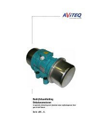
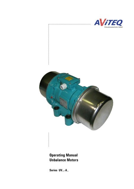
<strong>Operating</strong> <strong>Manual</strong><br />
<strong>Unbalance</strong> <strong>Motors</strong><br />
Series UV...-A_
...........................................................................................................................................................................................................................................................................................................................................................................................................<br />
Intended Use<br />
<strong>AViTEQ</strong> unbalance motors of the series UV...-A_ that are described in this operating<br />
manual are designed as single or double drives for normal areas and for areas with<br />
the presence of combustible dust (zone 21 and 22) with the approval:<br />
LCIE 07 ATEX 6020 X<br />
II 2 D tD A21 IP66 T ...°C 1<br />
as drives for vibration (conveyor) devices for discharging, conveying, feeding,<br />
compacting, loosening, dosing, and/or screening of bulk materials.<br />
As a three-phase cage motor, the unbalance motor is suited for use with 50 Hz or 60<br />
Hz three-phase mains supplies. Some special unbalance motor types are design-ed<br />
and built for single-phase operation for use with 50 Hz or 60 Hz mains supplies.<br />
Don’t operate the unbalance motor of the standard series UV...-A_ , as described in<br />
this operating manual, in areas with explosive gas atmospheres. The unbalance<br />
motor isn’t designed and approved for this case.<br />
For areas with explosive gas atmospheres there is a special series of <strong>AViTEQ</strong><br />
unbalance motors that are described in a separate operating manual.<br />
Please also observe the additional remarks about the intended use that are specified<br />
in chapter 1.3!<br />
When installing the unbalance motor to a working unit (trough, tube, screen etc.) it is<br />
to be made certain that no ignition sources result from colliding components. The<br />
vibration (conveyor) device (unit of unbalance motor and working unit) must be able<br />
to oscillate freely without effecting neighboring components.<br />
<strong>AViTEQ</strong> Vibrationstechnik GmbH does not take responsibility for injuries or damages<br />
which arise as a result of the use or the application of this product, which deviates<br />
from the data in the operating manual.<br />
1<br />
The maximum surface temperature is listed in the table 3.1 on page 24.<br />
...........................................................................................................................................................................................................................................................................................................................................................................................<br />
2 / 48
<strong>Operating</strong> <strong>Manual</strong> for <strong>AViTEQ</strong> <strong>Unbalance</strong> <strong>Motors</strong>, Series UV...-A_<br />
...........................................................................................................................................................................................................................................................................................................................................................................................................<br />
For your Safety<br />
You will find three different types of symbols in this operating manual which are<br />
intended to point out important information:<br />
DANGER!<br />
The danger warning describes procedures or conditions which could lead to<br />
dangerous and even life-threatening consequences for the person installing or using<br />
the equipment.<br />
You will find this information with procedures in which a danger of damage to<br />
equipment exists. This damage could also result in injury to personnel (e.g., from a<br />
fire or an explosion!).<br />
ATTENTION!<br />
¡¡¡¡¡¡¡¡¡¡¡¡¡¡¡¡¡¡¡¡¡¡¡¡¡¡¡¡¡¡¡¡¡¡¡¡¡¡¡¡¡¡¡¡¡¡¡¡¡¡¡¡¡¡¡¡¡¡¡¡¡¡¡¡¡¡¡¡¡¡¡¡¡¡¡¡¡¡¡¡¡¡¡¡¡¡¡¡¡¡¡¡¡¡¡¡¡¡¡¡¡¡¡¡¡¡¡¡¡¡¡¡¡¡¡¡¡¡¡¡¡¡¡¡¡¡¡¡¡¡¡¡<br />
NOTE<br />
Notes provide information regarding individual tasks. Notes explain circumstances,<br />
clarify terminology or provide tips for simplifying processes or procedures.<br />
Even though the <strong>AViTEQ</strong> unbalance motors were developed with all safety measures<br />
for your protection, handling errors may occur. In the interest of your safety and that<br />
of your colleagues, please observe the following information:<br />
DANGER!<br />
When the unit is connected to the mains, a perilous voltage is present inside of the<br />
terminal box of the unbalance motor. Touching electrically live components can be<br />
lethal! Before switching on mains power, ensure that no live parts can be touched!<br />
Close the cover of the terminal box and check that all cable glands and all insulations<br />
are undamaged!<br />
DANGER!<br />
Never operate the unbalance motor without its protective hoods! Rotating<br />
centrifugal weights that are not covered can lead to perilous injuries in the case of<br />
touching them! Furthermore, with the types UVE 7,7Y-A1; UVE 7X-A1 and UVE 3W-<br />
A1 the protective hoods are part of the bearing shield construction.<br />
Check that the protective hoods are mounted properly before you switch on the drive!<br />
DANGER!<br />
Explosions can lead to perilous injuries and cause great damage to property!<br />
<strong>AViTEQ</strong> unbalance motors of the series UV...-A_ without an ATEX-type examination<br />
certification for explosive gas atmospheres, as described in this operating manual,<br />
must not be operated in areas with potentially explosive atmospheres consisting of a<br />
gas-, a vapour-, or a mist-air-mixture!<br />
...........................................................................................................................................................................................................................................................................................................................................................................................<br />
© 2009 <strong>AViTEQ</strong> Vibrationstechnik GmbH Version 04/2009 3 / 48
...........................................................................................................................................................................................................................................................................................................................................................................................................<br />
DANGER!<br />
If you operate the unbalance motor in an area with the presence of combustible dust,<br />
never open the cover of the terminal box, as long as voltage is present at the<br />
terminals inside of the terminal box, because this is an ignition source and as a result<br />
may lead to an ignition of a potentially explosive atmosphere consisting of a dust-airmixture!<br />
DANGER!<br />
Inadequate installation may cause the unbalance motor to fall down possibly causing<br />
injuries. Ensure that the unbalance motor is bolted on tight to the working unit and<br />
take appropriate steps to ensure that the unbalance motor cannot fall down!<br />
Remaining under the unbalance motor or the vibration (conveyor) device is not<br />
allowed!<br />
DANGER!<br />
Parts that collide with other parts can lead to ignition sources. Before first<br />
commissioning, make sure that the vibration (conveyor) device can oscillate without<br />
colliding with other parts and that all screws are tightened correctly!<br />
DANGER!<br />
After switching off, an unbraked unbalance motor may excite the natural frequency<br />
of its support before coming to a halt. Make sure that the vibration (conveyor) device<br />
cannot jump out of its support! Always use a braking unit for unbalance motors of<br />
sizes UVG… and larger.<br />
DANGER!<br />
Danger of injuries! During operation the motor housing heats up. Expect surface<br />
temperatures up to +135°C!<br />
ATTENTION!<br />
Every unbalance motor must be operated with a separate motor-protective<br />
circuit breaker! It is not allowed to add up the currents of several unbalance<br />
motors and then operate them with a common motor-protective circuit breaker! The<br />
motor-protective circuit breaker has to be set to the value of the rated current<br />
(nominal current) of the unbalance motor, as it is shown on the type label of the<br />
unbalance motor!<br />
<strong>Operating</strong> with two drives, both drives have to be connected in a way that if one<br />
drive is switched off the second drive has to be switched off too. A single drive<br />
operation is not allowed in the case of double drives and may lead to a destruction<br />
of the unbalance motors and/or the vibration (conveyor) device! Always observe this!<br />
...........................................................................................................................................................................................................................................................................................................................................................................................<br />
4 / 48
<strong>Operating</strong> <strong>Manual</strong> for <strong>AViTEQ</strong> <strong>Unbalance</strong> <strong>Motors</strong>, Series UV...-A_<br />
...........................................................................................................................................................................................................................................................................................................................................................................................................<br />
ATTENTION!<br />
The unbalance motors are normally delivered without a connexion cable. Select,<br />
depending upon your case of application, a connexion cable with a suitable wire and<br />
cable cross section, permissible in accordance with the standards that guarantees<br />
the degree of protection (IP66) at the cable gland.<br />
If the unbalance motor is operated in areas with the presence of combustible dust<br />
(zone 21 or 22), the temperature of the connexion cable must not exceed<br />
+120°C near the cable gland. Choose a connexion cable that is suitable for a<br />
maximum temperature of +120°C. In case of doubt, please contact us.<br />
ATTENTION!<br />
If the unbalance motor is operated in areas with the presence of combustible dust<br />
(zone 21 or 22), it is mandatory to connect and use the present PTC thermistor in<br />
order to restrict the maximum temperature of the unbalance motor to +120°C or<br />
+135°C, depending on the type of the unbalance motor!<br />
ATTENTION!<br />
Unsuitable controllers or operation with the incorrect mains voltage could result in<br />
damage to the unbalance motor and is not allowed. Ensure that the connected loads<br />
are correct and compare the type labels of the unbalance motor and the braking unit!<br />
It is totally prohibited that the current consumption of the unbalance motor exceeds<br />
the value of the nominal current specified on the type label!<br />
ATTENTION!<br />
The permissible mains frequency is stated on the motor’s type label. When operating<br />
with a different frequency – e.g., when using a frequency converter – ensure that<br />
the permissible mains frequency is not exceeded without consulting <strong>AViTEQ</strong>.<br />
Disregarding this may lead to premature failure of the unbalance motor.<br />
ATTENTION!<br />
If the unbalance motor is operated in areas with the presence of combustible dust<br />
(zone 21 or 22, the sealing (o-ring) of the cover of the terminal box and the sealings<br />
of the protective hoods must be replaced every 2 years. If damages are visible the<br />
sealings must be replaced immediately!<br />
ATTENTION!<br />
Prior to welding work on or near the vibration (conveyor) device, all supply lines to<br />
the unbalance motor (especially the protective earth) must be disconnected from the<br />
mains supply. Otherwise the unbalance motor may be damaged!<br />
...........................................................................................................................................................................................................................................................................................................................................................................................<br />
© 2009 <strong>AViTEQ</strong> Vibrationstechnik GmbH Version 04/2009 5 / 48
...........................................................................................................................................................................................................................................................................................................................................................................................................<br />
NOTE<br />
<strong>AViTEQ</strong> normally delivers the unbalance motors with a mounted cable gland. If the<br />
cable gland should be missing or damaged, please choose a suitable cable gland that<br />
fulfills the requirements for areas with the presence of combustible dust (zone 21<br />
and 22) and that has an approval for the equipment group II, category 2D and at<br />
least IP66 (designation: II 2D IP66).<br />
NOTE<br />
<strong>Operating</strong> the unbalance motors with a frequency converter with pulse-width<br />
modulation (PWM) is allowed, if the following general conditions are observed:<br />
a) The allowed frequency range for the output frequency of the frequency<br />
converter is 20 up to 50 Hz with a 50 Hz-mains frequency and 20 up to 60<br />
Hz with a 60 Hz-mains frequency. Further the unbalance motor must be<br />
operated with a constant torque (linear voltage-frequency-curve) and has<br />
to be protected against overcurrent.<br />
Further following terms have to be observed, if the unbalance motor is operated in<br />
areas with the presence of combustible dust:<br />
b) The unbalance motor is only allowed to be operated in the zone 21 or 22.<br />
c) The unbalance motor must have a PTC thermistor that must be controlled by<br />
a PTC thermistor triggering unit that has an ATEX-approval. An exceed-ing<br />
of the allowed surface temperature must lead to a switching off of the<br />
unbalance motor.<br />
If the above defined terms are met, a motor-protective circuit breaker with a bi-metal<br />
(circuit breaker with an adjustable overcurrent release) is not needed. In fact, a<br />
motor-protective circuit breaker with a bi-metal that is located between an<br />
unbalance motor and a frequency converter is often activated by mistake by the<br />
harmonics that are generated by the frequency converter and therefore this<br />
protection device is not useful!<br />
NOTE<br />
Depending on the construction of the working unit and the acoustic properties of the<br />
material transported, the sound pressure level of the operational unbalance motor<br />
may exceed 70 dB(A). It is the operator’s responsibility to ensure adherence to the<br />
sound pressure level permitted by means of suitable noise protection measures!<br />
NOTE<br />
If a thermal overcurrent release is used, it has to be set to the nominal current that is<br />
shown on the type label of the unbalance motor. The allowed number of operating<br />
cycles by operating the unbalance motor with a thermal overcurrent release is 15<br />
cycles per hour with a duty cycle of 100% and 60 cycles per hour with a duty cycle<br />
of 40%.<br />
NOTE<br />
Remove all loose parts from the vibration (conveyor) device before starting the<br />
unbalance motor.<br />
...........................................................................................................................................................................................................................................................................................................................................................................................<br />
6 / 48
<strong>Operating</strong> <strong>Manual</strong> for <strong>AViTEQ</strong> <strong>Unbalance</strong> <strong>Motors</strong>, Series UV...-A_<br />
...........................................................................................................................................................................................................................................................................................................................................................................................................<br />
...........................................................................................................................................................................................................................................................................................................................................................................................<br />
© 2009 <strong>AViTEQ</strong> Vibrationstechnik GmbH Version 04/2009 7 / 48
...........................................................................................................................................................................................................................................................................................................................................................................................................<br />
© 2009 <strong>AViTEQ</strong> Vibrationstechnik GmbH<br />
COPYRIGHT<br />
The <strong>AViTEQ</strong> unbalance motors of the series UV...-A_ and this operating manual are protected by copyright. Any<br />
reengineering of the units will result in criminal prosecution. All rights of this operating manual are reserved,<br />
including reproduction via photo mechanical, print, data or any other possible medium, as well as in translation.<br />
Reproduction of this operating manual, complete or in part, requires the written consent of <strong>AViTEQ</strong> Vibrationstechnik<br />
GmbH.<br />
VIBTRONIC® is a registered and protected trademark of <strong>AViTEQ</strong> Vibrationstechnik GmbH.<br />
This operating manual supports the intended use and appropriate deployment of <strong>AViTEQ</strong> unbalance motors. For this<br />
purpose, the operating manual describes details that are significant for the product's operation.<br />
<strong>AViTEQ</strong> Vibrationstechnik GmbH is liable for textual errors in the operating manual only where intent and gross<br />
negligence are demonstrated. In such cases, liability is limited to the effects the textual errors have on the product<br />
specified in the contract and other associated products produced by <strong>AViTEQ</strong> Vibrationstechnik GmbH as well as<br />
required products produced by <strong>AViTEQ</strong> Vibrationstechnik GmbH which are used in technical combination. This<br />
aforementioned liability is limited to cases in which the value or functionality of the agreed upon characteristic of<br />
the product specified in the contract is vitiated or considerably diminished. This does not apply if liability for loss of<br />
life or limb or loss of health is mandatory.<br />
The textual errors, the damages as well as the justification and resulting causality underlying the liability claim are<br />
to be proven by the purchaser. In particular, <strong>AViTEQ</strong> Vibrationstechnik GmbH is not liable for damages or<br />
consequential damages resulting from the incorrect use of the operating manual. This does not apply to faulty<br />
content of the operating manual. This does not apply if liability for loss of life or limb or loss of health is mandatory.<br />
We are always grateful for suggestions and criticism!<br />
Unless otherwise stated, the relevant state of engineering is that at the time of the combined delivery of the<br />
product and the operating manual from <strong>AViTEQ</strong> Vibrationstechnik GmbH. The product is subject to technical<br />
changes without prior notice. Previous operating manuals no longer apply.<br />
The General Conditions of Delivery Domestic and Abroad of <strong>AViTEQ</strong> Vibrationstechnik GmbH apply in their current version.<br />
Do you have questions Or problems with installation and commissioning<br />
Give us a call! We'll be glad to help you!<br />
<strong>AViTEQ</strong> Vibrationstechnik GmbH<br />
Im Gotthelf 16<br />
65795 Hattersheim-Eddersheim<br />
Germany<br />
Phone …………….. +49 / 6145 / 503 - 0<br />
Fax ………………… +49 / 6145 / 503 - 200<br />
Fax ………………… +49 / 6145 / 503 - 112 (Service-Hotline)<br />
E-Mail ……………. service@aviteq.de<br />
Hattersheim-Eddersheim, 20 th of April 2009<br />
...........................................................................................................................................................................................................................................................................................................................................................................................<br />
8 / 48
<strong>Operating</strong> <strong>Manual</strong> for <strong>AViTEQ</strong> <strong>Unbalance</strong> <strong>Motors</strong>, Series UV...-A_<br />
...........................................................................................................................................................................................................................................................................................................................................................................................................<br />
CONTENT<br />
1 We are Partners 10<br />
1.1 About this <strong>Operating</strong> <strong>Manual</strong> ................................................................................................ 10<br />
1.2 Product Liability and Warranty .............................................................................................. 11<br />
1.3 Operative Range ................................................................................................................... 13<br />
1.4 Installation and <strong>Operating</strong> Personnel ..................................................................................... 13<br />
1.5 Safety Instructions regarding the <strong>Operating</strong> Location ............................................................ 14<br />
1.6 Built-in Safety Systems ...…………......................................................................................... 14<br />
1.7 Safety Precautions and Responsibilities of the Operator ........................................................ 14<br />
1.8 EC-Directives ....................................................................................................................... 15<br />
2 Transport, Storage 16<br />
2.1 Extent of Delivery ............................................................................................................... 17<br />
2.2 Disposal .................................................…......................................................................... 17<br />
2.2.1 Packing Materials ............................................................................................................... 17<br />
2.2.2 Returning the Device ........................................................................................................... 18<br />
2.2.3 Materials used in the Units .................................................................................................. 18<br />
3 Device Specification 19<br />
3.1 Principle of Operation .......................................................................................................... 19<br />
3.2 Construction ....................................................................................................................... 21<br />
3.3 Sizes ................................................................................................................................... 22<br />
3.3.1 Type Designation ................................................................................................................. 22<br />
3.3.2 Housing Sizes and Mounting Hole Dimensions .......…………................................................... 22<br />
3.4 Sound Pressure Level .......................................................................................................... 24<br />
3.5 Surface temperatures ......................................................................................................... 24<br />
4 Installation 25<br />
4.1 Mechanical Installation ........................................................................................................ 25<br />
4.1.1 General Remarks .................................................................................................................. 25<br />
4.1.2 Attachment of the <strong>Unbalance</strong> Motor ................................................................................... 25<br />
4.2 Mains Connexion ................................................................................................................ 28<br />
4.2.1 Safety Instructions regarding the Mains Connexion ............................................................ 28<br />
4.2.2 Overload Protection ............................................................................................................. 29<br />
4.2.3 Connexion Cable ................................................................................................................. 29<br />
4.2.4 Connexion Diagram ............................................................................................................ 30<br />
4.2.5 Terminal Connexions inside the Terminal Box ..........................................…......................... 30<br />
4.2.6 Single Phase Operation ............…......................................................................................... 32<br />
5 Commissioning 33<br />
5.1 Adjusting the Centrifugal Force ..............................…........................................................... 33<br />
5.2 First Commissioning ............................................................................................................. 36<br />
5.2.1 Single Drive ...…................................................................................................................... 36<br />
5.2.2 Double Drive .....…................................................................................................................ 36<br />
5.2.3 Final Check ..........…............................................................................................................. 37<br />
6 Maintenance 38<br />
6.1 Regular Checks .................................................................................................................... 38<br />
6.2 Replacing the Sealings ................................................................................................... 38<br />
6.3 Bearing Lubrication ............................................................................................................... 39<br />
6.4 Cleaning .............................................................................................................................. 42<br />
6.5 Repairs ................................................................................................................................ 43<br />
7 Troubleshooting 44<br />
8 Index 45<br />
...........................................................................................................................................................................................................................................................................................................................................................................................<br />
© 2009 <strong>AViTEQ</strong> Vibrationstechnik GmbH Version 04/2009 9 / 48
...........................................................................................................................................................................................................................................................................................................................................................................................................<br />
1 We are Partners<br />
1.1 About this <strong>Operating</strong> <strong>Manual</strong><br />
For whom<br />
This operating manual is intended for<br />
• Installation technicians installing and/or commissioning the unbalance motor.<br />
• Technicians installing the controller, the electrical connexion to the a.c. mains<br />
network and the connexion to the unbalance motor.<br />
All work on the electrical installation must only be carried out by qualified personnel<br />
(electricians or persons trained in electrical engineering according to EN 60204-1).<br />
Additional publications<br />
Supplements to this operating manual<br />
• Terminal diagram sheet inside the motor’s terminal box<br />
• Note(s) (adhesive label(s)) on the unbalance motor<br />
• ATEX-Type Examination Certificate<br />
• Data sheet of the unbalance motor<br />
NOTE<br />
This operating manual refers only to the unbalance motors of the type: „UV..-A_“ in<br />
standard design! For unbalance motors in special version for areas with the presence<br />
of combustible dust or areas with explosive gas atmospheres of the series: „eUV..-<br />
A_“ a separate operating manual is existing.<br />
Definitions<br />
• <strong>Unbalance</strong> motor: Electric motor with centrifugal weights for operating<br />
a vibration (conveyor) device<br />
• Working unit:<br />
The conveyor unit (trough, tube or screen etc.) in<br />
multiple variations<br />
• Vibration (conveyor) device: <strong>Unbalance</strong> motor with the assembled working unit<br />
• Braking unit:<br />
A separate deliverable electrical controller for the<br />
unbalance motor for connecting it with the mains<br />
supply<br />
Revision date<br />
On the bottom on the right hand<br />
side page of this operating<br />
manual, the version number tells<br />
you the date when the page was<br />
last updated.<br />
Special symbols in this operating manual<br />
Earlier in this manual, you should have learned how we indicate safety notices. If you<br />
have any questions about safe work practices regarding the unbalance motor you<br />
should give us a call!<br />
For your convenience and orientation, we use the following special indicators in this<br />
operating manual:<br />
<br />
<br />
<br />
A round bullet indicates a listing of characteristics and conditions.<br />
The upward showing thumb tells you to check something, or read a summary.<br />
The pointing finger indicates steps that you have to carry out.<br />
...........................................................................................................................................................................................................................................................................................................................................................................................<br />
10 / 48
<strong>Operating</strong> <strong>Manual</strong> for <strong>AViTEQ</strong> <strong>Unbalance</strong> <strong>Motors</strong>, Series UV...-A_<br />
...........................................................................................................................................................................................................................................................................................................................................................................................................<br />
1.2 Product Liability and Warranty<br />
The unbalance motors correspond to the current State of Engineering and have been<br />
tested for each of its guaranteed functions prior to delivery. <strong>AViTEQ</strong><br />
Vibrationstechnik GmbH carries out product and market research to aid further<br />
development and continuous improvement. Should malfunctions or failures occur<br />
despite these preventative measures, please contact our service department! We<br />
guarantee that appropriate measures for the repair of the defect will be taken<br />
immediately.<br />
Conditions of Warranty<br />
The “General Conditions of Delivery<br />
Domestic and Abroad” of <strong>AViTEQ</strong><br />
Vibrationstechnik GmbH apply in<br />
their current version.<br />
We guarantee that the product is free of defects within the scope of the technical<br />
product specifications published by <strong>AViTEQ</strong> Vibrationstechnik GmbH as well as<br />
technical specifications provided in this operating manual. No declarations of other<br />
product features or claims regarding additional characteristics are provided. <strong>AViTEQ</strong><br />
Vibrationstechnik GmbH is not liable for the economic efficiency of the product or<br />
proper functionality when used for applications other than the purpose defined for<br />
the product as specified on the first, left-hand inner page in the front of this<br />
operating manual.<br />
Warranty Exclusions<br />
Customers and third parties must not undertake work inside or otherwise interfere<br />
with the product, except the works that are described in this operating manual.<br />
Otherwise, liability for devices, persons and other consequential damages of any<br />
type to the product specified in the contract and other legal assets is precluded,<br />
provided <strong>AViTEQ</strong> Vibrationstechnik GmbH is not co-responsible. Entering into or interfering<br />
with the equipment also renders any warranty null and void.<br />
<strong>AViTEQ</strong> Vibrationstechnik GmbH does not accept liability beyond the warranty<br />
entitlements stated in our terms of business on which the contract is based. This<br />
applies in particular to claims arising from loss of profit or other damage to purchaser/customer<br />
assets. This liability limitation does not apply unless the damage<br />
was intentional or caused through gross negligence and unless liability for loss of life<br />
or limb or loss of health is mandatory. This also does not apply when the purchaser/customer<br />
makes a claim for damages based on an incorrect claim of a<br />
characteristic or an agreed-upon characteristic. In the event of culpable violation of<br />
principle contractual obligations, <strong>AViTEQ</strong> Vibrationstechnik GmbH is also liable for<br />
criminal intent and gross negligence on the part of non-managing employees and for<br />
mild negligence. In the latter case, this is limited to the contract-typical, judicious,<br />
predicable damages.<br />
Warranty is excluded in particular when the units are used in environments, for<br />
purposes, or connected to power supplies or to control systems that are not suitable<br />
for the unbalance motors or that do not represent the common state of technology.<br />
In particular, no warranty is provided for damages caused by unsuitable or incorrect<br />
use, incorrect mounting or commissioning by the purchaser/customer or third parties,<br />
natural wear, faulty or careless handling or unsuitable operating materials. The same<br />
applies for replacement parts, chemical, electrochemical or electrical influences<br />
provided they cannot be attributed to <strong>AViTEQ</strong> Vibrationstechnik GmbH and its<br />
employees. Claims made for damages to objects other than that which is specified in<br />
the contract, so-called deficiency losses, are limited. In this case, <strong>AViTEQ</strong><br />
Vibrationstechnik GmbH is liable, regardless of the legal basis, only in the cases of<br />
...........................................................................................................................................................................................................................................................................................................................................................................................<br />
© 2009 <strong>AViTEQ</strong> Vibrationstechnik GmbH Version 04/2009 11 / 48
...........................................................................................................................................................................................................................................................................................................................................................................................................<br />
intent, gross negligence on the part of the owner/of its management or managing<br />
employee in the event of culpable loss of life or limb or health, in the event of<br />
deficiencies which are fraudulently concealed or the absence of which <strong>AViTEQ</strong><br />
guaranteed, in the event of deficiencies of the delivered object, provided liability is<br />
provided in accordance with the product liability law for injury to persons and<br />
damages to materials or other special legal requirements.<br />
Likewise, no warranty is provided for damages to conveyance and automation<br />
systems which are the result of a malfunction of the product or a textual error in the<br />
operating manual. The warranty excludes damages which are the result of<br />
accessories not supplied or certified by <strong>AViTEQ</strong> Vibrationstechnik GmbH. <strong>AViTEQ</strong><br />
Vibrationstechnik GmbH is not responsible for the violation of patent rights and other<br />
titles of third parties outside of the Federal Republic of Germany.<br />
We would like to point out that we are not liable for damage to the product subject<br />
to the contract, or for consequential damage to other property, if the damage is<br />
caused by non-observation of safety regulations and/or warning notices.<br />
When entering the contract, the purchaser/customer is obliged to point out explicitly<br />
if the product is intended for private use and will be used by the purchaser/customer<br />
predominantly for this purpose.<br />
The unbalance motors described in this operating manual must not be operated<br />
without consultation and corresponding release by <strong>AViTEQ</strong> Vibrationstechnik GmbH<br />
in the United States of America and other countries where US American laws are<br />
applicable.<br />
...........................................................................................................................................................................................................................................................................................................................................................................................<br />
12 / 48
<strong>Operating</strong> <strong>Manual</strong> for <strong>AViTEQ</strong> <strong>Unbalance</strong> <strong>Motors</strong>, Series UV...-A_<br />
...........................................................................................................................................................................................................................................................................................................................................................................................................<br />
1.3 Operative Range<br />
<strong>AViTEQ</strong> unbalance motors are designed and used as single or double drives for<br />
vibration (conveyor) devices for discharging, conveying, feeding, compacting, loosening,<br />
dosing, and/or screening of bulk materials. The unbalance motors are not<br />
intended for any other purposes.<br />
As a three-phase cage motor, the unbalance motor is suited for use with 50 Hz or 60<br />
Hz three-phase mains supplies. Some special unbalance motor types are design-ed<br />
and built for single-phase operation for use with 50 Hz or 60 Hz mains supplies.<br />
NOTE<br />
<strong>Operating</strong> the unbalance motor with a frequency converter at a three-phase mains<br />
supply is allowed. The allowed frequency range for the output frequency of the<br />
frequency converter is 20 up to 50 Hz with a 50 Hz-mains frequency and 20 up to<br />
60 Hz with a 60 Hz-mains frequency. In case of doubt, please contact us!<br />
Never use in the following cases:<br />
• Do not use with mains voltages and mains frequencies that, according to the<br />
information on the type label, are not adapted for the unbalance motor.<br />
• Do not use in environmental temperatures below -20°C and above +40°C or<br />
+55°C depending on the type, or in tropical climate! The unbalance motors are<br />
designed for operation in moderate climate environments. Special versions for<br />
non-moderate climate environments might be possible on request.<br />
• Do not use at elevations above 1,000 m above sea level without first consulting<br />
<strong>AViTEQ</strong> Vibrationstechnik GmbH.<br />
• Do not use if an explosive gas atmospheres like a gas-, a vapour-, a mist-airmixture<br />
is existing or for conveying explosives.<br />
1.4 Installation an <strong>Operating</strong> Personnel<br />
Prior to installation and/or commissioning,<br />
you must be familiar with all details<br />
and connexion configurations of the<br />
unbalance motor.<br />
Persons involved with installation, commissioning, assembly, disassembly, adjustment<br />
or maintenance must have read and understood this operating manual in its<br />
entirety; in particular the safety notes. If you have any questions, we would be glad<br />
to help you!<br />
NOTE<br />
Please observe the following remarks, if the unbalance motor is operated in areas<br />
with the presence of combustible dust:<br />
• The selection of the drives and the installation of the units must be carried out by<br />
accordingly trained and qualified personnel in compliance with EN 61241-14.<br />
• The inspection and maintenance of the drives must be carried out by accordingly<br />
trained and qualified personnel in compliance with EN 61241-17.<br />
• Repair and overhaul of the drives, as far as allowed, must be carried out by<br />
accordingly trained and qualified personnel in compliance with IEC 61241-19.<br />
The unbalance motors are only allowed to be repaired by <strong>AViTEQ</strong><br />
Vibrationstechnik GmbH or by special trained and authorised service personnel.<br />
<strong>AViTEQ</strong> Vibrationstechnik GmbH is not liable for damage to property and/or<br />
persons in the case of neglect!<br />
All work on the electrical installation must only be carried out by qualified personnel<br />
(electricians or persons trained in electrical engineering according to EN 60204-1).<br />
...........................................................................................................................................................................................................................................................................................................................................................................................<br />
© 2009 <strong>AViTEQ</strong> Vibrationstechnik GmbH Version 04/2009 13 / 48
...........................................................................................................................................................................................................................................................................................................................................................................................................<br />
1.5 Safety Instructions regarding the <strong>Operating</strong> Location<br />
• Supports and buildings must be designed to withstand the static load and dynamic<br />
stresses of the unbalance motor(s), the vibration (conveyor) device and the bulk<br />
material.<br />
• The unbalance motor with the vibration (conveyor) device has to located in such<br />
a way that an adequate safety distance of 120 mm is present on all sides.<br />
Working stroke and safety distance must be kept free.<br />
• For adjustment, inspection, and maintenance purposes, the unbalance motor must<br />
be accessible at all times.<br />
1.6 Built-in Safety Systems<br />
The unbalance motor is equipped with:<br />
• Insulation class F (155°C)<br />
• Triple PTC thermistor that is used for monitoring the temperature of the<br />
unbalance motor and is located at the end of the three winding lines.<br />
• Protective hoods: The unbalance motor is completely closed. This prevents<br />
magnetic fields from extruding outside the unbalance motor. The rotating shaft<br />
ends are covered by the protective hoods.<br />
• Fixing of the centrifugal weights: Clamping screws and additional locking rings or<br />
other suitable types of form-fitting or friction-locked closures secure the built-in<br />
centrifugal weights against detachment and slipping.<br />
• Waterproof sealings: The cable gland has a sealing for the appropriate cable diameter.<br />
The cover of the terminal box has an o-ring sealing or a molded sealing.<br />
The feed through holes between the terminal box and the inner housing are<br />
sealed by potting compound. The protective hoods are sealed with o-ring<br />
sealings. The bearings are protected by a narrow shaft-gland gap (…located<br />
under the protective hoods, v-ring and/or a labyrinth seal).<br />
The unbalance motor must be connected to the mains supply by at least a four-wire<br />
power supply system, which must include a separate earth line (PE). For connecting<br />
the PTC thermistor, we recommend a seven-wire cable. If the second hole for cable<br />
gland is used, a four- and a three-wire cable may be used.<br />
1.7 Safety Precautions and Responsibilities of the Operator<br />
This operating manual is part of the unbalance motor and must be available to<br />
qualified personnel at any time. The following has to be observed:<br />
• Qualified personnel must have appropriate tools and test equipment at their<br />
disposal.<br />
• Qualified personnel must be trained in safe work practices and must be familiar<br />
with the safety notes.<br />
• The operator must obtain a local operating permit and observe any conditions<br />
relating to it.<br />
• EC regulations in their current version are to be observed. This applies in<br />
particular to EN 60 204-1 regarding machine safety and electrical equipment of<br />
machines.<br />
• The operator may only use the unbalance motor if it is in perfect condition and in<br />
a proper state.<br />
...........................................................................................................................................................................................................................................................................................................................................................................................<br />
14 / 48
<strong>Operating</strong> <strong>Manual</strong> for <strong>AViTEQ</strong> <strong>Unbalance</strong> <strong>Motors</strong>, Series UV...-A_<br />
...........................................................................................................................................................................................................................................................................................................................................................................................................<br />
Please also observe the following:<br />
• All works on the unbalance motor require that you observe the safety notes as<br />
they are shown in this operating manual.<br />
• Avoid any work practice that compromises safety in relation to the unbalance<br />
motor. You must not disable any safety mechanisms!<br />
• Any changes relating to the unbalance motor that could compromise safety must<br />
be reported to the operator immediately.<br />
1.8 EC-Directives<br />
The unbalance motor is not a standalone machine in the sense of the EC Machinery<br />
Directive 98/37/EC, and only intended for use together with another machine.<br />
Operation is prohibited until it has been established that the machine that is handed<br />
to the operator complies with the regulations of the EC Directive. The unbalance<br />
motor was built in accordance with these regulations. The associated<br />
Manufacturer’s Declaration can be found on page 47.<br />
Further the unbalance motor complies with the regulations of the EC Directive<br />
94/9/EC relating to equipment and protective systems for use in areas with<br />
potentially explosive atmospheres. The associated Declaration of Conformity can be<br />
found on page 46.<br />
...........................................................................................................................................................................................................................................................................................................................................................................................<br />
© 2009 <strong>AViTEQ</strong> Vibrationstechnik GmbH Version 04/2009 15 / 48
...........................................................................................................................................................................................................................................................................................................................................................................................................<br />
2 Transport, Storage<br />
<strong>Unbalance</strong> motors and possible equipment are delivered by <strong>AViTEQ</strong> in appropriate<br />
packaging to ensure that the unbalance motors reach their destination undamaged.<br />
NOTE<br />
If the packing is visibly damaged in a way that indicates damage to the contents,<br />
contact the forwarding agent! In further proceedings, take notice of the General<br />
Conditions of Business of the forwarding agent in order not to risk your claim for<br />
damages by improperly filled out forms!<br />
<br />
<br />
<br />
Storage: Unless special agreements concerning packing and storage have<br />
been made, the units, either packed or unpacked, must be stored and<br />
transported under „normal“ conditions. This means in enclosed rooms with<br />
temperatures between +5°C and +65°C, relative humidity not exceed<br />
60% (…no condensation) and no mechanical shocks or vibrations.<br />
Storage without packaging: Treat unpainted surfaces of the cast housing<br />
(feet with mounting holes) with rust protection grease, which must be<br />
removed again prior to installation.<br />
Period of storage: The period of storage should not exceed 3 years, because<br />
after a period of 3 years the grease inside the bearings ought to be<br />
changed.<br />
DANGER!<br />
Danger of perilous injuries! Do not stand under a suspended load!<br />
Do not attach any additional loads to the unbalance motor for transporting it with<br />
hoisting devices. The ring bolts are designed for the weight of the motor only and<br />
may break. Never lift the vibration (conveyor) device using the unbalance motor’s<br />
ring bolts! Further observe the weight of the unbalance motor when choosing the<br />
appropriate hoisting device!<br />
When transporting the unpacked unbalance motor, it is easy to avoid damage by<br />
observing the following points:<br />
Transport unbalance motors from size „UVE...“ upwards only with appropriate<br />
hoisting devices, e.g. cranes, forklifts, etc.!<br />
On the upper side, next to the terminal box, the unbalance motor has two ring bolts<br />
for transport purposes. These may be used for attaching chains or other hoisting<br />
devices. The centre of gravity is located in the centre of the unbalance motor!<br />
<br />
<br />
<br />
Always grab the unbalance motor from the underside if you wish to carry it!<br />
Avoid contact with pointed or sharp (metallic) objects that could damage<br />
the protective lacquer coating!<br />
Always place the unit onto a secure support base and position, such that<br />
the unit cannot tip or fall down!<br />
...........................................................................................................................................................................................................................................................................................................................................................................................<br />
16 / 48
<strong>Operating</strong> <strong>Manual</strong> for <strong>AViTEQ</strong> <strong>Unbalance</strong> <strong>Motors</strong>, Series UV...-A_<br />
...........................................................................................................................................................................................................................................................................................................................................................................................................<br />
ATTENTION!<br />
Transporting and storing the units under inappropriate conditions may cause<br />
permanent damage. Such damage may not be detectable from the outside. <strong>AViTEQ</strong><br />
does not cover this case in its warranty and is not liable for any consequential<br />
damage.<br />
Make sure that the unbalance motor is not exposed to hard mechanical impacts. The<br />
centrifugal weights can exert unacceptably large forces onto the motor’s bearings!<br />
This may lead to permanent damage!<br />
If you have to ship the unbalance motor back to us, please package and ship it in<br />
such a way that it is safe from shocks!<br />
2.1 Extent of Delivery<br />
After unpacking, check the delivery note and accompanying documentation to ensure<br />
that all the parts have been supplied and are undamaged. These are...<br />
• <strong>Unbalance</strong> motor(s)<br />
• <strong>Operating</strong> manual<br />
• Terminal diagram sheet inside the motor’s terminal box<br />
• Rubber foam frames inside the terminal box that are required to dampen<br />
vibrations of the connexion cables<br />
• Nuts (normal or self-locking) and plain washers for the cable connexion<br />
(Pouch inside the terminal box or attached to the outer housing)<br />
Compare the information on the type label of the unbalance motor with the delivery<br />
note and order documentation!<br />
If applicable, verify that the unbalance motor is compatible with the braking unit or the<br />
intended frequency converter! If in doubt, please contact us. We’ll be glad to help you.<br />
ATTENTION!<br />
Destruction of unbalance motor and braking unit possible if the units don’t match!<br />
Mains voltage, mains frequency, and oscillation frequency must correspond! The<br />
nominal current of the braking unit has to be equal or greater than the maximum<br />
current of the unbalance motors. Only interconnect units that match!<br />
2.2 Disposal<br />
2.2.1 Packing materials<br />
The following materials are used by <strong>AViTEQ</strong> for delivering the unbalance motors,<br />
depending on the type of transport:<br />
• Polyethylene foil (PE) for device protection<br />
• Corrugated cardboard for outer and inner packing<br />
• Wooden cases for outer packing<br />
• Paper shavings as filler material<br />
• Styrofoam (Flo-Pack) as filler and cushioning material<br />
All packing materials should be disposed of in accordance with local regulations of<br />
the delivery destination.<br />
...........................................................................................................................................................................................................................................................................................................................................................................................<br />
© 2009 <strong>AViTEQ</strong> Vibrationstechnik GmbH Version 04/2009 17 / 48
...........................................................................................................................................................................................................................................................................................................................................................................................................<br />
Cardboard containers and paper packing tapes can be recycled within the RESY<br />
Disposal and Re-utilisation System. Where used, packaging foil, packing tapes, and<br />
foam foils are made from polyethylene (PE), the CFC-free cushions are usually made<br />
from polystyrene foam (PS). These packing materials consist of pure hydrocarbons<br />
and can thus be recycled.<br />
In special cases we use steel packing bands and wooden cases free of chemical<br />
treatment.<br />
2.2.2 Returning the Device<br />
<strong>AViTEQ</strong> Vibrationstechnik GmbH will accept without charge unbalance motors, type:<br />
UV… that have been delivered in 2000 or later when delivered shipping paid to<br />
<strong>AViTEQ</strong> Vibrationstechnik GmbH, 65795 Hattersheim-Eddersheim, Germany.<br />
<strong>AViTEQ</strong> guarantees for a professional disposal. Therefore the unbalance motors have<br />
to be free of product arrears and pollutants. Otherwise <strong>AViTEQ</strong> is justified to refuse<br />
the acceptance of the drive.<br />
2.2.3 Materials used in the Units<br />
In case of disposal by the customer, and when exchanging components, the current<br />
local waste and disposal regulations apply and should be observed. We accept no<br />
responsibility for improperly disposed parts and components.<br />
For disposal of the lubricant, please observe the appropriate specifications released<br />
by the lubricant producer and the valid local environmental regulations. If needed ask<br />
the manufacturer about the composition of the lubricant<br />
NOTE<br />
More detailed information on the materials used is available from us on request. In<br />
case of doubt, please do make use of our recycling service!<br />
...........................................................................................................................................................................................................................................................................................................................................................................................<br />
18 / 48
<strong>Operating</strong> <strong>Manual</strong> for <strong>AViTEQ</strong> <strong>Unbalance</strong> <strong>Motors</strong>, Series UV...-A_<br />
...........................................................................................................................................................................................................................................................................................................................................................................................................<br />
3 Device Specification<br />
3.1 Principle of Operation<br />
<strong>AViTEQ</strong> unbalance motors are designed and used as single or double drives for<br />
vibration (conveyor) devices for discharging, conveying, feeding, compacting, loosening,<br />
dosing, and/or screening of bulk materials.<br />
NOTE<br />
The transport of bulk materials results from the utilisation of the mechanical<br />
oscillations that are generated by the unbalance motor(s). The oscillation movement<br />
is transmitted from the unbalance motor to the vibration (conveyor) device via the<br />
feet of the motor.<br />
It is possible to generate elliptic, circular or linear oscillation movements. The<br />
centrifugal forces and so the capacity can be adjusted during standstill by altering<br />
the centrifugal weights.<br />
Principle of operation for a single drive: circular or<br />
elliptic oscillation movement<br />
If a single drive is located at the centre of gravity, it generates a circular oscillation.<br />
Away from the centre of gravity, an elliptic oscillation movement is generated.<br />
A double drive of two unbalance motors rotating in opposite directions generates a<br />
linear (straight line) oscillation movement. In this case, the two asynchronous motors<br />
mutually synchronise each other due to the forces acting on their centrifugal<br />
weights. The appropriate figure is shown on the following page. The oscillation<br />
movement depends on the overall centre of gravity of the entire vibration (conveyor)<br />
device.<br />
The vibration (conveyor) device may be designed as a trough, tube, screen, bunker,<br />
chute, table or similar. If a double drive is installed with both unbalance motors<br />
rotating in the same direction, e.g. for circular conveyors or spiral conveyors, a<br />
helical oscillation movement is generated.<br />
...........................................................................................................................................................................................................................................................................................................................................................................................<br />
© 2009 <strong>AViTEQ</strong> Vibrationstechnik GmbH Version 04/2009 19 / 48
...........................................................................................................................................................................................................................................................................................................................................................................................................<br />
Fr = Resulting force<br />
GA = Weight of the working side (working unit)<br />
GU = Weight of the unbalance motors<br />
M1 = <strong>Unbalance</strong> motor 1<br />
M2 = <strong>Unbalance</strong> motor 2<br />
s = Direction of oscillation movement<br />
sn = Working stroke of the working unit<br />
= Angle of impact<br />
Principle of operation for a double drive: linear oscillation movement<br />
...........................................................................................................................................................................................................................................................................................................................................................................................<br />
20 / 48
<strong>Operating</strong> <strong>Manual</strong> for <strong>AViTEQ</strong> <strong>Unbalance</strong> <strong>Motors</strong>, Series UV...-A_<br />
...........................................................................................................................................................................................................................................................................................................................................................................................................<br />
3.2 Construction<br />
The two ends of the motor shaft of the three-phase cage motor are covered by<br />
protective hoods. The terminal box is an integrated part of the motor housing.<br />
1 Terminal box with cover<br />
2 Protective hood (...left protective hood is removed)<br />
3 Feet with mounting holes<br />
4 Centrifugal weight (fixed) or segmented disc(s)<br />
5 Centrifugal weight (adjustable) or segmented disc(s)<br />
6 Grounding screw<br />
7 Cable gland<br />
8 Ring bolt (on both sides), depending on the motor size<br />
Construction of the unbalance motor, using type „UVD 4X...”<br />
as an example<br />
...........................................................................................................................................................................................................................................................................................................................................................................................<br />
© 2009 <strong>AViTEQ</strong> Vibrationstechnik GmbH Version 04/2009 21 / 48
...........................................................................................................................................................................................................................................................................................................................................................................................................<br />
3.3 Sizes<br />
3.3.1 Type Designation<br />
<strong>AViTEQ</strong> –unbalance motors are available in different sizes and executions. The type<br />
designation contains the following information:<br />
UVD 4 X – A_ – K<br />
Additional designation for options, that aren’t<br />
standard for the motor size, e.g. „K“ for a<br />
PTC thermistor<br />
Code of the version of the drive<br />
(Example: version: A1)<br />
Number of poles<br />
according to the<br />
table<br />
Designation Number of<br />
poles<br />
Y 2<br />
X 4<br />
W 6<br />
V 8<br />
Centrifugal force in kN<br />
Hole pattern (…described in the following chapter)<br />
<strong>Unbalance</strong>d motors of the series „UV“<br />
3.3.2 Housing Sizes and Mounting Hole Dimensions<br />
The dimensions are contained in the product specifications for <strong>AViTEQ</strong> unbalance<br />
motors or in the brochure, which are available separately.<br />
On the following page you can find the dimensions of the hole pattern for every<br />
unbalance motor. Depending on the size, the unbalance motor is fixed with 4 or 6<br />
screws.<br />
...........................................................................................................................................................................................................................................................................................................................................................................................<br />
22 / 48
<strong>Operating</strong> <strong>Manual</strong> for <strong>AViTEQ</strong> <strong>Unbalance</strong> <strong>Motors</strong>, Series UV...-A_<br />
...........................................................................................................................................................................................................................................................................................................................................................................................................<br />
Designation<br />
(Hole pattern)<br />
a<br />
[mm]<br />
b<br />
[mm]<br />
s<br />
[mm]<br />
1A 25-40 75 5,5 4 (M5)<br />
A 65 95 12 4 (M10)<br />
B 64-72 106 9 4 (M8)<br />
C 90 125 13 4 (M12)<br />
D 105 140 13 4 (M12)<br />
Number of mounting holes<br />
(Screw size)<br />
E (1)<br />
E (2)<br />
120 170 13<br />
17<br />
4 (M12)<br />
4 (M16)<br />
F 125 210 17 4 (M16)<br />
G 165 260 26 4 (M24)<br />
H 280 290 26 4 (M24)<br />
K 280 400 33 4 (M30)<br />
L 200 320 28 4 (M27)<br />
(1) UVE 7,7Y-A1; UVE 7X-A1; UVE 3W-A1; UVE 11Y-A1 ; UVE 10X-A1 and UVE 5W-A1<br />
(2) UVE 7,7Y-A2; UVE 7X-A2; UVE 3W-A2<br />
Designation<br />
(Hole pattern)<br />
a<br />
[mm]<br />
b<br />
[mm]<br />
s<br />
[mm]<br />
N 125 380 38 6 (M36)<br />
P 140 440 44 6 (M42)<br />
Number of mounting holes<br />
(Screw size)<br />
...........................................................................................................................................................................................................................................................................................................................................................................................<br />
© 2009 <strong>AViTEQ</strong> Vibrationstechnik GmbH Version 04/2009 23 / 48
...........................................................................................................................................................................................................................................................................................................................................................................................................<br />
3.4 Sound Pressure Level<br />
The unbalance motor generates a sound pressure level of less than 70 dB(A) without<br />
considering the working unit or the transported material. Depending on the<br />
construction of the working unit and the acoustic properties of the material<br />
transported, the sound pressure level of the operational unbalance motor may exceed<br />
70 dB(A). It is the operator’s responsibility to ensure adherence to the sound<br />
pressure level permitted by means of suitable noise protection measures<br />
3.5 Surface temperatures<br />
The following table contains the maximum surface temperatures of the different<br />
unbalance motor types depending on the allowed ambient temperature.<br />
<strong>Unbalance</strong><br />
motor types:<br />
50 (60) Hz<br />
oscillation<br />
frequency<br />
<strong>Unbalance</strong><br />
motor types:<br />
25 (30) Hz<br />
oscillation<br />
frequency<br />
<strong>Unbalance</strong><br />
motor types:<br />
16 2/3 (20) Hz<br />
oscillation<br />
frequency<br />
<strong>Unbalance</strong><br />
motor types:<br />
12 1/2 (15) Hz<br />
oscillation<br />
frequency<br />
Maximum surface<br />
temperature with<br />
an allowed ambient<br />
temperature of...<br />
UVA<br />
UVB<br />
UVB<br />
UVC<br />
UVD<br />
UVE<br />
UVE<br />
UVF<br />
UVG<br />
UVH<br />
UVL<br />
UVL<br />
Table 3.1<br />
0,6Y-A_<br />
1Y-A_<br />
1,9Y-A_<br />
3Y-A_<br />
5Y-A_<br />
7,7Y-A_<br />
11Y-A_<br />
20Y-A_<br />
32Y-A_<br />
40Y-A_<br />
62Y-A_<br />
88Y-A_<br />
UVB<br />
UVB<br />
UVC<br />
UVC<br />
UVD<br />
UVD<br />
UVE<br />
UVE<br />
UVF<br />
UVF<br />
UVG<br />
UVH<br />
UVL<br />
UVN<br />
UVP<br />
0,3X-A_<br />
0,7X-A_<br />
1,5X-A_<br />
2,1X-A_<br />
4X-A_<br />
5,4X-A_<br />
7X-A_<br />
10X-A_<br />
18X-A_<br />
24X-A_<br />
38X-A_<br />
49X-A_<br />
64X-A_<br />
83X-A_<br />
112X-A_<br />
UVE<br />
UVE<br />
UVF<br />
UVF<br />
UVG<br />
UVG<br />
UVH<br />
UVH<br />
UVL<br />
UVK<br />
UVN<br />
UVP<br />
3W-A_<br />
5W-A_<br />
11W-A_<br />
16W-A_<br />
21W-A_<br />
30W-A_<br />
38W-A_<br />
46W-A_<br />
64W-A_<br />
79W-A_<br />
95W-A_<br />
119W-A_<br />
Maximum surface temperatures<br />
UVF 6V-A_<br />
UVF<br />
UVG<br />
UVH<br />
UVH<br />
UVL<br />
UVK<br />
UVN<br />
UVP<br />
9V-A_<br />
14V-A_<br />
21V-A_<br />
26V-A_<br />
36V-A_<br />
44V-A_<br />
76V-A_<br />
85V-A_<br />
+ 40°C + 55°C<br />
+120°C +135°C<br />
+135°C +135°C<br />
NOTE<br />
Always observe the maximum surface temperature and the allowed ambient<br />
temperature that are shown on the type label! The allowed ambient temperature<br />
according to the type label must not be exceeded! In the case of non-observance<br />
unacceptable warming may be the result that can lead to a destruction of the<br />
unbalance motor!<br />
...........................................................................................................................................................................................................................................................................................................................................................................................<br />
24 / 48
<strong>Operating</strong> <strong>Manual</strong> for <strong>AViTEQ</strong> <strong>Unbalance</strong> <strong>Motors</strong>, Series UV...-A_<br />
...........................................................................................................................................................................................................................................................................................................................................................................................................<br />
4 Installation<br />
4.1 Mechanical Installation<br />
4.1.1 General Remarks<br />
Please read the safety notices at the beginning of this operating manual!<br />
Specially observe the remarks about the installation site in chapter 1.5!<br />
After installing the unbalance motors, no welding may be carried out on the<br />
vibration (conveyor) device as this may cause the mounting surfaces to<br />
distort. Damage to the motor windings and the bearings are also possible,<br />
caused by the welding! If welding has to be carried out, please clarify this<br />
point with <strong>AViTEQ</strong> before carrying out the work.<br />
NOTE<br />
If the working unit including the unbalance motors have been delivered by <strong>AViTEQ</strong> as<br />
a unit, normally the unbalance motors ought to be mounted by <strong>AViTEQ</strong>. In this case<br />
you can skip chapter 4.1.2 and go on with chapter 4.2 (Mains Connexion).<br />
NOTE<br />
From motor size „UVE...“ upwards we recommend to install a steel safety cable to<br />
catch an unbalance motor that detaches itself. This steel cable must be sufficiently<br />
thick and of an appropriate length to be able to catch the motor. The motor must not<br />
fall more than 15 cm. The steel cable must be attached to one of the ring bolts with<br />
an appropriate shackle or a suitable clamping device!<br />
4.1.2 Attachment of the <strong>Unbalance</strong> Motor<br />
DANGER!<br />
Danger of crushing! Avoid unintended swinging of the unbalance motor on the hoist<br />
during the transport. Further prevent the unbalance motor from falling down by<br />
securing it appropriately!<br />
The unbalance motors may be installed in any position. However, the mounting<br />
surface must be absolutely even!<br />
Proceed as follows:<br />
1 Clean the mounting surfaces on the unbalance motor and on the vibration<br />
(conveyor) device to remove dirt, oil, and paint. The mounting surfaces must be<br />
even, burr-free, and stiff. The surface roughness must not exceed 50 micrometers.<br />
2 Position the unbalance motor with an appropriate hoisting device on the<br />
vibration (conveyor) device such that its mounting holes line up with those on<br />
the vibration (conveyor) device.<br />
3 Clean the screw threads to remove oil residue. In the case of threaded holes,<br />
wet the screw thread with Loctite 245 (for threads smaller than M 12 use<br />
Loctite 275). Observe the notices on the package!<br />
...........................................................................................................................................................................................................................................................................................................................................................................................<br />
© 2009 <strong>AViTEQ</strong> Vibrationstechnik GmbH Version 04/2009 25 / 48
...........................................................................................................................................................................................................................................................................................................................................................................................................<br />
NOTE<br />
Only use mounting screws/bolts with a bolt quality of at least 8.8!<br />
The mounting surface for the unbalance motor must be absolutely even to prevent<br />
the feet of the unbalance motor from cracks and breakings! Please observe this!<br />
4 Screw the unbalance together with the vibration (conveyor) device. Tighten the<br />
mounting screws with the torque indicated in table 4.1.<br />
Screw size<br />
Tightening torques<br />
(Bolt quality 8.8)<br />
Table 4.1<br />
[Nm]<br />
M 5 5,9<br />
M 8 25<br />
M10 49<br />
M12 85<br />
M16 210<br />
M24 730<br />
M27 1100<br />
M30 1450<br />
M36 2360<br />
M42 3800<br />
Screw tightening torques<br />
NOTE<br />
According to the recommendation shown in chapter 6.1, please check if there is a<br />
reduction of the screw tightening torque caused by subsidence and retighten the<br />
screws if required to avoid the unbalance motors from becoming loose!<br />
5 In the case of through holes, each nut must be secured by a locknut. If it is not<br />
possible to use such a locknut, the nut must be secured using Loctite, just as in<br />
the case of threaded holes.<br />
foot of the motor<br />
mounting surface<br />
(clean, free of oil, and<br />
paint residue)<br />
liquid locking<br />
nut<br />
locknut<br />
6 Alternative: Depending on the vibration (conveyor) device it is possible to use<br />
stud bolts and locknuts (...on the unbalance motor’s side, as on the photo to the<br />
left).<br />
...........................................................................................................................................................................................................................................................................................................................................................................................<br />
26 / 48
<strong>Operating</strong> <strong>Manual</strong> for <strong>AViTEQ</strong> <strong>Unbalance</strong> <strong>Motors</strong>, Series UV...-A_<br />
...........................................................................................................................................................................................................................................................................................................................................................................................................<br />
NOTE<br />
Did you know By far the largest percentage of all damages and disruptions are<br />
caused by insufficient attachment of the unbalance motor.<br />
Loctite is a trademark of the company Henkel KGaA.<br />
...........................................................................................................................................................................................................................................................................................................................................................................................<br />
© 2009 <strong>AViTEQ</strong> Vibrationstechnik GmbH Version 04/2009 27 / 48
...........................................................................................................................................................................................................................................................................................................................................................................................................<br />
4.2 Mains Connexion<br />
4.2.1 Safety Instructions regarding the Mains Connexion<br />
DANGER!<br />
Avoid accidents, observe regulations! Regulations and guidelines of your power<br />
company apply to the connexion of earth, neutral line, and protective circuitry! The<br />
connexion must be carried out only by qualified personnel (electricians or persons<br />
trained in electrical engineering according to EN 60204-1).<br />
Switch off the mains supply, check that no voltage is present and protect against<br />
unintentional reconnexion!<br />
The electrical installation has to be carried out with great care if the unbalance motor<br />
is operated in areas with the presence of combustible dust (zone 21 or 22). Earth the<br />
housing of the unbalance motor with the support construction. An appropriate<br />
grounding screw is located at the outer housing. Never open the cover of the terminal<br />
box, as long as voltage is present at the terminals inside of the terminal box, because<br />
this is an ignition source. In the case of neglect there is the danger of an explosion!<br />
ATTENTION!<br />
If the unbalance motor is operated in areas with the presence of combustible dust<br />
(zone 21 or 22), it is mandatory to connect and use the present PTC thermistor in<br />
order to restrict the maximum temperature of the unbalance motor to +120°C or<br />
+135°C, depending on the type of the unbalance motor!<br />
<strong>Operating</strong> the unbalance motors with a frequency converter with pulse-width<br />
modulation (PWM) is allowed, if the following general conditions are observed:<br />
NOTE<br />
a) The allowed frequency range for the output frequency of the frequency<br />
converter is 20 up to 50 Hz with a 50 Hz-mains frequency and 20 up to<br />
60 Hz with a 60 Hz-mains frequency. Further the unbalance motor must<br />
be operated with a constant torque (linear voltage-frequency-curve) and<br />
has to be protected against overcurrent.<br />
Further following terms have to be observed, if the unbalance motor is operated in<br />
areas with the presence of combustible dust:<br />
b) The unbalance motor is only allowed to be operated in the zone 21 or 22.<br />
c) The unbalance motor must have a PTC thermistor that must be controlled<br />
by a PTC thermistor triggering unit that has an ATEX-approval. An exceeding<br />
of the allowed surface temperature must lead to a switching off of the<br />
unbalance motor.<br />
If the above defined terms are met, a motor-protective circuit breaker with a bi-metal<br />
(circuit breaker with an adjustable overcurrent release) is not needed. In fact, a<br />
motor-protective circuit breaker with a bi-metal that is located between an<br />
unbalance motor and a frequency converter is often activated by mistake by the<br />
harmonics that are generated by the frequency converter and therefore this<br />
protection device is not useful!<br />
...........................................................................................................................................................................................................................................................................................................................................................................................<br />
28 / 48
<strong>Operating</strong> <strong>Manual</strong> for <strong>AViTEQ</strong> <strong>Unbalance</strong> <strong>Motors</strong>, Series UV...-A_<br />
...........................................................................................................................................................................................................................................................................................................................................................................................................<br />
4.2.2 Overload Protection<br />
unbalance motors are usually connected to the three-phase mains via a braking unit<br />
or a frequency converter. The overload protection must be carried out in compliance<br />
with the National Standards and the European Directives. If the unbalance motor is<br />
operated in areas with the presence of combustible dust (zone 21 or 22), the<br />
overload protection further must be in compliance with the appropriate standards<br />
that are valid for areas with the presence of combustible dust.<br />
ATTENTION!<br />
Every unbalance motor must be operated with a separate motor-protective<br />
circuit breaker! It is not allowed to add up the currents of several unbalance<br />
motors and then operate them with a common motor-protective circuit breaker! The<br />
motor-protective circuit breaker has to be set to the value of the rated current<br />
(nominal current) of the unbalance motor, as it is shown on the type label of the<br />
unbalance motor!<br />
<strong>Operating</strong> with two drives, both drives have to be connected in a way that if one<br />
drive is switched off the second drive has to be switched off too. A single drive<br />
operation is not allowed in the case of double drives and may lead to a destruction<br />
of the unbalance motors and/or the vibration (conveyor) device! Always observe this!<br />
Further following terms have to be observed, if the unbalance motor is operated with<br />
a frequency converter in areas with the presence of combustible dust:<br />
a) The unbalance motor is only allowed to be operated in the zone 21 or 22.<br />
b) The unbalance motor must have a PTC thermistor that must be controlled<br />
by a PTC thermistor triggering unit that has an ATEX-approval. An exceeding<br />
of the allowed surface temperature must lead to a switching off of the<br />
unbalance motor.<br />
If the above defined terms are met, a motor-protective circuit breaker with a bi-metal<br />
(circuit breaker with an adjustable overcurrent release) is not needed. In fact, a<br />
motor-protective circuit breaker with a bi-metal that is located between an<br />
unbalance motor and a frequency converter is often activated by mistake by the<br />
harmonics that are generated by the frequency converter and therefore this<br />
protection device is not useful!.<br />
4.2.3 Connexion Cable<br />
Choose the connexion cables according to the nominal current (observe information<br />
on the type label). The outer diameter of the cable must suit the cable gland at the<br />
terminal box.<br />
For the mains connexion, you should use a multi-wire flexible rubber cable, e.g., of<br />
type A07RN-F 7G1,5 or H07RN-F 4G1,5. Depending on environmental conditions you<br />
may have to choose a different insulation type for the cable.<br />
Motor protection<br />
Normally the unbalance motor is equipped with a triple PTC thermistor. If you want<br />
to use the unbalance motor without the PTC thermistor, a four-wire cable is<br />
sufficient. When using the triple PTC thermistor, you need at least a six-wire cable.<br />
In this case, we recommend that you use a standard seven-wire cable. One of the<br />
wires remains unconnected.<br />
Special installation remarks<br />
...........................................................................................................................................................................................................................................................................................................................................................................................<br />
© 2009 <strong>AViTEQ</strong> Vibrationstechnik GmbH Version 04/2009 29 / 48
...........................................................................................................................................................................................................................................................................................................................................................................................................<br />
To avoid abrasion on the cables, the wiring should be fixed except for the last 0.5 m<br />
leading to the unbalance motor. This part of the cables must sag freely such that the<br />
vibration movement does not cause tensile stresses on the cables.<br />
DANGER!<br />
Short circuits and electric shock may result if insulation is damaged by rubbing!<br />
Connecting cables must never come in contact with vibrating parts – otherwise, the<br />
insulation may get damaged. Run the cables in a way that excludes this danger!<br />
NOTE<br />
If the connexion cable goes into resonance during operation, which leads to<br />
excessive swinging of the cable, altering the length changes the resonance and<br />
makes the cable to move normal. Shorten or extend the cable in this case!<br />
4.2.4 Connexion Diagram<br />
<strong>AViTEQ</strong> unbalance motors are suitable for continuous operation (operating mode S1).<br />
If no braking unit or frequency converter is used, the unbalance motor(s) must be<br />
connected and protected as shown in figure 4.2 (…see the next chapter 4.2.5 for a<br />
terminal diagram).<br />
VIB-SE1-803S<br />
Figure 4.2<br />
Wiring diagram for direct connexion of two interlocking unbalance<br />
motors, without PTC thermistor<br />
4.2.5 Terminal Connexions inside the Terminal Box<br />
<br />
<br />
Open the cover of the terminal box by removing the four fixing screws and<br />
remove the foam rubber frames - they dampen cable vibrations inside the<br />
terminal box (…some motor types have only one foam rubber frame).<br />
Remove the included nuts (6x), jumpers (3x), lock washers (6x) and<br />
washers (6x) from the pouch which you need to mount the lugs. You will<br />
also find a leaflet that shows the possible terminal connexions.<br />
...........................................................................................................................................................................................................................................................................................................................................................................................<br />
30 / 48
<strong>Operating</strong> <strong>Manual</strong> for <strong>AViTEQ</strong> <strong>Unbalance</strong> <strong>Motors</strong>, Series UV...-A_<br />
...........................................................................................................................................................................................................................................................................................................................................................................................................<br />
The terminal allocation depends on the motor type and whether or not the PTC<br />
thermistor is to be connected. There is also the choice between star-connexion (high<br />
voltage) or delta-connexion (low voltage).<br />
Look up the appropriate connexion designator in the “Connect” line of the motor's<br />
type label. If this information is missing, use the data in the accompanying special<br />
data sheet for the circuit.<br />
NOTE<br />
The leading-out wires are always wired in the direction of the rotating field. This<br />
simplifies cable connexion for a given direction of rotation.<br />
All unbalance motors must be operated by using all three phases (…except single<br />
phase drives). A two-phase operation is not allowed!<br />
<br />
Select the correct scheme and connect according to the appropriate<br />
diagram. Always use ring-shaped lugs for connecting the wires.<br />
Scheme 2A<br />
delta-connexion<br />
(low voltage)<br />
star-connexion<br />
(high voltage)<br />
mains supply<br />
mains supply<br />
delta-connexion<br />
(low voltage)<br />
star-connexion<br />
(high voltage)<br />
Scheme 5A<br />
mains supply &<br />
PTC thermistor<br />
mains supply &<br />
PTC thermistor<br />
Figure 4.3<br />
Connexion schemes for wiring in the terminal box (..if included,<br />
observe the special data sheet which may accompany the motor!)<br />
...........................................................................................................................................................................................................................................................................................................................................................................................<br />
© 2009 <strong>AViTEQ</strong> Vibrationstechnik GmbH Version 04/2009 31 / 48
...........................................................................................................................................................................................................................................................................................................................................................................................................<br />
When tightening the nuts in the terminal box of the unbalance motor, please observe<br />
the following torques:<br />
Screw size Screw tightening<br />
torques<br />
[Nm]<br />
M 4 1,2<br />
M 5 2,0<br />
M 6 3,0<br />
Table 4.4<br />
Screw tightening torques for<br />
brass nuts and screws<br />
<br />
<br />
<br />
In any case, you should connect the protective earth conductor via the<br />
protective earth terminal that is located inside of the terminal box.<br />
Put the foam rubber cushions around the terminal block.<br />
Close the terminal box by screwing the cover back on. Ensure that the o-ring<br />
sealing under the cover is in its correct position!<br />
NOTE<br />
For a better adhesion of the o-ring sealing of the cover of the terminal box we<br />
recommend to use some silicone grease!<br />
4.2.6 Single Phase Operation<br />
Some special unbalance motor types are designed and built for single-phase<br />
operation. You can detect this by studying the field „Phase“ on the type label.<br />
<strong>AViTEQ</strong> delivers the unbalance motors without the appropriate capacitor.<br />
The value of the capacitor is shown in the field „Cap µF“ on the type label. With the<br />
information 20 a capacitor with 20 µF is required, with the information 30/10 you<br />
need a capacitor with 30 µF for starting the drive and a capacitor with 10 µF for<br />
operating it.<br />
NOTE<br />
Do not mount the capacitor directly at the unbalance motor, because the capacitor<br />
has to be installed vibration-free.<br />
...........................................................................................................................................................................................................................................................................................................................................................................................<br />
32 / 48
<strong>Operating</strong> <strong>Manual</strong> for <strong>AViTEQ</strong> <strong>Unbalance</strong> <strong>Motors</strong>, Series UV...-A_<br />
...........................................................................................................................................................................................................................................................................................................................................................................................................<br />
5 Commissioning<br />
5.1 Adjusting the Centrifugal Force<br />
DANGER!<br />
Touching the rotating centrifugal weights may be perilous and lead to serious injuries!<br />
Before removing the protective hoods, disconnect the unbalance motor from the mains<br />
supply and secure it against unintended reconnexion. Verify that no voltage is present!<br />
Danger of crushing! Your fingers may get crushed when handling the centrifugal<br />
weights! The centrifugal weights should be able to rotate easily while located in<br />
there lower centre of gravity position!<br />
NOTE<br />
Always adjust the centrifugal weights on each side of the unbalance motor’s shaft<br />
with the same setting (%-value). Otherwise non-uniform oscillations of the vibration<br />
(conveyor) device are possible.<br />
Depending on the size and the oscillation frequency of the unbalance motor you will<br />
find different kinds of designs for the centrifugal weights and the possibility to adjust<br />
them. Orientate yourself by observing the following figures and proceed as follows:<br />
<br />
First remove both protective hoods by taking out the appropriate fastening<br />
screws.<br />
<br />
<br />
<br />
<br />
Loosen the clamping screw of the respective outer<br />
centrifugal weight (...only that of the outer weight!).<br />
Turn the centrifugal weight until the upper edge of the weight<br />
reaches the desired percentage mark on the inner centrifugal<br />
weight!<br />
Retighten the clamping screw. The appropriate tightening<br />
torque (bolt quality 12.9) is listed in table 5.5.<br />
Figure 5.1<br />
Adjustment of the centrifugal weights, using the UVD 4X... as an example<br />
ATTENTION!<br />
Damage of the unbalance motor and the risk of injuries with the types UVE 7,7Y-A1;<br />
UVE 7X-A1 and UVE 3W-A1 possible! With these types the protective hoods are part<br />
of the bearing shield construction and are used for fixing the bearing shields.<br />
Depending on the mounting position we recommend to fix the bearing shield again<br />
after removing the protective hood by screwing in the appropriate fixing screws.<br />
...........................................................................................................................................................................................................................................................................................................................................................................................<br />
© 2009 <strong>AViTEQ</strong> Vibrationstechnik GmbH Version 04/2009 33 / 48
...........................................................................................................................................................................................................................................................................................................................................................................................................<br />
<br />
<br />
<br />
<br />
<br />
Loosen the shaft nut and turn it back some rotations so that<br />
you can pull back the disc packet in front of the scale and turn<br />
it out of its position.<br />
Turn the disc packet until the upper edge of the weight reaches<br />
the desired mark on the percentage scale for the centrifugal<br />
force and the weight is suitably locked into place!<br />
Retighten the shaft nut. The appropriate tightening torque is<br />
listed in table 5.5.<br />
The scale applies only to the entire outlying disc packet (not<br />
for individual discs).<br />
Figure 5.2<br />
Adjustment of the segment centrifugal weights,<br />
using the UVE 11Y... as an example<br />
<br />
<br />
<br />
<br />
Loosen the shaft nut and turn it back some rotations so that<br />
you can pull back the centrifugal weight and turn it out of its<br />
position.<br />
Turn the centrifugal weight until the upper edge of the weight<br />
reaches the desired percentage mark on the inner centrifugal<br />
weight and the weight is suitably locked into place!<br />
Retighten the shaft nut. The appropriate tightening torque is<br />
listed in table 5.5<br />
Figure 5.3<br />
Adjustment of the centrifugal weights,<br />
using the UVB 0.3X… as an example<br />
...........................................................................................................................................................................................................................................................................................................................................................................................<br />
34 / 48
<strong>Operating</strong> <strong>Manual</strong> for <strong>AViTEQ</strong> <strong>Unbalance</strong> <strong>Motors</strong>, Series UV...-A_<br />
...........................................................................................................................................................................................................................................................................................................................................................................................................<br />
<br />
<br />
<br />
<br />
Remove the shaft nut and the locking ring underneath it.<br />
Remove one or more segmented discs to reduce the centrifugal<br />
force or reposition the centrifugal weight displaced by 180° on<br />
the flattened shaft.<br />
Retighten the shaft nut including the locking ring. If necessary,<br />
use some washers for compensating the space that results out<br />
of the missing weights. The appropriate tightening torque is<br />
listed in table 5.5.<br />
Figure 5.4<br />
Adjustment of the segment centrifugal weights,<br />
using the UV1A0.04Y-2 1 as an example<br />
Screw size<br />
Screw tightening<br />
torque<br />
Screw size<br />
Screw tightening<br />
torque<br />
Clamping screw<br />
Bolt quality 12.9<br />
Shaft nut<br />
<br />
<br />
[Nm]<br />
[Nm]<br />
M 8 36 M 5 5<br />
M10 72 M13x1,0 28<br />
M12 125 M15x1,0 45<br />
M14 200 M20x1,0 90<br />
M25x1,5 150<br />
M30x1,5 300<br />
M45x1,5 450<br />
Table 5.5<br />
Screw tightening torques for<br />
clamping screws and shaft<br />
nuts<br />
Check the sealing surfaces and the sealings of the protective hoods. These<br />
must to be without damage.<br />
Slide on the protective hoods and put in and tighten the screws again. The<br />
appropriate tightening torque is listed in table 4.1 on page 26.<br />
1<br />
The unbalance motor types: UV1A0,04Y-2 and UV1A0,20Y-2 are not allowed to be<br />
operated in areas with the presence of combustible dust or in areas with explosive<br />
gas atmospheres!<br />
...........................................................................................................................................................................................................................................................................................................................................................................................<br />
© 2009 <strong>AViTEQ</strong> Vibrationstechnik GmbH Version 04/2009 35 / 48
...........................................................................................................................................................................................................................................................................................................................................................................................................<br />
5.2 First Commissioning<br />
Prior to the first commissioning, you must verify that all motor attachment screws<br />
have been tightened with their corresponding torque and that all installation works<br />
have been carried out.<br />
DANGER!<br />
Inadequate installation may cause the unbalance motor to fall down possibly causing<br />
injuries. Ensure that the unbalance motor is bolted on tight to the working unit!<br />
Once again check the electrical feed to the unbalance motor and ensure that the<br />
motor will only be operated with the current, voltage, and frequency stated on the<br />
motor's type label.<br />
5.2.1 Single Drive<br />
For single drives, the direction of rotation of the unbalance motor may be chosen freely.<br />
5.2.2 Double Drive<br />
If the unbalance motors are installed in pairs, the direction of rotation has to be set<br />
depending on the desired oscillation movement. For linear oscillations, the unbalance<br />
motors must rotate in opposite directions. For spiral oscillations (helical oscillations),<br />
the unbalance motors must rotate in the same direction.<br />
Briefly (max. 2 seconds) switch on the unbalance motors to check the direction of<br />
rotation. For this purpose, remove the upper protective hood at each unbalance<br />
motor.<br />
ATTENTION!<br />
Damage of the unbalance motor and the risk of injuries with the types UVE 7,7Y-A1;<br />
UVE 7X-A1 and UVE 3W-A1 possible! With these types the protective hoods are part<br />
of the bearing shield construction and are used for fixing the bearing shields.<br />
Therefore only the upper protective hood is to be removed to avoid the motor shaft<br />
from getting loose!<br />
We recommend to fix the bearing shield temporarily after removing the protective<br />
hood by screwing in the appropriate fixing screws. Please mount the protective hood<br />
again after checking the sense of rotation.<br />
To verify the direction of rotation, it is sufficient to switch the motor on and<br />
immediately off again.<br />
DANGER!<br />
Touching the rotating centrifugal weights may be perilous and lead to serious injuries!<br />
Ensure that you and others stay far enough away and that no objects can intrude<br />
into the area near the centrifugal weights!<br />
Changing the direction of rotation<br />
<br />
If the direction of rotation on one of the motors is incorrect, swap two or<br />
three phases on the connexion cable leading to the unbalance motor.<br />
...........................................................................................................................................................................................................................................................................................................................................................................................<br />
36 / 48
<strong>Operating</strong> <strong>Manual</strong> for <strong>AViTEQ</strong> <strong>Unbalance</strong> <strong>Motors</strong>, Series UV...-A_<br />
...........................................................................................................................................................................................................................................................................................................................................................................................................<br />
DANGER!<br />
Before swapping phases, disconnect all power to the unbalance motor and secure it<br />
against unintentional reconnexion. Check that no voltages are present before you<br />
swap!<br />
ATTENTION!<br />
Always ensure that both unbalance motors rotate in the correct direction. Even brief<br />
operation with a wrong direction of rotation may lead to major damage on the<br />
vibration (conveyor) device.<br />
5.2.3 Final Check<br />
<br />
<br />
<br />
<br />
<br />
Finally please check that both protective hoods are properly installed,<br />
further that all of the fixing screws of the protective hoods are tightened<br />
and the terminal box is closed properly.<br />
Verify that the combination consisting of unbalance motor(s) and vibration<br />
(conveyor) device works as intended. If required, correct the adjustment of<br />
the centrifugal weights.<br />
In case of double drives, make sure that both unbalance motors work with<br />
the correct direction of rotation!<br />
Make certain that no loose parts are in contact with the unbalance motor<br />
or vibration (conveyor) device. Malfunctions, noise and/or damage may<br />
otherwise result.<br />
Check the current draw of all unbalance motors. If the value exceeds the<br />
value that is shown on the type label of the unbalance motor, reduce the<br />
centrifugal force for lowering the current draw and contact <strong>AViTEQ</strong>. After<br />
reducing the centrifugal force check once more, if the current draw is<br />
lower than the value shown on the type label.<br />
DANGER!<br />
Short circuit or danger of electrocution during the following measurements! Observe<br />
the safety regulations when measuring voltage-carrying components! Take<br />
appropriate measures to prevent contact with voltage-carrying components!<br />
ATTENTION!<br />
It is totally prohibited that the current consumption of the unbalance motor exceeds<br />
the value of the nominal current specified on the type label, because this may lead to<br />
inadmissible temperatures.<br />
...........................................................................................................................................................................................................................................................................................................................................................................................<br />
© 2009 <strong>AViTEQ</strong> Vibrationstechnik GmbH Version 04/2009 37 / 48
...........................................................................................................................................................................................................................................................................................................................................................................................................<br />
6 Maintenance<br />
DANGER!<br />
Before carrying out any maintenance work, the unbalance motor must be<br />
disconnected from mains and protected against reconnecting. Check that no voltage<br />
is present! Further check, if the surface temperature is less than +50°C, otherwise<br />
the surface temperature may lead to burns of the skin!<br />
6.1 Regular Checks<br />
We recommend the following checks in regular intervals as shown below:<br />
Inspection intervals Checks<br />
2 operating hours - Check screw connexions (working unit/drive)<br />
after the first - Check, if connexion cable doesn’t swing<br />
commissioning - Check, if connexion cable shows visible damages<br />
24 operating hours<br />
after the first<br />
commissioning<br />
Weekly<br />
Monthly<br />
Half-yearly<br />
- Check noise development<br />
- Check screw connexions (working unit/drive)<br />
- Check, if connexion cable doesn’t swing<br />
- Check, if connexion cable shows visible damages<br />
- Check noise development<br />
- Check the condition of the protective hoods and the cover of the terminal box<br />
- Check, if connexion cable doesn’t swing<br />
- Check, if connexion cable shows visible damages<br />
- Check noise development<br />
- Check screw connexions (working unit/drive)<br />
- Check the condition of the protective hoods and the cover of the terminal box<br />
Table 6-1<br />
Regular checks<br />
6.2 Replacing the Sealings<br />
ATTENTION!<br />
If the unbalance motor is operated in areas with the presence of combustible dust<br />
(zone 21 or 22, the sealing (o-ring) of the cover of the terminal box and the sealings<br />
of the protective hoods must be replaced every 2 years. If damages are visible the<br />
sealings must be replaced immediately!<br />
DANGER!<br />
Touching the rotating centrifugal weights may be perilous and lead to serious injuries!<br />
Before removing the protective hoods, disconnect the unbalance motor from the mains<br />
supply and secure it against unintended reconnexion. Verify that no voltage is present!<br />
For replacing the sealings first remove the cover of the terminal box and both<br />
protective hoods at the unbalance motor. Then replace the appropriate sealings.<br />
Afterwards mount the cover of the terminal box and the protective hoods again.<br />
NOTE<br />
Only use original sealings that you can order from <strong>AViTEQ</strong>. For a better adhesion of<br />
the o-ring sealings of the cover of the terminal box and the protective hoods we<br />
recommend to use some silicone grease!<br />
...........................................................................................................................................................................................................................................................................................................................................................................................<br />
38 / 48
<strong>Operating</strong> <strong>Manual</strong> for <strong>AViTEQ</strong> <strong>Unbalance</strong> <strong>Motors</strong>, Series UV...-A_<br />
...........................................................................................................................................................................................................................................................................................................................................................................................................<br />
<strong>Unbalance</strong><br />
motor<br />
types<br />
Bearing<br />
type<br />
UVA 0.6Y-A1 6302<br />
2ZR.C3<br />
UVB 1Y-A1 6302<br />
UVB 0.3X-A1 2ZR.C3<br />
UVB 1.9Y-A1 6302<br />
UVB 0.7X-A1 2ZR.C3<br />
UVC 3Y-A1 6304<br />
UVC 1.5X-A1 2ZR.C3<br />
UVC 2.1X-A1<br />
UVD<br />
UVD<br />
UVD<br />
5Y-A1<br />
4X-A1<br />
5.4X-A1<br />
6.3 Bearing Lubrication<br />
6306<br />
2ZR.C3<br />
UVE 7.7Y-A1 NJ305E-<br />
TVP2.C4.BL<br />
UVE 7X-A1 NJ305E-<br />
UVE 3W-A1 TVP2.C4.BL<br />
UVE 7.7Y-A2 6309<br />
UVE 7X-A2 2Z C4 WT<br />
UVE 3W-A2<br />
UVE 11Y-A1 NJ306E-<br />
TVP2.C4.BL<br />
UVE 10X-A1 NJ306E-<br />
UVE 5W-A1 TVP2.C4.BL<br />
UVF 20Y-A1 NJ2308E-<br />
TVP2.C4.BL<br />
UVF 18X-A1 NJ2308E-<br />
TVP2.C4.BL<br />
UVF 11W-A1 NJ308E-<br />
UVF 6V-A1 TVP2.C4.BL<br />
UVF 24X-A1 NJ2309E-<br />
TVP2.C4.BL<br />
UVF 16W-A1 NJ309E-<br />
UVF 9V-A1 TVP2.C4.BL<br />
The motor bearings are permanently lubricated. <strong>Unbalance</strong> motors, type UVE... and<br />
larger, which have lubrication nipples, can be relubricated. The appropriate lubrication<br />
nipples (type: DIN 71412-AM...) are located on the outer housing of the motors and<br />
are normally covered by plastic caps.<br />
Systematical relubrication extends the life cycle of the bearings of the unbalance<br />
motors. The necessary amount of grease for relubrication and the recommended<br />
lubricant that is used by <strong>AViTEQ</strong> is shown in the following tables.<br />
Amount<br />
of grease<br />
for initial<br />
lubrication<br />
Bearing replacement<br />
interval<br />
without relubrication<br />
Relubrication<br />
interval<br />
Number<br />
of allowed<br />
relubrications<br />
- - - No relubrication<br />
possible<br />
-<br />
-<br />
-<br />
-<br />
-<br />
-<br />
-<br />
-<br />
-<br />
-<br />
-<br />
-<br />
-<br />
-<br />
-<br />
-<br />
-<br />
-<br />
-<br />
-<br />
-<br />
No relubrication<br />
possible<br />
No relubrication<br />
possible<br />
No relubrication<br />
possible<br />
Amount of<br />
grease for<br />
relubrication<br />
Lubricant<br />
Bearing replacement<br />
interval<br />
with relubrication<br />
- - -<br />
-<br />
-<br />
-<br />
-<br />
-<br />
-<br />
-<br />
- -<br />
-<br />
- -<br />
-<br />
- -<br />
-<br />
-<br />
- - - No relubrication - - -<br />
-<br />
-<br />
-<br />
-<br />
-<br />
-<br />
possible -<br />
-<br />
-<br />
-<br />
8 g 4.000 h - No relubrication - ISOFLEX<br />
-<br />
possible NBU 15<br />
8 g 8.000 h - No relubrication - STABURAGS<br />
-<br />
8 g 24.000 h - possible - NBU 8EP<br />
-<br />
- - - No relubrication - - -<br />
- - - possible -<br />
-<br />
- - -<br />
-<br />
-<br />
12 g 2.650 h 800 h 5 6 g ISOFLEX 4.000 h<br />
NBU 15<br />
12 g 6.500 h 2.000 h<br />
5 5 g STABURAGS 10.000 h<br />
12 g 16.000 h 4.800 h<br />
5 5 g NBU 8EP 24.000 h<br />
30 g 4.000 h 1.200 h 5 15 g ISOFLEX 6.000 h<br />
NBU 15<br />
30 g 13.200 h 4.000 h 5 12 g STABURAGS 20.000 h<br />
NBU 8EP<br />
30 g 16.000 h 4.800 h<br />
5 12 g STABURAGS 24.000 h<br />
30 g 16.000 h 4.800 h<br />
5 12 g NBU 8EP 24.000 h<br />
35 g 8.000 h 2.400 h 5 14 g STABURAGS 12.000 h<br />
NBU 8EP<br />
30 g 16.000 h 4.800 h<br />
5 12 g STABURAGS 24.000 h<br />
28 g 16.000 h 4.800 h<br />
5 12 g NBU 8EP 24.000 h<br />
Table 6-1 (Part 1)<br />
Relubrication intervals and amounts of grease for new lubrication<br />
and relubrication for normal operating conditions<br />
...........................................................................................................................................................................................................................................................................................................................................................................................<br />
© 2009 <strong>AViTEQ</strong> Vibrationstechnik GmbH Version 04/2009 39 / 48
...........................................................................................................................................................................................................................................................................................................................................................................................................<br />
<strong>Unbalance</strong><br />
motor<br />
types<br />
Bearing<br />
type<br />
UVG 32Y-A1 NJ2311E-<br />
TVP2.C4.BL<br />
UVG 38X-A1 NJ2311E-<br />
UVG 30W-A1 TVP2.C4.BL<br />
UVG 21W-A1 NJ311E-<br />
UVG 14V-A1 TVP2.C4.BL<br />
UVH 40Y-A1 NJ2313E-<br />
TVP2.C4.BL<br />
UVH 49X-A1 NJ2313E-<br />
46W-A1 TVP2.C4.BL<br />
26V-A1<br />
UVH 38W-A1 NJ313E-<br />
UVH 21V-A1 TVP2.C4.BL<br />
UVL 62Y-A1 NJ2315E-<br />
TVP2.C4.BL<br />
UVL<br />
UVL<br />
UVL<br />
64X-A1<br />
64W-A1<br />
36V-A1<br />
NJ2315E-<br />
TVP2.C4.BL<br />
UVL 88Y-A1 NJ2317EC<br />
ML.P64.BL<br />
UVK 79W-A1 NJ2317E-<br />
UVK 44V-A1 M1A.C4.BL<br />
UVN 83X-A1 NJ2318E-<br />
UVN 95W-A1 M1A.C4.BL<br />
UVN 76V-A1<br />
UVP 112X-A1<br />
UVP119W-A1<br />
UVP 85V-A1<br />
NJ2320E-<br />
M1A.C4.BL<br />
Amount<br />
of grease<br />
for initial<br />
lubrication<br />
Bearing replacement<br />
interval<br />
without relubrication<br />
Relubrication<br />
interval<br />
Number<br />
of allowed<br />
relubrications<br />
Amount of<br />
grease for<br />
relubrication<br />
Lubricant<br />
40 g 6.500 h 1.250 h 8 20 g ISOFLEX<br />
NBU 15<br />
40 g 6.500 h 1.250 h<br />
8 16 g STABURAGS<br />
32 g 16.000 h 3.000 h<br />
8 12 g NBU 8EP<br />
32 g 16.000 h 3.000 h<br />
8 12 g STABURAGS<br />
32 g 16.000 h 3.000 h<br />
8 12 g NBU 8EP<br />
80 g 5.250 h 1.000 h 8 40 g ISOFLEX<br />
NBU 15<br />
80 g 5.250 h 1.000 h<br />
8 32 g STABURAGS<br />
80 g 10.500 h 2.000 h<br />
8 32 g NBU 8EP<br />
80 g 16.000 h 3.000 h<br />
8 32 g<br />
60 g 6.500 h 1.250 h<br />
8 24 g STABURAGS<br />
60 g 16.000 h 3.000 h<br />
8 24 g NBU 8EP<br />
120 g 3.350 h 500 h 10 60 g ISOFLEX<br />
NBU 15<br />
120 g<br />
120 g<br />
120 g<br />
5.250 h<br />
8.000 h<br />
16.000 h<br />
800 h<br />
1.200 h<br />
2.400 h<br />
10<br />
10<br />
10<br />
50 g<br />
50 g<br />
50 g<br />
STABURAGS<br />
NBU 8EP<br />
150 g 2.000 h 300 h 10 75 g ISOFLEX<br />
NBU 15<br />
150 g 8.000 h 1.200 h<br />
10 60 g STABURAGS<br />
150 g 16.000 h 2.400 h<br />
10 60 g NBU 8EP<br />
180 g 5.250 h 800 h<br />
10 75 g STABURAGS<br />
180 g 6.500 h 1.000 h<br />
10 75 g NBU 8EP<br />
180 g 6.500 h 1.000 h<br />
10 75 g<br />
260 g<br />
260 g<br />
260 g<br />
5.250 h<br />
6.500 h<br />
10.500 h<br />
Table 6-1 (Part 2)<br />
800 h<br />
1.000 h<br />
1.600 h<br />
10<br />
10<br />
10<br />
105 g<br />
105 g<br />
105 g<br />
STABURAGS<br />
NBU 8EP<br />
Bearing replacement<br />
interval<br />
with relubrication<br />
10.000 h<br />
10.000 h<br />
24.000 h<br />
24.000 h<br />
24.000 h<br />
8.000 h<br />
8.000 h<br />
16.000 h<br />
24.000 h<br />
10.000 h<br />
24.000 h<br />
5.000 h<br />
8.000 h<br />
12.000 h<br />
24.000 h<br />
3.000 h<br />
12.000 h<br />
24.000 h<br />
8.000 h<br />
10.000 h<br />
10.000 h<br />
8.000 h<br />
10.000 h<br />
16.000 h<br />
Relubrication intervals and amounts of grease for new lubrication<br />
and relubrication for normal operating conditions<br />
ATTENTION!<br />
Please observe the information about the lubricants that are valid for ambient<br />
temperatures up to +55°C! If you want to use a lubricant from an other<br />
manufacturer, please check that the lubricant is equal to the lubricant <strong>AViTEQ</strong> is using.<br />
It isn’t allowed to mix synthetic lubricants and lubricants that are based on mineral oil,<br />
because this may lead to a reduction of the life cycle of the bearings and further to an<br />
early malfunction.<br />
Avoid excessive lubrication! Excessive lubrication may lead to early<br />
decomposition of the grease and may cause overheating of the bearing. We<br />
recommend to carry out the relubrication in two single steps with a time<br />
distance of some 8 operating hours.<br />
...........................................................................................................................................................................................................................................................................................................................................................................................<br />
40 / 48
<strong>Operating</strong> <strong>Manual</strong> for <strong>AViTEQ</strong> <strong>Unbalance</strong> <strong>Motors</strong>, Series UV...-A_<br />
...........................................................................................................................................................................................................................................................................................................................................................................................................<br />
NOTE<br />
The recommended bearing replacement intervals are valid for a centrifugal force<br />
setting of 100%. With a reduced centrifugal force setting the bearing replacement<br />
interval will increase. Ask us in case of need.<br />
The number of allowed relubrications and the bearing replacement intervals are<br />
recommended by <strong>AViTEQ</strong>. In the case of heavy-duty operating conditions (e.g. ambient<br />
temperatures above +55°C) shorter relubrication intervals might be recommended.<br />
Once the number of relubrications specified in the table 6-1 is reached, the unbalance<br />
motor has to be sent to <strong>AViTEQ</strong>, 65795 Hattersheim-Eddersheim, Germany, or a<br />
service base to have its bearings replaced. Further relubrication on site would overfill<br />
the bearing with solid old grease and lead to damaging the bearings.<br />
NOTE<br />
After relubrication it is possible that the unbalance drive draws a higher current and<br />
gets hotter for a short period until the grease is distributed uniformly inside of the<br />
bearing.<br />
Irrespective of the number of operating hours we recommend to replace the grease<br />
after a period of 3 years if no relubrication has been carried out. Reason for this is<br />
the ageing of the lubricant.<br />
STABURAGS NBU 8EP and ISOFLEX NBU 15 are lubricants produced by the<br />
company Klueber, whose address can be asked for from <strong>AViTEQ</strong> Vibrationstechnik<br />
GmbH if needed. If you want to use a lubricant that is produced by an other<br />
manufacturer, please clarify with your supplier if the lubricant is equal to the<br />
lubricant that is used by <strong>AViTEQ</strong>.<br />
NOTE<br />
¡¡¡¡¡¡¡¡¡¡¡¡¡¡¡¡¡¡¡¡¡¡¡¡¡¡¡¡¡¡¡¡¡¡¡¡¡¡¡¡¡¡¡¡¡¡¡¡¡¡¡¡¡¡¡¡¡¡¡¡¡¡¡¡¡¡¡¡¡¡¡¡¡¡¡¡¡¡¡¡¡¡¡¡¡¡¡¡¡¡¡¡¡¡¡¡¡¡¡¡¡¡¡¡¡¡¡¡¡¡¡¡¡¡¡¡¡¡¡¡¡¡¡¡¡¡¡¡¡¡¡<br />
For disposal of the lubricant, please observe the appropriate specifications released<br />
by the lubricant producer and the valid local environmental regulations. If needed ask<br />
the manufacturer about the composition of the lubricant.<br />
NOTE<br />
¡¡¡¡¡¡¡¡¡¡¡¡¡¡¡¡¡¡¡¡¡¡¡¡¡¡¡¡¡¡¡¡¡¡¡¡¡¡¡¡¡¡¡¡¡¡¡¡¡¡¡¡¡¡¡¡¡¡¡¡¡¡¡¡¡¡¡¡¡¡¡¡¡¡¡¡¡¡¡¡¡¡¡¡¡¡¡¡¡¡¡¡¡¡¡¡¡¡¡¡¡¡¡¡¡¡¡¡¡¡¡¡¡¡¡¡¡¡¡¡¡¡¡¡¡¡¡¡¡¡¡<br />
...........................................................................................................................................................................................................................................................................................................................................................................................<br />
© 2009 <strong>AViTEQ</strong> Vibrationstechnik GmbH Version 04/2009 41 / 48
...........................................................................................................................................................................................................................................................................................................................................................................................................<br />
6.4 Cleaning<br />
Depending on the environmental condition and the properties of the material<br />
transported, the components of the unbalance motor, in particular the working unit,<br />
will be subject to varying degrees of contamination.<br />
Check the contamination level on regular basis. Initially, check on a weekly basis,<br />
thereafter check in intervals that you determine based on the requirements.<br />
If the contamination is significant enough to impair the throughput, or there is a layer<br />
of dirt on the unbalance motor that is thicker than 5 mm, it must be cleaned. As<br />
cleaning methods, alongside mechanical methods (hand brush e.g.), pressurized air<br />
and water with and without chemical cleansing agents are allowed.<br />
Proceed thereby as follows:<br />
<br />
<br />
<br />
<br />
<br />
Switch off the power to the drive before any cleaning operation!<br />
Select the appropriate method! If applicable , follow the guidelines for the<br />
use of pressurized air, water and cleaning solvents that apply to the<br />
installation site! Also observe the degree of protection (IP66) and take<br />
appropriate steps to avoid water intrusion into the terminal box.<br />
Only use cleaning solvents with a pH value of 7 or greater!<br />
Do not use cleaning solvents containing chlorine!<br />
When cleaning with compressed air, observe any in-house regulations<br />
regarding dust!<br />
ATTENTION!<br />
Detachment of paintwork and contamination of the transported material! Do not use<br />
aggressive agents that could damage the paintwork! In the food processing industry,<br />
only permitted cleaning agents and solvents may be used. Do not use cleaning agents<br />
that may attack the plastic insulation of cables and cable glands!<br />
<br />
Remove all residues of transported material and cleaning agent after<br />
cleaning!<br />
...........................................................................................................................................................................................................................................................................................................................................................................................<br />
42 / 48
<strong>Operating</strong> <strong>Manual</strong> for <strong>AViTEQ</strong> <strong>Unbalance</strong> <strong>Motors</strong>, Series UV...-A_<br />
...........................................................................................................................................................................................................................................................................................................................................................................................................<br />
6.5 Repairs<br />
In the event of damage, please send the unbalance motor back to <strong>AViTEQ</strong><br />
Vibrationstechnik GmbH, 65795 Hattersheim-Eddersheim, Germany for being<br />
repaired. We recommend not to carry out self-repairs.<br />
ATTENTION!<br />
Danger of damage and injuries when disassembling the unbalance motor! Do not<br />
attempt to make any repairs yourself! Don’t disassemble the unbalance motor for<br />
repair purposes, even if it is disconnected from the mains supply.<br />
Self-repairs are not allowed if the unbalance motor is operated in areas with the<br />
presence of combustible dust (zone 21 or 22). The only work that is allowed in this<br />
case is the attachment of the unbalance motor(s), the adjustment of the centrifugal<br />
force by removing the protective hoods, the electrical connexion by opening the<br />
cover of the terminal box, the relubrication of the bearings, and the replacement of<br />
the sealing (o-ring) of the cover of the terminal box and the sealings of the protective<br />
hoods.<br />
In the case of a device defect, send the entire unbalance motor to <strong>AViTEQ</strong><br />
Vibrationstechnik GmbH, 65795 Hattersheim-Eddersheim, Germany. We will take<br />
appropriate steps for fastest repair or replacement possible!<br />
...........................................................................................................................................................................................................................................................................................................................................................................................<br />
© 2009 <strong>AViTEQ</strong> Vibrationstechnik GmbH Version 04/2009 43 / 48
...........................................................................................................................................................................................................................................................................................................................................................................................................<br />
7 Troubleshooting<br />
In the following table you will find information regarding possible faults which could<br />
occur during installation or during operation.<br />
<br />
<br />
<br />
<br />
<br />
<br />
<br />
Fault Cause(s) Remedy<br />
Drive does not No mains voltage<br />
Check fuse(s) and the supply line(s)<br />
function<br />
<strong>Unbalance</strong> motor damaged<br />
Please send the unit to <strong>AViTEQ</strong> Vibrationstechnik GmbH, we will check and<br />
if possible repair the unbalance motor or replace the drive by a new one<br />
Excessive heat-up Power input of the unbalance motor Clear the reason<br />
of the unbalance inadmissibly high, observe point <br />
motor, PTC Bearing damaged<br />
Please send the unit to <strong>AViTEQ</strong> Vibrationstechnik GmbH, we will check and<br />
thermistor acts<br />
if possible repair the unbalance motor or replace the drive by a new one<br />
Release of the Motor-protective circuit breaker has the Observe the current shown on the type label of the unbalance motor and<br />
motor-protective wrong adjustment<br />
alter the adjustment on the motor-protective circuit breaker.<br />
circuit breaker Power input of the unbalance motor Observe point .<br />
inadmissibly high<br />
Power input of the Winding damaged<br />
Please send the unit to <strong>AViTEQ</strong> Vibrationstechnik GmbH, we will check and<br />
unbalance motor<br />
if possible repair the unbalance motor or replace the drive by a new one<br />
inadmissibly high Excessive lubrication of the bearings May appear temporarily after relubrication, operate drive for some 10<br />
minutes, then let the drive cool down, repeat procedure 4 up to 5 times<br />
Increased noises at Bearing(s) damaged<br />
Please send the unit to <strong>AViTEQ</strong> Vibrationstechnik GmbH, we will check and<br />
the unbalance<br />
if possible repair the unbalance motor or replace the drive by a new one<br />
motor<br />
Mounting screws/bolts have come loose Tighten mounting screws with the appropriate tightening torque according<br />
to the values that are shown in the table 4.1<br />
Loose parts are colliding with the Remove or fix loose parts immediately<br />
unbalance motor and/or the working unit<br />
No synchronous Malfunction of one of the unbalance Check mains supply, clear the reason and solve it<br />
working with a motors<br />
double drive Two-phase operation<br />
Check fuse(s) and the supply line(s), clear the reason for the loss of the<br />
phase and solve it, consult <strong>AViTEQ</strong> Vibrationstechnik GmbH in case of need<br />
Sense of rotation of both unbalance Swap phases<br />
motors is similar<br />
Shaft of the unbalance motor is blocked Please send the unit to <strong>AViTEQ</strong> Vibrationstechnik GmbH, we will check and<br />
or can not rotate freely<br />
if possible repair the unbalance motor or replace the drive by a new one<br />
Motor foot broken Mounting screws/bolts have come loose Please send the unit to <strong>AViTEQ</strong> Vibrationstechnik GmbH, if possible we will<br />
repair the unbalance motor or replace the drive by a new one<br />
Contact surfaces at the motor feet Please send the unbalance motor to <strong>AViTEQ</strong>, if possible we will repair it or<br />
uneven (manufacturing or design error) replace the drive by a new one, take care for an even contact surface<br />
Foreign object(s) (grease, paint) at the Please send the unbalance motor to <strong>AViTEQ</strong>, if possible we will repair it or<br />
contact surfaces at the motor feet replace the drive by a new one, take care for a clean contact surface<br />
Table 7-1<br />
Fault, Causes, and Remedies<br />
NOTE<br />
Consult us, however, prior to performing error rectification measures to avoid<br />
possible damages or accidents.<br />
The faults listed in the table 7-1 mainly refer to the unbalance motor. Further faults,<br />
caused by the controller, can be found in the appropriate operating manual.<br />
...........................................................................................................................................................................................................................................................................................................................................................................................<br />
44 / 48
<strong>Operating</strong> <strong>Manual</strong> for <strong>AViTEQ</strong> <strong>Unbalance</strong> <strong>Motors</strong>, Series UV...-A_<br />
...........................................................................................................................................................................................................................................................................................................................................................................................................<br />
8 Index<br />
Address 8<br />
Adjusting the centrifugal force 33ff.<br />
Braking unit 10<br />
Cable gland 21<br />
Centre of gravity 16<br />
Centrifugal weight(s) 21<br />
Checks, regular 38<br />
Cleaning 42<br />
Climate environments 13<br />
Commissioning 33ff., 36<br />
Condensation 16<br />
Conditions of delivery, domestic and abroad 11<br />
Conditions of warranty 11<br />
Connexion cable 29<br />
Connexion diagram 30<br />
Copyright 8<br />
Delta-connexion 31<br />
Declaration of conformity 46<br />
Device specification 19<br />
Direction of rotation 36f.<br />
Direction of the rotating field 31<br />
Disposal 17<br />
Double drive 19f., 36<br />
EC-Directives 15<br />
Elevation, allowed 13<br />
Environmental temperature, allowed 13<br />
Extent of delivery 17<br />
Frequency converter 6, 28, 29<br />
Grounding screw 21<br />
Housing sizes 22<br />
Installation 25ff.<br />
Installation personnel 13<br />
Insulation class 14<br />
Intended use 2<br />
Life cycle of the bearings 39f.<br />
Lubricant(s) 39f.<br />
Lubrication nipple 39<br />
Number of operation cycles, allowed 6<br />
Number of poles 22<br />
<strong>Operating</strong> personnel 13<br />
Operative range 13<br />
Overload protection 29<br />
Packing materials 17<br />
Product liability 11<br />
Protective earth terminal 32<br />
Protective hood 21<br />
PTC thermistor, triple 14<br />
Relubrication 39ff.<br />
Relubrication intervals 39f.<br />
Repairs 43<br />
Responsibilities of the operator 14<br />
Returning the device 18<br />
Revision date 10<br />
Ring bolt(s) 21<br />
Safety remarks 3ff.<br />
Screw tightening torques 26, 32, 35<br />
Sealing(s) 38<br />
Single drive 19, 36<br />
Single phase operation 32<br />
Sound pressure level 24<br />
Star-connexion 31<br />
Storage 16<br />
Surface temperature(s) 4, 24<br />
Terminal box 21<br />
Terminal connexion(s) 30<br />
Transport 16<br />
Troubleshooting 44<br />
Type designation 22<br />
<strong>Unbalance</strong> motor 10<br />
Vibration (conveyor) unit 10<br />
Warranty 11<br />
Warranty exclusions 11<br />
Welding work 5<br />
Working unit 10<br />
Mains connexion 30<br />
Maintenance 38<br />
Manufacturer’s declaration 47<br />
Materials used in the unit(s) 18<br />
Mounting holes dimensions 22f.<br />
Motor protection 29<br />
...........................................................................................................................................................................................................................................................................................................................................................................................<br />
© 2009 <strong>AViTEQ</strong> Vibrationstechnik GmbH Version 04/2009 45 / 48
...........................................................................................................................................................................................................................................................................................................................................................................................................<br />
Declaration of Conformity<br />
according to Appendix X B of the EC Directive 94/9/EC relating to equipment and protective systems for use in explosive atmospheres<br />
The Manufacturer...<br />
declares that the unbalance motors of the series...<br />
<strong>AViTEQ</strong> Vibrationstechnik GmbH<br />
Im Gotthelf 16<br />
65795 Hattersheim-Eddersheim<br />
Germany<br />
UV...-A_<br />
are in conformance with the following European directive…<br />
and are classified as electrical apparatus of the equipment<br />
group II and therefore can be operated according to the<br />
following definition<br />
94/ 9/EC Directive relating to equipment and<br />
protective systems for use in explosive<br />
atmospheres<br />
LCIE 07 ATEX 6020 X<br />
II 2 D Ex tD A21 IP66 T … °C 1<br />
The conformance of the products with the European Directive is demonstrated through full observation of the following<br />
harmonized European and International Standards:<br />
IEC 61241-0 (2004) EN 61241-1 (2004)<br />
Full technical documentation is available. The operating manual for the devices is in hand. The CE symbol has been included .<br />
<strong>AViTEQ</strong> Vibrationstechnik GmbH possess a certificated quality system for manufacturing unbalance motors that complies with<br />
the requirements of the directive 94/9/EG, Appendix IV. The appropriate certification number reads: CESI 01 ATEX 018 Q.<br />
The safety notes in the operating manual and the intended use must be observed! This declaration certifies conformance with<br />
the specified standards and directive . It does not, however, include a guarantee of characteristics.<br />
Hattersheim-Eddersheim, 28 th of March 2008<br />
Legally binding signature:<br />
i.A. Beilfuss (Product Manager for <strong>Unbalance</strong> <strong>Motors</strong>)<br />
...........................................................................................................................................................................................................................................................................................................................................................................................<br />
46 / 48
<strong>Operating</strong> <strong>Manual</strong> for <strong>AViTEQ</strong> <strong>Unbalance</strong> <strong>Motors</strong>, Series UV...-A_<br />
...........................................................................................................................................................................................................................................................................................................................................................................................................<br />
Manufacturer’s Declaration<br />
according to Appendix II B of the EC Directive 98/37/EC relating to machinery<br />
The Manufacturer...<br />
declares that the unbalance motors of the series...<br />
<strong>AViTEQ</strong> Vibrationstechnik GmbH<br />
Im Gotthelf 16<br />
65795 Hattersheim-Eddersheim<br />
Germany<br />
UV...-A_<br />
are in conformance with the following European directive…<br />
98/37/EC<br />
Directive relating to machinery<br />
The conformance of the products with the European Directive is demonstrated through full observation of the following<br />
harmonized European and International Standards:<br />
EN ISO 12100-1 / ...-2<br />
EN 60034-1<br />
EN 60529<br />
Full technical documentation is available. The operating manual for the devices is in hand. Commissioning of the unbalance<br />
motor is prohibited until it is established that the machine with which the unbalance motor will be completed<br />
complies with the regulations of the machinery directive 98/37/EC!<br />
The safety notes in the operating manual and the intended use must be observed!<br />
This declaration certifies conformance with the specified standards and directive . It does not, however, include a guarantee of<br />
characteristics.<br />
Hattersheim-Eddersheim, 28 th of March 2008<br />
Legally binding signature:<br />
i.A. Beilfuss (Product Manager for <strong>Unbalance</strong> <strong>Motors</strong>)<br />
...........................................................................................................................................................................................................................................................................................................................................................................................<br />
© 2009 <strong>AViTEQ</strong> Vibrationstechnik GmbH Version 04/2009 47 / 48
...........................................................................................................................................................................................................................................................................................................................................................................................................<br />
<strong>AViTEQ</strong> Vibrationstechnik GmbH<br />
Im Gotthelf 16<br />
65795 Hattersheim-Eddersheim<br />
Germany<br />
Phone ……………… +49 / 61 45 / 5 03 - 0<br />
Fax …………………. +49 / 61 45 / 5 03 - 2 00<br />
Fax …………………. +49 / 61 45 / 5 03 - 112<br />
E-Mail ……………… service@aviteq.de<br />
(Service-Hotline)<br />
www.aviteq.de VIB 12.95 / 04-2009 EN (BE) - 52957<br />
...........................................................................................................................................................................................................................................................................................................................................................................................<br />
48 / 48