Operating Manual Unbalance Motors - AViTEQ Triltechniek
Operating Manual Unbalance Motors - AViTEQ Triltechniek
Operating Manual Unbalance Motors - AViTEQ Triltechniek

Create successful ePaper yourself
Turn your PDF publications into a flip-book with our unique Google optimized e-Paper software.
...........................................................................................................................................................................................................................................................................................................................................................................................................<br />
5.2 First Commissioning<br />
Prior to the first commissioning, you must verify that all motor attachment screws<br />
have been tightened with their corresponding torque and that all installation works<br />
have been carried out.<br />
DANGER!<br />
Inadequate installation may cause the unbalance motor to fall down possibly causing<br />
injuries. Ensure that the unbalance motor is bolted on tight to the working unit!<br />
Once again check the electrical feed to the unbalance motor and ensure that the<br />
motor will only be operated with the current, voltage, and frequency stated on the<br />
motor's type label.<br />
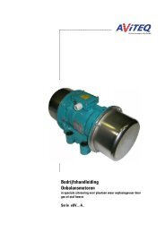
5.2.1 Single Drive<br />
For single drives, the direction of rotation of the unbalance motor may be chosen freely.<br />
5.2.2 Double Drive<br />
If the unbalance motors are installed in pairs, the direction of rotation has to be set<br />
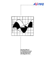
depending on the desired oscillation movement. For linear oscillations, the unbalance<br />
motors must rotate in opposite directions. For spiral oscillations (helical oscillations),<br />
the unbalance motors must rotate in the same direction.<br />
Briefly (max. 2 seconds) switch on the unbalance motors to check the direction of<br />
rotation. For this purpose, remove the upper protective hood at each unbalance<br />
motor.<br />
ATTENTION!<br />
Damage of the unbalance motor and the risk of injuries with the types UVE 7,7Y-A1;<br />
UVE 7X-A1 and UVE 3W-A1 possible! With these types the protective hoods are part<br />
of the bearing shield construction and are used for fixing the bearing shields.<br />
Therefore only the upper protective hood is to be removed to avoid the motor shaft<br />
from getting loose!<br />
We recommend to fix the bearing shield temporarily after removing the protective<br />
hood by screwing in the appropriate fixing screws. Please mount the protective hood<br />
again after checking the sense of rotation.<br />
To verify the direction of rotation, it is sufficient to switch the motor on and<br />
immediately off again.<br />
DANGER!<br />
Touching the rotating centrifugal weights may be perilous and lead to serious injuries!<br />
Ensure that you and others stay far enough away and that no objects can intrude<br />
into the area near the centrifugal weights!<br />
Changing the direction of rotation<br />
<br />
If the direction of rotation on one of the motors is incorrect, swap two or<br />
three phases on the connexion cable leading to the unbalance motor.<br />
...........................................................................................................................................................................................................................................................................................................................................................................................<br />
36 / 48