Operating Manual Unbalance Motors - AViTEQ Triltechniek
Operating Manual Unbalance Motors - AViTEQ Triltechniek
Operating Manual Unbalance Motors - AViTEQ Triltechniek

You also want an ePaper? Increase the reach of your titles
YUMPU automatically turns print PDFs into web optimized ePapers that Google loves.
...........................................................................................................................................................................................................................................................................................................................................................................................................<br />
To avoid abrasion on the cables, the wiring should be fixed except for the last 0.5 m<br />
leading to the unbalance motor. This part of the cables must sag freely such that the<br />
vibration movement does not cause tensile stresses on the cables.<br />
DANGER!<br />
Short circuits and electric shock may result if insulation is damaged by rubbing!<br />
Connecting cables must never come in contact with vibrating parts – otherwise, the<br />
insulation may get damaged. Run the cables in a way that excludes this danger!<br />
NOTE<br />
If the connexion cable goes into resonance during operation, which leads to<br />
excessive swinging of the cable, altering the length changes the resonance and<br />
makes the cable to move normal. Shorten or extend the cable in this case!<br />
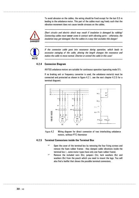
4.2.4 Connexion Diagram<br />
<strong>AViTEQ</strong> unbalance motors are suitable for continuous operation (operating mode S1).<br />
If no braking unit or frequency converter is used, the unbalance motor(s) must be<br />
connected and protected as shown in figure 4.2 (…see the next chapter 4.2.5 for a<br />
terminal diagram).<br />
VIB-SE1-803S<br />
Figure 4.2<br />
Wiring diagram for direct connexion of two interlocking unbalance<br />
motors, without PTC thermistor<br />
4.2.5 Terminal Connexions inside the Terminal Box<br />
<br />
<br />
Open the cover of the terminal box by removing the four fixing screws and<br />
remove the foam rubber frames - they dampen cable vibrations inside the<br />
terminal box (…some motor types have only one foam rubber frame).<br />
Remove the included nuts (6x), jumpers (3x), lock washers (6x) and<br />
washers (6x) from the pouch which you need to mount the lugs. You will<br />
also find a leaflet that shows the possible terminal connexions.<br />
...........................................................................................................................................................................................................................................................................................................................................................................................<br />
30 / 48