Operating Manual Unbalance Motors - AViTEQ Triltechniek
Operating Manual Unbalance Motors - AViTEQ Triltechniek
Operating Manual Unbalance Motors - AViTEQ Triltechniek

You also want an ePaper? Increase the reach of your titles
YUMPU automatically turns print PDFs into web optimized ePapers that Google loves.
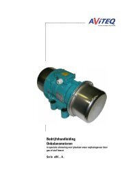
<strong>Operating</strong> <strong>Manual</strong> for <strong>AViTEQ</strong> <strong>Unbalance</strong> <strong>Motors</strong>, Series UV...-A_<br />
...........................................................................................................................................................................................................................................................................................................................................................................................................<br />
The terminal allocation depends on the motor type and whether or not the PTC<br />
thermistor is to be connected. There is also the choice between star-connexion (high<br />
voltage) or delta-connexion (low voltage).<br />
Look up the appropriate connexion designator in the “Connect” line of the motor's<br />
type label. If this information is missing, use the data in the accompanying special<br />
data sheet for the circuit.<br />
NOTE<br />
The leading-out wires are always wired in the direction of the rotating field. This<br />
simplifies cable connexion for a given direction of rotation.<br />
All unbalance motors must be operated by using all three phases (…except single<br />
phase drives). A two-phase operation is not allowed!<br />
<br />
Select the correct scheme and connect according to the appropriate<br />
diagram. Always use ring-shaped lugs for connecting the wires.<br />
Scheme 2A<br />
delta-connexion<br />
(low voltage)<br />
star-connexion<br />
(high voltage)<br />
mains supply<br />
mains supply<br />
delta-connexion<br />
(low voltage)<br />
star-connexion<br />
(high voltage)<br />
Scheme 5A<br />
mains supply &<br />
PTC thermistor<br />
mains supply &<br />
PTC thermistor<br />
Figure 4.3<br />
Connexion schemes for wiring in the terminal box (..if included,<br />
observe the special data sheet which may accompany the motor!)<br />
...........................................................................................................................................................................................................................................................................................................................................................................................<br />
© 2009 <strong>AViTEQ</strong> Vibrationstechnik GmbH Version 04/2009 31 / 48