July 2013 - Wright-Patterson Air Force Base
July 2013 - Wright-Patterson Air Force Base
July 2013 - Wright-Patterson Air Force Base

You also want an ePaper? Increase the reach of your titles
YUMPU automatically turns print PDFs into web optimized ePapers that Google loves.
DISTRIBUTION A. Approved for public release; distribution unlimited. (WP Public Affairs Case Number 88ABW-<strong>2013</strong>-3177)<br />
Director’s Comments<br />
I’m sure I’m not alone in feeling that this<br />
is the longest fiscal year of my <strong>Air</strong> <strong>Force</strong><br />
career. Budget uncertainty has certainly<br />
sharpened our planning skills and helped<br />
us focus on the core functions of our<br />
business. <strong>Air</strong> <strong>Force</strong> civil servants have<br />
been notified that furloughs, if enacted,<br />
will start the second week of <strong>July</strong>. We<br />
will follow AFLCMC guidance to focus<br />
furlough days on Fridays. If this comes<br />
to pass, it will affect the staff’s productivity.<br />
We will do everything possible to<br />
overcome the 20 percent reduction in<br />
collective man-hours by reducing<br />
extraneous meetings, projects, and<br />
distractors so the staff stays focused on<br />
our number one priority, customer<br />
support for field issues. Give us as much<br />
notice as possible, be patient, and follow<br />
up if you don’t hear from us.<br />
Across the spectrum of operations, the<br />
<strong>Air</strong> <strong>Force</strong> is looking for ways to reduce<br />
costs and directing the MAJCOMs to fall<br />
in line. Inspection oversight is a<br />
high-interest area. Changes to Inspector<br />
General programs are looming that will<br />
affect how PMELs are assessed in the<br />
future. Chief McKinnon is providing<br />
further details.<br />
Thus far, we have weathered the<br />
Sequestration budget cuts with most<br />
requirements funded. Our AFPSL<br />
contractor enacted austerity measures<br />
that stretched the budget, and we<br />
appreciate efforts of our MAJCOM<br />
MFMs and Node Managers to scrutinize<br />
every N49/59/64 calibration item. We<br />
are managing our shortage in CAM<br />
equipment funding by deferring what we<br />
can to future years. Help us by taking a<br />
<strong>July</strong> <strong>2013</strong><br />
Volume 33, Issue No. 3<br />
AFMETCAL<br />
NEWSLETTER<br />
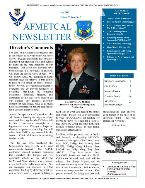
Colonel Victoria H. Reed<br />
Director, <strong>Air</strong> <strong>Force</strong> Metrology and<br />
Calibration<br />
hard look at what you need in the future<br />
and when. Please join us in advocating<br />
to your MAJCOM/A4s for funding for<br />
MFMs to travel to Heath for a face-toface<br />
Advisory Group meeting in the fall,<br />
because working issues in that forum<br />
maximizes effectiveness.<br />
I will end with a personal word of thanks<br />
and farewell to departing MAJCOM<br />
Functional Managers: Chief John Leary<br />
from ACC, SMSgt Rod Hartwig from<br />
USAFE, SMSgt Greg Johnson from<br />
PACAF and MSgt Greg Earp from<br />
AFGSC. They have served their<br />
MAJCOM leadership and the PMEL<br />
Calibration Network well and will be<br />
missed. But change is good, and we<br />
welcome the new eyes and fresh perspective<br />
of new Functionals. And as always,<br />
thanks to every member of our 1800-<br />
person network for doing your job with<br />
AIR FORCE<br />
METROLOGY<br />
Special Points of Interest:<br />
Process Review Culture (pg. 5)<br />
PPC3 Changed from N40 to<br />
Cal & Return (pg. 7)<br />
ADC-2500 Inspection<br />
Procedure (pg. 9)<br />
Releasing Hidden Value<br />
Streams in PMEL (pg. 13)<br />
NSCS Runtime Errors (pg. 14)<br />
Gage Blocks 101 (pg. 16)<br />
Importance of Calibrating<br />
Spectral Purity (pg. 17)<br />
Fittings for New Vacuum Cal<br />
System pg. (22)<br />
<br />
Inside This Issue:<br />
Director’s Comments 1<br />
Chief’s Corner 3<br />
News and Notes 5<br />
From the Bench 14<br />
AFMETCAL<br />
Personnel Changes<br />
Coming Events:<br />
23<br />
professionalism and cheerful<br />
good humor in the face of an<br />
uncertain future. See you<br />
around the Network!<br />
Colonel Reed<br />
AFMETCAL Advisory Group/<br />
PAMS-CCB/PIWG/RNI<br />
Meetings<br />
(5-6 November <strong>2013</strong>)<br />
DISTRIBUTION A. Approved for public release; distribution unlimited. (WP Public Affairs Case Number 88ABW-<strong>2013</strong>-3177)
Page 2<br />
AFMETCAL NEWSLETTER<br />
<strong>July</strong> <strong>2013</strong><br />
Volume 33, Issue No. 3<br />
The views and<br />
opinions expressed<br />
herein, unless<br />
otherwise specifically<br />
indicated, are those of<br />
the individual author.<br />
They do not purport to<br />
express the views of<br />
the U.S. Government,<br />
the Department of<br />
Defense, Department<br />
of the <strong>Air</strong> <strong>Force</strong> or<br />
HQ AFMC.<br />
Disclosure & Editorial Policy<br />
Disclosure: The <strong>Air</strong> <strong>Force</strong> Metrology and<br />
Calibration (AFMETCAL) Program Newsletter<br />
is published on a triannual basis (Mar,<br />
Jul, Nov) by the AFMETCAL Division<br />
(AFLCMC/WNM), Plans & Analysis Section<br />
(AFLCMC/WNMRX), 813 Irving-Wick<br />
Drive W, Heath, Ohio 43056-1199.<br />
The views and opinions expressed herein,<br />
unless otherwise specifically indicated, are<br />
those of the individual author. They do not<br />
purport to express the views of the U.S.<br />
Government, the Department of Defense,<br />
Department of the <strong>Air</strong> <strong>Force</strong> or HQ AFMC.<br />
Information contained in the AFMETCAL<br />
Newsletter is for informational purposes and<br />
is not directive in nature. Photographs are<br />
the property of the United States <strong>Air</strong> <strong>Force</strong><br />
unless otherwise stated.<br />
The appearance of hyperlinks does not constitute<br />
endorsement by the U.S. <strong>Air</strong> <strong>Force</strong> of<br />
the respective web site or the information,<br />
products or services contained therein. The<br />
U.S. <strong>Air</strong> <strong>Force</strong> does not exercise any editorial<br />
control over the information found at those<br />
locations.<br />
Editorial Policy Statement: The AF-<br />
METCAL Quarterly Newsletter is the AF-<br />
METCAL Director’s forum to share insights<br />
into policy and emerging trends, personnel<br />
news, technical and other information of interest<br />
to the <strong>Air</strong> <strong>Force</strong> metrology community<br />
at large. Newsletter articles cover many topics:<br />
technical issues; clarifications of policies/procedures;<br />
process improvements; and<br />
items of general interest about <strong>Air</strong> <strong>Force</strong> metrology<br />
community members.<br />
Submissions: We encourage readers to submit<br />
articles for the following categories:<br />
From the Bench (technical), About People<br />
(field personnel news), News & Notes<br />
(general information). Submissions should<br />
be in Microsoft Word, Times New Roman 12<br />
font, accompanied whenever possible by<br />
digital photos in JPEG format. Native photo<br />
file sizes less than 2MB per image are preferred.<br />
Photos must be accompanied with<br />
caption information which fully identifies all<br />
individuals depicted, including rank, title<br />
or office, and event. Note that all text and<br />
photo submissions are subject to editing<br />
for content, cropping and/or size. All submissions<br />
that are technical in nature are<br />
reviewed by the AFMETCAL Engineering<br />
Branch (AFLCMC/WNME) for accuracy<br />
and appropriateness. Publication of any<br />
submission, regardless of subject matter,<br />
will be approved by the AFMETCAL Division<br />
and submission does not guarantee<br />
publication. All submissions are reviewed<br />
for compliance with Privacy Act, FDO,<br />
STINFO, OPSEC and other information<br />
security requirements as applicable.<br />
How to Make a Submission: The AF-<br />
METCAL Newsletter editor transmits<br />
quarterly calls for inputs through the<br />
PMEL MAJCOM Functional Managers<br />
and other significant metrology program<br />
POCs to the respective PMEL managers<br />
and/or program functional offices. Normal<br />
submissions are in response to these data<br />
calls. Authors should submit their article<br />
inputs via e-mail through their respective<br />
chain of command to the AFMETCAL<br />
Newsletter editor. Authors may submit<br />
inputs out of cycle, but should use the<br />
same channels for those submissions.<br />
Deadline for submissions is the 15th of the<br />
month prior to the scheduled quarterly<br />
newsletter publication (publication months<br />
are March, <strong>July</strong> and November). Do not<br />
submit copyrighted material.<br />
Director, <strong>Air</strong> <strong>Force</strong> Metrology &<br />
Calibration<br />
Colonel Victoria H. Reed<br />
Editor:<br />
Bob Nappier<br />
Assistant Editor:<br />
Lee Wood
Page 3<br />
Chief’s Corner<br />
AFMETCAL NEWSLETTER<br />
<strong>July</strong> <strong>2013</strong><br />
Volume 33, Issue No. 3<br />
The Six Degrees of PMEL Change<br />
Wow, the AFMETCAL whirlwind tour continues. The past four<br />
months were fast and furious, driven by a multitude of concurrent<br />
budget constraints and transformation initiatives. While challenging to<br />
say the least, it also offered an incredible and rare opportunity to affect<br />
positive change on our program. One thing for sure, we are all<br />
connected in one way or the other by the upcoming changes to the<br />
PMEL landscape. I’ll call it the six degrees of PMEL change. Changes<br />
ranging from Repair Network Integration implementation; the soon to<br />
be vetted/released 2P manpower standard; significant changes to both<br />
AFI 21-101 and TO 00-20-14; results of sequestration on our day-today<br />
budgets/operations/civilian furloughs; and last but not least, significant<br />
changes to the <strong>Air</strong> <strong>Force</strong> Inspection System (AFIS) impacting the<br />
AFMETCAL Certification Team and ultimately, you. Since announcement<br />
of the <strong>Air</strong> <strong>Force</strong>’s “White Space” initiative and changes to the<br />
AFIS, the AFMETCAL PMEL Assessment and Certification Program<br />
experienced a multitude of modifications. Folks, put on your seat belt,<br />
because there’s more on the way. Tomorrow’s sight picture of the<br />
AFMETCAL Certification Team will be significantly different from<br />
today’s and that’s my focus; to provide some vision and insight on<br />
where we are heading regarding AFIS. But for some perspective, let’s<br />
cover a little of where we were and are.<br />
Chief Master Sergeant<br />
Martin McKinnon<br />
Chief, Laboratory Certification Branch<br />
Prior to the White Space initiative, AFMETCAL was the process owner for all assessment scheduling, criteria, notification,<br />
duration, result determination, certification, and finally reporting. We inspected for both capability/performance<br />
and compliance. Subsequently, the “White Space” and the initial phase of AFIS changes came down the pipe. A few of<br />
you have already experienced the results of this phase: Consolidated Unit Inspections (CUI)/(Tier 0, 1, 2), the tool used<br />
by the IG to combine required/desired functional inspections into 1- or 2- week inspection blocks. CUIs would include<br />
teams from LCAP, NSI, HSI, ORI, and/or AFMETCAL to name a few. While we aligned under the CUI concept, not<br />
much really changed regarding the AFMETCAL Certification process.<br />
The primary impact of the CUI concept to our AFMETCAL Assessment and Certification Program drove changes to<br />
when and how we perform our on-site assessments. Now, 95% of the assessment schedule is synchronized with the IG<br />
schedule. Notification flows through the IG to your wing/base Gatekeeper and not directly from AFMETCAL.<br />
NOTE: I need to foot stomp this one folks. AFMETCAL Certification Team members are considered trusted agents and<br />
we are not authorized to provide scheduled assessment dates. Please refrain from calling the team to request our on-site<br />
dates. We are not authorized to release this information to you until after official notification is released so hold fast for<br />
your official notification; it can be as short as 45 days depending on your MAJCOM’s notification policy.<br />
The term “synchronized” does a good job in describing how we are currently aligned with the IG’s schedule. We go<br />
when they go but we still currently operate somewhat independent of the IG. We have our own reports and in/out-briefs,<br />
we make our own travel arrangements and usually don’t wear the IG badge. Some other significant changes brought<br />
about by this phase included: on-site footprint was reduced to 5 duty-days, reduced/altered the Quality Program and<br />
Management System interview process, and we reduced assessment of some preliminary calibration steps.<br />
Finally, the meat of my message: Where are we heading? To frame this, I think I need to provide some key SAF/IGI<br />
changes that are driving this end state. There will be two major components to the new AFIS. First, the Wing<br />
Commander’s Inspection Program (CCIP) will be responsible for all compliance inspections at that wing. CCIP is the<br />
foundation of the AFIS and has two primary components: a wing inspection program and a self-assessment inspection<br />
(Continued on page 4)
Page 4<br />
AFMETCAL NEWSLETTER<br />
<strong>July</strong> <strong>2013</strong><br />
Volume 33, Issue No. 3<br />
Chief’s Corner (continued)<br />
(Continued from page 3)<br />
program. The wing IG, with support from subject-matter experts, will execute the wing inspection program to inspect<br />
Groups, Squadrons and other organizations below the Wing level. The self-assessment program, enabled by the<br />
Management Internal Control Toolset (MICT), will capture and report unit performance data to the chain of command<br />
and appropriate staffs.<br />
The second key element of the new AFIS is the Unit Effectiveness Inspection (UEI). The UEI is a significant change in<br />
focus for MAJCOM IGs. The UEI validates and verifies a wing CC’s inspection program and offers the MAJCOM CC<br />
an independent assessment of the unit’s discipline, effectiveness, efficiency and readiness. The UEI includes a 24-30<br />
month continual inspection cycle for Active-Duty and AFRC units/48-60 months for ANG and on-site IG visits to<br />
conduct focus groups, interviews, task evaluations, audits and observations. No later than 1 Oct 14, AFMETCAL will<br />
be fully integrated into the IG UEI. With this, you should expect the following changes to the current AFMETCAL<br />
assessments:<br />
1) AFMETCAL Assessment Team will inspect each PMEL during their UEI. Not all wing/base units or organizations<br />
will be assessed by the IG, but due to PMEL’s inherent risk associated with a break in safety, accuracy, reliability or<br />
traceability of measurements, PMEL will most assuredly be evaluated.<br />
2) PMEL assessment will consist of only performance based observations/task evaluations. We will no longer look at<br />
the facility, environment, Management System, or Proficiency Testing. We will focus only on the Measurement<br />
Capability Assessment and Quality Program Effectiveness pieces of the current assessment program. All the compliance<br />
based items will be passed on to the CCIP and MICT checklists.<br />
3) AFMETCAL Assessment Team members will become official IG Inspectors, but will no longer certify the PMEL.<br />
The MAJCOM IGs do not certify and we will be augmenting the MAJCOM IGs. Additionally, expect only IG in/outbriefs<br />
and reports. The AFMETCAL in/out-briefs and reports will no longer be necessary.<br />
4) Results will not be pass/fail. The IG/AFMETCAL will use elements of the 5-tier rating system.<br />
5) If significant problems exist, we won’t be dealing with certification withhold, we will be dealing with Corrective<br />
Action Plans (still worked through MAJCOM Functionals) with revisits still a viable option.<br />
While these changes are necessary in order to comply with new Secretary of the <strong>Air</strong> <strong>Force</strong> requirements and directives,<br />
they also come with the hope we can streamline the oversight process and place process ownership/compliance<br />
validation in the proper hands. The manpower utilized to “paint the grass” or ramp up for another inspection should now<br />
be utilized to strengthen day-to-day compliance. The wave of change is upon us and it’s time we embrace it and make<br />
the best of it. The delivery mechanism may have changed, but we will safeguard the ability to evaluate safe, accurate,<br />
reliable and traceable measurements and that’s what it’s all about. The six degrees of change will not impact the<br />
fundamental and underlying principle all of us are committed to – every step; every item; every day!<br />
MARTIN B. MCKINNON, CMSgt, USAF<br />
Chief, Laboratory Certification Branch/2P Career Field Manager<br />
AF Metrology and Calibration Division, AFPEO Agile Combat Support
Page 5<br />
AFMETCAL NEWSLETTER<br />
<strong>July</strong> <strong>2013</strong><br />
Volume 33, Issue No. 3<br />
News and Notes<br />
A Process Review Culture...<br />
Recently, I completed a lengthy analysis of the assessed PMEL quality trends from 2007-2012. This analysis involved<br />
the review of more than 250 assessment reports and over 60,000 data points. What did I find? Short story…the Process<br />
Review is KING! Below is the semi-longer story.<br />
To preface the results of this analysis, I would like to overview the value a process review (PR) and quality review (QR)<br />
provide to a PMEL. A PR provides a microscopic view into a specified area(s) of a process. This may highlight potential<br />
errors that could be passed on to effect end of line product quality. The knowledge gained from a PR is preventative<br />
and may identify areas of improvement. The actions resulting from process nonconformities are proactive in nature and<br />
should be used to continuously improve the production system. A QR is a complete review of an item at the end of a<br />
process chain within a production system. The knowledge gained from a QR is minimal as more data/information is<br />
usually required to determine cause. The actions resulting from quality nonconformities are reactive and require a PR to<br />
accurately determine how the nonconformity was caused. What does this overview have to do with the analysis?<br />
When looking at the data from 2007 to 2012, a clear pattern developed with respect to lab assessment pass ratings.<br />
Further investigation revealed that the culture of our PMELs was starting to change. In 2007, TO 00-20-14 (20071030)<br />
changed to include this statement, “All K-stamp holders shall participate in at least two PRs every 12 months.” As<br />
PMELs changed the way quality programs implemented this new requirement, the data received from the assessments<br />
began to show positive trends in assessment results. One way to highlight these trends was the creation of the PR/QR<br />
Ratio. The PR/QR Ratio is generated by dividing a lab’s PR count by QR count within a specified period. Example – If<br />
a lab has a PR/QR Ratio of 0.2, then the lab performs 1 PR for every 5 QRs.<br />
As seen in Figure 1, from 2007 to 2012, there is an increase in the average PR/QR Ratio per year for labs assessed.<br />
Figure 2 goes a step further and breaks out the average PR/QR Ratio for successful labs and unsuccessful labs. If this<br />
information doesn’t completely sell the value of PRs, Figure 3 (next page) may help.<br />
(Continued on page 6)<br />
Figure 1 - PR_QR Ratio for all assessments from 2007-2012<br />
Figure 2 - PR_QR Ratio Pass/Fail Comparisons
Page 6<br />
AFMETCAL NEWSLETTER<br />
<strong>July</strong> <strong>2013</strong><br />
Volume 33, Issue No. 3<br />
News and Notes (continued)<br />
(Continued from page 5)<br />
A Process Review Culture…(continued)<br />
Figure 3<br />
PR/QR Probability<br />
Plot<br />
Figure 3 is a probability plot. A probability plot is typically used for estimation. However, in this manner, it is used as a<br />
qualitative tool providing a comparison from successful labs ( ) to unsuccessful labs ( ). With this in mind,<br />
the X axis is the PR/QR Ratio and Y Axis is the probability in percent. As we move up the Y axis to 50%, the two data<br />
populations cross the X axis at 0.25 PR/QR Ratio. This figure starts to paint a great picture on the effects PRs have on<br />
the lab measurement capability assessment (MCA) success at around the 97.5% mark on the Y axis. As can be seen,<br />
there is not a lab with a 0.45 PR/QR Ratio or higher that has failed an assessment to date. Additionally, the labs with<br />
greater success have higher PR/QR Ratios than most of the population of assessed labs.<br />
I know some readers are questioning how successful labs with a 0.2 PR/QR Ratio can pass while some unsuccessful labs<br />
have equal to or higher PR/QR Ratios. The answer to this question comes down to talent and hard work. After reading<br />
more than 250 assessment reports, I found the sole factor that determined a successful lab from an unsuccessful lab was<br />
the results of the MCA. Now some managers are nodding “Yes” as it has been stated over the years that the more PRs<br />
performed will most likely yield greater benefits to the calibration process. This data validates that a PR centered quality<br />
program may garner more successful assessment results and more importantly, increased end of line product quality.<br />
In conclusion, I would like to highlight some of the main takeaways from this analysis. First, the more process reviews a<br />
lab performs, the better chance it has to pass the MCA portion of an assessment and most importantly, the better the end<br />
of line product quality. Second, the difference between successful and unsuccessful labs comes down to the results of<br />
the MCA. The use of the PR is extremely valuable when this statement is taken to heart. As a technician, supervisor, or<br />
manager, you do not want to be blindsided with process issues that could have been caught during a PR. Lastly, if there<br />
is a technician, process, or capability that management wants to look harder at, use targeted PRs. Do not increase QR<br />
rates in hopes to identify QNCs that will ultimately generate a PR. Bottom line, dollar for dollar, the PR will make you<br />
more money in the long run.<br />
If you have any questions or comments about the analysis provided, please do not hesitate to contact me at<br />
charles.holman@afmetcal.af.mil or DSN 312-366-5096.<br />
MSgt Charles Holman<br />
Laboratory Certification Branch<br />
AFLCMC/WNMQ
Page 7<br />
AFMETCAL NEWSLETTER<br />
<strong>July</strong> <strong>2013</strong><br />
Volume 33, Issue No. 3<br />
News and Notes (continued)<br />
PPC3 Low Pressure Secondary Standard Changed<br />
from N40 to Cal & Return<br />
The PPC3 (i.e. PPC3-200K BG15KP (W) DVU, WUC: WXSB0) was purchased by AFMETCAL from FY05 to FY08<br />
as a low pressure exchange standard. The AFPSL recently identified that the PPC3 exchange pool assets are too low to<br />
continue this effort due to many units being damaged. Because of spending cuts, AFMETCAL is unable to repair these<br />
units and therefore will be changing the PPC3 listing from Exchange to Cal & Return. Accordingly, damaged units will<br />
be repaired at the local PMEL level. These items have been in the field for many years and shipped from every PMEL to<br />
the AFPSL for calibration. While a few of the units were damaged by shipping, most of the units’ transducers have gone<br />
bad due to over-pressurizing and incorrect set up or use.<br />
Shipping issues were mainly attributed to excessive vibration which caused the loosening of the three screws that fasten<br />
the transducer bracket to a solid steel block inside the unit, in turn causing the transducer to be tossed around during<br />
shipping and ultimately being damaged.<br />
Picture of a unit with a damaged transducer during shipping due to a loose bracket.<br />
Over-pressurization can be caused by one of the following scenarios:<br />
<br />
Technician sets a pressure without the proper pressure or vacuum input sources applied (disconnected or turned off)<br />
to the PPC3. When realized, the technician tries to correct the problem without first venting the PPC3. This can over<br />
-range the transducer.<br />
(Continued on page 8)
Page 8<br />
AFMETCAL NEWSLETTER<br />
<strong>July</strong> <strong>2013</strong><br />
Volume 33, Issue No. 3<br />
News and Notes (continued)<br />
(Continued from page 7)<br />
<br />
<br />
PPC3 Low Pressure Secondary Standard Changed<br />
from N40 to Cal & Return (continued)<br />
Technician sets a pressure and then realizes there is a leak in the system. The technician tries to fix the leak without<br />
first venting the PPC3. This can over-range the transducer.<br />
The PPC3 is used as a monitor, and an external controller can easily over-pressurize the PPC3 and damage the<br />
transducer.<br />
To ensure the PPC3 does not get over-pressurized, warning statements will be added to the calibration procedures in<br />
which the standard is used. There are currently 21 calibration Technical Orders which utilize this item and they will be<br />
the ones addressed with these statements. The statements will be as follows:<br />
<br />
<br />
<br />
<br />
Ensure all proper connections are connected and opened before operating the PPC3.<br />
Always vent the PPC3 before fixing any leaks or calibration set-up.<br />
Never connect a pressure supply greater than 20% over the maximum control pressure of the PPC3. Only connect<br />
the pressure supply to the SUPPLY port.<br />
The PPC3 is a Pneumatic Pressure Controller. Do not use it as an indicator. Do not apply pressure to both the TI and<br />
the PPC3 Controller at the same time. If not strictly observed, could result in damage to, or destruction of,<br />
equipment or loss of mission effectiveness.<br />
George Ephrem<br />
Mechanical Engineering Section<br />
AFLCMC/WNMEM
Page 9<br />
AFMETCAL NEWSLETTER<br />
<strong>July</strong> <strong>2013</strong><br />
Volume 33, Issue No. 3<br />
News and Notes (continued)<br />
ADC-2500 Inspection Procedure<br />
In the course of providing calibration support for an ADC-2500 <strong>Air</strong> Data Calibration Test Set, we noted what appeared<br />
to be shipping damage to the unit. We could hear a “rattling noise” when we moved the item within our PMEL—and<br />
that’s never a good thing.<br />
An inspection of the item revealed that the Power Supply and a Filter had become unsecure and damaged several connectors<br />
on a circuit board. We had noted a loose Power Supply assembly in another unit in the past—but simply reasoned<br />
it was an “isolated incident”—after all, we had never noted a similar problem before. However, now that we’ve<br />
identified another unit with the same issue, we reasoned that there might be a systemic problem with the assembly of<br />
the unit.<br />
Flipping the Power Supply assembly over, we noticed nothing out of the ordinary. A review of the maintenance data<br />
on the item revealed no specifications for torque of the screws holding the assembly to the chassis. However, there<br />
was no Loctite sealant or adhesive on the screws in question—this would certainly aid in keeping the unit secure.<br />
Therefore, we put together this small presentation to help you prepare your unit for shipment when calibration is necessary.<br />
If you’ll follow the enclosed instructions for each of your units prior to shipment, you can significantly increase the<br />
chances that your unit will arrive without damage and ready for us to calibrate.<br />
After the initial application of Loctite (or some other sealant/adhesive) to the screws in question, any future actions<br />
should be limited to a quick internal inspection prior to shipment—simply make sure the Power Supply and Filter<br />
Capacitor are securely attached to the chassis.<br />
Please direct any questions to our Production Supervisor, Mr. Steve Gordon or our Technical Expert in this area, Mr.<br />
Joshua Strickler at DSN 226-7011.<br />
Steve Gordon/RAF Feltwell PMEL<br />
Remove ADC-2500 top cover and locate Power Supply Assembly and Filter Capacitor<br />
Power<br />
Supply<br />
Filter<br />
Capacitor<br />
Continued on page 12
Page 10<br />
AFMETCAL NEWSLETTER<br />
<strong>July</strong> <strong>2013</strong><br />
Volume 33, Issue No. 3<br />
News and Notes (continued)<br />
Continued from page 11<br />
ADC-2500 Inspection Procedure (continued)<br />
Remove the six screws securing the Power Supply Mounting Plate to the Chassis<br />
Continued on page 13
Page 11<br />
AFMETCAL NEWSLETTER<br />
<strong>July</strong> <strong>2013</strong><br />
Volume 33, Issue No. 3<br />
News and Notes (continued)<br />
ADC-2500 Inspection Procedure (continued)<br />
Continued from page 12<br />
Rotate the Power Supply Assembly Mounting Plate so you can see the bottom surface<br />
Verify the four screws attaching the Power Supply Assembly to the plate are present and secure. It not already treated, loosen each<br />
screw in turn and apply Loctite or a similar adhesive to the screw. Then tighten each screw. Carefully re-position the mounting plate<br />
and secure to Chassis with the six screws previously removed.<br />
Power Supply Assembly attaching screws<br />
Continued on page 14
Page 12<br />
AFMETCAL NEWSLETTER<br />
<strong>July</strong> <strong>2013</strong><br />
Volume 33, Issue No. 3<br />
News and Notes (continued)<br />
Continued from page 13<br />
ADC-2500 Inspection Procedure (continued)<br />
Verify the Filter Capacitor is tightly secured to the Chassis with screws on each side<br />
Replace Cover on ADC-2500. Ship at your convenience!!
Page 13<br />
AFMETCAL NEWSLETTER<br />
<strong>July</strong> <strong>2013</strong><br />
Volume 33, Issue No. 3<br />
News and Notes (continued)<br />
Releasing Hidden Value Streams in the PMEL: A Shift in Perspective<br />
How invisible is your PMEL operation to your customer? For the<br />
PMEL, this question may bear significantly upon your customer’s<br />
satisfaction level. Finding value within an inspection activity can be an<br />
elusive endeavor, because a PMEL has a counterintuitive value-add<br />
structure inherent to its activities. Consider this: If the PMEL brings in a<br />
piece of equipment, tests the equipment, and the equipment meets its<br />
specification, the cost of calibration is sunk. The PMEL process<br />
contains very little value-add activity, beyond regulatory compliance,<br />
when product is conforming upon receipt. Historically, this is the<br />
paradigm in the <strong>Air</strong> <strong>Force</strong> laboratory, but a shift in perspective may<br />
unleash the potential for the PMEL to operate under a new paradigm<br />
that unleashes the hidden value streams within the PMEL calibration<br />
process.<br />
First, consider the implications of using automation beyond a simplistic<br />
assembly-line type increase in productivity. What if you went to the<br />
doctor and the only record your doctor kept was “Healthy” or “Sick”?<br />
How valuable are these records? These types of records are equivocal to<br />
the level of insight gained through most traditional calibration processes<br />
in use to date. The detailed records of a piece of TMDE’s health<br />
Mr. Michael Meggs<br />
coupled with the ease with which a computer amasses these records<br />
makes automation an integral development in the PMEL community. When faced with the decision between performing<br />
an automated or manual calibration process, the automated procedure should automatically garner preference solely on<br />
the basis of its data mining capabilities. These capabilities translate into reduced customer visibility by allowing the<br />
PMEL to isolate peculiar calibration conditions, such as measurements that are biased but that are consistently in tolerance<br />
over time. Without the capability to see the value of the measurement over time, the likelihood of an unnecessary<br />
adjustment will increase, thus resulting in increased turnaround times. Also, the PMEL will be able to predict calibration<br />
failure times by viewing measurements that are in tolerance across calibration intervals but that are drifting towards<br />
specification limits and plan accordingly through the production control process. Automation turns the sunk cost of<br />
inspection into an asset, namely the record of the TMDE’s quantitative condition rather than its qualitative condition,<br />
and this will unlock additional revenue streams over time as the laboratory explores new ways to interpret the data<br />
collected through automated calibration.<br />
Second, consider the value of your metrics from the perspective of the customer. PMEL technicians feel the pain of<br />
backlog, but do customers feel this same pain? Consider this: If you have a backlog of one million widgets with the<br />
capability to calibrate one million widgets with a one day turn-around, will your customers be dissatisfied? While the<br />
scenario is hyperbolic, its intent is to show the importance of production control’s duty of balancing inputs and outputs.<br />
With the assumption of a zero-day backlog at the outset, a perfectly balanced input and output from the PMEL results in<br />
no residual. One can see how the classical paradigm of more-is-better for production control does not fit the PMEL<br />
invisibility paradigm; rather, balanced-is-better is the name of the new game. The PMEL should strive to match its<br />
average daily output to its average daily input, else it becomes a bottleneck operation, either pushing unnecessary<br />
product to the customer or pulling unnecessary product into the lab. The time required for calibration must receive due<br />
consideration, and once more computer information systems prove invaluable in determining mean calibration time and<br />
the standard deviation of that time, in order to quantify the most economical point in time to bring the equipment into<br />
the laboratory. Operations management principles can be rigorously applied to quantify lead times with a fair amount of<br />
accuracy.<br />
(Continued on page 14)
Page 14<br />
AFMETCAL NEWSLETTER<br />
<strong>July</strong> <strong>2013</strong><br />
Volume 33, Issue No. 3<br />
News and Notes (continued)<br />
Releasing Hidden Value Streams in the PMEL: A Shift in Perspective<br />
(continued)<br />
(Continued from page 13)<br />
Finally, consider the impact of unleveled production extrapolated over time on the inventories of your customers. Backlog<br />
goes up in the PMEL, and the customer compensates with new inventory. The new inventory creates higher workload<br />
on the PMEL, and turnaround times increase further, ad nauseam, creating a flywheel effect on the calibration<br />
equipment inventory. How well do you know your customer’s requirements for TMDE? If true demand for quantitative<br />
measurement triggers the purchase of new TMDE, the PMEL should operate as the vanguard for the new acquisition,<br />
meaning the attrition of obsolete equipment that is being replaced by the new standard should be coordinated through<br />
the PMEL. The PMEL must also work to standardize TMDE across the maintenance complex, striving to provide<br />
TMDE with evidence of reliability through longer calibration intervals to customers with identical requirements. How<br />
many different brands of 200 inch pound torque wrenches with a 4% uncertainty are supported by your PMEL? One<br />
could argue that any answer other than one is not optimal, because standardization decreases training hours, changeover<br />
times, and ultimately turn-around time.<br />
Effectively using automation, production control, and standardization will allow the PMEL to increase customer<br />
satisfaction by decreasing the amount of time customer equipment spends in PMEL possession. This paradigm shift is<br />
not without obstacles, and customers must be convinced that letting go of excess safety stock will work to their<br />
advantage, so know what you do and why you do it.<br />
Michael Meggs<br />
Columbus AFB, MS<br />
From The Bench<br />
Noise Source Calibration System “Runtime Errors”<br />
Recently, during a capability assessment, we ran into an issue with our TA110000-622.<br />
While attempting to perform the system “Self Test”, we kept receiving either a<br />
“RUNTIME ERROR 9” or “RUNTIME ERROR 13”. After talking to other colleagues, I<br />
received mixed results. One base was sending their Noise Sources for lateral support<br />
because their NSCS kept giving errors and they had given up on trying to fix the system.<br />
Another base had no problems with using the NSCS.<br />
After a couple of days of head scratching, we got the system to work fully. What was the<br />
common denominator? We had been entering the values manually, meaning: via the<br />
keyboard, when changing Runs, Averages, etc in TO 33K4-4-729-1 for the values instructed<br />
to change. The last attempt, we used the drop down boxes to change the values the T.O.<br />
instructed us to change. The user MUST use the drop down options, when they are<br />
available, or else the system will Error out. We asked the base that was having no<br />
Pictured at left: Noise Source Calibration System<br />
(Continued on page 15)
Page 15<br />
AFMETCAL NEWSLETTER<br />
From The Bench (continued)<br />
<strong>July</strong> <strong>2013</strong><br />
Volume 33, Issue No. 3<br />
Noise Source Calibration System “Runtime Errors” (continued)<br />
Drop Down Box<br />
(Continued from page 14)<br />
problems using their system to manually enter the values….they were now receiving RUNTIME ERRORS.<br />
Problem solved. We hope yours is too.<br />
Richard Curley<br />
Senior Metrologist, Kirtland AFB<br />
Pictured at left:<br />
Mr. Richard Curley
Page 16<br />
AFMETCAL NEWSLETTER<br />
From The Bench (continued)<br />
Gage Blocks 101<br />
<strong>July</strong> <strong>2013</strong><br />
Volume 33, Issue No. 3<br />
The ability to wring Gage Blocks together is a source of pride for most seasoned Phys/D technicians. With a practiced<br />
hand, an individual can construct Gage Block stacks as easily as a child can snap building blocks together; however<br />
without this experience and practice, a new or rusty technician can just as easily drop or score these instruments<br />
making them unsuitable for use. How often have we encountered a Gage Block set that is missing the .110” block, or<br />
been working and heard the telltale sound of a block falling on the floor or worse yet, bouncing off of the support<br />
beams of a surface plate? Some of my favorites that were taught to me include: using oil from your skin to help the<br />
blocks wring together (but only if you need to) and using a calibrated surface plate to remove a burr from a gage block<br />
that was just dropped on the floor. Both of these statements are incorrect, but it is still commonplace to see them. We<br />
conduct training based on training plans, technical data, technical orders and AFMETCAL “white papers”; the notes,<br />
handbooks, and papers listed in the appropriate sections’ Functional Area on METWEB is simply another method of<br />
getting metrology concepts and methodology disseminated to the field and should be periodically reviewed. The<br />
purpose of the following article is to discuss how to wring two or more Gage Blocks together.<br />
What actually causes Gage Blocks to “wring” together though? According to The Gauge Block Handbook by Ted<br />
Doiron and John Beers, Dimensional Metrology Group, Precision Engineering Division, National Institute of Standards<br />
and Technology, Appendix B: Wringing Films it is stated that “it is probable that wringing is due to a number of<br />
forces…” which include the force of the atmosphere (101 KPa or 14 psi), metal to metal contact (causing a rather<br />
insignificant metallic bond) and the average wringing film thickness which depends on the fluid in the wringing film<br />
as well as the surface finish of the wrung surfaces. “The fluid between blocks seems to provide much of the cohesive<br />
force. No matter how a block is cleaned, there will be some small amount of adsorbed water vapor. The normal<br />
wringing procedure, of course, adds minute amounts of grease which allows a more consistent wringing force.” With<br />
the adhesive force between blocks measuring up to 300 Newtons (75 lbs) this “wringing film” constitutes a very large<br />
part of the ability for two or more Gage Blocks to be wrung together.<br />
Now that we’ve touched on the mechanics of why Gage Blocks adhere, let’s discuss how to ensure we have a<br />
consistent wringing layer. Assuming that all other factors have been addressed (cleaning, inspection, etc.) we start by<br />
placing a single drop of oil on the previously cleaned surface of the Gage Block to be wrung and rub the oil around it<br />
to coat the entire surface. The surface is then wiped dry using a lint-free cloth. What is left behind is a very thin<br />
microfilm of oil. This remaining microfilm of oil will allow the blocks to be wrung. Both surfaces being wrung<br />
together are cleaned using air or a camel hair brush if required. Two<br />
corners of the gage blocks are first brought together and then the block is<br />
brought into its final position in a rotating fashion so that once completed,<br />
the gaging points of the blocks are aligned. Slight pressure is applied on<br />
the top block and carefully slid over the bottom block. There should be a<br />
grabbing or adhesion feeling between blocks during this process. The<br />
entire procedure is well documented in “The Gage Block Handbook” as<br />
written by Kevin John at AFMETCAL which is available at the Length<br />
Measurement Engineering Support page on the Metrology & Calibration<br />
functional area, METWEB.<br />
DANIEL L. CLARK, TSgt, USAF<br />
PMEL Quality Assurance Evaluator<br />
96 MXS/MXMD, Eglin AFB
Page 17<br />
AFMETCAL NEWSLETTER<br />
From The Bench (continued)<br />
Importance of Calibrating Spectral Purity<br />
<strong>July</strong> <strong>2013</strong><br />
Volume 33, Issue No. 3<br />
Have you ever driven down the road listening to the radio, and one radio station is overpowering the stations on either<br />
side of its channel? The Spectral Purity of the transmitter’s generator is most often the culprit.<br />
A little bit of research on the part of the calibration lab will ensure that the customer does not get a limitation that<br />
could potentially hinder their setups. The customer might unwittingly accept a limitation even though most work<br />
center PMEL monitors don't know how the generator under test is used, and some end-users do not know how spectral<br />
purity will affect the setup or test being performed.<br />
Phase Noise, Residual FM, and Spurious signals can impact any modulated signal, and can be detrimental to RADAR<br />
and Electronic Warfare (EW) applications. In the lab, a bad generator can impact your modulation test and give you<br />
false failures (or false accepts, depending on the situation). In the field, phase noise on the AM signals can impact<br />
VOR, ILS, GS, and other navigation signals. Digital communications could have packet loss from the phase noise<br />
jitter. Phase noise on RADAR may cause clutter and mask the small return of targets.<br />
Spurious signals are generally created through the process of mixing signals within the generator to get the final<br />
carrier wave. Often times, a Spurious Response is an integer multiple of the YO Frequency (harmonically related<br />
spurious). Other spurs can be the result of power line feed-through, induced from fan rotation, or the result of fluorescent<br />
lights. While most of the mixed components are filtered out, some signals do get through. In wireless communications<br />
systems, high levels of spurious signals can be a problem when they fall inside the channel. Generators can be<br />
within spurious specifications and still exhibit a problematic spur if it just happens to fall in a sensitive region for a<br />
specific test. I’ve seen many customers send in a generator with a note indicating a failure during their tests. Most<br />
often, the spurs pass calibration (even at the specific frequencies and settings the customer is using it), but are too high<br />
for their specific tests.<br />
(Continued on page 18)
Page 18<br />
AFMETCAL NEWSLETTER<br />
From The Bench (continued)<br />
(Continued from page 17)<br />
<strong>July</strong> <strong>2013</strong><br />
Volume 33, Issue No. 3<br />
Importance of Calibrating Spectral Purity (continued)<br />
Most phase noise is generated within the local oscillator(s). AC ripple from the power supplies may not be filtered<br />
entirely, and is subsequently transferred into the oscillator. This noise is amplified as the signal is fed through<br />
different stages and loops within the generator. This creates a band of noise surrounding the carrier wave. At times,<br />
this noise can spread over several kHz, masking nearby channels or transmissions.<br />
In AM transmissions, close-in phase noise may be denoted by a hum(s) in the transmission. This noise can overpower<br />
the modulation wanted within the system. Close-in phase noise (1Hz-1kHz) can play a significant role in VOR/ILS<br />
setups, interfering with transmissions to the aircraft avionics.<br />
In FM and PM transmissions, phase noise can cause channels to overlap. In today’s world of communications, more<br />
and more signals are filling the airwaves. As the available spectrum continues to decrease, so does channel<br />
spacing. This makes clean signals critical to the FM and PM transmissions. Phase noise in the pedestal region (1kHz<br />
to 100kHz) will impact channel spacing. Close-in phase noise will be heard by the receiver as static in the transmission<br />
over the audio.<br />
Effects of high phase noise on Channel Spacing<br />
In digital communications, highly stable oscillators are required to maintain multiple digital modulations simultaneously<br />
on the same carrier. Broadband generators built into the synthesized generators produce multiple carrier<br />
frequencies that are modulated, that are in-turn modulated on the source carrier. Phase Noise on any of the modulated<br />
carriers can cause jitter, resulting in lost packets of data. This can cause dropped calls by your cellular phone provider,<br />
missed transmissions for satellite links, or lost data packets carrying flight course information being transmitted to a<br />
drone flying over Afghanistan.<br />
(Continued on page 19)
Page 19<br />
AFMETCAL NEWSLETTER<br />
From The Bench (continued)<br />
(Continued from page 18)<br />
<strong>July</strong> <strong>2013</strong><br />
Volume 33, Issue No. 3<br />
Importance of Calibrating Spectral Purity (continued)<br />
In RADAR, systems continue to demand greater resolution of targets. This puts higher requirements for spectral purity<br />
on local oscillators/signal generators. For example, airborne and over-the-horizon radars want to detect slow moving,<br />
low altitude targets. They must detect very low level return signals, which have very small Doppler shifts. High phase<br />
noise will mask out the return of smaller signals.<br />
Phase Noise System<br />
Common measurement flaws: One of the issues with the phase noise measurement system is that you are mixing the<br />
generator under test against an “ideal, noise free” generator. Since there is no such real world device, you must either<br />
mix it against something you know is much better than the unit under test and assume that the ‘reference’ injects no<br />
noise. Another option is to mix against something that is equivalent to the unit under test, and assume equal<br />
contribution from both generators. Both of these methods are inherently flawed. By mixing against something better<br />
you are assuming no degradation from the reference.<br />
If you do have a reference that is 10 times better (i.e. 10dBc cleaner than your unit under test) the effects are minimal<br />
but there is still degradation in your measurement. By mixing against an equal source and assuming equal<br />
contribution, you should add 6dB to your target (if the specification at the 1kHz offset is -121dBc, verify the<br />
unit under test is below -127dBc), which allows you to accept results which really exceed the intended<br />
(Continued on page 20)
Page 20<br />
AFMETCAL NEWSLETTER<br />
From The Bench (continued)<br />
(Continued from page 19)<br />
<strong>July</strong> <strong>2013</strong><br />
Volume 33, Issue No. 3<br />
Importance of Calibrating Spectral Purity (continued)<br />
specification because there is another noise source. However, how do you really know that they are equal, and in fact<br />
most times they are not equal? One source will have better noise characteristics than the other and this creates<br />
ambiguous data. To solve this issue, when testing generators that have equal specifications, you should perform a<br />
3-source comparison. A 3-source comparison will allow you to isolate individual generators better within the system<br />
to improve the reliability of your measurement results.<br />
Some failures encountered may be unrelated to specific instrument being tested. Outside influence will often affect<br />
your spectral purity measurements as well. Power supplies from computers, monitors, and other test equipment can<br />
and will add additional noise to your phase noise measurements (as depicted in the two images below). Minimize the<br />
equipment located within the area of your setup for those ultra-low (-140dBc) measurements and reduce the faulty<br />
spurs.<br />
TCXO with monitor running<br />
TCXO with monitor off<br />
(Continued on page 21)
Page 21<br />
AFMETCAL NEWSLETTER<br />
From The Bench (continued)<br />
(Continued from page 20)<br />
<strong>July</strong> <strong>2013</strong><br />
Volume 33, Issue No. 3<br />
Importance of Calibrating Spectral Purity (continued)<br />
Remember that generators with poor specifications or degraded performance are unusable for some applications, such<br />
as testing radar and Electronic Countermeasure receivers and EW systems where the high level of spurious will appear<br />
as ghost (false) signals or threats. Generators with poor phase noise will not work for noise sidebands tests on<br />
spectrum analyzers. Generators with high spurious emissions can cause significant error with very high-speed timing<br />
tests, such as excessive jitter on the Agilent-Sampling Oscilloscope mainframe.<br />
Properly calibrating the spectral purity on generators will ensure that the pilot can see the targets on the radar, can talk<br />
to the other aircraft, and trust that the avionics will help him/her land safely when the job is done.<br />
Harry E. Burnsworth Jr.<br />
Technical Writer<br />
AFPSL<br />
Donald Sheppard<br />
K3/K4 Electronics Technician<br />
<strong>Wright</strong> <strong>Patterson</strong> AFB<br />
Pictured above: Mr. Harry Burnsworth Jr.<br />
Pictured above: Mr. Donald Sheppard
Page 22<br />
AFMETCAL NEWSLETTER<br />
From The Bench (continued)<br />
Fittings for New Vacuum Calibration System<br />
(969-8221M003/TPS COMPACT)<br />
<strong>July</strong> <strong>2013</strong><br />
Volume 33, Issue No. 3<br />
The new vacuum system makes achieving high vacuum much easier than before while using the old VR300 cart.<br />
However, depending on your lab’s fittings, you might need to purchase a few adaptors to connect the PG7601<br />
Platform, vacuum exchange standards, etc. The fittings on the calibration spool are slightly larger (NW40) compared<br />
to the VR300 (NW16) or the PG7601’s platform (NW25). Fortunately all the adaptors can be purchased from Key<br />
High Vacuum and cost about $950 depending on your current inventory/needs.<br />
To adapt the spool to the GPH-320 sensor and SPC-935-G1 manometers you will need to purchase a few compression<br />
adaptors. The fitting for the manometers is a (KSA-3540) ½”. Two fittings are needed if you wish to use the 1 Torr<br />
and 100 Torr manometers simultaneously. To connect the GPH-320 sensor use a (KSA-3540-1) ¾”. To connect the<br />
PG7601 platform to the spool use two reducers (KSA-4825). This reduces the calibration spool’s flange from NW40<br />
to NW25 and will allow connection of the 1 Torr manometer and vacuum hose to the platform tee-fitting as outlined in<br />
33K6-4-3583-1. Please consult the Key High Vacuum website at www.keyhigh.com for current pricing. The site has<br />
a price lookup feature but contact them directly for shipping prices.<br />
Remember these are ONLY the minimum fittings required to connect the vacuum exchange standards and the PG7601<br />
to the calibration spool; more adaptors may be required depending on the items supported at your base.<br />
SSgt Nathan Layel<br />
Joint <strong>Base</strong> Langley-Eustis, VA
Page 23<br />
AFMETCAL NEWSLETTER<br />
AFMETCAL Personnel Changes<br />
Assessment Team’s Latest Volunteers Welcomed<br />
<strong>July</strong> <strong>2013</strong><br />
Volume 33, Issue No. 3<br />
MSgt Mark Reese MSgt Todd Meyer MSgt Chad Brown<br />
The AFMETCAL assessment team would like to welcome its newest volunteers: MSgt Mark Reese,<br />
MSgt Todd Meyer, MSgt Chad Brown, and their families. Each brings a diverse background and an<br />
exceptional metrology skill set from Shaw AFB, Ramstein AB, and Nellis AFB respectively. Their desire to<br />
gain added field perspectives and to contribute to the AFMETCAL Program has brought them to the team.<br />
We’d like to take this opportunity to say thanks to all three for stepping-up for this demanding assignment and<br />
for living their commitment to the <strong>Air</strong> <strong>Force</strong> and the <strong>Air</strong> <strong>Force</strong> Metrology Program. Please join us in<br />
congratulating them on their decision to join a great team.<br />
Darrell DeChon, MSgt, USAF<br />
Metrology Laboratory Evaluator
Page 24<br />
AFMETCAL NEWSLETTER<br />
<strong>July</strong> <strong>2013</strong><br />
Volume 33, Issue No. 3<br />
We’re On The Web!<br />
http://www.wpafb.af.mil/library/<br />
factsheets/factsheet.asp?<br />
id=19755<br />
USAF METROLOGY<br />
AFLCMC/WNM<br />
813 Irving-Wick Drive W<br />
Heath, Ohio 43056-1199<br />
<br />
<br />
<br />
<br />
<br />
Some of the articles to look for in the next edition:<br />
Comments from the AFMETCAL Director<br />
Words of Wisdom from the Chief of the Laboratory<br />
Certification Branch<br />
News & Notes from AFMETCAL, the AFPSL and<br />
PMELs in the field<br />
Interesting articles From the Benches of PMELs<br />
throughout the world<br />
And much, much more!<br />
Submissions: We encourage readers to submit articles for the following categories: From the Bench<br />
(technical), About People (field personnel news), News & Notes (general information). Submissions should<br />
be in Microsoft Word, Times New Roman 12 font, accompanied whenever possible by digital photos in JPEG<br />
format. Native photo file sizes less than 2MB per image are preferred. Photos must be accompanied with<br />
caption information which fully identifies all individuals depicted, including rank, title or office, and event.<br />
Note that all text and photo submissions are subject to editing for content, cropping and/or size. All<br />
submissions that are technical in nature are reviewed by the AFMETCAL Engineering Branch (AFLCMC/<br />
WNME) for accuracy and appropriateness. Publication of any submission, regardless of subject matter, will<br />
be approved by the AFMETCAL Division and submission does not guarantee publication. All submissions<br />
are reviewed for compliance with Privacy Act, FDO, STINFO, OPSEC and other information security<br />
requirements as applicable.<br />
How to Make a Submission: The AFMETCAL Newsletter editor transmits quarterly calls for inputs through<br />
the PMEL MAJCOM Functional Managers and other significant metrology program POCs to the respective<br />
PMEL managers and/or program functional offices. Normal submissions are in response to these data calls.<br />
Authors should submit their article inputs via e-mail through their respective chain of command to the<br />
AFMETCAL Newsletter editor. Authors may submit inputs out of cycle, but should use the same channels for<br />
those submissions. Deadline for submissions is the 15th of the month prior to the scheduled quarterly newsletter<br />
publication (publication months are March, <strong>July</strong> and November). Do not submit copyrighted material.