AFMETCAL Newsletter - Wright-Patterson Air Force Base
AFMETCAL Newsletter - Wright-Patterson Air Force Base
AFMETCAL Newsletter - Wright-Patterson Air Force Base

You also want an ePaper? Increase the reach of your titles
YUMPU automatically turns print PDFs into web optimized ePapers that Google loves.
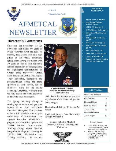
Page 3<strong>AFMETCAL</strong> NEWSLETTERApril 2011Volume 31, Issue No. 3Chief’s CornerFellow maintainers,On 18 February, we held aretirement ceremony for CMSgtMatt Brown to honor his 30 yearsof dedicated service. Although heis now retired, his impact on the<strong>Air</strong> <strong>Force</strong>, and the <strong>Air</strong> <strong>Force</strong>Metrology Program specifically,will not be forgotten.CMSgt Brown began his <strong>Air</strong><strong>Force</strong> career in October 1978.After Basic Military Training, hecompleted PMEL technicaltraining at Lowry AFB, Colorado.In October 1979, he was assignedto Kadena AB, Okinawa as anapprentice in the F-15 Type IVPMEL. CMSgt Brown leftKadena AB in April 1981 and wasreassigned to 443d <strong>Air</strong>craftMaintenance Squadron, AltusAFB, Oklahoma. He waspromoted to the rank of SSgt inApril 1982 and performed dutiesas a Laboratory Supervisor.However, Chief Brown elected toseparate from the <strong>Air</strong> <strong>Force</strong> inOctober 1982.He spent nearly 3 years in thecivilian workforce as a contractorin Saudi Arabia and a civil servantin Duluth Minnesota. ChiefBrown returned to active duty inMay 1985 and spent four years asa recruiter in Willmar, Minnesota.From there, he came back into thePMEL career field and assumedduties as a Type IIB PMELSection Supervisor and QualityProgram Manager for the 28thField Maintenance Squadron atEllsworth AFB, South Dakota. InMarch 1991, he was promoted toTSgt and was reassigned to the20th Component Repair Squadronat RAF Upper Heyford, UnitedKingdom.During his tour at RAF UpperHeyford, Chief Brown had twounique opportunities. In additionto shutting down the PMELbecause of base closure, he wasalso challenged with attempting totrain a rebellious SrA Niemann.After his tour in the UnitedKingdom, Chief Brown wasassigned to the 56th ComponentRepair Squadron, Luke AFB, AZas a Type IIB PMEL SectionSupervisor and Quality ProgramManager. CMSgt Brown waspromoted MSgt in February 1996and received orders back toOkinawa in August 1996, wherehe served as the F-15 Type IVPMEL Chief and TMDE FlightSuperintendent.He left Okinawa in August 2000and reported to McGuire AFB,New Jersey, where he waspromoted to SMSgt. CMSgtBrown spent nearly 5 years atMcGuire as the TMDE FlightChief. In July 2005 he reported toChief Master SergeantCraig “Woody” NiemannChief, Laboratory CertificationBranchOsan AB, Republic of Korea,where he was promoted to ChiefMaster Sergeant. And, in August2006, he assumed duties as theChief of the Laboratory CertificationBranch, where he was onceagain cursed with trying to keep aSMSgt Niemann in line.During his time at <strong>AFMETCAL</strong>,CMSgt Brown deployed for over450 days to 51 different locations.In addition to completing almost320 over-the shoulder evaluations,he also spearheaded the re-write ofthe input wiring directives,(Continued on page 4)
Page 4<strong>AFMETCAL</strong> NEWSLETTERApril 2011Volume 31, Issue No. 3Chief’s Corner (continued)(Continued from page 3)TO 33-1-32. CMSgt Brown also served as a key member of the improvement effort to revise the PMELQuality Program and shift the focus to a process-based, improvement effort.As CMSgt Brown and his wife Barb transition into civilian life back at Rapid City, South Dakota, the entireassessment team wishes him all the best. His outstanding dedication and leadership will be sorely missed.C. “Woody”. Niemann, CMSgt, USAFChief, Laboratory Certification BranchNews and NotesNew PMEL Training Manager at KeeslerPlease join me in welcoming Mr. Joseph Persons as our new PMELTraining Manager at Keesler AFB. Mr. Persons replaces Mr. BobMartin who served us well, but has decided to move on to otheradventures. Mr. Persons assumes his new role with a wealth of Metrologyexpertise. He attended the Basic Metrology course (Army side) atLowry AFB, CO, and graduated in December 1980. He then went on towork in calibration laboratories at various locations throughout theUnited States and Europe, to include a deployment during OperationDesert Storm. In 1994 he was directly involved in relocating the ArmyPMEL schoolhouse and Army Detachment from Lowry to Keesler.Once at Keesler, he served as the Army 1 st Sgt and retired from activeduty in April 1996. In October 1996, he obtained a civil service positionas an instructor in the <strong>Air</strong> <strong>Force</strong> PMEL Basic Apprentice Course. Hetaught various blocks throughout the Basic Course until he waspromoted to a Training Specialist position in June 2005. In this capacityhe managed the Phys/D Course, then the TACAN Course, and mostrecently the PMEL Basic Apprentice Course.We are pleased to have a Training Manager with solid PMEL and instructor backgrounds. Mr. Persons’primary goal is to continue to improve the quality of training at Keesler. He is committed to producing bothoutstanding PMEL apprentices and providing critical Advance Measurement Courses that meet our field’sneeds. One of Joe’s first challenges will be to help shape our career field by hosting our Utilization &Training Workshop in April 2011. Good luck Joe, we look forward to working with you as our new TrainingManager!CMSgt Donald R. ErdenMAJCOM PMEL Functional ManagerHQ AETC/A4MSAPictured above:Mr. Joseph H. Persons Jr.332 TRS PMEL Training Manager
Page 5<strong>AFMETCAL</strong> NEWSLETTERApril 2011Volume 31, Issue No. 3News and Notes (continued)<strong>Air</strong> <strong>Force</strong> Primary Standards Laboratory (AFPSL)Technical Order (TO) DepartmentThis article has been written to provide the field a better understanding with regard to function andrequirements of the <strong>Air</strong> <strong>Force</strong> Primary Standards Laboratory (AFPSL) TO Department in Heath, Ohio.The department consists of a manager, administrative assistant, draftsman, technical librarians, editors, teamleads and technical writers. All the men and women in the department have many years of experience with theMetrology Program and technical writing. The <strong>Air</strong> <strong>Force</strong>, Navy, and Army are well represented and ourcalibration backgrounds are pretty extensive and quite varied. We have a number of retired military servicepersonnel, a few who were on the <strong>Air</strong> <strong>Force</strong> Evaluation Team, and former government Technical ContentManagers (TCMs). Using the previous five complete years of historical data, we process an average of 1,180TOs in a year.The TO Department Requirements and References include the following documents:MIL-STD-38784MIL-PRF-38793<strong>AFMETCAL</strong> TO GuideTO 00-20-14 AF Metrology, Calibration ProgramTO 00-5-3 AF TO Life Cycle ManagementTO 00-5-1-WA-1 <strong>Air</strong> <strong>Force</strong> Technical GuideCalibration Requirements Documents (CRDs)Bionetics TO Work Instructions (5 Active)Bionetics is responsible for developing, publishing, and distributing all <strong>Air</strong> <strong>Force</strong> calibration technical orders.The <strong>Air</strong> <strong>Force</strong> Metrology and Calibration (<strong>AFMETCAL</strong>) Program provides oversight, inspection, anddirection to ensure requirements of the contract are met. There are several categories of TO development,depending on the circumstances. A New calibration technical order is developed for new equipment acquiredby the <strong>Air</strong> <strong>Force</strong>. A Revision or Change is usually the result of inputs from an <strong>Air</strong> <strong>Force</strong> PrecisionMeasurement Equipment Laboratory (PMEL) or other customers. This type of TO development work usuallydoes not require an extensive update. A Rewrite is an extensive update of an existing technical order due tochanges in calibration standards or techniques used to support the end item. The graphic on the next pagedepicts the process and flow for the development and maintenance of USAF calibration procedure technicalorders.(continued on page 6)
Page 6<strong>AFMETCAL</strong> NEWSLETTERApril 2011Volume 31, Issue No. 3News and Notes (continued)(continued from page 5)AFPSL TO Department (continued)As the graphic depicts, there are many steps in processing a TO. Each step adds time to the overall processbefore a TO can be fielded.The following is an Allotted Process Time (step 3 in the graphic above) for each type of TO:New: 90 calendar days from receiptRevision: 60 calendar days from receiptRewrite: 60 calendar days from receipt(Continued on page 7)
Page 7<strong>AFMETCAL</strong> NEWSLETTERApril 2011Volume 31, Issue No. 3News and Notes (continued)(Continued from page 6)The following information was compiled as of February 24, 2011 to give an idea of the workload in thedepartment as this article is being researched:K Area TeamsAFPSL TO Department (continued)TOs in WorkK1, K2, K8 & K9 New, 7Rewrite, 1Revision, 32K3 & K4 New, 20Rewrite, 4Revision, 74K5, K6, & K7 New, 5Rewrite, 2Revision, 23This equates to 166 individual TO work packages at some stage of development in the process. All work ineach section is verified by a Team Leader for the section. All work for the department is verified by atechnical editor and by a format editor. This workload does not include the additional AFTO Forms 252 thatare added after work has been started or the additional AFTO Forms 252 initiated to add multiple P/Ns to ageneral procedure.Our workload varies according to the amount of AFTO Forms 22 generated by field technicians and approvedby <strong>AFMETCAL</strong> and the result of <strong>AFMETCAL</strong> calibration determinations for new equipment entering the AFinventory. <strong>AFMETCAL</strong> must complete review of AFTO Forms 22 and calibration determination processingbefore work is tasked to the TO department. Thus, when an approved AFTO Form 22 or a calibration determinationdrives the need for either a TO update or a new TO, over 2 months may lapse before the tasking arrivesat the TO department.Once the job is tasked to the TO Department, the technical information has to be extensively researched foreach newly added test instrument (TI) or with any changes being made for an existing TI. Internallydeveloped spreadsheets are completed to prove every limit for each test point in the procedure and to verifyany
Page 8<strong>AFMETCAL</strong> NEWSLETTERApril 2011Volume 31, Issue No. 3News and Notes (continued)(Continued from page 7)AFPSL TO Department (continued)while automated calibrations are being performed, etc.; but as a general rule, the test equipment calibration iscompleted before moving to the next type or piece. To illustrate the point, as a K1, K2, K8, and K9 writer, Icurrently have 3 of the 7 New TOs, the 1 Rewrite TO, and 12 of the 32 Revision TOs in work at the time ofthis writing. The dates due to <strong>AFMETCAL</strong> for these TOs range from March 4, 2011 to May 9, 2011. Myprimary focus is directed towards the Revision TO due first, but I also have to be aware of the TOs that follow.I must determine how much time is required to process all other TOs in a timely manner to allow the team leadand editors the time they require to perform their functions. The TO process clock never stops. Holidays,vacations, fire drills, etc., all take time away from the development process. With all of these TOs scheduledand in process, no matter how great our focus is on a TO, we can get a Rapid Action Change on a different TOfor which we have to stop and re-direct our attention and efforts to perform the change in the requiredmaximum of 10 calendar days. All writers consistently have significant workloads and the constant effort toensure all documents are being processed towards their completion requires a real balancing act. The constantinterruptions; phone calls, questions, E-mails, meetings, etc.; all break concentration, and we change our focusor have to recall exactly where we were in the process. (At my age, the recall thing is the greatest challenge.)To give you an idea of the scrutiny each TO undergoes, another area I would like to address is the inspectionprocess. Again, since I am writing this article, I will use myself as an example. I recently wrote a new TO fora Handheld Digital Multimeter Series, and it went through many changes in the process. Every word writtenwas inspected and evaluated by the team lead, technical editor, and format editor a number of times during thedevelopment process. It was turned in to <strong>AFMETCAL</strong> and evaluated by the TCM and the Technical OrdersQuality Assurance Personnel (TOQAPs). The TOQAPs also performed the grading of the procedure. After allthe inspections, it was determined that I had entered an incorrect specification range adder on theThermocouple Measurement section of the spreadsheet for one of the TIs. This caused two incorrect values inthe TO in the limits being tested. The TO was returned for correction. I use this point to illustrate theinspection process which continues even after we complete our own comprehensive internal reviews. FromJanuary 2009 through August 2010, the department completed over 1,500 TO packages, resulting in anastounding 98 percent pass rate for the time period. So to sum up the inspection process, all of the writers'work is inspected and evaluated by at least 5 people, they are graded on 100 percent of their workload and(Continued on page 9)Pictured at left (L to R):Robert Deaver, TO Department QA;Chris Jewell, Scott Hummel, AFPSL techniciansperforming a validation on a TO.
Page 11<strong>AFMETCAL</strong> NEWSLETTERApril 2011Volume 31, Issue No. 3News and Notes (continued)Self-Sufficiency CodesAnnually, <strong>AFMETCAL</strong> publishes a Logistics Analysis Report. The report is prepared and provided to<strong>AFMETCAL</strong> program personnel with performance data for use in determining equipment acquisitionrequirements.One part of the Logistics Analysis Report is Self-Sufficiency. The data is retrieved from the PrecisionMeasurement Equipment Laboratory (PMEL) Automated Management System (PAMS) 7808 Report (AFTOForm 80 for non-PAMS users).During the Self-Sufficiency analysis, we have seen some disparity in the reporting of PMEL Self-Sufficiency.The default selection in PAMS is K100 Directed and it seems a majority of inputs use the default selection.For example, we noticed a base that was part of the TO 33K-1-100-2 Note (i.e. N29) sent items for lateralsupport and put the reason code as KOD (K100 Directed). If the base is part of the Note, then it is not K100directed. In this case, the reason for lateral support should have been SIO (Standards Inoperative).Below is some information to assist in selecting the correct Self-Sufficiency Code in PAMS. This willhopefully help in standardizing PAMS inputs so the Self-Sufficiency data can be better analyzed and betterservice provided to the field.Also, a decision tree/flow chart has been placed on the AF Portal, Metrology & Calibration, Products andServices, Customer Support.Self-Sufficiency:CODECONKODKPDLOELOFLOKLOPLOQLOSSIOMFRWAROTHDESCRIPTIONContract RepairK100 DirectedK Procedure DirectedLack of EnvironmentLack of FacilityLack of SkillsLack of PersonnelLack of EquipmentLack of Standards (Type IIA)Standards InoperativeManufacturer RepairWarrantyOther(Continued on page 12)
Page 12<strong>AFMETCAL</strong> NEWSLETTERApril 2011Volume 31, Issue No. 3News and Notes (continued)(Continued from page 11)Self-Sufficiency Codes (continued)KOD (CMS, K100 Directed) - Use when the published TO 33K-1-100-2 or CMS Cal Responsibility directs asource of support (i.e. Note Codes (N9, N10, N59A, N64, etc.), AFPSL, PMEL 2A (TYPE IIA), PMEL 68(DEG), and CONTRACT.KPD (K Procedure Directed) - Use when the published TO 33K-1-100-2 or CMS Cal Responsibility is PMELand the 33K Series Calibration procedure requires a source of support such as PMEL 68º room.LOS (Lack of Standards) - Use when the published TO 33K-1-100-2 or CMS Cal Responsibility is PMEL andyour PMEL is not authorized the equipment to support this requirement. DO NOT use this code if the CalResponsibility has a Note code (N9, N10, N59A, N64, etc.) or AFPSL, PMEL 2A (TYPE IIA), PMEL 68(DEG), and CONTRACT.LOQ (Lack of Equipment) - Use when the published TO 33K-1-100-2 or CMS Cal Responsibility is PMELand your PMEL is authorized the equipment to support this requirement, but do not have equipment on hand.CON (Contract Repair) - Use when the published TO 33K-1-100-2 or CMS Cal Responsibility is PMEL/CONTRACT where the PMEL is responsible for calibration. Maintenance support will be obtained from acommercial source. DO NOT use if the Cal Responsibility is CONTRACT.MFR (Manufacturer Repair) - Use when the published TO 33K-1-100-2 or CMS Cal Responsibility is PMELand the item have to be sent to a commercial repair facility. DO NOT use this code if item is still under Warranty.SIO (Standard Inoperative) - Use when the published TO 33K-1-100-2 or CMS Cal Responsibility is PMELand your PMEL is authorized the equipment to support this requirement but your standard on hand is inoperable.WAR (Warranty Repair) - Use when the published TO 33K-1-100-2 or CMS Cal Responsibility is PMEL andthe item has to be sent to a commercial repair facility for repair under warranty conditions.LOE (Lack of Environment) - Use when the published TO 33K-1-100-2 or CMS Cal Responsibility is PMELand your laboratory environment is inoperable/out of tolerance to the point lateral support is required. DONOT use this code if the Cal Responsibility is PMEL 68 (DEG) unless your laboratory has 68º room and theenvironment is inoperable/out of tolerance to the point lateral support is required.LOF (Lack of Facility) - Use when the published TO 33K-1-100-2 or CMS Cal Responsibility is PMEL andyour laboratory does not meet requirements for the calibration of that item. DO NOT use this code if the CalResponsibility is PMEL 68 (DEG).LOK (Lack of Skills) - Use when the published TO 33K-1-100-2 or CMS Cal Responsibility is PMEL andyour laboratory does not have a qualified technician to support the requirement.(Continued on page 13)
Page 15<strong>AFMETCAL</strong> NEWSLETTERApril 2011Volume 31, Issue No. 3News and Notes (continued)The Chronicles of the <strong>AFMETCAL</strong> Buy Program-Good Things Cometo Those Who Wait (continued)(Continued from page 14)Using actual data from <strong>AFMETCAL</strong> 2011 acquisitions (averages of timelines identified during acquisitionplanning of what is anticipated to be required to satisfy contract requirements), there are several key milestonesthat occur after a contract is awarded:• Delivery of a Engineering (draft) copy of the equipment manual (operation, maintenance, calibration,etc) for evaluation (typically 30-90 days after contract award, planned average 60 days)• Completion of <strong>AFMETCAL</strong> Engineering TCM review of equipment manual (average 30 days)• Delivery of Corrected Final Engineering copy equipment manual for approval (average 30 days)• Delivery of the first (article/production) equipment item to the AFPSL for acceptance testing (typically90-180 days after contract award, planned average 139 days)• Completion of first (article/production) equipment item acceptance testing at the AFPSL (typically 30-90 days after delivery of the item, planned average 57 days)• Delivery of final Logistics copy of the manual (typically 30 days after completion of first article testing)• Cataloging action submitted to WR-ALC for request for National Stock Number (NSN) (completedsimultaneously with the above)• Delivery of NSN (typically takes a minimum of 45 days)• Equipment Support Plan completed and posted/Submittal of PMEL requisitions (completed simultaneouslywith the above)• Delivery of production units to the AFPSL for acceptance testing (typically 90-120 days after first article/productionacceptance, average 98 days)• Completion of acceptance testing of production units (typically takes 30-60 days for AFPSL acceptance,average 39 days)The chart below shows an average of 333 days from contract award to the first shipment of production items.These numbers reflect an average of what is planned; it is not necessarily what actually happens. Some buystake longer, some less, some are expedited, some are delayed. But it is a good representation of what happensafter a contract is awarded.(Continued on page 16)
Page 18<strong>AFMETCAL</strong> NEWSLETTERApril 2011Volume 31, Issue No. 3From The Bench (continued)HP/Agilent 3458A CAL RAMRecently at Misawa, we experienced a hardware failureon one of our 3458A Multimeters. As we powered theunit on, we would receive error messages 101 –“CALIBRATION ERROR”; 109 – “OUT OFCALIBRATION”; or 110 – “CALIBRATION RE-QUIRED”. The first sign of a problem was the internaltemperature, which was completely erratic; measuringPictured above:HP 3458A Digital Multimeter(OEM Photo)from -245 deg C to 150 deg C internally; and completely random. We tried recycling to the power whichcaused the multimeter to display the error messages above. We then tried running the autocal and artifact calbut, both rendered error messages 205 – “Cal value” and 210 – “Cal Require”. <strong>Base</strong>d on the error codes in theservice manual, we were able to narrow the fault down to circuit card assemblies A1, A2 and A5.While investigating this issue we found out that the manufacturer of the 3458A, Agilent Technologies, publisheda Service Notice dated 3 DEC 2010. This notice addressed and issue with the CAL RAM that wouldcause the following error messages.1. Error 101, “CALIBRATION ERROR”2. Error 109, “OUT OF CALIBRATION”3. Error 110, “CALIBRATION REQUIRED”4. “RAM TEST -----------------“The CAL RAM consists of three integrated circuits on the A5 assembly (U121, U122 and U132) that containcal data stored in the memory. Each circuit has a long life battery which allows each CAL RAM to retain datain memory even when the 3458A is off. The life expectancy of these batteries was 10 years from manufacture.These batteries will eventually discharge and cause loss of data within the CAL RAM but, there’s no guaranteethat the failure will occur during the life of your equipment.Download the 3458A-15D Service Notice here:http://cp.literature.agilent.com/litweb/pdf/3458A-15D.pdfIn order to correct this problem, replacement of the CAL RAM integrated circuits is required. In addition, acomplete adjustment and calibration should be accomplished, to include SCAL.”TSgt Antonio WashingtonMisawa PMEL35 MXS/MXMD
Page 19<strong>AFMETCAL</strong> NEWSLETTERApril 2011Volume 31, Issue No. 3From The Bench (continued)TEGAM 1830A Power Meter: Loading Calibration Factorsfor Multiple SensorsPictured above:TEGAM 1830A Power Meter(OEM Photo)The TEGAM manual, 1830A-901-01 dated June 4 th , 2010provides good instructions on how to connect your 1830A viaLXI webpage and how to upload calibration factors into the1830A. These instructions can be found on pages 4-17 and4-29, respectively. Page 4-29 states that multiple sensors canbe uploaded, but it doesn’t state how to do this. Problem is onlyone file can be uploaded into the 1830A at a time, so all thesensors have to be created on one file. The following areinstructions on how to accomplish this:After connecting your 1830A to your computer, follow theTEGAM manual, page 4-17, heading “LXI Webpage” heading to gain access to the 1830A full menu.Page 4-29, Sensor Calibration File Upload, explains how to create a .csv file and upload it into the 1830Athrough the LXI Webpage. Figure 4.13 shows what the .csv file should look like, but only shows one sensor.To load multiple sensors into the 1830A, the .csv file needs to contain the information for all sensors you wantto load. To do this, insert a blank row between each sensor’s data. See the example below:# 1830A SensorConfiguration Data# Serial Number Frequency Units K Factor70064 10 MHz 0.998170064 30 MHz 0.997870064 50 MHz 0.9977# Serial Number Frequency Units K Factor111 10 MHz 0.9982111 30 MHz 0.9978111 50 MHz 0.9977# Serial Number Frequency Units K Factor5395 18 GHz 1.19115395 19 GHz 0.9944To add a sensor or change a sensor cal chart, just make the change to the stored .csv and upload the new file tothe 1830A through the LXI interface. This will overwrite the existing file. As always, verify the cal factors inthe 1830A are correct after uploading.Mickie Green & John OlsonOffutt PMEL
Page 20<strong>AFMETCAL</strong> NEWSLETTERApril 2011Volume 31, Issue No. 3From The Bench (continued)Bore Gage CalibrationFor several years now the calibration procedure for bore gages hasincluded the standard measuring machine/supermicrometer as thepreferred method. Recently, two PMELs called me and said they couldnot achieve repeatability using this method. So, I did some research andfound that this process has been in the TO since inception in 1970. Ispoke with some manufacturers along with some PMEL techniciansabout this calibration process. There are three types of bore gages:micrometer type, dial or digital spring type with two opposing anvils, anddial or digital spring type with three measuring anvils. The first twotypes can be measured on the standard measuring machine/supermicrometer. The type with three measuring anvils has to strictly bemeasured using ring gages. The problem is the alignment of the TI to thestandard measuring machine/supermicrometer measuring anvils. Alongwith the alignment, the Calibration TO specifies a measuring force of 16oz, which seems to be low in some cases. The calibration TO will bechanged to allow the technician to select a measuring force. Manytechnicians have procured or developed fixturing to ensure proper alignment of the TI to the measuring anvils.This would be dependent on the accuracy of the TI. The micrometer type TI would be easier to measure usingthis method than the spring type because the tailstock is also spring loaded. The thought process is that thetailstock pressure be at least twice the TI spring force to reduce influence on the TI measurement. The springis mostly reduced from the process when the tailstock force is moved to the maximum force on thesupermicrometer and Mahr 828.If you have any questions please feel free to contact your country manager.Pictured above:Agilent 33220A Function/Arbitrary Waveform Generator(OEM Photo)Doing Phase With The 33220AGenerating phase offsets has been the province of thevenerably old 3325A, but the 3325As will not lastforever. Our lab had gotten one of the new 33220AFunction/Arbitrary Waveform Generators, with theTime <strong>Base</strong> Option, so that it can be phase-locked toother generators, and I wondered to myself whether itcould be set up to do phase offsets, just in case weever lost our 3325A.Well, yes, it can. For Sine, Square and TriangleWaves one can do phase offsets with the 33220Asimply by operating the Generator in Burst FunctionGated Mode. You do not need to use a gating signal(Continued on page 21)
Page 21<strong>AFMETCAL</strong> NEWSLETTERApril 2011Volume 31, Issue No. 3From The Bench (continued)(Continued from page 20)Doing Phase With The 33220A (continued)if you select NEG Gate, because with no input on the Gate Input BNC the Generator will ‘think’ it is getting anegative gate signal -- using Neg Gate is therefore like turning on an output enable switch. In the Burst Menu,after you select Gated Mode, the phase control section of the menu pops right up.What about pulses?, you may ask. Doing phase offset pulses is a bit trickier, as the pulse function does notallow for the same gated phase control as do the Sine, Square and Triangle Functions. But one can simply usethe ARB Function to create a pulse, and from the ARB function you can do both gated and triggered phase offsets.When setting up an Arbitrary Waveform, remember on the first ARB Menu to turn INTERP to OFF, soyou will get vertical edges on your pulses. To create a single pulse requires only 2 ARB Points – in the firstpoint set your pulse positive voltage, and in the second point set your negative pulse voltage or baseline alongwith your pulse width time, see below:Point 1: Voltage 5VPoint 2: Time 6uSVoltage 0VThis gives you a single 6uS pulse.From there you can go to Burst and either Trigger your arbitrary waveform or turn it on with Neg Gate as withthe Sine, Square and Triangular Waveforms. Remember, to be phase locked with another generator, you musttie the time-bases together, and use the same frequency or a multiple of the same frequency or period with bothgenerators, unless you select Burst Trigger Mode and then you can use the second generator’s SYNC Out totrigger your ARB waveform, and then it will be phase locked to the second generator’s Trigger Signal. Insome Avionics and TACAN applications you might need to vary the position of a pulse after a TI triggerpulse, and this is where the 33220A can be very useful, creating the desired pulse or pulses with the ARBFunction and sliding them into position using Burst Phase.Since some Avionics applications require a double pulse, we should take a moment to discuss Double Pulses.With the 33220A ARB Function, INTERP OFF, a double pulse takes only 4 points – 1 st point defines yourhigh amplitude, 2 nd point defines your pulse width and baseline amplitude, 3 rd point defines your pulse spacing– the time distance between your two pulses, and the 4 th point, well, just add your desired pulse width to thepulse spacing time of the 3 rd point, see as follows:Point 1: Voltage 5VPoint 2: Time 6uSVoltage 0VPoint 3: Time 24uS Voltage 5VPoint 4: Time 30uS Voltage 0VThis gives you two pulses, 6uS wide and spaced at 24uS.(Continued on page 22)
Page 22<strong>AFMETCAL</strong> NEWSLETTERApril 2011Volume 31, Issue No. 3From The Bench (continued)(Continued from page 21)Doing Phase With The 33220A (continued)The old 3325A had a Phase Zero function, allowingany phase position to become the new zero degreereference point. The 33220A doesn’t have that.But the easy way to verify the 33220As phase accuracybefore you use it for any traceable phase offset,since I do not believe it is a calibrated function,would be to use a 53131A or 53132A Counter inPhase mode, set the 33220A to zero degrees and runit to Counter CHA , and your second generator withlocked time-base, run it to Counter CHB, and thenwhatever your 53131A counter reads, enter the samenumber into its OFFSET Function, but with the oppositepolarity. Phase measurements come out almostentirely nominal, that is, when measuringphase between two square-waves. Using squarewaves minimizes the trigger slew error characteristicof measuring phase between sine or triangle waves(slew error being the slight differences in time whenPictured above:Mr. Scott WeissAndersen PMELtriggering along a slant or a slope if the vertical amplitude of the trigger should vary even by slight amounts,but if the waveform has a perfectly vertical edge, such as with a square wave, then no slew error can theoreticallyexist as differences in the vertical trigger result in no horizontal time displacement).You can also verify phase accuracy using one of those new generation high accuracy digital oscilloscopes,such as the LeCroy LC584 or the Tektronix TDS5054. You might be able to do the job with cursors andzoom functions, but it’s probably easier to just use DELAY – set your zero degree reference, where your twogenerators coincide, using 0.0 delay and then check your cardinal phase points by loading in target DELAYs,and then adding or subtracting 90, 180 and 270 degrees to your 33220A degree setting. For instance, if youare using a phase signal of 100KHz, well, that is a period of 10uS. So your 90, 180, and 270 degree delay targetswould be 2.5, 5.0 and 7.5uS’s respectively. If you take your Period of 10uS and divide it by 360, thisgives you your time per degree, which in this case is 27.7777nS per degree. Again, my 33220A was hittingthe delay targets right on the line, and what jitter I was getting was probably from the 3325A which I was usingas the second reference generator (the jitter we see on delayed signals is classic Phase Noise, and if youcan actually watch it squirm back and forth, then it is probably phase noise in the 1Hz to 100Hz offset rangewhere phase noise tends to be highest).If you are unsure how to calculate tolerances of your digitizing scope or are unsure of its accuracy, simplytransfer the accuracy of a known accuracy waveform, such as measuring the period of your 100KHz signal -whether you use cursors or set in a delay of 10 uS, you will find that these scopes return readings that are virtuallynominal.(Continued on page 23)
Page 23<strong>AFMETCAL</strong> NEWSLETTERApril 2011Volume 31, Issue No. 3From The Bench (continued)(Continued from page 22)Doing Phase With The 33220A (continued)So if your lab owns 33220As then you shouldn’t have to worry too much about nursing along your 3325As.But if buying a new 33220A, remember to ask for the Time <strong>Base</strong> Option, as the standard model without a time-base Input/Output is virtually useless. So many checks nowadays requires that all the instruments be timebase phase locked together…so whatever the extra cost of the Time <strong>Base</strong> Option, it is well worth it.Scott WeissPMEL Technician, Andersen AFBEditor’s Note: Chief Niemann would like to remindall technicians that the contents of this article (orany newsletter article) do not replace the requirementto use valid technical data prior to attemptingrepair or calibration of any item of TMDE.You have a Starrett 120A caliper in for calibration.The crystal is yellow, the depth rod must be re-zeroedfor depth measurements, the pointer is at the 3o’clock position, and it is dirty. You clean it up aStarrett 120 Caliper RepairPicture above:Starrett 120A Caliperlittle and start the calibration. You find one or two outside measurements do not meet specifications. Youhave several options, the customer takes a limitation, you NRTS it, or you can repair it.A 6 inch Starrett 120 caliper can cost from $162 to $251. One with long jaws is $372. The 9 and 12 inchcalipers can run from $253 to $331. You can repair these calipers with less than $20 in parts and some time.With today’s budget cuts it does not make sense to NRTS a caliper that can easily be repaired.I have been repairing dial calipers and indicators for over 10 years. Caliper repair is straightforward and theStarrett 120 series is the easiest. The Brown and Sharpe and Mitutoyo calipers can be repaired without muchdifficulty; you just need to understand how they work.You will need a couple of needle pullers, a crystal press, and a few parts. I will list part numbers at the end ofthese instructions.Most of the Starrett needles are pressed on the pinion very tight and the first time you remove the needle youwill need a Mitutoyo hand/needle remover. If a needle is not pressed on too tight Bergeon makes several pullersthat work well. The Presto 7 has four pin diameters that will work for small needles through the Starrettneedles. The only issue is the smallest pin will break leaving a short stub. However, after it breaks it will stillwork for smaller needles.(Continued on page 24)
Page 24<strong>AFMETCAL</strong> NEWSLETTERApril 2011Volume 31, Issue No. 3From The Bench (continued)(Continued from page 23)Starrett 120 Caliper Repair (continued)You can buy a case closer from a jewelry tool supplier for around $35 and make some modifications or youcan buy a crystal press from Mitutoyo or Long Island Indicator for around $215. The lower dies on the casecloser are flat and on the crystal press they are convex. You can use a piece of CTK foam to resolve the issueor you can have it machined. There is a picture of a lower die with foam below; try to trim around the outsideon an angle.Pictured at left:Lower die with CTK foamIf you are going to be buying from a jewelry store supplier, get with your financial folks to get approval to useyour government credit card. The savings of $180 should be enough to get the approval.Part number/nomenclature references are page 1 of 14 of the 120 Dial Caliper parts break down.Problem: The slide stop (27) is missing.Solution: Replace the slide stop.Issues: There are three styles of depth rods and two styles of slide stops. If the depth rod covers the gear rack(9) use part number PT27366 (27). With the other two, there is a gap between the gear rack and depth rod.Originally, there was a spring “L” inserted into a slot located under the slide stop. See Picture. It is no longeravailable and was replaced by part number PT19045. This slide stop has a web sticking down that goes betweenthe depth rod and rack. Unfortunately, one of the depth rods is wider than the other and it may notwork. You can try to shave the finger down to thin it but that does not work well. One option is to look at thecalipers when they come in for calibration. If they have the spring, “L” and the PT19045 stop will work installthe new slide stop and retain the spring “L” for those calipers where the PT19045 stop will not work.Problem: Caliper requires re-zero for the depth measurement or the depth rod is loose.Solution: Close the jaws and lock the sliding jaw using lock screw (7). Loosen the four screws (12) on thedial plate (1). Put the end of the caliper against a parallel and push on the dial plate until the depth rod seatsagainst the parallel. Watch the needle and tighten the dial plate screws. If the needle moves when you tightenthe first screw loosen it and start a different screw. Once the dial plate is secure check the depth rod per thecalibration procedure.If you cannot resolve the problem by loosening the dial plate or the depth rod is loose you will need to dissemblethe caliper.(Continued on page 25)
Page 25<strong>AFMETCAL</strong> NEWSLETTERApril 2011Volume 31, Issue No. 3From The Bench (continued)(Continued from page 24)Starrett 120 Caliper Repair (continued)Loosen the bezel lock screw (29). Remove the bezel and crystal assembly (31) by prying under the bezel witha small screwdriver. Remove the needle (24) using the Mitutoyo hand remover. Remove the dial face (23)and dial friction spring (22). Remove the two small screws (19 & 20) holding the bridge (18). Remove thehand pinion (17). Remove the two screws (9) holding the detent spring (15) and remove the backlash gearassembly (16). The backlash assembly consists of a lower gear that engages the rack, a spring, and an uppergear. Together the upper and lower gears engage the hand pinion (17). The backlash spring fits between thetop and bottom gears. Each gear has a hole in it and the ends of the spring are bent to go in the holes. Thebacklash spring is not listed in the parts illustration; however, the part number is PT19038. Under the backlashassembly there will be one or two screws (14) that secure the depth rod. You may get some movement to getthe depth rod flush with the end of the caliper. You can try pulling the depth rod towards the end of the caliperwhile tightening the screws (14). Before you put everything back together, you will need to do some cleaning.Lift the bar out of the sliding Jaw. Remove the metal gib slide spring (2) and plastic gib slide (3). Clean therack (8) and the inside of the bar and sliding jaw. Make sure the rack is against the top of the bar and thescrews (9) are tight.ReassemblyThe steel gib slide spring (2) and plastic gib slide (3) have a small hole near one end and are located usingscrew (4). Screw (4) has a tip that fits in the holes to lock the two pieces in place. Once the caliper is assembled,screw (4) and screw (5) are used to adjust the gib slide.Locate the gib slide metal spring and gib plastic slide in the top of the sliding jaw. Make sure the holes fit onthe tip of screw (4). Very carefully slip the bar into place in the sliding jaw. Place the slide cover plate (1) ontop of the assembly and install screws (12). Snug but do not tighten the screws. Carefully lower the detentspring (15) and the lower backlash gear (16) through the slide cover plate insuring the lower backlash gear isin the notch in the detent spring. Start screws (9) and while pushing the detent spring towards the rack (8)tighten screws (9). After you put the backlash spring, top backlash gear, and hand pinion move the slide backand forth and listen to the gear assembly. If it is rough or noisy, loosen the two screws holding the detentspring. While pushing the detent spring toward the rack gear tighten the screws. Move the slide back andcheck the gears.Place the backlash spring PT19038 in the recess in the bottom backlash gear (16). Insure the end of the springis in the hole in the gear. Very carefully place the upper backlash gear on top with the hole lined up with theend of the spring. The upper backlash gear is flush on the bottom with a raised area on the top. When properlyassembled the upper gear will sit right on top of the lower gear. To verify the ends of the spring are properlyengaged in the upper and lower gears you can carefully rotate the top gear and when you let go it shouldspring back.Install the hand pinion (17) with the long end up. Install the bridge with the opening over the two screws (9)that hold the detent spring (15). Use care when tightening screws (19 & 20). If you did not get the fine adjust(Continued on page 26)
Page 26<strong>AFMETCAL</strong> NEWSLETTERApril 2011Volume 31, Issue No. 3From The Bench (continued)(Continued from page 25)Starrett 120 Caliper Repair (continued)stud/thumb screw (6) in place slide the jaw to the end of the bar until you can drop it in place. Install the slidestop.Close the caliper and lock the sliding jaw using screw (7). Place the end of the bar against a parallel and pushthe slide cover plate (1) until the depth rod is against the parallel. Carefully tighten screws (12).Install the dial friction spring (22), and the dial (23). Place the needle (24) on the hand pinion (17) pointing tothe 12 o’clock position. Use the flat side of a small screwdriver to push down to secure the needle on the handpinion.Install the bezel/crystal assembly (31). There are two types of bezel retainers. One is a wire spring (30) andthe other is a rubber o-ring (21). If you have the wire spring, you will need to push the spring under the bezeland work around the outside of the bezel until it pops in place. If you have the rubber o-ring, you can simplyrotate and push the bezel down until it pops in place. Install the bezel lock (28) and lock screw (29). Rotatethe bezel until the zero on the dial lines up with the needle and lock with screw (29).Assembly is complete and calibration can begin.Needle removers:http://www.bergeon.ch/images/news/news_1245309842.pdfNeedle removers are on pages 9 and 10. I have used the 30671-7 and the 2004 pullers. Both workwell. The 30671-7 is also referred to as a Presto 7.Pictured at left:Needle remover(OEM Photo)http://mitutoyo.com/TerminalMerchandisingGroup.aspx?group=1229This will take you to a repair kit that contains the needle remover and the crystal press.Crystal presses:http://www.esslinger.com/crystalpresscaseclosercombination.aspxPictured at left:Crystal Press/Case Closer Combination(OEM Photo)(Continued on page 27)
Page 27<strong>AFMETCAL</strong> NEWSLETTERApril 2011Volume 31, Issue No. 3From The Bench (continued)(Continued from page 26)Starrett 120 Caliper Repair (continued)Parts, hand removers, and the crystal press can be ordered from a number of sources. This is not an endorsementof Newark but I have ordered parts and tools from them and in many cases, they have assigned a Newarkpart number to the items. Parts can be ordered from most Mitutoyo and Starrett distributors.ToolsItem MFG/PN Newark PN CostNeedle remover Mitutoyo 901181 07P6205 135.00Needle remover Bergeron Presto 7 53.95Case closer Esslinger 59.01200 34.95Crystal press Mitutoyo 7000 213 (2008 price list)Starrett PartsItem Starrett PN Newark PN Cost Stock levelBacklash spring PT19038 14P5182 1.35 6Crystal PT19043 08P0835 1.40 10Stop Pad PT19045 12P9893 1.35 10Stop Pad PT27366 98M1599 1.50 10Bridge Screw PT05465 12P9897 1.35 4Bezel O-ring 23534-0 14P5168 1.35 6Bezel clamp PT19046 12P9908 1.35 4Hand/needle PT19035 12P9903 2.80 4Mr. Daniel Roach68 Degree Room TechnicianEglin PMEL
Page 28<strong>AFMETCAL</strong> NEWSLETTERApril 2011Volume 31, Issue No. 3From The Bench (continued)Software configurations per TO 33K6-4-889-1Double click the Optimar 100 icon. A popupmenu screen will appear with a CAUTIONWarning.Ensure that the Optimar 100’s spindle isunobstructed throughout its travel range. After clickingOK, the spindle will travel to the reference point.A) Creating a Test Piece test file or directory1 Select the Test Icon .Optimar 100 Analog Test Indicator4 The subfolders under the DMAFB PMEL folderwere created using the New function button. Thesesubfolders are grouped according to the “Type” of testpieces to be calibrated such as, “Comparators Analog”,“Dial Indicators Analog”, and “Test IndicatorsAnalog”.2 Select New from the Select Testpiece menuscreen to create a new test file gage name.The test piece file names are organized by “Accuracy”and “Range” to create a general list of test piece filescovering the various gage manufacturers under each“Type” of test indicators.Or, New group to create a directory file folder.3 In the following example, a sub directory folder"DMAFB PMEL" was created using the New groupmenu button under the Gage folder directory.Organizing the file structure using this method minimizesany redundancy in the test files created.5 After selecting New, the Testpiece Data- menuscreen will pop up. Select the desired type of test piece(Dial Test Indicator) from the Object drop downmenu, Standard specifications (ASME B89.1.10M-2001) and System of units measurement (inch or metric).Note: The standard specifications or calibration authorityis TO 33K6-4-889-1 and the specifications willbe configured in the Tolerance menu screen.(Continued on page 31)
Page 29<strong>AFMETCAL</strong> NEWSLETTERApril 2011Volume 31, Issue No. 3From The Bench (continued)(Continued from page 30)Optimar 100 Analog Test Indicator (continued)Automatic Measurement is used for digital gage orprobes. Leave this menu box uncheck.Stabilization Time is used if the gage is inert. Leavethis value to 0 ms (default).7 Tolerances tab, uncheck the Use tolerances of standardsmenu box. Enter the tolerance specificationsaccording to the current TO 33K6-4-889-1.After completion of configuring the Testpiece Data,click Further testpiece data... menu button.6 General tab, enter the “Indicator Range”,“Resolution and “Direction”. All other parametersnot mention are not applicable.Designation box 1 , enter the TO date and TO number. In theevent that the TO is updated, the TO date can easily beverified in the “Test Information Routine” menu screenupon execution of a test file.Direction, select “AB”, this is for clockwise andcounter clockwise direction.Indicator Range, enter the Dial Test Indicator’srange in the menu box.For example, a Dial Test Indicator (MarTest 801SM) has a range of +/- 0.004. From -0.004 inch to+0.004 inch equates to a total travel range of 0.008inch. In the Indicator range menu box, enter 0.008.Hint: After entering the Indicator range, click the “FromInch” menu box and the software will auto fill the “ToInch” menu box.Indicator Resolution, enter the test piece resolutionin either inch or micro inch. For example, enter0.0001 inch or 100 micro inches.Repeatability box 1 , can be left at the default. This is not anapplicable test function of TO 33K6-4-889-1.Hysteresis box 1 , enter the hysteresis in division(s) per TO33K6-4-889-1. Note: ASME B89.1.10M-2001 and TO33K6-4-889-1 differ in hysteresis specifications. Some testindicators follow manufacturer’s specifications and notASME specifications. Refer to AFCAV specifications.Accuracy box 1 , enter the accuracy in division(s) per TO33K6-4-889-1.Determine maximum deviation box 1, check this menu box.The maximum deviation will be the combined maximumdeviation recorded for the linearity and hysteresis data.If the Determine maximum deviation box is “unchecked”,the resulting data is the worst case point from only the Ingoingstroke on the indicator.(Continued on page 32)
Page 30<strong>AFMETCAL</strong> NEWSLETTERApril 2011Volume 31, Issue No. 3From The Bench (continued)(Continued from page 31 )Optimar 100 Analog Test Indicator (continued)Maximum Deviation looks at both In-going and Outgoingand reports the point furthest from zero. DeweyChristy (Mahr Federal)8 Testing Increment tab, check the “With EqualTesting Increment” radio button (default), set theIncrements per revolution menu box 1 to a value of 4(default) and the revolutions to a value of 1 (default).Hint: Since Test Indicators are normally one revolution,unless otherwise specified, selecting “Withequal testing increments” button will output fourequally test positions. Therefore, manual entry of thetest position is not required.9 Test tab, enter the over travel value in micro inchesin the Overtravel menu box. The over travel is the remainingtravel of the test indicator’s range.Positioning Path, this value can be set to any desiredvalue. When positioning the dial indicator’s needle tothe increment test point, the indicating needle must bemoved greater than the value set in the positioningpath.If not, an error popup menu will appear to warn youthat the positioning path is too short.Position Repeatability, this is not an applicable testper TO 33K6-4-889-1. The repeatability test is performedafter the linearity and hysteresis checks foreach measurement direction, Measurement A andMeasurement B.Hint: Upon completion of the hysteresis test, clickthe cancel button to bypass the Position Repeatabilitytest.If the Position Repeatability is set for a value of 1,the software will perform five (5) repeat test measurementsat 25% of the total span.At the default value of 3, the software will performfive (5) repeat test measurements for each test pointat 25%, 50% and 75% of the total span.Admissible change in direction, this can be left in thedefault value. The software will correct for the“Admissible change in direction” value if this value isoutside the software’s preprogrammed range.10 After entering the required test data, click OKtwice to exit the Further Testpiece Data- menuscreen.This will begin the calibration process.(Continued on page 33)
Page 31<strong>AFMETCAL</strong> NEWSLETTERApril 2011Volume 31, Issue No. 3From The Bench (continued)Optimar 100 Analog Test Indicator (continued)(Continued from page 32 )B) Selecting the Test Piece:1 Select Indicator Icon .2 Select the test piece from the lists and click OK.Click OK if the parameters are correct for the TI to becalibrated.4 The following menu screen below will appear. Preparethe Test Piece for calibration.3 The Testing Routine Information menu screenwill appear.Ensure that the test parameters are correct for theTest Instrument (TI) to be calibrated.The Tolerance date should match the current TechnicalOrder. If not, update the test piece test parameters.Refer to section A.7, Tolerances tab.5 If the distance from the anvil to the Test Indicator'scontact tip requires a large amount of travel distance tomake contact, there is a software function calledMeasuring Station that will move the anvil at a fasteror slower slew rate electronically.Click on the Extra menu button at the top, then selectand click Measuring Station from the drop downmenu. Click on either the up or down arrows to slewthe anvil close to the test piece’s contact tip.(Continued on page 34)
Page 32<strong>AFMETCAL</strong> NEWSLETTERApril 2011Volume 31, Issue No. 3From The Bench (continued)(Continued from page 33)Optimar 100 Analog Test Indicator (continued)The above pictures illustrates a properly mounted TestIndicator on the Optimar 100 using the appropriateadaptors, special anvil and attachments.Click OK to exit the Measuring Station menuscreen. Note: to avoid a popup error menu, approachthe test point starting from a clockwise direction(for cw dial indicators) and the dial indicator’sneedle must travel greater than the number of divisionset in the Positioning Path menu box. Refer tosection A.9, Test tab.5 CAUTION: When mountingthe Test Indicator, alwayshold the test piece when looseningthe clamping lever (17)for the setting position of thetest piece.Failure to hold the test piece will result in the testpiece colliding with the anvil causing damage toboth the Optimar 100 and the Test Piece.Mount the Test Indicator using the appropriate reducingsleeve, adaptors and/or attachments.Note: The Test Indicator’s stylus must be set to themeasuring surface per the manufacturer’s recommendangle. Failure to set the recommended stylus angle tothe measuring surface will result in cosine error.Adjust the clamping lever (17) to manually set theTest Indicator’s stylus as close as possible to the anvil,rough adjustment.7 Preloading of the Test Piece will be outlined in thefollowing steps listed below:a. Rotate the Test Instrument’sbezel and align the zero to theindicating needle.NOTE: The indicating needle isat the “mechanical restposition”.Refer to the picture at right.b. Next, rotate the Test Instrument’sbezel 180 degrees plusthe preloaded divisions perTO 33K6-4-889-1.Refer to the picture on the right.(Continued on page 35)
Page 33<strong>AFMETCAL</strong> NEWSLETTERApril 2011Volume 31, Issue No. 3From The Bench (continued)Optimar 100 Analog Test Indicator (continued)(Continued from page 34)c. Set the dial indicator's needle to zero by rotatingthe Optimar 100's rotary knob (15) in a clockwisedirection, fine adjustment. Refer to the picturesbelow.This will be the initial zero reference position forthe dial indicator and the Optimar’s anvil.6 On the Measure screen menu, click the right arrowmenu button to record the initial zero referencedata.The test measurement will bedivided in two sections.Measurement A checks the TestIndicator in one direction andMeasurement B in the oppositedirection.NOTE: The green arrow in the Measure menuscreen indicates whether you rotate the Optimar 100’srotary knob clockwise or counter clockwise.Up arrow for clockwise direction. Down arrowfor counter clockwise direction.The next increment test point will be displayed inthe Next testing position menu.needle in a counter clockwise direction and positionthe indicating needle a couple of divisions before thetest point.This test point will be the negative portion of the TestInstrument’s total range.Rotate the rotary knob (15) to place the indicating needleon the test point. Note the rotation by the positionof the green arrow in the Measure menu screen.Click the right arrow menu button to record thedata and position the anvil to the next test point for theremainder of the calibration.Refer to the Next testing position menu box locatedin the Measure in Direction A menu screen to view thenext test point.To repeat a test point, click the left arrowbutton.menu7 After completion of the linearity and hysteresisverification test, the user can omit the repeatability testsince this is not a calibration function per the TO33K6-4-889-1.Click Cancel to bypass the repeatability test and continueto Measurement B.8 Upon completion of the Measurement A, rotate theOptimar 100’s rotary dial in a counter clockwise directionto continue the calibration for Measurement B.After the right arrow menu button is clicked,the Optimar’s software will slew the Test Indicator'sContinue to rotate the rotary dial until the upper portionof the special anvil attachment makes contact withthe Test Instrument’s stylus.(Continued on page 36)
Page 34<strong>AFMETCAL</strong> NEWSLETTERApril 2011Volume 31, Issue No. 3From The Bench (continued)(Continued from page 35)Optimar 100 Analog Test Indicator (continued)Align the Test Instruments indicating needle on the zero test point, as displayed in the Next Testing Positionmenu box in the Measure in Direction B menu screen.Repeat steps 6 & 7 to complete the calibration of Measurement B.9 Verify that the TI meets the accuracy tolerance per the TO. This can be view in the upper right hand blockof the calibration menu screen.Use the vertical scroll bar to view Measurement A and Measurement B.This setup guide may differ depending on the Test Instrument used. The Test Instrument used for this setupguide is a Mahr Federal 801 SM.Mr. Girard IbanezDavis-Monthan PMEL355 CMS/MXMD
Page 35<strong>AFMETCAL</strong> NEWSLETTERApril 2011Volume 31, Issue No. 3From The Bench (continued)Software configurations per TO 33K6-4-889-1Double click the Optimar 100 icon. A popupmenu screen will appear with a CAUTION Warning.Ensure that the Optimar 100’s spindle is unobstructedthroughout its travel range. After clickingOK, the spindle will travel to the reference point.A) Creating a Test Piece test file or directory1 Select Indicator Icon .Optimar 100 Analog Dial Indicator2 Select New from the Select Testpiece menuscreen to create a new test file gage name.4 The subfolders under the DMAFB PMEL folderwere created using the New function button. Thesesubfolders are grouped according to the “Type” of testpieces to be calibrated such as, “Comparators Analog”,“Dial Indicators Analog”, and “Test IndicatorsAnalog”.Or, New group to create a directory file folder.3 In the following example, a sub directory folder"DMAFB PMEL" was created using the New groupmenu button under the Gage folder directory.The test piece file names are organized by “Accuracy”and “Range” to create a general list of test piece filescovering the various gage manufacturers under each“Type” of dial indicators.Organizing the file structure using this method minimizesany redundancy in the test files created.(Continued on page 38)
Page 36<strong>AFMETCAL</strong> NEWSLETTERApril 2011Volume 31, Issue No. 3From The Bench (continued)Optimar 100 Analog Dial Indicator (continued)(Continued from page 37)5 After selecting New, the Testpiece Data- menuscreen will pop up. Select the desired type of testpiece (Dial Indicator) from the Object drop downmenu, Standard specifications (ASME B89.1.10M-2001) and System of units measurement (inch ormetric).Note: The standard specifications or calibration authorityis TO 33K6-4-889-1 and the specificationswill be configured in the Tolerance menu screen.Direction, select “A” for clockwise dial indicators and“B” for counter clockwise dial indicators.Indicator Range, enter the Dial Indicator’s range inthe menu box.Hint: After entering the Indicator range, click the“From Inch” menu box and the software will auto fillthe “To Inch” menu box.Indicator Resolution, enter the test piece resolutionin either inch or micro inch. For example, enter 0.0001inch or 100 micro inches.Automatic Measurement is used for digital gage orprobes. Leave this menu box uncheck.Stabilization Time is used if the gage is inert. Leavethis value to 0 ms (default).7 Tolerances tab, uncheck the Use tolerances of standardsmenu box. Enter the tolerance specificationsaccording to the current TO 33K6-4-889-1.After completion of configuring the Testpiece Data,click Further testpiece data... menu button.6 General tab, enter the “Indicator Range”,“Resolution and “Direction”. All other parametersnot mention are not applicable.Designation box 1 , enter the TO date and TO number.In the event that the TO is updated, the TO date caneasily be verified in the “Test Information Routine”menu screen upon execution of a test file.(Continued on page 39)
Page 37<strong>AFMETCAL</strong> NEWSLETTERApril 2011Volume 31, Issue No. 3From The Bench (continued)(Continued from page 38)Optimar 100 Analog Dial Indicator (continued)Repeatability box 1 , can be left at the default. This isnot an applicable test function of TO 33K6-4-889-1.Hysteresis box 1 , enter the hysteresis in division(s)per TO 33K6-4-889-1. Note: ASME B89.1.10M-2001 and TO 33K6-4-889-1 differ in hysteresisspecifications.Accuracy box 1 , enter the accuracy in division(s) perTO 33K6-4-889-1.Determine maximum deviation box 1, check thismenu box. The maximum deviation will be the combinedmaximum deviation recorded for the linearityand hysteresis data.If the Determine maximum deviation box is“unchecked”, the resulting data is the worst casepoint from only the In-going stroke on the indicator.Maximum Deviation looks at both In-going and Outgoingand reports the point furthest from zero. DeweyChristy (Mahr Federal)8 Testing Increment tab, check the Tolerance set 1radio button.Manually enter each increment test points in theTesting position box per the Technical Order’s incrementtest points.to enter a new test posi-Click the Insert icontion.To erase an incorrect test position, highlight the testposition in error and click the Erase icon .To erase the entire list of test positions, click on theComplete List Erase icon .Position Repeatability, this is not an applicable testper TO 33K6-4-889-1. The repeatability test is performedafter the linearity and hysteresis checks.Hint: Upon completion of the hysteresis test, click thecancel button to bypass the Position Repeatability test.If the Position Repeatability is set for a value of 1, thesoftware will perform five (5) repeat test measurementsat 25% of the total span.At the default value of 3, the software will performfive (5) repeat test measurements for each test point at25%, 50% and 75% of the total span.Revolutions, set this value to the total range of the testpiece. The help topic says that this value must be aninteger. For dial indicators that have 2.5 revolutions,enter 2.5 in the “Revolutions” menu box.In the above case, a non-integer of 2.5 revolutions wasentered. The software will accept a non-integer valuebut there may be a possible risk that the software willdo something surprising.(Continued on page 40)
Page 38<strong>AFMETCAL</strong> NEWSLETTERApril 2011Volume 31, Issue No. 3From The Bench (continued)(Continued from page 39)Optimar 100 Analog Dial Indicator (continued)9 Test tab, enter the over travel value in microinches in the Overtravel dialog box. The over travelis the remaining travel of the dial indicator’s range.10 After entering the required test data, click OKtwice to exit the Further Testpiece Data- menuscreen.This will begin the calibration. Proceed to section B,Optimar 100, Calibration, Analog Dial Indicators.B) Selecting the Test Piece:1 Select Indicator Icon .2 Select the test piece from the lists and click OK.Positioning Path, this value can be set to any desiredvalue. When positioning the dial indicator’sneedle to the increment test point, the indicating needlemust be moved greater than the value set in thepositioning path.If not, an error popup menu will appear to warn youthat the positioning path is too short.Admissible change in direction, this can be left inthe default value. The software will correct for the“Admissible change in direction” value if this valueis outside the software’s preprogrammed range.(Continued on page 41)
Page 39<strong>AFMETCAL</strong> NEWSLETTERApril 2011Volume 31, Issue No. 3From The Bench (continued)Optimar 100 Analog Dial Indicator (continued)(Continued from page 40)3 The Testing Routine Information menu screenwill appear.Ensure that the test parameters are correct for theTest Instrument (TI) to be calibrated.The Tolerance date should match the current TechnicalOrder. If not, update the test piece test parameters.Refer to section A.7, Tolerances tab.Click OK if the parameters are correct for the TI tobe calibrated.Mount the dial indicator using the appropriate reducingsleeve and/or attachments.CAUTION:Always hold the test piecewhen loosening the clampinglever (17) for the setting positionof the test piece.Failure to hold the test piece will result in the testpiece colliding with the anvil causing damage to boththe Optimar 100 and the Test Piece.Preload the dial indicator IAW TO 33K6-4-889-1. Adjustthe clamping lever (17) to manually set the preloadas close as possible, rough adjustment.Set the dial indicator's needle to zero byrotating the Optimar 100's rotary knob(15), fine adjustment.This will be the zero reference positionfor the dial indicator and the Optimar’sanvil.4 The following menu screen below will appear.NOTE: If the distance from the anvil to the dial indicator'scontact tip requires a large amount of traveldistance to make contact, there is a software functioncalled Measuring Station that will move the anvil at afaster or slower slew rate electronically.Click on the Extra menu button at the top, then selectand click Measuring Station from the drop downmenu. Click on either the up or down arrows to slewthe anvil close to the test piece’s contact tip.(Continued on page 42)
Page 40<strong>AFMETCAL</strong> NEWSLETTERApril 2011Volume 31, Issue No. 3From The Bench (continued)(Continued from page 41)Optimar 100 Analog Dial Indicator (continued)After the right arrow menu button is clicked,the Optimar’s software will slew the dial indicator'sneedle in a counter clockwise direction (cw dial indicators)and then back to the zero test point (2 nd zerotest point).Click OK to exit the Measuring Station menuscreen.Note: to avoid a popup error menu, approach the testpoint starting from a clockwise direction (for cw dialindicators) and the dial indicator’s needle musttravel greater than the number of division set in thePositioning Path menu box. Refer to section A.9,Test tab.5 On the Measure screen menu, click the right arrowmenu button to record the initial zero referencedata.NOTE: The green arrow in the Measuremenu screen indicates whether you rotate the Optimar100’s rotary knob clockwise or counter clockwise.Up arrowfor clockwise direction. Down arrowThe repeat of the zero test point will calculate the differencefrom the first zero test point (zero reference)and the 2nd zero test point. This computed data will bedisplayed in the “Last Deviation” menu box.The Optimar 100’s software will then slew to the nexttesting position and place the indicating needle a coupleof divisions before the test point.Rotate the rotary knob (15) to place the indicating needleon the test point. Note the rotation by the positionof the green arrow in the Measure menu screen.Click the right arrow menu button to record thedata and position the anvil to the next test point for theremainder of calibration.Refer to the Next testing position menu box to viewthe next test point.To repeat a test point, click the left arrowbutton.menufor counter clockwise direction.The next increment test point will be displayed inthe Next testing position menu.(Continued on page 43)
Page 41<strong>AFMETCAL</strong> NEWSLETTERApril 2011Volume 31, Issue No. 3From The Bench (continued)(Continued from page 42)Optimar 100 Analog Dial Indicator (continued)6 After completion of the linearity and hysteresis verification test, the user can omit the repeatability testsince this is not a calibration function per the TO.Click Cancel to bypass the repeatability test.7 Verify that the TI meets the accuracy tolerance per the TO. This can be view in the upper right hand blockof the calibration menu screen.Mr. Girard IbanezDavis-Monthan PMEL355 CMS/MXMD
Page 42<strong>AFMETCAL</strong> NEWSLETTERApril 2011Volume 31, Issue No. 3<strong>AFMETCAL</strong> Personnel ChangesAssessment Team Welcomes New EvaluatorsThe <strong>AFMETCAL</strong> assessment team would like to welcome its newest team members. SMSgt(s) Patrick Nutt,MSgt Darrell Dechon and MSgt Hermin Griffith. SMSgt(s) Nutt was previously station at the <strong>Air</strong> CombatCommand Program Office and comes to us with a wealth of experience and knowledge. MSgts Griffith andDechon were both previously stationed at Luke AFB and both bring a unique field perspective to the team.The strength of your assessment team is the diverse background of its team members. I would like to take thistime to say thanks to all three for making an enormous sacrifice for the <strong>Air</strong> <strong>Force</strong> and the <strong>Air</strong> <strong>Force</strong> MetrologyProgram by taking on this demanding assignment. Please congratulate them on their selection as our newestevaluators.C. “Woody” Niemann, CMSgt, USAFChief, Laboratory Certification BranchPictured above:SMSgt (s) Patrick NuttPictured above:MSgt Darrell DechonPictured above:MSgt Hermin Griffith
Page 43<strong>AFMETCAL</strong> NEWSLETTERApril 2011Volume 31, Issue No. 3About PeopleChief Mack McGreevy Retires at HQ AMCOn 7 January 2011, Lt Col James E. Long presided over theretirement ceremony held in honor of Chief Master SergeantMichael J. McGreevy. Conducted at the <strong>Air</strong>lifter Hall onScott AFB, IL, this ceremony recognized sustained standardof excellence upheld throughout his 30 years of service to theUnited States <strong>Air</strong> <strong>Force</strong>. Chief McGreevy joined the <strong>Air</strong><strong>Force</strong> on 2 March 1981. Following technical school at LowryAFB, CO, the Chief was assigned to MacDill AFB, Florida.Subsequent assignments included Kadena AB, Japan; AndersenAFB, Guam; Nellis AFB, Nevada; the <strong>AFMETCAL</strong>Evaluation Team in Heath, OH; and another tour at NellisAFB where as a 2P he led the squadron maintenancesupervision. Chief McGreevy served as the HQ AMCCommand Maintenance Integration Section Manager andPMEL MAJCOM Functional Manager during his last dutyassignment at Scott AFB, IL. The Chief’s vision andmentorship will be carried on by those who have had thepleasure of serving beside him. On behalf of the entire <strong>Air</strong><strong>Force</strong> metrology community, HQ AMC wishes Mack and hiswife Rose the best of luck as they transition to their new livesin Oklahoma.MSgt Danna ParrishHQ AMC/A4MSIPictured above:Chief Mike McGreevy (AMC PMEL FunctionalManager) and his wife Rose.
Page 44<strong>AFMETCAL</strong> NEWSLETTERApril 2011Volume 31, Issue No. 3We’re On The Web!http://www.robins.af.mil/library/factsheets/factsheet.asp?id=8361USAF METROLOGY<strong>AFMETCAL</strong>/ENH813 Irving-Wick Drive WHeath, Ohio 43056-1199Phone: 740-788-5092DSN: 312-366-5092Some of the articles to look for in the next edition:• Comments from the <strong>AFMETCAL</strong> Director• Words of Wisdom from the Chief of the LaboratoryCertification Branch• News & Notes from <strong>AFMETCAL</strong>, the AFPSL andPMELs in the field• Interesting articles From the Benches of PMELsthroughout the world• And much, much more!