AFMETCAL Newsletter - Wright-Patterson Air Force Base
AFMETCAL Newsletter - Wright-Patterson Air Force Base
AFMETCAL Newsletter - Wright-Patterson Air Force Base
You also want an ePaper? Increase the reach of your titles
YUMPU automatically turns print PDFs into web optimized ePapers that Google loves.
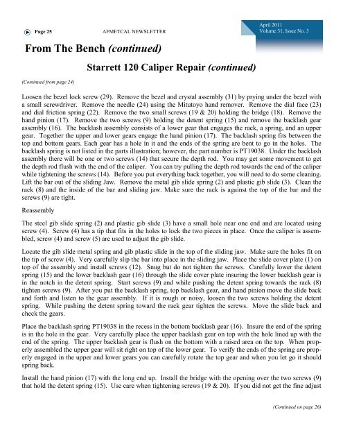
Page 25<strong>AFMETCAL</strong> NEWSLETTERApril 2011Volume 31, Issue No. 3From The Bench (continued)(Continued from page 24)Starrett 120 Caliper Repair (continued)Loosen the bezel lock screw (29). Remove the bezel and crystal assembly (31) by prying under the bezel witha small screwdriver. Remove the needle (24) using the Mitutoyo hand remover. Remove the dial face (23)and dial friction spring (22). Remove the two small screws (19 & 20) holding the bridge (18). Remove thehand pinion (17). Remove the two screws (9) holding the detent spring (15) and remove the backlash gearassembly (16). The backlash assembly consists of a lower gear that engages the rack, a spring, and an uppergear. Together the upper and lower gears engage the hand pinion (17). The backlash spring fits between thetop and bottom gears. Each gear has a hole in it and the ends of the spring are bent to go in the holes. Thebacklash spring is not listed in the parts illustration; however, the part number is PT19038. Under the backlashassembly there will be one or two screws (14) that secure the depth rod. You may get some movement to getthe depth rod flush with the end of the caliper. You can try pulling the depth rod towards the end of the caliperwhile tightening the screws (14). Before you put everything back together, you will need to do some cleaning.Lift the bar out of the sliding Jaw. Remove the metal gib slide spring (2) and plastic gib slide (3). Clean therack (8) and the inside of the bar and sliding jaw. Make sure the rack is against the top of the bar and thescrews (9) are tight.ReassemblyThe steel gib slide spring (2) and plastic gib slide (3) have a small hole near one end and are located usingscrew (4). Screw (4) has a tip that fits in the holes to lock the two pieces in place. Once the caliper is assembled,screw (4) and screw (5) are used to adjust the gib slide.Locate the gib slide metal spring and gib plastic slide in the top of the sliding jaw. Make sure the holes fit onthe tip of screw (4). Very carefully slip the bar into place in the sliding jaw. Place the slide cover plate (1) ontop of the assembly and install screws (12). Snug but do not tighten the screws. Carefully lower the detentspring (15) and the lower backlash gear (16) through the slide cover plate insuring the lower backlash gear isin the notch in the detent spring. Start screws (9) and while pushing the detent spring towards the rack (8)tighten screws (9). After you put the backlash spring, top backlash gear, and hand pinion move the slide backand forth and listen to the gear assembly. If it is rough or noisy, loosen the two screws holding the detentspring. While pushing the detent spring toward the rack gear tighten the screws. Move the slide back andcheck the gears.Place the backlash spring PT19038 in the recess in the bottom backlash gear (16). Insure the end of the springis in the hole in the gear. Very carefully place the upper backlash gear on top with the hole lined up with theend of the spring. The upper backlash gear is flush on the bottom with a raised area on the top. When properlyassembled the upper gear will sit right on top of the lower gear. To verify the ends of the spring are properlyengaged in the upper and lower gears you can carefully rotate the top gear and when you let go it shouldspring back.Install the hand pinion (17) with the long end up. Install the bridge with the opening over the two screws (9)that hold the detent spring (15). Use care when tightening screws (19 & 20). If you did not get the fine adjust(Continued on page 26)


