

SSP 336 The Catalytic Coated Diesel Particulate Filter - Volkspage
SSP 336 The Catalytic Coated Diesel Particulate Filter - Volkspage
SSP 336 The Catalytic Coated Diesel Particulate Filter - Volkspage

Create successful ePaper yourself
Turn your PDF publications into a flip-book with our unique Google optimized e-Paper software.
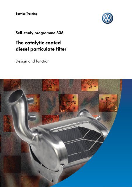
Service Training<br />
Self-study programme <strong>336</strong><br />
<strong>The</strong> catalytic coated<br />
diesel particulate filter<br />
Design and function
<strong>The</strong> reduction of particulate emissions from diesel<br />
engines is a great challenge in this day and age.<br />
In addition to engine measures, exhaust gas treatment<br />
is of particular importance to help achieve this.<br />
<strong>The</strong> particulate filter is an effective method to remove<br />
carbon soot particles that are inherent in diesel<br />
emissions.<br />
<strong>The</strong> most common filter systems comprise of an<br />
oxidisation catalyst and a particulate filter. On the<br />
catalytic coated particulate filter from Volkswagen,<br />
the catalyst and filter have been combined to form<br />
one single unit. With this particulate filter system, the<br />
particulates can be burnt off continually without the<br />
addition of a fuel additive, thanks to the design and<br />
installation position close to the engine.<br />
S<strong>336</strong>_231<br />
NEW<br />
Important<br />
Note<br />
This self-study programme shows the design and<br />
function of new developments!<br />
<strong>The</strong> contents will not be updated.<br />
Please always refer to the relevant Service Literature<br />
for all inspection, adjustment and repair instructions.<br />
2
Contents<br />
Introduction . . . . . . . . . . . . . . . . . . . . . . . . . . . . . . . . . . .4<br />
Design and function . . . . . . . . . . . . . . . . . . . . . . . . . . . 12<br />
System overview . . . . . . . . . . . . . . . . . . . . . . . . . . . . . .23<br />
Sensors and actuators. . . . . . . . . . . . . . . . . . . . . . . . . .24<br />
Function diagram . . . . . . . . . . . . . . . . . . . . . . . . . . . . .32<br />
System limits . . . . . . . . . . . . . . . . . . . . . . . . . . . . . . . . .33<br />
Test your knowledge . . . . . . . . . . . . . . . . . . . . . . . . . . 35<br />
3
Introduction<br />
General<br />
During combustion of diesel fuel, all sorts of different<br />
deposits are built up. Those that can be perceived<br />
directly as exhaust components on a cold engine are<br />
non or partly oxidised hydrocarbons in droplet form<br />
as white or blue smoke and strong smelling aldehyde.<br />
In addition to harmful gaseous substances, particles<br />
of solid substances are emitted with the emissions<br />
from diesel engines, which have been included under<br />
the main heading of particulates with regards to<br />
substances that are damaging to health and the<br />
environment.<br />
<strong>Catalytic</strong> coated<br />
diesel particulate filter<br />
S<strong>336</strong>_233<br />
Volkswagen follows a long-term strategy with the aim<br />
of reducing exhaust emissions – not only in the area<br />
of diesel particulates but also for all other emissions<br />
components, such as hydrocarbons and nitrogen<br />
oxides. Some years ago, Volkswagen undertook tough<br />
measures on a continual basis to optimise the internal<br />
combustion processes and to reduce the emission of<br />
carbon soot particles from diesel engines.<br />
And with success: In 1999, Volkswagen was able to<br />
offer the Lupo 3L TDI on the market as the first vehicle<br />
to meet the strict Euro 4 exhaust emissions standard –<br />
six years before the standard was established as a<br />
legal requirement in 2005.<br />
Volkswagen played an important role in driving on<br />
the development for clean diesel fuel and thereby<br />
faced the responsibility of protecting the environment.<br />
Examples of this are the efficient, economical and low<br />
noise generating TDI technology and also the unit<br />
injector system. Volkswagen will continue to selectively<br />
improve internal combustion processes in the future to<br />
further bring down fuel consumption and reduce<br />
emissions directly at source. In addition, Volkswagen<br />
will enhance these efforts step-by-step by the<br />
introduction of diesel particulate filter systems.<br />
4
<strong>The</strong> exhaust gas<br />
Emissions standards<br />
In the Republic of Germany, across Europe and throughout the world, laws have been passed in recent years to<br />
reduce the emission of harmful substances in the air. In Europe, the emissions standards are categorised from EU1<br />
to EU4. <strong>The</strong>se prescribe emission limits to the automobile industry for type approval of new vehicle models.<br />
EU3<br />
From the year 2000, newly registered vehicles have<br />
to fulfil emissions standard EU3.<br />
It differs from its predecessor EU2 by more stringent<br />
conditions on the test bed and by a reduction in the<br />
limit values.<br />
EU4<br />
<strong>The</strong> EU4 standard will come into force in 2005 and<br />
will supersede EU3. <strong>The</strong> consequences are a further<br />
reduction in permissible limit values.<br />
Even now, more than 65 percent of all newly<br />
registered Volkswagens with a diesel engine fulfil<br />
emissions standard EU4 in Germany.<br />
g/km<br />
0.8<br />
0.6<br />
Permissible limit values for diesel engines<br />
0.64<br />
0.50<br />
0.56<br />
0.50<br />
0.4<br />
0.30<br />
0.25<br />
0.2<br />
0.05 0.025<br />
EU3 EU4 EU3 EU4 EU3 EU4 EU3 EU4<br />
CO<br />
Carbon monoxide<br />
HC + NO X<br />
Hydrocarbons and<br />
nitrogen oxides<br />
NO X<br />
Nitrogen oxides<br />
PM<br />
Carbon soot particles<br />
S<strong>336</strong>_026<br />
Outlook<br />
In the future, the more stringent EU5 standard will come into force. <strong>The</strong> limit values for this standard have as yet not<br />
been established, but acceptable emission levels will be lowered even further. <strong>The</strong>re are plans to markedly reduce<br />
the particulate limit value for diesel passenger vehicles even further. <strong>The</strong>refore, all diesel passenger vehicles must<br />
be fitted with a particulate filter in the future.<br />
5
Introduction<br />
Harmful substances caused by combustion<br />
<strong>The</strong> harmful substances, and particulate emissions in particular, are influenced in a diesel engine by the<br />
combustion process. This process is affected by many factors relating to the construction, the fuel itself and the<br />
atmosphere.<br />
<strong>The</strong> following illustration shows an overview of the inlet and exhaust components of a diesel engine during<br />
combustion.<br />
Injected fuel:<br />
HC Hydrocarbons<br />
S Sulphur<br />
Intake air:<br />
O 2 Oxygen<br />
N 2 Nitrogen<br />
H 2 O Water<br />
(humidity)<br />
approx.<br />
67%<br />
Exhaust gas:<br />
O 2 Oxygen<br />
N 2 Nitrogen<br />
H 2 O Water<br />
CO 2 Carbon dioxide<br />
N 2<br />
approx.<br />
12%<br />
SO 2<br />
CO 2 approx.<br />
11%<br />
PM<br />
H 2 O<br />
HC<br />
approx.<br />
O 2 0.3%<br />
NO X<br />
approx.<br />
10%<br />
CO<br />
S<strong>336</strong>_108<br />
CO Carbon monoxide<br />
HC Hydrocarbons<br />
SO 2 Sulphur dioxide<br />
NOx Nitrogen oxide<br />
PM Carbon soot particles<br />
(PM = particulate matter)<br />
With regards to the damaging effect on the<br />
environment and health, the emissions from a diesel<br />
engine have various components that require different<br />
analyses.<br />
Those components that are already present in the<br />
atmosphere (oxygen, nitrogen and water) can be<br />
categorised as safe.<br />
Carbon dioxide, which is present in the atmosphere as<br />
a natural gas, is at the limit between safe and harmful<br />
due to its categorisation. It may not be poisonous,<br />
but in higher concentrations it can contribute towards<br />
the greenhouse effect.<br />
Carbon monoxide, hydrocarbons, sulphur dioxide,<br />
nitrogen oxide and particulates are categorised as<br />
harmful.<br />
6
Harmful substances in the exhaust gas<br />
CO<br />
Carbon<br />
monoxide<br />
Carbon monoxide (CO) is generated from oxygen<br />
deficiency as a result of the incomplete combustion of<br />
fuels containing carbon. It is a gas and has no colour,<br />
smell or taste.<br />
S<strong>336</strong>_014<br />
HC<br />
Hydrocarbons<br />
Hydrocarbons cover a wide range of different<br />
compounds (for example C 6 H 6 , C 8 H 18 ), which occur<br />
as a result of incomplete combustion.<br />
S<strong>336</strong>_016<br />
SO 2<br />
Sulphur dioxide<br />
Sulphur dioxide is generated by the combustion of<br />
fuel containing sulphur. It is a gas without colour but<br />
with a pungent smell. <strong>The</strong> amount of sulphur added to<br />
fuel is decreasing.<br />
S<strong>336</strong>_018<br />
NO x<br />
Nitrogen oxides<br />
Nitrogen oxides (for example NO, NO 2 , . . .)<br />
are generated by high pressure, high temperature<br />
and excessive oxygen during combustion in the<br />
engine.<br />
S<strong>336</strong>_020<br />
Carbon soot particles<br />
If there is an oxygen deficiency the result is a build up<br />
of carbon soot particles from incomplete combustion.<br />
S<strong>336</strong>_022<br />
7
Introduction<br />
<strong>The</strong> particulates<br />
<strong>Particulate</strong>s is a term that covers all particles, solid or<br />
liquid, that are generated from friction, breakdown of<br />
components, erosion, condensation and incomplete<br />
combustion.<br />
<strong>The</strong>se processes create particulates in different<br />
shapes, sizes and structures.<br />
<strong>Particulate</strong>s have the same character as harmful<br />
substances in the air if, due to their small dimensions,<br />
they can float around in gaseous substances and<br />
damage organisms.<br />
<strong>The</strong> carbon soot particles<br />
Carbon soot particles are generated from the<br />
combustion process in a diesel engine. Carbon soot<br />
particles are microscopic balls of carbon with a<br />
diameter of about 0.05 µm. <strong>The</strong>ir core consists of pure<br />
carbon. Around the core are deposits of different<br />
hydrocarbon compounds, metal oxides and sulphur.<br />
Some hydrocarbon compounds are categorised as<br />
potentially hazardous to health.<br />
<strong>The</strong> exact composition of carbon soot particles<br />
depends on the engine technology, the conditions of<br />
use and the type of fuel.<br />
Hydrocarbons<br />
SO 4 (sulphate)<br />
Carbon<br />
Sulphur and metal oxides<br />
H 2 O (water)<br />
S<strong>336</strong>_182<br />
8
Cause of carbon soot particles<br />
<strong>The</strong> build up of carbon soot particles in a diesel engine depends on the individual processes of diesel combustion,<br />
such as air intake, injection, flame spread.<br />
<strong>The</strong> combustion quality depends on how well the fuel is mixed with the air.<br />
<strong>The</strong> mixture in some areas of the combustion chamber could be too rich because not enough oxygen is present.<br />
Combustion will then be incomplete and carbon soot particles will be formed.<br />
S<strong>336</strong>_013<br />
Typical particle of carbon soot caused by combustion<br />
in a diesel engine<br />
<strong>The</strong> mass and number of particles are therefore<br />
affected generally by the quality of the engine<br />
combustion process. With high injection pressure and<br />
an injection pattern based on the requirements of the<br />
engine, the unit injector system ensures efficient<br />
combustion and thereby reduces the formation of<br />
carbon soot particles during the combustion process.<br />
High injection pressure and associated fine<br />
atomisation of the fuel, however, does not necessarily<br />
lead to smaller particles.<br />
Tests have shown that the difference in particle sizes in<br />
the exhaust gas is very similar regardless of the<br />
combustion principle of the engine, whether swirl<br />
chamber, common rail or unit injector technology.<br />
9
Introduction<br />
<strong>The</strong> measures to reduce particulates<br />
<strong>The</strong> reduction of exhaust emissions in a diesel engine is an important aim in further development.<br />
<strong>The</strong>re is a range of different technical solutions to reduce exhaust emissions.<br />
Here, a difference is made between internal and external engine measures.<br />
Internal engine measures<br />
A reduction in emissions can be achieved by<br />
measures to the internal workings of an engine.<br />
Effective optimisation of the combustion process can<br />
ensure that harmful substances are not produced at<br />
all.<br />
Examples of internal engine measures are:<br />
● the design of the inlet and exhaust ports for<br />
optimal flow properties,<br />
● high injection pressures, for example from<br />
unit injector technology,<br />
● the combustion chamber design, for example<br />
reduction in the size of the area where harmful<br />
substances are produced, design of the piston<br />
crown.<br />
S<strong>336</strong>_045<br />
10
External engine measures<br />
<strong>The</strong> release of carbon soot particles that are produced during combustion can be prevented by external engine<br />
measures. This can be seen as the reduction of carbon soot particles by means of a particulate filter system.<br />
To do this, it is necessary to differentiate between two systems – the diesel particulate filter with additive and the<br />
catalytic coated diesel particulate filter. On the next few pages the design and function of just the catalytic coated<br />
diesel particulate filter will be described.<br />
System with additive<br />
This system is used on vehicles where the particulate filter is installed away from the engine. Due to the distance the<br />
exhaust gas has to make from the engine to the particulate filter, the required ignition temperature for combustion<br />
of the particulates can only be reached with the introduction of an additive.<br />
750°C<br />
Temperature of exhaust gas<br />
in regeneration mode<br />
Oxidisation catalyst<br />
Particle filter<br />
620°C 500°C<br />
S<strong>336</strong>_142<br />
<strong>Catalytic</strong> coated system<br />
This system is used on vehicles where the particulate filter is installed close to the engine. Due to the short distance<br />
exhaust gas has to take from the engine to the particulate filter, the temperature of the exhaust gas is sufficiently<br />
high enough to burn off the carbon soot particles.<br />
Temperature of exhaust gas<br />
in regeneration mode<br />
750°C<br />
<strong>Particulate</strong> filter with integrated<br />
oxidisation catalyst<br />
620°C<br />
S<strong>336</strong>_144<br />
11
Design and function<br />
<strong>The</strong> system of the catalytic coated diesel particulate filter<br />
Shown in the overview below are the components of the diesel particulate filter system.<br />
4<br />
1 2<br />
3<br />
10<br />
5<br />
6<br />
7<br />
8<br />
9<br />
11<br />
12<br />
S<strong>336</strong>_030<br />
1 Control unit in dash panel insert J285<br />
2 Engine control unit<br />
3 Air mass meter<br />
4 <strong>Diesel</strong> engine<br />
5 Temperature sender before turbocharger G507<br />
6 Turbocharger<br />
7 Temperature sender before particulate filter G506<br />
8 Lambda probe G39<br />
9 <strong>Particulate</strong> filter<br />
10 Exhaust gas pressure sensor 1 G450<br />
11 Temperature sender after particulate filter G527<br />
12 Silencer<br />
<strong>The</strong> overview shows a system with single exhaust pipe. On multi-pipe exhaust systems the particulate<br />
filter and the sensors on the exhaust system are installed for each set of cylinders.<br />
12
<strong>The</strong> particle filter<br />
<strong>The</strong> catalytic coated diesel particulate filter is located<br />
in the exhaust system after the turbocharger,<br />
within close proximity of the engine.<br />
Two components, the oxidisation catalyst and the<br />
particulate filter, have been combined to form one<br />
unit, the catalytic coated diesel particulate filter.<br />
It joins the functions of the oxidisation catalyst and the<br />
diesel particulate filter in one single component.<br />
<strong>Catalytic</strong> coated<br />
diesel particulate filter<br />
S<strong>336</strong>_039<br />
Oxidisation catalyst<br />
Particle filter<br />
Oxidisation catalyst<br />
Particle filter<br />
S<strong>336</strong>_212<br />
<strong>Catalytic</strong> coated<br />
diesel particulate filter<br />
<strong>Catalytic</strong> coated<br />
diesel particulate filter<br />
As a diesel particulate filter it filters out the carbon soot particles from the exhaust gas. In its function as oxidisation<br />
catalyst, it cleans the exhaust gas of hydrocarbons (HC) and carbon monoxide (CO). <strong>The</strong>y are converted into water<br />
(H 2 O) and carbon dioxide (CO 2 ).<br />
Detailed information about oxidisation catalysts can be found in self-study programme no. 124<br />
"<strong>Diesel</strong> engine catalysts".<br />
13
Design and function<br />
Design<br />
<strong>The</strong> diesel particulate filter comprises of a honeycomb ceramic matrix made from silicon carbide, which can be<br />
found in a metal housing. <strong>The</strong> ceramic matrix itself has many small channels that run parallel to each other<br />
and are alternately connected. In this way, inlet and outlet channels are created that are separated<br />
by filter walls.<br />
Soot particles<br />
Outlet channel<br />
Honeycomb<br />
ceramic matrix<br />
<strong>Filter</strong> wall<br />
Inlet channel<br />
S<strong>336</strong>_038<br />
S<strong>336</strong>_154<br />
Metal housing<br />
Soot particles in<br />
inlet channel<br />
Catalyst<br />
platinum<br />
Silicon<br />
carbide body<br />
<strong>The</strong> filter walls made from silicon carbide are porous.<br />
<strong>The</strong> silicon carbide body is coated with a mixture of<br />
aluminium oxide and ceroxide.<br />
This mixture serves as a carrier layer for the<br />
catalytic converter. <strong>The</strong> carrier layer is coated with a<br />
precious metal, platinum, which acts as the catalyst.<br />
A catalyst is a substance that promotes or hinders<br />
a chemical reaction without changing itself.<br />
Outlet channel<br />
S<strong>336</strong>_204<br />
Carrier layer<br />
(aluminium oxide/<br />
ceroxide)<br />
Function<br />
Since the channels are sealed alternately in the direction of flow from the inlet and outlet side, the carbon soot<br />
contaminated exhaust gas must flow through the porous filter walls made from silicon carbide. When this happens,<br />
the carbon soot particles and not the gaseous components are retained in the inlet channels.<br />
14
<strong>The</strong> coated zones in the diesel particulate filter<br />
<strong>The</strong> diesel particulate filter requires a certain length in<br />
order to provide a large storage volume for the<br />
carbon soot. In addition, it must be coated with a<br />
certain amount of platinum in order to attain the<br />
desired catalytic effect.<br />
<strong>The</strong> catalytic coating of the diesel particulate filter is<br />
separated into zones across the length of the filter.<br />
Front zone<br />
Rear zone<br />
S<strong>336</strong>_010<br />
In the front zone there is a large quantity of platinum and in the rear zone there is less platinum.<br />
<strong>The</strong> following are advantages from the zone-like coating:<br />
● In normal operating mode of the engine the diesel particulate filter heats up quickly in the front area. Due to the<br />
high concentration of platinum in this front zone of the catalyst, the filter has a very fast catalytic effect. In other<br />
words, the diesel particulate filter responds quickly.<br />
● In regeneration mode, the rear area of the diesel particulate filter becomes very hot as the carbon soot is burnt<br />
off. Due to these high temperatures the platinum gets broken down over a period of time.<br />
<strong>The</strong>refore, the expensive raw material is not used as intensively in the rear zone.<br />
● A further reason for reduced use of platinum in the rear zone is ageing of the diesel particulate filter.<br />
During operation, more and more deposits are built up in the rear area from combustion, which impair the<br />
catalytic effectiveness of the platinum.<br />
Regeneration<br />
<strong>The</strong> diesel particulate filter must be cleaned of the particles of carbon soot regularly to prevent it from becoming<br />
blocked and its function thereby being affected. During the regeneration phase, the particulates that have<br />
accumulated in the particulate filter are burnt off (oxidised). With regeneration of the catalytic coated particulate<br />
filter, passive regeneration and active regeneration are separated. <strong>The</strong>re are no signs to the driver that<br />
regeneration is occurring.<br />
15
Design and function<br />
Passive regeneration<br />
With passive regeneration, the carbon soot particles are burnt off continually without intervention from the engine<br />
management system. <strong>The</strong> particulate filter is positioned in close proximity to the engine. This assures that exhaust<br />
gas temperatures of 350-500 °C are reached on motorways, for example. <strong>The</strong> carbon soot particles are thereby<br />
converted into carbon dioxide by a reaction with nitrogen oxide. This gradual process occurs slowly and continually<br />
through the platinum coating, which works as a catalyst.<br />
Silicon<br />
carbide body<br />
Carrier layer<br />
(aluminium oxide/<br />
ceroxide)<br />
Inlet channel<br />
Platinum<br />
<strong>Filter</strong> wall<br />
Outlet channel<br />
S<strong>336</strong>_184<br />
Function<br />
From the nitrogen oxides present in the exhaust gas (NO X ) and oxygen (O 2 ), nitrogen dioxide (NO 2 ) is<br />
produced via the platinum coating.<br />
NO X + O 2 reacts to NO 2<br />
<strong>The</strong> nitrogen dioxide (NO 2 ) reacts with the carbon (C) of the carbon soot particles. As a result,<br />
carbon monoxide (CO) and nitrogen monoxide (NO) are formed.<br />
NO 2 + C reacts to CO + NO<br />
<strong>The</strong> carbon monoxide (CO) and nitrogen monoxide (NO) combine with oxygen (O 2 ) and form nitrogen<br />
dioxide (NO 2 ) and carbon dioxide (CO 2 ).<br />
CO + NO + O 2 reacts to NO 2 + CO 2<br />
16
Active regeneration<br />
With active regeneration, the carbon soot particles are burnt off through a targeted increase in the exhaust gas<br />
temperature by the engine management system. In urban traffic with low loads on the engine, the exhaust gas<br />
temperatures for passive regeneration of the particulate filter are too low. Since the carbon soot particles cannot<br />
be broken down, deposits build up in the filter. As soon as a certain level of carbon soot deposits is reached in the<br />
filter, active regeneration is initiated by the engine management system. This process lasts for approximately<br />
10 minutes. <strong>The</strong> carbon soot particles are burnt off to carbon dioxide at an exhaust gas temperature of 600-650 °C.<br />
Carrier layer<br />
(aluminium<br />
oxide/ceroxide)<br />
Silicon carbide<br />
body<br />
Inlet channel<br />
Platinum<br />
<strong>Filter</strong> wall<br />
Outlet channel<br />
S<strong>336</strong>_186<br />
Function<br />
With active regeneration, the carbon soot particles are burnt off by high exhaust gas temperatures. When this<br />
happens, the carbon from the soot particles oxidises with oxygen and forms carbon dioxide.<br />
C + O 2 reacts to CO 2<br />
17
Design and function<br />
Function of active regeneration<br />
<strong>The</strong> carbon soot particles are retained in the inlet channels. <strong>The</strong> engine control unit can detect the level of carbon<br />
soot in the particulate filter by evaluating the signals from the air mass meter, the temperature sender before and<br />
after particulate filter and the exhaust gas pressure sensor 1.<br />
<strong>Particulate</strong> filter empty<br />
Air mass meter G70<br />
Signals to<br />
engine control unit<br />
Temperature sender<br />
before particulate<br />
filter G506<br />
Exhaust gas pressure sensor 1 G450<br />
Temperature sender<br />
after particulate filter<br />
G527<br />
S<strong>336</strong>_042<br />
<strong>Particulate</strong> filter empty = low resistance to flow<br />
<strong>Particulate</strong> filter full<br />
Air mass meter G70<br />
Signals to<br />
engine control unit<br />
Temperature sender<br />
before particulate<br />
filter G506<br />
Exhaust gas pressure sensor 1 G450<br />
Temperature sender<br />
after particulate filter<br />
G527<br />
S<strong>336</strong>_044<br />
<strong>Particulate</strong> filter full = high resistance to flow<br />
When the carbon soot level reaches a predetermined limit, the engine management system initiates active<br />
regeneration.<br />
18
Engine management during initiation of active regeneration<br />
From the flow resistance of the filter, the engine control unit can detect the level of carbon soot deposit in the filter.<br />
A high flow resistance indicates that the filter is in danger of becoming blocked. <strong>The</strong> engine control unit initiates an<br />
active regeneration process. To do this:<br />
● exhaust gas recirculation is switched off to<br />
raise the combustion temperature,<br />
S<strong>336</strong>_124<br />
● an extended injection period is initiated, after a<br />
period of main injection with reduced quantity at<br />
35° crankshaft angle after TDC, in order to increase<br />
the exhaust gas temperature,<br />
S<strong>336</strong>_126<br />
● the supply of intake air is regulated by an<br />
electric throttle valve and<br />
S<strong>336</strong>_120<br />
● the charge air pressure is adapted so that<br />
the torque during regeneration does not change<br />
noticeably by the driver.<br />
S<strong>336</strong>_122<br />
<strong>The</strong>se measures lead to a targeted, brief increase in the exhaust gas temperature to approximately 600 °C to<br />
650 °C. In this temperature range, the collective carbon soot oxidises to carbon dioxide. After this active<br />
regeneration period, the particulate filter is ready for operation again and can begin filtering carbon soot out<br />
of the exhaust gas.<br />
19
Design and function<br />
Level of carbon deposit in particulate filter<br />
<strong>The</strong> level of carbon deposit in the particulate filter is constantly monitored by the engine control unit,<br />
which calculates the flow resistance of the filter. To determine the flow resistance, the exhaust gas volume before the<br />
particulate filter is compared with the pressure difference before and after the particulate filter and recorded<br />
as a ratio.<br />
Pressure difference<br />
<strong>The</strong> pressure difference of the air flow before and after particulate filter is calculated by exhaust gas pressure<br />
sensor 1.<br />
Exhaust gas volume<br />
<strong>The</strong> exhaust gas volume is calculated by the engine control unit from the air mass in the exhaust manifold<br />
and the exhaust gas temperature before the particulate filter. <strong>The</strong> mass of exhaust gas is roughly equivalent to the<br />
mass of air in the intake manifold, which is calculated by the air mass meter. <strong>The</strong> volume of exhaust gas depends<br />
on the respective temperature. <strong>The</strong> temperature is calculated from the senders before and after particulate filter.<br />
Using the exhaust gas temperature reading, the engine control unit can calculate the exhaust gas volume from the<br />
mass of air in the exhaust gas.<br />
Flow resistance of particulate filter<br />
300<br />
Pressure difference ∆p (mbar)<br />
250<br />
200<br />
150<br />
100<br />
50<br />
0<br />
0 100 200 300 400 500 600 700<br />
Volume (m 3 /h)<br />
S<strong>336</strong>_156<br />
<strong>Diesel</strong> particulate filter:<br />
Full<br />
Empty<br />
Defective<br />
<strong>The</strong> engine control unit creates a ratio from the pressure difference and the volume of exhaust gas and can thus<br />
calculate the flow resistance of the particulate filter. From the flow resistance, the engine control unit can detect the<br />
level of carbon soot deposit.<br />
20
Extended injection period at overrun<br />
In heavy urban traffic with strong changes in engine load and a high percentage of overrun operation, particular<br />
measures are necessary for cleansing of the filter. Normally, no more fuel is injected in the cylinders at overrun,<br />
therefore the exhaust gas cannot reach the necessary temperature for purposes of particulate filter regeneration.<br />
A small amount of fuel is injected at overrun,<br />
at approx. 35° crankshaft angle after TDC.<br />
S<strong>336</strong>_128<br />
Since there is no main injection at TDC, the fuel does<br />
not combust but vaporises.<br />
S<strong>336</strong>_130<br />
This fuel vapour combusts in the particulate filter.<br />
<strong>The</strong> heat generated as a result means the required<br />
temperature of the exhaust gas is assured for<br />
regeneration of the particulate filter.<br />
S<strong>336</strong>_202<br />
<strong>The</strong> temperature sender after particulate filter<br />
monitors the exhaust gas temperature after<br />
particulate filter. This regulates the extended injection<br />
volume at overrun.<br />
S<strong>336</strong>_200<br />
21
Design and function<br />
<strong>The</strong> injection cams<br />
On diesel engines with unit injector technology and diesel particulate filter, the contour of the injection cam has<br />
been modified for the extended injection period.<br />
Compared to an engine without diesel particulate filter, the injection cam is designed so the downwards motion of<br />
the pump plunger is longer. In this way, there is enough stroke available to allow extended injection at a later stage.<br />
Rocker roller<br />
finger<br />
Ball head pins<br />
Injection cams<br />
Pump plunger<br />
Plunger spring<br />
S<strong>336</strong>_216<br />
Contour of cam on diesel engines with unit injector system and no diesel particulate filter<br />
Contour of cam on diesel engines with unit injector system and diesel particulate filter<br />
Please refer to setting specifications in workshop manual when installing unit injector.<br />
22
System overview<br />
CAN bus<br />
Control unit with display in dash<br />
panel insert J285<br />
Temperature sender before<br />
particulate filter G506<br />
<strong>Diesel</strong> particulate filter<br />
warning lamp K231<br />
Temperature sender before<br />
turbocharger G507<br />
Preglow control<br />
lamp K29<br />
Temperature sender after<br />
particulate filter G527<br />
<strong>Diesel</strong> direct injection system<br />
control unit J248<br />
Exhaust gas pressure<br />
sensor 1 G450<br />
Lambda probe heater Z19<br />
Lambda probe G39<br />
Diagnosis connector<br />
Unit injector valves N240-N243<br />
Air mass meter G70<br />
Solenoid valve block with:<br />
Exhaust gas recirculation valve N18<br />
Charge pressure control solenoid valve N75<br />
Fuel gauge sender G<br />
S<strong>336</strong>_106<br />
Intake manifold flap motor V157<br />
23
Sensors and actuators<br />
Exhaust gas pressure sensor 1 G450<br />
Signal application<br />
Exhaust gas pressure sensor 1 measures the pressure<br />
difference in the flow of exhaust gas before and after<br />
the particulate filter. <strong>The</strong> signal from the exhaust gas<br />
pressure sensor, the signal from the temperature<br />
sender before and after particulate filter and the<br />
signal from the air mass meter form an inseparable<br />
unit during calculation of the level of carbon soot<br />
deposit in the particulate filter.<br />
S<strong>336</strong>_048<br />
Effects of signal failure<br />
In the event of signal failure from the exhaust gas<br />
pressure sensor, the particulate filter regeneration<br />
cycle will be based on the distance travelled or the<br />
number of hours in operation. This cycle for<br />
particulate filter regeneration, however,<br />
is not effective over a long period of time.<br />
After a predetermined number of cycles, the diesel<br />
particulate filter warning lamp will light up and<br />
the preglow control lamp will then flash in the dash<br />
panel insert. This informs the driver that the vehicle<br />
must be driven to a workshop.<br />
Design<br />
Exhaust gas pressure sensor 1 features two pressure<br />
connections. Leading from one is a pressure line to the<br />
flow of exhaust gas before particulate filter and from<br />
the other to the flow of exhaust gas after particulate<br />
filter.<br />
Membrane with<br />
piezo elements<br />
Signal to<br />
control unit<br />
Installed in the sender is a membrane with piezo<br />
elements, which effect the respective exhaust gas<br />
pressures.<br />
S<strong>336</strong>_050<br />
Pressure before filter<br />
Pressure after filter<br />
24
This is how it works:<br />
<strong>Particulate</strong> filter empty<br />
Piezo<br />
elements<br />
S<strong>336</strong>_090<br />
If the particulate filter has a very low carbon soot<br />
deposit level, the pressure before and after the filter is<br />
almost the same.<br />
<strong>The</strong> membrane with the piezo elements is in a position<br />
of rest.<br />
S<strong>336</strong>_160<br />
Pressure before filter = pressure after filter<br />
<strong>Particulate</strong> filter full<br />
S<strong>336</strong>_162<br />
Pressure before filter > pressure after filter<br />
S<strong>336</strong>_092<br />
If there is a build up of carbon soot in the particulate<br />
filter, the exhaust gas pressure rises before the filter<br />
due to a lower flow volume.<br />
<strong>The</strong> exhaust gas pressure behind the filter remains<br />
almost the same. <strong>The</strong> membrane changes its shape<br />
depending on the difference in pressure.<br />
This deformation alters the electrical resistance of the<br />
piezo elements, which are connected to form a test<br />
bridge. <strong>The</strong> output voltage of this test bridge is<br />
processed, amplified and sent by the sensor<br />
electronics as a signal voltage to the engine control<br />
unit. From this signal, the engine control unit<br />
calculates the level of carbon soot deposit in the<br />
particulate filter and initiates regeneration to clean<br />
the filter.<br />
<strong>The</strong> level of carbon soot deposit in the particulate filter can be checked using vehicle diagnosis,<br />
testing and information system VAS 5051 in a measured value block as "particulate load coefficient".<br />
25
Sensors and actuators<br />
Temperature sender before particulate filter G506<br />
S<strong>336</strong>_100<br />
S<strong>336</strong>_187<br />
<strong>The</strong> temperature sender before particulate filter is a<br />
PTC sensor. On a sensor with PTC (positive<br />
temperature coefficient), resistance rises as<br />
temperature increases.<br />
It can be found in the exhaust system before the diesel<br />
particulate filter. <strong>The</strong>re it measures the temperature<br />
of the exhaust gas.<br />
Signal application<br />
Using the signal from the temperature sender before<br />
and after particulate filter, the engine control unit<br />
calculates the exhaust gas volume in order to<br />
determine the level of carbon soot deposit in the<br />
particulate filter.<br />
<strong>The</strong> signals from the temperature senders before and<br />
after particulate filter, the signal from the air mass<br />
meter and the signal from the exhaust gas pressure<br />
sensor form an inseparable unit during calculation of<br />
the level of carbon soot deposit in the particulate<br />
filter.<br />
Effects of signal failure<br />
In the event of signal failure from the temperature<br />
sender before particulate filter, the particulate filter<br />
regeneration cycle will be based on the distance<br />
travelled or the number of hours in operation.<br />
This cycle for particulate filter regeneration, however,<br />
is not effective over a long period of time. After a<br />
predetermined number of cycles, the diesel<br />
particulate filter warning lamp will light up and then<br />
the preglow control lamp will flash in the dash panel<br />
insert. This informs the driver that the vehicle must be<br />
driven to a workshop.<br />
Furthermore, the signal is used as a form of<br />
component protection to protect the particulate filter<br />
against high exhaust gas temperatures.<br />
26
Temperature sender after particulate filter G527<br />
S<strong>336</strong>_100<br />
S<strong>336</strong>_189<br />
<strong>The</strong> temperature sender after particulate filter is a<br />
PTC sensor.<br />
It can be found in the exhaust system after the diesel<br />
particulate filter. <strong>The</strong>re it measures the temperature<br />
of the exhaust gas.<br />
Signal application<br />
<strong>The</strong> engine control unit uses the signal from the<br />
temperature sender after particulate filter to regulate<br />
the injection volume for extended injection at overrun.<br />
<strong>The</strong> higher the exhaust gas temperature after<br />
particulate filter, the lower the injection volume.<br />
<strong>The</strong> signal from the temperature sender is used as a<br />
form of component protection to safeguard the<br />
particulate filter against high exhaust gas<br />
temperatures.<br />
Effects of signal failure<br />
In the event of signal failure from the temperature<br />
sender after particulate filter, the particulate filter<br />
regeneration cycle will be based on the distance<br />
travelled or the number of hours in operation.<br />
This cycle for particulate filter regeneration, however,<br />
is not effective over a long period of time. After a<br />
predetermined number of cycles, the diesel<br />
particulate filter warning lamp will light up and then<br />
the preglow control lamp will flash in the dash panel<br />
insert. This informs the driver that the vehicle must be<br />
driven to a workshop.<br />
27
Sensors and actuators<br />
Temperature sender before turbocharger G507<br />
S<strong>336</strong>_096<br />
S<strong>336</strong>_215<br />
<strong>The</strong> temperature sender before turbocharger is a PTC<br />
sensor. It can be found in the exhaust system before<br />
the turbocharger. <strong>The</strong>re is measures the temperature<br />
of the exhaust gas.<br />
Signal application<br />
<strong>The</strong> engine control unit requires the signal from the<br />
temperature sender before turbocharger to calculate<br />
start of injection and the quantity of extended<br />
injection for regeneration. In this way, the required<br />
temperature increase for combustion of the carbon<br />
soot particles is reached.<br />
In addition, the signal is used to protect the<br />
turbocharger against excessively high temperatures<br />
during regeneration.<br />
Effects of signal failure<br />
In the event of failure from the temperature sender<br />
before turbocharger, the turbocharger can no longer<br />
be protected against excessively high temperatures.<br />
Regeneration of the diesel particulate filter is stopped.<br />
By means of the preglow control lamp, the driver is<br />
informed that the vehicle should be driven to a<br />
workshop. To reduce the carbon soot emissions,<br />
exhaust gas recirculation is switched off.<br />
28
<strong>The</strong> lambda probe G39<br />
S<strong>336</strong>_098<br />
<strong>The</strong> lambda probe is of the broadband type. It can be<br />
found in the exhaust manifold before the oxidising<br />
catalytic converter.<br />
S<strong>336</strong>_191<br />
Signal application<br />
With the lambda probe, the percentage of oxygen in<br />
the exhaust gas can be determined across a wide<br />
measuring range. In conjunction with the diesel<br />
particulate filter system, the engine control unit uses<br />
the signal from the lambda probe for precise<br />
calculation of the quantity and start of extended<br />
injection for regeneration. For effective regeneration<br />
of the particulate filter, a minimal percentage of<br />
oxygen in the exhaust gas is required at a continually<br />
high exhaust gas temperature. This regulation is made<br />
possible by the signal from the lambda probe in<br />
conjunction with the signal from the temperature<br />
sender before turbocharger.<br />
Effects of signal failure<br />
Regeneration of the particulate filter is not as efficient<br />
but remains functional.<br />
In the event of lambda probe failure, there could be<br />
an increase in nitrogen oxide emissions.<br />
Detailed information about the broadband lambda probe can be found in self-study programme<br />
no. 231 "Euro onboard diagnosis for petrol engines".<br />
29
Sensors and actuators<br />
Air mass meter G70<br />
<strong>The</strong> hot film air mass meter is installed in the intake<br />
manifold. Using the air mass meter, the engine control<br />
unit can determine the actual mass of intake air.<br />
S<strong>336</strong>_220<br />
Signal application<br />
In conjunction with the diesel particulate filter system,<br />
the signal is used for calculation of the exhaust gas<br />
volume in order to determine the level of carbon soot<br />
deposit in the particulate filter.<br />
<strong>The</strong> signal from the air mass meter, the signals from<br />
the temperature senders before and after particulate<br />
filter and the signal from the exhaust gas pressure<br />
sensor form an inseparable unit during calculation of<br />
the level of carbon soot deposit in the particulate<br />
filter.<br />
Effects of signal failure<br />
In the event of signal failure from the air mass meter,<br />
the particulate filter regeneration cycle will be based<br />
on the distance travelled or the number of hours in<br />
operation.<br />
This cycle for particulate filter regeneration, however,<br />
is not effective over a long period of time. After a<br />
predetermined number of cycles, the diesel<br />
particulate filter warning lamp will light up and then<br />
the preglow control lamp will flash in the dash panel<br />
insert. This informs the driver that the vehicle must be<br />
driven to a workshop.<br />
Exhaust emissions warning lamp K83 (MIL)<br />
<strong>The</strong> emissions relevant components of the diesel particulate filter system are checked for faults and malfunctions<br />
within the scope of the Euro onboard diagnosis (EOBD).<br />
<strong>The</strong> exhaust emissions warning lamp (MIL = malfunction indicator lamp) shows the faults detected by EOBD.<br />
S<strong>336</strong>_188<br />
Detailed information about the exhaust<br />
emissions warning lamp and the EOBD<br />
system can be found in self-study<br />
programme no. 315 "Euro onboard diagnosis<br />
for diesel engines".<br />
30
<strong>Diesel</strong> particulate filter warning lamp V231<br />
<strong>The</strong> diesel particulate filter warning lamp can be<br />
found in the dash panel insert. It lights up if the diesel<br />
particulate filter is subject to many short journeys,<br />
thus preventing regeneration.<br />
S<strong>336</strong>_152<br />
Task<br />
If the vehicle is driven frequently over short distances, regeneration of the diesel particulate filter can be impaired<br />
because the exhaust gas temperature does not reach the necessary level. Since regeneration cannot take place,<br />
there is a risk of the filter becoming damaged or blocked by carbon soot deposits. In order to avoid this, the diesel<br />
particulate filter warning lamp lights up in the dash panel insert if the carbon soot level reaches a certain threshold.<br />
With this signal, the driver is requested to drive at more than 60km/h at a constant rate for a period of about<br />
15 minutes. <strong>The</strong> filter can be cleaned most effectively if the vehicle is driven in 4th or 5th gear in a speed range of<br />
approximately 2000 rpm. <strong>The</strong> warning lamp must go out after this measure.<br />
If the diesel particulate filter warning lamp does not go out after this measure, the preglow period warning<br />
lamp will light up and a message will be displayed in the dash panel insert saying "Engine damage - workshop"<br />
(or words to that effect). This informs the driver that the vehicle must be driven to the next workshop.<br />
<strong>The</strong> precise details about how to drive the vehicle when the diesel particulate filter warning lamp lights<br />
up can be found in the operating instructions of the vehicle! In any case, the traffic regulations and<br />
speed limits must always be adhered to!<br />
31
Functional diagram<br />
Functional diagram<br />
Term. 30<br />
Term. 15<br />
J317<br />
J533<br />
K231<br />
J285<br />
S<br />
G39<br />
S<br />
S<br />
V157<br />
N18<br />
N75<br />
Z19<br />
J248<br />
S<strong>336</strong>_034<br />
G70<br />
G450<br />
G527 G507 G506<br />
N240 N241 N242 N243<br />
G39 Lambda probe<br />
G70 Air mass meter<br />
G450 Exhaust gas pressure sensor 1<br />
G506 Temperature sender before particulate filter<br />
G527 Temperature sender after particulate filter<br />
G507 Temperature sender before turbocharger<br />
J248 <strong>Diesel</strong> direct injection system control unit<br />
J285 Control unit in dash panel insert<br />
J317 Term. 30 voltage supply relay<br />
J533 Data bus diagnosis interface<br />
K231 <strong>Diesel</strong> particulate filter warning lamp<br />
N240-N243 Unit injectors<br />
N18<br />
N75<br />
V135<br />
V157<br />
Z19<br />
Exhaust gas recirculation valve<br />
Charge pressure control solenoid valve<br />
<strong>Particulate</strong> filter additive pump<br />
Intake manifold flap motor<br />
Lambda probe heater<br />
Colour codes/key<br />
= Input signal<br />
= Output signal<br />
= Positive<br />
= Earth<br />
= CAN data bus<br />
32
System limits<br />
Frequent short trips<br />
For the regeneration process to be initiated in the diesel particulate filter, the exhaust gas temperature is increased<br />
by the engine management system.<br />
In the event of frequent short trips, the exhaust gas temperature cannot reach a sufficient level. Regeneration<br />
cannot be carried out successfully. Subsequent regeneration procedures that are carried out with excessively high<br />
levels of carbon soot deposit can lead to overheating and damage to the particulate filter. <strong>The</strong> filter could become<br />
blocked due to a high level of carbon deposit. This blockage in the filter could cause the engine to fail.<br />
In order to prevent these cases from happening, a diesel particulate filter warning lamp will be activated in the<br />
dash panel insert once a specific limit is reached in the filter storage capacity or after a certain number of<br />
unsuccessful regeneration procedures.<br />
<strong>The</strong> driver is thereby requested to drive the vehicle at increased speed for a short period of time in order that the<br />
required exhaust gas temperature can be reached for purposes of diesel particulate filter regeneration.<br />
<strong>The</strong> fuel quality<br />
It should be noted that the quality of the fuel must meet the DIN standard as stipulated in the instruction manual.<br />
Operation with biodiesel is not possible. <strong>The</strong> extended injection period for regeneration of the diesel particulate<br />
filter can lead to unburnt fuel on the cylinder wall entering the engine oil from the piston movement. Normal diesel<br />
fuel vaporises itself out of the oil in normal operating conditions. Biodiesel cannot do this effectively due to its<br />
higher boiling point. <strong>The</strong> oil is thinned as a result, which can lead to engine damage.<br />
If the fuel contains a high level of sulphur, this can lead to impaired function of the particulate filter system with<br />
higher fuel consumption as a result of increased regeneration.<br />
33
System limits<br />
<strong>The</strong> emissions<br />
When the regeneration cycle is active, there could be an increase in emissions. During regeneration, there is an<br />
oxidation process from carbon soot to carbon dioxide (CO 2 ). If there is not enough oxygen available during this<br />
process, carbon monoxide (CO) will also be formed.<br />
By switching off the exhaust gas recirculation, the nitrogen oxide emissions increase slightly.<br />
To determine the emissions content, an emissions test is carried out (NEDC - New European Driving Cycle).<br />
During this test, the values from the cycle are evaluated with and without regeneration. With the mean values,<br />
the vehicle must meet the EU4 emissions standard.<br />
34
Test yourself<br />
1. What is meant by "passive regeneration" of the diesel particulate filter?<br />
a) <strong>The</strong> carbon soot particles are collected and burnt off by induced combustion via VAS 5051 at the next<br />
service interval.<br />
b) <strong>The</strong> carbon soot particles are burnt off through targeted increase in the exhaust gas temperature by the<br />
engine management system.<br />
c) <strong>The</strong> carbon soot particles are burnt off continually without intervention by the engine management system.<br />
2. What role does the temperature sender after particulate filter G527 have?<br />
a) <strong>The</strong> engine control unit uses the signal from the temperature sender after particulate filter to regulate the<br />
injection volume for extended injection at overrun.<br />
b) <strong>The</strong> engine control unit calculates the pressure difference before and after particulate filter from the<br />
temperature sender signal.<br />
c) <strong>The</strong> signal from the temperature sender is used by the engine control unit to determine the rate of exhaust<br />
gas recirculation.<br />
3. Which substance promotes combustion of the carbon soot particles in the catalytic coated diesel<br />
particulate filter during passive regeneration?<br />
a) Additive<br />
b) Platinum<br />
c) Aluminium oxide<br />
d) Sulphur dioxide<br />
e) Silicon carbide<br />
Answers<br />
1.) c; 2.) a; 3.) b<br />
35
<strong>336</strong><br />
© VOLKSWAGEN AG, Wolfsburg, VK-21 Service Training<br />
All rights reserved. Technical specifications subject to change without notice.<br />
000.2811.51.20 Technical status 02/05<br />
❀ This paper is produced from pulp, which<br />
was bleached without the use of chlorine.


