

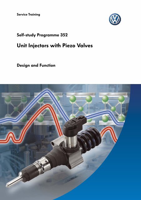
SSP 352 - Unit Injectors with Piezo Valves - Volkspage
SSP 352 - Unit Injectors with Piezo Valves - Volkspage
SSP 352 - Unit Injectors with Piezo Valves - Volkspage
- No tags were found...

You also want an ePaper? Increase the reach of your titles
YUMPU automatically turns print PDFs into web optimized ePapers that Google loves.
IntroductionGeneral InformationThe unit injector <strong>with</strong> piezo valve (version:PPD 1.1) is a further development of the solenoid-typeunit injector. As the name says, the solenoid valve hasbeen replaced by a faster and more controllablepiezovalve. Furthermore the mechanical control of thevarying injection pressures <strong>with</strong>in the unit injector hasbeen improved so that there is no need for aretraction piston. It has therefore been possible toreduce the high-pressure volume in favour ofefficiency.This new type uses the same fitting as the unit injector<strong>with</strong> solenoid valve (PDE-P2) and is also secured <strong>with</strong>2 screws to avoid additional engine assembly costs.In future, the new unit injectors will be used in the new2.0l-125kW 4V TDI engine and later in other4-valve TDI engines.S<strong>352</strong>_005Volkswagen Mechatronic GmbH & Co. KG has beenfounded for production of the unit injector <strong>with</strong> piezovalve in collaboration <strong>with</strong> Siemens VDO AutomotiveAG. The new production site is located in Stollberg inSaxony.200 employees are currently working on theproduction of the new unit injector.4
ImprovementsInjectionquantityPilot injectionMain injectionSecondary injection(if required)Control of the injection phasesAs the new piezo valve switches approximately fourtimes faster than the previous solenoid valve, it is nowpossible to close the switching valve and open itagain for each injection phase. This allows moreprecise control of the injection phases and flexiblecontrol of the injection quantities.TimeS<strong>352</strong>_007InjectionpressurePilot injectionVariableinjection intervalsMain injectionSecondary injection(if required)Minimuminjection pressureMaximuminjection pressureTimeS<strong>352</strong>_008Injection pressureEach injection phase has different requirements interms of injection pressure. For example, the pilotinjection phase requires a lower injection pressureand the main injection phase a very high injectionpressure. The extended injection pressure range (130-2200bar) has allowed a further change in this area.As a result, the emission levels are improved andgreater performance is possible.Noise emissionsThe typical noise emissions occur when TDI enginesare idling above all due to the noise generated by theunit injectors, not due to the combustion. These noisesare caused by rapid, large-scale pressure changes<strong>with</strong>in the unit injector that are transmitted to theengine via the unit injector drive.The mechanical noises transferred by the drive arereduced by the smaller pump plunger diameter. Thepower required to drive the unit injector is thereforealso lower.The pressure changes can now be influenced <strong>with</strong> theaid of the faster and more precise piezo valve toreduce the noise.The piezo valve can be controlled so precisely that thepressure build-up and pressure reduction of theindividual injection phases can be influenced.5
IntroductionEfficiencyIn this case, higher efficiency means lower drivingpower and also lower fuel consumption.The higher degree of efficiency has been achieved bysaving on the high-pressure chambers and theretraction piston.This reduces the high-pressure volume and thereforea pump plunger diameter of just 6.35mm is requiredto generate the required injection quantities.<strong>Unit</strong> injector <strong>with</strong> solenoid valvePump plunger diameterValve needleRetraction pistonHigh-pressure chambers, no longer requiredNozzle needleS<strong>352</strong>_0096
DesignOverviewCam rocker armReturn springPump plungerValve for pump/nozzle(piezo valve)Injection camValve needleHigh-pressure chamberCheck valveConverterSealsNozzle spring innozzle spring chamberFuel return lineClosing plungerFuel supply lineNozzle needleS<strong>352</strong>_010Cylinder head8
<strong>Piezo</strong> ValveThe most important new feature on the new unit injector is the piezo valve that replaces the previously usedsolenoid valve. The piezo valve has higher switching rates and its actuator travel can be controlled via the voltagesupply. It comprises a piezo actuator <strong>with</strong> housing and connector, the converter and valve needle in the pumpbarrel.<strong>Piezo</strong> actuatorInverse piezo-electrical effect(simplified crystal structure of a piezo element)<strong>Piezo</strong> element <strong>with</strong>out voltage UStarting length<strong>Piezo</strong> element <strong>with</strong> voltage US<strong>352</strong>_018<strong>Piezo</strong> (Greek) = pressureA well-known application area for piezo elements issensors. Pressure is applied to a piezo element and ameasurable voltage is generated. This behaviour of acrystal structure is called a piezo-electrical effect.When a piezo actuator is used, this effect is reversed.The inverse piezo-electrical effect is used.That means a voltage is applied to the piezo elementand the crystal structure of the piezo element reactsby changing in length.Starting length +change in lengthS<strong>352</strong>_019Simple crystal structureMetal contact <strong>with</strong> voltage supplyChange in length of a piezo elementVoltage US<strong>352</strong>_020The change in length of a piezo element isproportional to the voltage applied. That means thatthe change in length of a piezo element, or the piezoactuator, can be controlled <strong>with</strong> the voltage.The control voltage of the piezo actuator is between100V and 200V.Path (change in length)9
Nozzle Spring ChamberThe nozzle spring chamber contains the nozzle spring that is responsible for closing the nozzle needle and alsoprevents early opening when an injection phase begins. The requirements for the nozzle spring force (nozzleneedle closing force) are very different, however. For example, the nozzle needle needs to open even <strong>with</strong> a lowfuel pressure for a pilot injection while it can only open at a high fuel pressure during the main injection phase.In addition, the nozzle needle should close very quickly after an injection phase. To meet the requirements fornozzle spring force, the nozzle spring needs to be supported for the main injection and for closing of the nozzleneedle by high fuel pressure in the nozzle spring chamber. This support is provided by the check valve and theclosing plunger.Check valveS<strong>352</strong>_024Valve needleNozzle spring chamberAt the end of each injection phase, the nozzle springchamber is filled <strong>with</strong> high-pressure fuel. The pressureis released via the valve needle back into the fuelsupply line and is then held by the supply throttle.The check valve is opened by the high pressure of thefuel thus opening the path to the nozzle springchamber.Nozzle springSupply throttleClosing plungerS<strong>352</strong>_024Nozzle needleCheck valve (open)Fuel supply lineS<strong>352</strong>_025The fuel pressure is reduced in the fuel supply line.The check valve closes as the fuel pressure falls.The pressure that is built up is thus held in the nozzlespring chamber.Check valve(closed)S<strong>352</strong>_02611
DesignClosing plungerClose nozzle needleNozzle springWhen an injection phase is completed, the nozzle springchamber is filled <strong>with</strong> high-pressure fuel. This high-pressure fuelpushes against the closing plunger helping the nozzle spring toclose the nozzle needle. Closing the nozzle needle fast has apositive effect on the exhaust emissions and means theretraction piston used in the solenoid-type unit injectors is notrequired.Closing plungerClose nozzle needleS<strong>352</strong>_027Injection pressure is reducedOpen nozzle needleThe fuel pressure held back in the nozzle spring chamber aftercompletion of the injection phase has an effect on the nextinjection phase.The high fuel pressure also supports the nozzle spring and thusprevents the nozzle needle opening too early.The injection phase starts <strong>with</strong> a high injection pressure.This high injection pressure is particularly important forcombustion and the development of exhaust emissions in themain injection phase.Nozzle needle openS<strong>352</strong>_028Injection pressure is built upPressure reductionThe pilot injection phase needs a low injection pressure,however. Therefore, after an injection cycle (pilot, main andsecondary injection phases), it is important that the fuel pressurecan be reduced in the nozzle spring chamber. This is achieved<strong>with</strong> a leakage gap on the closing plunger. The fuel pressure isreduced between the injection cycles, the nozzle spring is nolonger supported and the pilot injection phase can begin at alow injection pressure.Leakage gap on closing plungerS<strong>352</strong>_02912
Injection ProcessPilot Injection PhaseFill high-pressure chamberThe injection cam movement and the subsequentupwards movement of the cam rocker arm allow thereturn spring to push the pump plunger upwards.The special shape of the injection cam causes a slowupwards movement.The high-pressure chamber is enlarged.The piezo valve is not actuated and the valve needleis therefore open. The high-pressure chamber is filledvia the fuel supply line.Cam rocker armReturn springInjection camValve for pump/nozzle(piezo valve)Pump plungerValve needleHigh-pressure chamberFuel supply lineS<strong>352</strong>_01113
Pilot injection phase endsThe pilot injection phase ends <strong>with</strong> the piezo valveopening the valve needle. The fuel pressure isreduced in the fuel supply line and the nozzle needleis closed by the nozzle spring.The nozzle spring is supported by the decreasing fuelpressure that is held back by the supply throttle andreaches the nozzle spring chamber via the opencheck valve.The high-pressure fuel pushes the closing plunger andthus speeds up the closing of the nozzle needle.Depending on the engine operating mode, the enginecontrol unit can trigger one or two pilot injectionphases per injection cycle.Valve for pump/nozzle(piezo valve)Valve needleCheck valveNozzle spring chamber <strong>with</strong> nozzle springSupply throttleFuel supply lineClosing plungerNozzle needleS<strong>352</strong>_01315
End of main injection phaseThe main injection phase ends when the valve needleis opened. The high fuel pressure is reduced in thefuel supply line and nozzle spring chamber.The nozzle needle is closed by the nozzle spring andclosing plunger.It is cooled in the same way as the unit injector <strong>with</strong>solenoid valve. The fuel is throttled as it flows throughthe injector into the fuel return line and also allows thefuel that leaked into the pump barrel to flow out.Valve for pump/nozzle(piezo valve)Pump plungerValve needleCooling channelCheck valveNozzle spring chamber <strong>with</strong> nozzle springFuel return lineFuel supply lineClosing plungerNozzle needleS<strong>352</strong>_01517
ServiceDiagnosisMonitoring the unit injector valve(piezo valve)Simos PPD 1A new engine control unit called Simos PPD 1 isbeing introduced together <strong>with</strong> the new unit injector<strong>with</strong> piezo valve.The Simos PPD 1 diagnostics work in a similar way tothe Motronic <strong>with</strong> the solenoid-type unit injector.S<strong>352</strong>_031The actual closing time of the valve needle ismeasured by means of a turn in the voltage curve (BIP= Beginning of Injection Period).This voltage change is created by the valve needlehitting the valve seat and the resulting forcecounteracting the piezo actuator movement.A test pulse is triggered for all 5 injection phasesbetween the injection cycles to close the valve needle<strong>with</strong>out interfering influences (e.g. high fuel pressure).<strong>Piezo</strong> valve voltage curveVoltageBIPTimeS<strong>352</strong>_030Exceeding or falling below the control limitIf the BIP is not <strong>with</strong>in a specific control limit, a fault entry will be written to the fault memory. Depending on the typeof fault found, the unit injector involved will be triggered or switched off. If it is switched off, this will prevent furtherdamage to the unit injector and the engine.20
Removal and installationWiring harness for unit injectors and glow plugsConnector forunit injectorConnector for glow plugMounting bracketS<strong>352</strong>_032When you remove the wiring harness for the unit injectors and glow plugs, the wiring duct may not beseparated from the mounting brackets. Bending back the mounting brackets and removing the wiringduct may break wires.ELSA provides detailed information on the procedure.Size and screw mounting<strong>Piezo</strong> valveThe unit injector <strong>with</strong> solenoid valve (PDE-P2/2 mounting screws) and the unit injector <strong>with</strong> piezo valve arethe same size and have the same thread size for the cylinderhead. However, solenoid-type unit injectors cannot bereplaced <strong>with</strong> piezo-type unit injectors due to the differentconnections and control units.S<strong>352</strong>_004Solenoid valve21
ServiceVersions of piezo-type unit injectorThere are two versions of the piezo-type unit injector, the first model (PPD 1.0) and the model describedin this self-study programme (PPD 1.1). The first version is already being used in the 2.0l, 103kW, 4V TDI engine forthe Passat from model year 2006 and will be gradually replaced by the latest version (PPD 1.1). These two types canonly be distinguished by the parts numbers stamped on them and are not interchangeable. If a combination of thetwo is fitted, the engine will run poorly.Check the outside appearance and the parts numbers of the different unit injectors so you do notmix them up when replacing them.Information on special toolsThe T10163 puller together <strong>with</strong> the T10133 slidehammer is not just used to remove the piezo unitinjector, but also to fit it.T10163 pullerT10133 slide hammerS<strong>352</strong>_033The new T10308 assembly sleeves are used to fit theseals for the unit injector <strong>with</strong> piezo valve.S<strong>352</strong>_034T10308 assembly sleevesELSA provides detailed information on the procedure.22
Test YourselfWhich answers are correct?One, several or all answers could be correct.1. Which statements on the unit injector <strong>with</strong> piezo valve are correct?a) A connection to the engine control unit is not needed as a solenoid valve is not used.The injection pressures are controlled purely mechanically <strong>with</strong> the aid of the closing plunger.b) The piezo valve is so fast that it can be opened and closed for each injection phase (pilot, main,secondary).c) Due to the smaller pump plunger diameter, the unit injector <strong>with</strong> piezo valve has a lower high-pressurevolume and is therefore only suitable for diesel engines <strong>with</strong> a small capacity.d) It has been possible to reduce the noise emissions due to lower drive forces and better configuration of thepressure change inside the unit injector.2. Complete the following statements.a) Inverse piezoelectrical effect means that a piezo element .............................................................. when voltage isapplied.b) To ensure that the main injection phase starts <strong>with</strong> a higher injection pressure than the pilot injection phase,the nozzle spring is supported by the ...................................................................................... .3. When removing or installing the unit injectors <strong>with</strong> piezo valve, make sure that ...a) they are removed together <strong>with</strong> the wiring harness.b) the fitting size and mounting (fastening <strong>with</strong> two screws) are the same as the unit injector <strong>with</strong> solenoidvalve.c) the wiring harness can only be removed as a complete unit (wiring duct and mounting brackets).1. b), d)2. a) enlarged (also: expanded)2. b) Closing plunger/high-pressure fuel3. b), c)Answers23
<strong>352</strong>© VOLKSWAGEN AG, WolfsburgAll rights and rights to make technical alterations reserved.000.2811.66.20 Technical status 03/2005Volkswagen AGService Training VK-21Brieffach 199538436 Wolfsburg❀ This paper was manufactured from pulp that was bleached <strong>with</strong>out the use of chlorine.


