


Create successful ePaper yourself
Turn your PDF publications into a flip-book with our unique Google optimized e-Paper software.
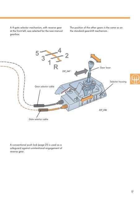
A 4-gate selector mechanism, with reverse gearat the front left, was selected for the new manualgearbox.The position of the other gears is the same as onthe standard gearshift mechanism.531R42237_047Gear leverSelector housingGear selector cable237_046Gate selector cableA conventional push lock (page 21) is used as asafeguard against unintentional engagement ofreverse gear.17
Selector mechanismInner gear change mechanismThe shift movements are transferred to thegearbox from above.The selector shaft is located in the selectormechanism cover.The selector shaft moves axially during selectionmovements and rotates during shift movements.Two spring-loaded balls lock the selector shaft inposition.237_044Selection movementSelector shaftSelector mechanism coverLocking ball(not visible)Selector plateShift movementThe shift forks for 1st/2nd and 3rd/4th gear aremounted in angular continuous ball bearings.These bearings increase the ease of movementof the selector mechanism.The shift fork for 5th gear has low-frictionbearings.When changing gear, the selector plate and theshift fork of the selector shaft are moved by theshift finger.The gear change segments of the shift forks areseated in the sliding sleeve of the relevant gearpair.Shift fork 5th gearShift fork, reverse gearShift fork 1st/2nd gear237_058Shift fork 3rd/4th gearAngular continuous ballbearingGear change segment18
The selection movementThe selection movement (right-left) initiated atthe gear lever is translated to backward andforward movement of the gate selector cable viathe selector lever.The selector lever is mounted in pivot bearingson the bearing shaft.Selection movementGear lever bearingBall guideSelector leverGear leverBearing pinRelay leverGate selector cable237_053SlipperThe backward and forward movements of theselector cable are translated to an up/downmovement of the selector shaft by the outermechanism on the gearbox.For this purpose, the gate selector cable is fixedto the relay lever. The relay lever is mounted inpivot bearings and connected non-rigidly to theselector shaft by means of a slipper.In the gearbox, this up/down movement locatesthe shift finger on the selector shaft in therelevant selector plate which the selected gear isto be engaged in (1st/2nd gear; 3rd/4th gear; 5thgear or reverse gear).237_056Shift finger(concealed)Selector plateSelector shaft19
Selector mechanismThe gearshift movementShift movementThe direct gear shift movement is transferred viathe selector lever guide to the gear selectorcable.If the gear lever is moved forwards or backwardsin the direction of the individual gears, the gearselector cable is pulled or pushed in the oppositedirection to the selector lever movement.Ball guideGear lever bearingGear leverRelay leverSlipperCam on gearshift leverBalanceweightGear selector cableThe forward or reverse movement of the gearselector cable during the gearshift causes theselector shaft to rotate.The movable slipper keeps the gate selectorcable relay lever unchanged in the positionselected.237_054In the gearbox, the shift finger on the selectorshaft moves the selector plate during this rotarymovement. In turn, the selector shaft drives theshift fork and shifts the gear change sleeve.The gear is now engaged.Selector plateShift fingerReverse gear engagedSelector shaft237_05720
The reverse gear lockA push lock serves as a safeguard againstunintentional engagement of reverse gear.2Gear leverThe push lock is integrated in the selectorhousing.The driver has to overcome the push lock firstbefore reverse gear can be selected andengaged.Pressure springSelectorlever guide1Selector housingPressure springSelector lever guide12Press downSelect gear2237_055Gear leverDuring a normal selection stroke of the forwardgears, the locking cam of the gear lever comesup against the lock (an integral part of theselector housing).Interlock237_059Locking cam1When the gear lever is pressed down against thepressure spring, it glides downwards through thespherical selector lever guide; the locking cam isnow located below the interlock.237_06<strong>02</strong>During the reverse gear selection movement thatfollows, the interlock is bypassed allowing thereverse gear to be selected.237_061The pressure spring again pushes up the gearlever in the engaged position and holds it in thereverse position.237_06221
ServiceAdjusting the cable-operatedgearboxAdjustment of the cable-operated gearbox hasbeen simplified by an angle piece on the selectormechanism cover and a locating pin for the gearlever.Gear selectorcableGate selectorcableThe adjustment always begins when the gearboxis in the neutral position:– To detach the selector cables, follow thisprocedure:112Draw the locking mechanism at the gearselector cable and at the gate selector cableforwards as far as the stop. 1 Afterwards,engage locking mechanism by turninganticlockwise. 2 The selector cables can nowbe adjusted for length.2237_048– To arrest the selector shaft, follow thisprocedure:An angle piece which locates the selectorshaft is fixed to the selector mechanism cover.To locate the selector shaft, press down theselector shaft by hand in the gate for 1st/2ndgear. When you press down the selectorshaft, 1 press the angle piece towards theselector shaft 2 and then rotate in directionof arrow. 3 It engages and locates theselector shaft in this position.231237_049Angle pieceSelectormechanism cover22
R 1 3 5Position of gear leverduring the setting operationLocating pinT10<strong>02</strong>72 4237_052Locating hole– To arrest the gear lever, follow thisprocedure:With the engine running at idling speed,locate the gear lever in the gate of the 1st/2nd gear.The gear lever has a locating hole. Insert thelocating pin T10<strong>02</strong>7 through this bore andinto the hole below it in the selector housing.Selector housing237_050– To fix the selector cables in position, followthis procedure:The locking mechanism on the gate selectorcable and on the gear selector cable can nowbe turned clockwise.The spring presses the locking mechanism intothe set position and secures it.Afterwards, detach the angle piece againand pull out the locating pin.The gear lever should now be in the gate ofthe 3rd/4th gear, with the engine running atidling speed.237_05123
SensorsRoad speed displayAn impulse sender wheel milled in thedifferential housing generates the signals thatspeedometer sender G22 requires to determinethe actual road speed of the vehicle.Speedometer sender G22 is inserted in a drillhole in the gearbox housing from the outside.Speedometer senderG22Reference mark ondifferential housing237_013The sender operates according to the Hallsender principle. The electrical impulsesgenerated by the sender are transmited to thecontrol unit in the dash panel insert. Here, thesignals are conditioned for the actual roadspeed and mileage display.Advantage:Ultra-high display accuracy, smooth running,temperature resistant.G22 J285 G21237_015Electrical circuitD +15 Ignition switch, terminal 15G21 SpeedometerG22 Speedometer senderJ285 Control unit in dash panel insertD+15G21J285G2231237_01424
Reversing light switch F4The reversing light switch is screwed into in thegearbox housing at the side.Reversing light switch F4When reverse is engaged, the switch is actuatedby a rise on the reverse gear selector plate.The electrical circuit for the reversing lights isclosed.Gearbox housingRiseReverse gear selectorplate237_018D+15Electrical circuitF4D +15 Ignition switch, terminal 15F4 Reversing light switchM16 Reversing light bulb, leftM17 Reversing light bulb, rightM16M1731237_<strong>02</strong><strong>02</strong>5
6-speed versionGearbox designModifications made for6-speed version237_001In principle, the 6-speed gearbox has the samearchitecture as the 5-speed gearbox.The gearbox housing cover had to be extendedto accomodate the 6th gear, which also involvedextending the input and output shafts.The synchromesh body for the 5th gear wasdesigned so that it can also be used to engage6th gear.26
Modifications to the 5-speed versionThe components for the 6th gear are arranged inthe gearbox housing cover.The gearbox housing coverSleeveNeedle bearingAlso covers the input and output shaft bearings.Compared to the 5-speed version manufacturedfrom sheet steel, a magnesium casting was used.The input and output shaftsRollerbearingChange gear,6th gearWere extended to accomodate the gear wheelsand change gears for the 6th gear.The change gear for the 6th gear runs in needlebearings on a sleeve of the input shaft. Thesleeve is also used as a support bearing by theinput shaft in the gearbox housing cover.The gear wheel for the 6th gear is located on theoutput shaft by means of longitudinal toothingand is mounted, with a collar, in the rollerbearing of the gearbox housing cover.Gearbox housing cover237_0656th gear wheel, withlongitudinal toothingRoller bearing27
36-speed versionForce pathEngine torque is transferred to the gearbox viathe input shaft.In accordance with the gear selected, enginetorque is transferred via the synchromesh bodyfor 5th/6th gear to the output shaft and fromhere to the differential.5237_<strong>02</strong>556R 124237_<strong>02</strong>46237_<strong>02</strong>628
Notes29
Test your knowledgeWhat answers are correct?Sometime only one answer will be correct.However, more than one – or all of the answers may alsobe correct.Please fill in the gaps.1. In the <strong>02</strong>T manual gearbox, the gear and final drive ratios can be varied to a considerabledegree. The advantages are:A. Maximum ratio spread.B. An optimum compromise between sporty and economical driving modes is possible for allvehicle applications.C. It is possible to use the gearbox for different engine capacities and platformsthroughout the Group.2. The gearbox housing is manufactured from magnesium. The advantages are:A. Drastic weight savings.B. Enhanced vibration and noise comfort.C. Considerable savings on cost of materials.3. A characteristic of the gearbox is its modular design. Name at least three gearboxmodules/assemblies.............................................................................................................................................................................................................................................................................................................................................................................................................................................................................................................................................4. The gearbox is equipped with the standard cable-operated transmission. The advantages are:A. Low friction losses during operation.B. The lateral forces and bending moments acting on the elements of the inner and outerselector mechanisms are kept to a minimum.C. Mechanical vibration is isolated from the drive line region.30
5. The angle piece on the selector mechanism cover is used toA. Fix the selector shaft in a pre-defined position.B. Fix the gearshift lever in a pre-defined position.C. Simplify adjustment of the standard cable-operated transmission.6. The range of special tools includes locating pin T10<strong>02</strong>7. It is used toA. Fix the gear lever in the gate for 1st/2nd gear.B. Lock the selector shaft.C. Adjust the gear lever in relation to the selector housing.7. Road speed is reduced viaA. Mechanical intermediate steps … speedometer drive wheel andspeedometer drive shaft.B. Sensors on the gearbox and wireless transmission to the control unit inthe dash panel insert.C. Direct engine speed reduction at the differential housing by a Hall sender andsubsequent transfer to the control unit in the dash panel insert.8. The bearing support is a new feature of the transmission shaft bearing.A. As a result, the bearings can be exchanged quickly, easily and individually.B. After repair work, the bearing support must be replaced completely.C. The complete shaft and gear packet of the input and output shafts andthe bearing support is pre-assembled as a module.Solutions1. A., B.; 2. A.; 3.Clutch release lever, selector shaft with selector mechanism cover, inner gear changemechanism, bearing support for input and output shafts; 4. C.; 5. A., C.; 6. A., C.; 7. C.; 8. B., C.31
Service. 237For internal use only © VOLKSWAGEN AG, WolfsburgAll rights reserved. Technical specifications subject to change without notice.940.2810.56.20 Technical status: 01/00❀ This paper is produced fromnon-chlorine-bleached pulp.


