324 - Audi A6 2005 - VolksPage.Net
324 - Audi A6 2005 - VolksPage.Net
324 - Audi A6 2005 - VolksPage.Net
Create successful ePaper yourself
Turn your PDF publications into a flip-book with our unique Google optimized e-Paper software.
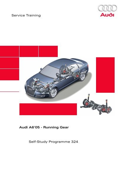
Service Training<strong>Audi</strong> <strong>A6</strong>‘05 - Running GearSelf-Study Programme <strong>324</strong>
General informationThe basic version of the <strong>Audi</strong> <strong>A6</strong>’05 is equipped with a steel spring chassis. There are three different types ofrunning gear:Normal running gear:Sports-style running gear:Rough-terrain running gear:Designation: 1BADesignation: 1BE, vehicle trim is positioned 20 mm lower than on the normalrunning gearDesignation: 1BR, vehicle trim is positioned 13 mm higher than on the normalrunning gear<strong>324</strong>_000
ContentsFront axleOverview . . . . . . . . . . . . . . . . . . . . . . . . . . . . . . . . . . . . . . . . . . . . . . . . . . . . . . . . . . . . . 4System components . . . . . . . . . . . . . . . . . . . . . . . . . . . . . . . . . . . . . . . . . . . . . . . . . . . 5Rear axleOverview . . . . . . . . . . . . . . . . . . . . . . . . . . . . . . . . . . . . . . . . . . . . . . . . . . . . . . . . . . . . 10System components . . . . . . . . . . . . . . . . . . . . . . . . . . . . . . . . . . . . . . . . . . . . . . . . . . 11Running gear alignment/adjustmentAdjusting the front axle . . . . . . . . . . . . . . . . . . . . . . . . . . . . . . . . . . . . . . . . . . . . . . . 15Adjusting the rear axle . . . . . . . . . . . . . . . . . . . . . . . . . . . . . . . . . . . . . . . . . . . . . . . . 16Brake systemWheel brake. . . . . . . . . . . . . . . . . . . . . . . . . . . . . . . . . . . . . . . . . . . . . . . . . . . . . . . . . . 17Electromechanical parking brake – EPB. . . . . . . . . . . . . . . . . . . . . . . . . . . . . . . . . . 20ESP . . . . . . . . . . . . . . . . . . . . . . . . . . . . . . . . . . . . . . . . . . . . . . . . . . . . . . . . . . . . . . . . . 28Steering systemOverview . . . . . . . . . . . . . . . . . . . . . . . . . . . . . . . . . . . . . . . . . . . . . . . . . . . . . . . . . . . . 38System components . . . . . . . . . . . . . . . . . . . . . . . . . . . . . . . . . . . . . . . . . . . . . . . . . . 39Wheels/tyresWheel programme . . . . . . . . . . . . . . . . . . . . . . . . . . . . . . . . . . . . . . . . . . . . . . . . . . . . 46Tyre pressure monitoring . . . . . . . . . . . . . . . . . . . . . . . . . . . . . . . . . . . . . . . . . . . . . . 47Tyre pressure monitoring system for USA . . . . . . . . . . . . . . . . . . . . . . . . . . . . . . . 50The Self-Study Programme provides information on the fundamentals of the design and function of newvehicle models, new vehicle components or new technologies.The Self-Study Programme is not a Workshop Manual!Specified values serve only to make the information easier to understand and relate to the software versionthat was valid at the time the Self-Study Programme (SSP) was created.For maintenance and repair work, please make sure to use the current technical documentation.ReferenceNote
Front axleOverviewThe well-known four-link front axle is also used inthe new <strong>Audi</strong> <strong>A6</strong>’05 (see SSP 161).Given the geometric and kinematic changescompared to the predecessor vehicle, all axlecomponents except for the top-level axle controlarms and the wheel hubs (adopted from the<strong>Audi</strong> A8) are new parts.In addition to improved spring and shock absorbersettings, spring travel has been increased by30 mm. This results in a significant improvement indriving comfort and driving stability. With regard tothe passenger compartment, the axle was movedforward by 83 mm. This provides better axle loaddistribution and has advantages from the point ofview of driving dynamics.Mounting blockGuide armSpring/shockabsorber unitUpper axle control armPivot bracketStabiliserSubframeSupporting armWheel bearing/Wheel hub<strong>324</strong>_0014
System componentsPivot bracketThe pivot bracket is an aluminium forged part,while the support for the trailing arm mount for theguide and supporting joints is formed from pressedzinc/iron-coated bushings. Because of the differentwheel bearing dimensions, there are two types ofpivot brackets.Pivot bracketBushings forcontrol arm supports<strong>324</strong>_002Wheel bearingA 2nd generation wheel bearing (double-flangebearing) is used. Because of the different axle loads,an 85-mm Ø bearing is used for all 4-cylinderengines and for 6-cylinder petrol engines.All other engines (higher axle loads) have abearing Ø of 92 mm. The ring for wheel speedsensing is part of the wheel bearing.Wheel hubThe wheel hub for the 85 mm Ø wheel bearing isthe same part that is used in the <strong>Audi</strong> A8’02.The larger wheel hub (Ø = 92 mm) is adoptedfrom the <strong>Audi</strong> A8’03).Wheel hubWheel bearing<strong>324</strong>_0035
Front axleMounting blockThe mounting block is made of aluminium poralcasting. It is bolted to the body and is used tosupport the top control arms and thespring/shock absorber unit.NoteObserve the tightening sequence for securingthe bolts to the body, see Workshop Manual.<strong>324</strong>_004Control armThe top- and bottom-level control arms arealuminium forged parts. The top-level control armsare the same parts that are used in the <strong>Audi</strong> A8’03.Unlike the predecessor model, however, the bottomcontrol arms are larger because of the highermaximum axle load.NoteThe new product T 40067 is used to secure thetop control arms to the pivot bracket.<strong>324</strong>_0056
Spring/shock absorber unitTwin-tube shock absorbers with linear steel springsare used.The more direct spring strut setting compared tothe predecessor vehicle as well as the increasedspring travel results in a significantly betterresponse.Additional springShock absorbermountingShock absorberBottom spring plate<strong>324</strong>_0067
Front axleSubframeThe subframe is a monocoque-constructed, weldedpart made of high-strength steel. To make it morerigid, the U shape is closed using a transverse barbolted at the back.A modified subframe is used for all vehicles with the09L gearbox. This gearbox is mounted on twoadditional subframe brackets.The rubber-metal mounts, which are larger than inthe predecessor model, ensure improved passengercompartment comfort in all road conditions.Bracket forengine mountTransverse bar<strong>324</strong>_007Subframe8
StabiliserTwo tubular stabilisers are used to reduce theweight. Vehicles with a quattro sports-style runninggear have a stabiliser with a higher spring constant.Bracket forengine mountStabiliser<strong>324</strong>_008Stabiliser barStabiliser<strong>324</strong>_0099
Rear axleOverviewThe rear axle represents a further development ofthe trapezoid link axle, with which you may befamiliar from the A4’00. Because of the geometricand kinematic changes compared with thepredecessor vehicle and the use of the trapezoidlink axle, all axle components are new parts.The axle struts are now longer compared with theA4’00 in order to guarantee a larger toe width.For vehicles with V8 TDI engines with quattro dirve,the toe width on the rear axle is reduced so thatwider tyres can be used. This is achieved usingmodified wheel hubs.Wheel carrierSubframeTransverse control armShock absorberSpringTrapezoidal control armWheel bearing<strong>324</strong>_01010
System componentsWheel carrierThe wheel carrier is made of cast aluminium.It is manufactured using the Cobapress method.A subsequent forging procedure is then performedwhile it is still hot. This achieves a veryhomogeneous material structure with highcomponent strength.Wheel carrierWheel bearing /wheel hubWheel bearings and wheel hubsFront wheel drive:3rd generation wheel bearings are used. The wheelbearing and wheel hub thus form one structuralunit.<strong>324</strong>_011quattro:The same wheel bearings, which are installed onthe front axle of the <strong>Audi</strong> A8’03, are used here(2nd generation, diameter = 92 mm).Wheel carrierWheel bearingWheel hub<strong>324</strong>_01211
Rear axleTrapezoidal control armThe trapezoid control arm is made of high-strengthsteel. It is the connecting element between thewheel carrier and the subframe on the bottom level.The control arm also has a plastic cover to protect itagainst stone/chipping damage.<strong>324</strong>_013Transverse control armThe top control arm is a steel welded part. The sameparts are now used on the right and left axle side.<strong>324</strong>_014Toe control armThe toe control arm is a steel part. An additionalplastic cover is fitted as chipping protection on therough-terrain running gear.<strong>324</strong>_01512
SpringThe spring has a linear characteristic. For the roughterrainrunning gear, additional washers are fittedbetween the springs and the body in order to raisethe position of the trim when the vehicle is empty(+13 mm compared with the normal running gear).Washer forrough-terrainrunning gearTop spring plateNoteDue to the installation position of the spring,the new special tool VAS 6274 is used to tensionthe spring.Please observe correct installation position forspring.See current Workshop Manual.Bottom spring plate<strong>324</strong>_016Shock absorberA conventional twin-tube shock absorber is used.Shock absorber mountingAdditional springShock absorber<strong>324</strong>_01713
Rear axleSubframeThe subframe is a welded construction made ofinternal high-pressure recast (IHU) parts.The quattro subframe is fundamentally different tothe front-wheel-drive variant in that it has a frontcross tube, which is used for mounting the rear axletransmission.Four hydraulic mounts are used for mounting on thebody. The mounts are not the same – the front andrear mounts have different spring properties (springstiffness). The same mounts are used for frontwheel-driveand quattro vehicles.Front cross tube(for quattro only)Hydraulic mounts<strong>324</strong>_018NoteThe installation position of the mounts inthe subframe is predefined, see currentWorkshop Manual.StabiliserThe stabiliser is mounted on the subframe in rubbermounts and is secured to the trapezoid controlarms with rubber-cushioned connecting rods.Two different stabilisers are used. The stabiliser forthe sports vehicle has a higher torsion resistance.SubframeStabiliserStabiliser<strong>324</strong>_021Connecting rod<strong>324</strong>_02014
Running gear alignment/adjustmentAdjusting the front axleThe basic procedure for aligning and adjusting thefront axle is still the same.Individual toe values and the toe change patternduring spring tensioning/release (= ”toe-in curve”)can be adjusted as before on the four-link front axle.The procedure for this remains unchanged.The camber values can be centred between theright and left axle side. This is done by shifting thesubframe together with the engine mountingbracket sideways.(see current Workshop Manual)Toe adjustmentToe constantadjustmentCamber adjustment<strong>324</strong>_02215
Running gear alignment/adjustmentAdjusting the rear axleThe camber adjustment is performed with aneccentric screw at the position at which the controlarm is bolted to the wheel carrier.Toe adjustment is performed at the front boltsecuring the trapezium control arm to thesubframe.(For further details, see current Workshop Manual)Eccentric screw forcamber adjustmentEccentric screw fortoe adjustment<strong>324</strong>_02316
Brake systemWheel brakeFront-axle overviewEngine 3.0 litre V6 TDI 3.2 litre V6 FSI 4.2 litre V8 MPIMinimum wheel size 16” 16” 17”Brake type FNR-G 60 16” FNR-G 60 16” FNR-G 60 17”Number of pistons 1 1 1Piston diameter (mm) 60 60 60Brake disc diameter (mm) xthickness (mm)321 x 30Ventilated321 x 30Ventilated347 x 30Ventilated<strong>324</strong>_024a17
Brake systemWheel brakeRear-axle overviewEngine 3.0 litre V6 TDI 3.2 litre V6 FSI 4.2 litre V8 MPIMinimum wheel size 16” 16” 17”Brake type Colette II C41 Colette II C41 Colette II C43Number of pistons 1 1 1Piston diameter (mm) 41 41 43Brake disc diameter (mm) xthickness (mm)302 x 12Not ventilated302 x 12Not ventilated330 x 22Ventilated<strong>324</strong>_025c18
System componentsBrake master cylinderAn 8/9-inch tandem brake master cylinder is used.The piston diameter has been increased. The brakemaster cylinder is the same design as S4 and RS6.By optimising the internal design, it was possible toimprove brake pressure metering and the reportingof the current braking pressure to the driver.<strong>324</strong>_025aBrake servo unitThe brake servo unit operates according to the dualrateprinciple.(For a description of how it works, see SSP 313.)The vacuum is supplied by the intake pipe vacuum.The well-known electric vacuum pump UP-28is used for the V8 engine with automatictransmission to improve the vacuum supply duringengine warm-up. A mechanical vacuum pump isused for the V6 and diesel engines.Brake fluid reservoirThe brake fluid reservoir was adopted from the A4.Additionalpower assistanceDual-rate characteristicStandard characteristicBrake pressurePedal pressure<strong>324</strong>_025b19
Brake systemElectromechanical parking brake - EPBGeneral informationFollowing its initial introduction in the <strong>Audi</strong> A8, theelectrical parking brake EPB is now also used in the<strong>Audi</strong> <strong>A6</strong>’05. The basic mechanical design, the boostfactor levels and the general functionality are stillthe same (see SSP 285). The adaptation of the EPBto suit the <strong>A6</strong>’05 has resulted in the new featuresdescribed below.<strong>324</strong>_025cRight locking motor V283Left locking motor V282Control unit for electromechanicalparking brake J540 in luggagecompartment, rightControl unit with display unit in dashboard insert J285Pressure switch for parking brake F234<strong>324</strong>_025d20
System componentsParking brake motor V282/V283The engine and gearbox are now mountedseparately in two damping elements and thusseparated from the housing. The engine andgearbox are positioned exactly in the dampingelements using a positioning plate.The toothed belt for the gearbox drive is nowhelical-cut at a 2° angle. These measuressignificantly improve the noise characteristic whenthe engine and gear mechanism are running.Damping element on transmission mountHelical-cut toothed beltPositioning plateDamping element on engine mount<strong>324</strong>_02721
System componentsEPB fault displaysThe EPB fault displays in the dashboard insert andthe audible signal (gong) are now activated by theCAN Instrument Cluster. Without the discreteactivation function, the driver in the control unitwith display unit in the dashboard insert J285 is nolonger needed.The operating and display concept corresponds tothat used in the <strong>Audi</strong> A8 (see SSP 285).<strong>324</strong>_02923
Brake systemFunctionalitiesDriveAssistThe DriveAssist function can now be used on allvehicles with manual gearbox. The brake openingtime depends on the vehicle tilt, accelerator pedalposition, clutch pedal position and clutching speed.The EPB control unit calculates the clutching speedby evaluating the change in the position of theclutch pedal over time. A newly developed contactfreepedal sensor is used to record the clutch pedalposition.The EPB control unit must also consider whetherthe vehicle, which is positioned on a slope, is takingoff forwards or backwards.By evaluating a CAN message from the control unitfor central convenience electronics J393, theEPB control unit determines whether thereversing light is on.While detecting the intended forward or reversetravel down a slope, the brake is opened for drivingoff, even with a considerably reduced enginetorque.Generally, the function can only be activated whenthe safety belt is fastened.The DriveAssist function can no longer bedeactivated in Customer Service.24
V282Left parking brake motorV282Right parking brake motorAcceleratorpedal valueEngine torqueEngine speedTilt angle sensor(integrated in control unit)J540Control unit for electromechanicalParking brakeBelt bucklestatusJ234Airbag control unitJ533Diagnostic interfaceJ220Motronic control unitClutch pedal valueJ519On-board power supply control unitReversing light switchAcceleratorpedal valueCAN DriveCAN Convenience<strong>324</strong>_03025
Brake systemFunction diagramDimmingsignal<strong>324</strong>_031F234Pressure switch for parking brakeInput signalF36Clutch pedal switchOutput signalJ540Control unit for electromechanical parking brakePositiveJ285Control unit with display unit in dashboard insertGroundV282Left parking brake motorCAN DriveV283Right parking brake motor26
CAN Data ExchangeJ540 Control unit for electric parking brakeParking brake status – open/closed (2)Clamping force reached (2)Deceleration request (2)Deceleration request approval (2)Terminal 15 status (2)Parking brake fault status regarding cl. force reached (2)Tilt angle (2)Indicator light for EPB function (6)Brake indicator light (6)EPB malfunction indicator light (6)Sleep indication (1)Warning tone/text messages (6)Fault memory entry (1)J393 Central control unit for conveniencesystem (7)Reversing light on/offJ518 Control unit for access and startauthorisation (5)Steering wheel lock statusTerminal 15 onJ533 Data bus diagnosis interface (1)Mileage, oldTime, oldSleep acknowledgeJ104 Brake control unit (2)Wheel speedsASR/MSR requestABS braking operationESP/EPB operationBrake pressureEPB deceleration availableEPB message plausibleSystem statusJ220 Motronic control unit (3)Engine speedEmpty gas informationAccelerator pedal valueEngine torque lossJ285 Control unit in dashboard insert (6)MileageDateTimeIdle timeOutside temperatureJ217 Control unit for automatic transmission(4)Transmission Info (stepped operation or CVT)Target gear/engaged gearSelector lever positionConverter clutch statusJ234 Airbag control unitBelt buckle query, driver’sInformation sent by control unit J540CAN Instrument ClusterInformation received and evaluated bycontrol unit J540CAN DiagnosisCAN Drive<strong>324</strong>_032CAN Convenience27
Brake systemESPGeneral informationA new ESP generation from Bosch in the formof ESP 8.0 is used in the <strong>Audi</strong> <strong>A6</strong>’05.The familiar basic functions already available in theother <strong>Audi</strong> models have been adapted to theconditions in the <strong>A6</strong>’05.The basic functionalities of the subfunctions EBD,ABS, TCS, EDTC, EDL, ESP and ECD are the same asin the predecessor version 5.7.The control unit and hydraulic unit cannot beseparated in Customer Service. There are twodifferent parts for front-wheel-drive and quattrodrive.Design and functionChanges compared with ESP 5.7– The hydraulic unit and control unit are nowlighter (1.6 kg) and smaller as a result of furtherminiaturisation of the electronics. At the sametime, the hydraulic efficiency has been improvedsignificantly.The computing power has been increasedsignificantly through the use of a new microcontrollerfamily and a more efficient processor.The control unit can now be flashed.<strong>324</strong>_03428
– The ESP pressure sensor is integrated into thehydraulic unit. This integration offers particularadvantages with regard to reducing the amountof cables required and increasing functionalsafety.The sensor measures the brake pressure at theinput of the hydraulic control unit in the primarycircuit.Pump motorPilot valvesValve blockPressuresensorControl unit<strong>324</strong>_035– The sensor unit G-419 still contains the sensorsG200 – Transverse acceleration sensor – andG202 – Rotation rate sensor. It is installed on thetunnel in the centre console. The sensor unit nowcommunicates with the control unit through thePrivate CAN.The Private CAN is a high-speed CAN, whichsupports real time. In spite of nominally similardata transfer rates to those on the CAN Drive, thePrivate CAN assures very fast data transmissionbetween the sensor unit and the ESP control unitat a virtually constant speed.<strong>324</strong>_03629
Brake system– While travelling in rain or snow, the front brakepads are applied periodically (every 185 seconds)to the brake discs at a minimum pressure (0.5 -1.5 bar) for a short time (approx. 2.5 seconds).This cleans the brake pads and discs, therebyimproving braking response. To do this, thewindscreen wiper must be switched on and thevehicle speed must be > 70 km/h.– The opening cross-section of the ESP switch-overvalves can now be varied by changing theactivating signal as required. (For details of howthis works, see SSP285, page 49.)As a result, the brake pressure can be regulatedmore specifically, the acoustics are improved andpulsations on the brake pedal are significantlyreduced.– The so-called ”hill holder” function is used forvehicles with Multitronic transmission. If thedriver takes his/her foot off the brake pedal afterstopping on a slope, the momentary brakingpressure is kept constant by closing the ABSoutlet valves. If the driver puts his/her foot on tothe accelerator pedal within a time period ofmax. one second, the brake is then opened if theavailable engine torque is sufficient to preventthe vehicle from rolling back.If the accelerator pedal is not pressedimmediately after letting off the brake pedal, thebrake is opened again after one second. Thisfunction helps the driver to take off again afterstopping for a short time on a slope.Unlike ”traditional” automatic gearboxes,Multitronic gearboxes do not have a creepfunction for when the vehicle is stationary andin gear.30
– The functionality of the button E256 for ESP andASR has been enhanced as follows:Pressing the button quickly (
Brake systemFunction diagramDimmingsignal32
J104J393G419G200G202Control unit for ABS with EDL/TCS/ESPCentral contr. unit for convenience systemESP sensor unitTransverse acceleration sensorRotation rate sensorE256 TCS/ESP buttonF63 Brake pedal switchS FuseG44-47 Engine speed sensorV64N99/101/133/134N100/102/135/136N225N226N227N228abcdegABS hydraulic pumpABS inlet valvesABS outlet valvesPilot valve -1- for driving dynamics contr.Pilot valve -2- for driving dynamics contr.High-pressure switch-over valve -1- fordriving dynamics controlHigh-pressure switch-over valve -2- fordriving dynamics controlBrake light switch signalBrake test switch signalPlug coupling for retrofitting, wheelspeed gauge signalSignal from rear right speed sensorSignal from rear left speed sensorMotronic power supply relayCANDriveInput signalOutput signalPositiveGroundCAN Drive<strong>324</strong>_03933
Brake systemCAN Data ExchangeJ104 Brake control unitASR/MSR request/torque specifications (1,2,3,6,8)ABS braking (1,2,3,6,7,8)EBV/EDS operation (1,2,3,6)ESP operation (1,2,3,6,7,8)ASR shift influence (3,6)ABS/ESP/brake indicator light (1,10)Brake light switch signal (2,7,9)Brake test switch signal (2)Driving speed (1,2,3)ESP system status (1,6,8)Passive ESP activated (6)Transverse acceleration request (4)Transverse acceleration (3,7)Wheel speeds (1,2,3,8,9)Direction of travel of wheels (9)Average wheel speed (1,10)Yaw speed request (4)Yaw speed (1,9)Brake pressure in brake master cylinder (7,8,9)Diagnosis transport duct opening (1,6)Fault memory entry (1,12)Calibration message (5)Brake light for ECD braking (1,11)EPB deceleration available (8)Vehicle speed (2,7)Initialisation and calibration of steering-angle sensor (5)Rough-terrain trim (1,2,6)ABS in diagnosis (6)Brake temperature (8)Brake status – acc request (13)Deceleration active through electric parking brake (8)G419 Sensor unitTransverse accelerationrotation rateJ533 Data bus diagnosis interface (1)Diagnosis mode openingDateTimeMileageSleep acknowledgeFront wiper onReversing light switch (actuated/not actuated)Reversing light (on/off)Data link connector (12)J428 Control unit for distance control (13)Deceleration requestBrake pressure dynamics (reduction/build-up)Brake system pre-fillingForced ESP activationJ393 Central control unit for convenience system (11)J285 Control unit with display unitin dashboard insert (10)Wheel sizeIdle timeOutside temperature34
J220 Motronic control unit (2)Engine data (intake system, displacement, engine power)Engine speedEngine torques (inner torque, mechanical torque loss)Driver setpoint torqueAccelerator pedal valueEmpty gas informationClutch switchGearbox coding informationMaximum transferable torqueMinimum torque for ignition timing retardationNormal operating statusCruise control statusInformation sent bythe power steeringcontrol unitInformation received andevaluated by the powersteering control unitCAN ConvenienceCAN Distance ControlJ217 Control unit for automatic transmission (3)Gearshift activeTarget gear/engaged gearSelector lever position (for CVT gearboxes only)Transmission torque lossCAN Instrument ClusterCAN DiagnosisCAN DriveJ217 Control unit for automatic transmission (3)Gearshift activeTarget gear/engaged gearSelector lever position (for CVT gearboxes only)Transmission torque lossJ527 Steering column switch module (5)G85 Steering-angle sensorSteering wheel angleSteering wheel angle signSteering angle ID (for calibration)Battery detection (terminal 30) offG85 statusJ234 Airbag control unit (6)Brake variantDrive variantBelt buckle query, driver’sPrivate CANA new feature here is theincorporation of theairbag control unit J234in data exchange.Information about thedrive and brake variantsinstalled on the vehicleis stored in the airbagcontrol unit and is readin by the ESP controlunit J104. TheESP control unit J104compares thisinformation with its owncoding. If theinformation does notcorrespond,ESP operation is notpermitted and an entryis recorded in the faultmemory.J197 Level control unit (7)*ESP influenceJ540 Control unit for electric parking brake (8)Status (open/closed)Clamping force reachedDeceleration requestTilt angleJ431Control unit for headlight beam adjustment (9)Receiver onlyThe number shown inbrackets after themessage contentsindicates the control unitresponsible forprocessing thecorrespondinginformation: e.g. ”ASR/MSR request” isprocessed by controlunits no. 2 and 3(J220 and J217).* Not used at start of production (SOP)<strong>324</strong>_04035
Brake systemServiceSignificant changes compared with ESP 5.7The following service topics have been changedsignificantly compared with ESP 5.7:– Calibration of the steering-angle sensor G85is no longer tied in with coding the ESP controlunit J104.– The login code is no longer entered for codingthe ESP control unit J104 in on-board diagnosis.Before coding the ESP control unit, the drive andbrake variants must be coded in the airbagcontrol unit.– Measured-value blocks with extended scope.ReferenceFor a detailed description of the rangeof services available, see currentWorkshop Manual.36
Notes37
Steering systemOverviewA conventional, hydraulic rack-and-pinion servosteering system is used.A high degree of sporty steering precision has beenachieved through the consistent furtherdevelopment of the steering used in thepredecessor model. The speed-dependentServotronic servo-support is available as standard.Servotronic II, which was used before in the <strong>Audi</strong>A8, is also used here. (For details of design andfunction, see SSP 285.)A mechanically adjustable steering column is usedin the basic model. Electrical adjustment isoptional.Steering gearSteering pumpSuction hoseOil reservoirExpansion hoseReturn lineServo oil coolerReturn hose<strong>324</strong>_04138
System componentsSteering pumpThe vane-type pumps FP4 and FP6, which you mayalready know, are used here.<strong>324</strong>_057Engine Pump type Maximum pumppressure (bar)Feed volumes(cm 3 /rev)Direction of rotation3.0 litre V6 TDI FP4 123 11 Right3.2 litre V6 FSIFP6 FP4 120 12,5 Right4.2 litre V8 MPI FP6 chain drive 123 13 LeftSystem componentsSteering gearFour different types of steering gear are used.There are geometric differences between right- andleft-hand drive vehicles.In addition, steering gears with more directtransmission ratios and bigger track rod joints areused for the powerful eight-cylinder engines.The piston diameter of the steering gear is 44 mm.The rotary valve is bolted to the aluminium-caststeering gear housing as a separate component.The steering gear is connected to the bottom of theradiator tank with three bolts.Generally, a constant conversion of steering wheelmovement into track rod stroke movement isachieved.NoteIf repairs are needed, the entire steeringgear/rotary valve unit must be replaced(see current Workshop Manual).39
Steering systemSteering gearSolenoid valve forServotronicRotary valveBolting points<strong>324</strong>_044System componentsServotronicSolenoid valve forServotronicThe control unit -2- for on-board power supply J520activates the solenoid valve for Servotronic. Theinput signal for the control unit is the speed signalfrom the ESP control unit J104.<strong>324</strong>_04540
The functionality of the solenoid valve forServotronic is also used in the <strong>A6</strong>’05 for the firsttime to reduce the thermal load on the steeringpump.The highest thermal load on the pump occurs whenthe steering is held at the limit position. The endposition of the piston in the steering gear is thenreached, but the pump continues to supply oil.This increases the pressure until the pressurecontrolvalve in the pump opens. The pump thenfeeds via short circuit. This means that the suppliedoil travels back to the intake side of the pump theshort way via the pressure-control valve. Thisincreases the oil temperature significantly in a shortspace of time.Pressure-control valve opensPiston in end position<strong>324</strong>_04641
Steering systemIn this situation, the control unit supplies morepower to the solenoid valve. The opening crosssectionof the valve becomes larger than the actualdriven speed requires. As a result, an additional oilstream flows to the tank via the open valve. On itsway, the oil gives off temperature to theenvironment.This reduces the oil temperature. The control unitdetermines the time and amperage for activatingthe solenoid valve based on the steering-angleCAN message from the steering-angle sensor G85.Control is only active at speeds of up to 10 km/h.Valve opensSolenoid valve<strong>324</strong>_047Additional oil stream through the open solenoid valve for Servotronic42
System componentsOil reservoirThe oil reservoir is equipped with a fine filter. Dirtand wear particles are thus effectively kept out ofthe hydraulic system. This keeps wear-and-tear to aminimum, especially on the pump, steering valveand piston seals.Fine filter<strong>324</strong>_047aSystem componentsMechanically adjustable steering columnThe steering column can be adjusted smoothly inboth length and height.The adjustment range is 50 mm length-wise and40 mm height-wise.The steering column is locked by multi-platepackets. When the steering column is locked, theplates are tensioned together by an eccentric screw.(For details of how this works, see SSP 285.)The actuating lever for adjustment is locatedoutside of the critical area for knee impact in theevent of a front crash. The opening kinematics wereadapted in order to implement this position. Thelock is now opened by pulling the lever towards thedriver.Adjustinglever closedAdjustinglever open<strong>324</strong>_047b43
Steering systemRelease tabSteering wiringGuide boxBracketMulti-plate packets foradjustment/clampingAdjusting leverTelescopic shaftDrive for electricsteering lockClamping teeth forsteering pinion gears<strong>324</strong>_047cElectrically adjustable steering columnThe basic design is the same as the mechanicallyadjustable steering column.The same adjusting elements and drive motorsthat are used in the A8’03 are used here. (For detailsof design and function, see SSP 285.)<strong>324</strong>_047d44
Electric steering lockLike the A8’03, the <strong>A6</strong>’05 also has an anelectric steering lock.It is required for the keyless driver access system,which is available as an optional extra.The mechanical design and function are the sameas the locking unit used in the A8’03 (see SSP 285).The electric drive for the lock has been modified.The control unit for the lock drive now alsoperforms all the functions for vehicle access andstart authorisation. (For details, see SSP 326.) Theentire structural unit, comprising drive, locking unitand control unit, cannot be separated from thesteering column.Steering wheelA newly developed three/four-spoke steering-wheelgeneration is used.The technical design of the steering wheel, airbagand operating concept of the multi-functionsteering wheel corresponds to that of the A8’03.<strong>324</strong>_047e<strong>324</strong>_047f45
Wheels/tyresWheel programmeEngineBasic wheels Winter wheels Optional wheels Run flat system PAX4 and 6-cylinder7J x 16 ET 35 (1)Cast alum. wheel205/60 R167J x 16 ET 42 (4)Forged alum. wheel205/60 R16 or225/55 R167.5J x 16 ET 45 (7)Cast alum. wheel225/55 R168J x 17 ET 48 (10)Cast alum. wheel245/45 R17225 x 460 ET 46 (13)Cast alum. wheel(PAX)235/660 - R4607.5J x 16 ET 45 (2)Forged alum. wheel225/55 R16225 x 460 ET 46 (5)Cast alum. wh. (PAX)225/650 - 4607.5J x 17 ET 45 (8)Cast alum. wheel225/50 R178J x 18 ET 48 (11)Cast alum. wheel245/40 R188-cylinder7.5J x 17 ET 45 (3)Cast alum. wheel225/50 R177J x 17 ET 42 (6)Cast alum. wheel225/50 R17 98 M+S7.5J x 17 ET 45 (9)Cast alum. wheel225/50 R178J x 18 ET 48 (12)Forged alum. wheel245/40 R18<strong>324</strong>_048As in the A8’03, the PAX emergency-run system inconjunction with summer and winter tyres is nowalso available as an optional extra for the <strong>A6</strong>’05. The<strong>A6</strong>’05 is thus the first vehicle in its class with thisinnovative system.The PAX system always comes hand-in-hand withthe tyre pressure monitoring system in the <strong>A6</strong>’05.(For details of design and function, see SSP 285.)46
Tyre pressure monitoringGeneral informationA new generation of the tyre pressure monitoringsystem is available for the <strong>Audi</strong> <strong>A6</strong>’05.It is modular in design and is significantly differentfrom the systems used up to now at <strong>Audi</strong> from thepoint of view of functionality and design.A modified system, adapted according to thenational legislation in force in the USA, is usedexclusively for the US market.<strong>324</strong>_058Tyre pressure monitoring system (designed for all markets except USA)DesignThe control unit for tyre pressure monitoring J502 isconnected to CAN Convenience. A transmitter fortyre pressure monitoring G431….G434 is installed ineach wheel housing.The antenna for rear tyre pressure monitoring R96is located between the interior light and the slidingroof module in the roof area.The transmitters and the antenna are linked to thecontrol unit via LIN bus. A tyre-pressure sensorG222….G226 is installed in each wheel.As before, there are two country variants for thesensors and the antenna (433 and 315 MHz).47
Wheels/tyresCommunication: transmitter – sensorCommunication: sensor – antennaControl unit for tyrepressure monitoringJ502Tyre-pressure sensorsG222 - G226Antenna for tyrepressure monitoringR96Transmitters for tyrepressure monitoringG431 - G434<strong>324</strong>_049How it worksThe system’s initialisation phase begins on openingthe driver's door or when terminal 15 is on. Thecontrol unit then sends a special LIN address atoffset times to each transmitter for tyre pressuremonitoring G431...G434 and to the antenna R96.Following initialisation, each transmitter in turnreceives a message from the control unit. Thecurrently addressed transmitter then sends a onceoffradio signal at a frequency of 125 kHz. Given thelimited range of this radio signal, it is only receivedby the related tyre-pressure sensor. The signalprompts the sensor to send the current measuredvalues for pressure and temperature. This signal isrecorded by the antenna and transmitted to thecontrol unit via LIN bus.Following this, no further communication takesplace as long as the vehicle is stationary. The tyrepressuresensors are fitted with centrifugal sensorsfor the detection of rotary movement for thispurpose.The possibility of immediately displaying a warningas soon as terminal 15 comes on and the increasedservice life of the transmitters are distinctadvantages compared to earlier systems. At thestart of a journey, the sensors are allocated to wheelpositions in approx. 2 minutes. Once a drivingspeed of around 20 km/h is reached, each sensorautomatically sends its current measured valueswithout having to wait for a signal from the relatedtransmitter. The radio signal that is sent alsocontains the ID of the relevant sensor. This allowsthe control unit to differentiate between theindividual sensors and their positions in the vehicle.In normal operation, each transmitter sends asignal periodically approx. every 30 seconds.If the sensor measures a fast change in pressure(>0.2 bar/min), it automatically switches to fast-sendmode and sends the current measured values onceper second.48
Operation and displaysThe system is operated in the MMI (see operatinginstructions).The relevant tyre pressures must always be releasedas nominal values when the air-pressure levels inthe tyres/wheels fitted on the vehicle have beenchanged.If wheel positions on the vehicle are interchanged,or if wheels are changed, the position-basednominal pressure values must be re-learned.The MMI includes a new menu item for thispurpose. As is already the case in the A8’03, thepressure and temperature values are only displayedin the MMI.The driver can no longer deactivate the tyrepressure monitoring system.<strong>324</strong>_050As before, we differentiate between a ”hardwarning” (red display) for a large loss of pressure(0.5 bar or more below the nominal pressure whenthe cold-fill pressure is adjusted in accordance withthe specification in the filler flap as nominalpressure levels) and a ”soft warning” (yellowdisplay) for a lower loss of pressure (0.3 bar or morebelow the nominal pressure). If the difference fromthe nominal value is at least 0.3 bar, the control unit”observes” the difference for a while withoutimmediately issuing a warning.If the difference of at least 0.3 bar remainsunchanged, a ”soft warning” is issued after17 minutes.<strong>324</strong>_051If the control unit detects a difference from thenominal pressure of at least 0.5 bar for two directlyconsecutive measured values, a ”hard warning” isissued.In addition to the optical display, an audiblewarning is also issued in the form of gongs.<strong>324</strong>_05249
Wheels/tyresTyre pressure monitoring system for USADesignThe transmitters for tyre pressure monitoring G431 -G434 are not used. The tyre-pressure sensorsG222....G225 and the antenna R96 are the sameparts that are used in the system for all othermarkets. The control unit for tyre pressuremonitoring J502 has a different software partnumber due to the modified software.How it worksThis system essentially works in the same way asthe known systems that are already in use: The tyrepressuresensors G222....G225 send regular radiosignals containing their individual IDs and thecurrent tyre pressure levels and tyre temperatures.These signals are then received by the sharedantenna R96 and transmitted to the control unitvia the LIN bus.No position detection is performed. The control unitmerely assigns the sensors to the vehicle. A drivingtime of up to 20 minutes is required for thisfollowing ”wheel change” confirmation in the MMI.The vehicle speed must be more than 40 km/h. Thecurrent measured values are compared with thenominal values released by the driver. If definedlimit values are exceeded, a warning is issued to thedriver.50
Operation and displayThe current tyre pressure levels are released asnominal values in the MMI. Warnings are indicatedby the legally required yellow indicator light for tyrepressure monitoring in the dashboard insert.In the US, a warning is issued in the event of a lossin pressure of more than 75 % of the pressureplacard (nominal pressure in the filler flap:= coded value) or if the loss in pressure is more than0.4 bar at vehicle speeds of more than 160 km/h or ifthe loss in pressure is greater than 0.5 bar,depending on which condition applies.<strong>324</strong>_05451
Wheels/tyresFunction diagram<strong>324</strong>_055J502Control unit for tyre pressure monitoringLIN busR96Antenna for tyre pressure monitoring, rearCAN ConvenienceG222 - G225Tyre-pressure sensorsPositiveGround52
CAN Data ExchangeJ502 Control unit for tyre pressuremonitoringIdentifier allocation (1,2)Request to transmitters (2)Warning signs of system faults (5)Pressure, temperature (8)R96 Antenna for tyre pressure monitoring(1)Tyre pressure levels, temperatures,sensor battery statusLevel of received signalsG431 - G434 Transmitter for tyre pressuremonitoring (2)*Receiver onlyJ518 Control unit for access and startauthorisation (3)Terminal 15 statusJ533 Data bus diagnosis interface (1)MileageDateTimeJ386 Driver’s door control unit (4)”Door open” signalJ220 Motronic control unit (7)Engine speedJ523 Control unit for display andoperating unit for front information (8)User requests (save pressure levels,change wheels, pressure/temperaturedisplays)J285 Control unit with display unit indashboard insert (5)Outside temperatureJ104 ESP control unit (6)Speed signal<strong>324</strong>_056Information sent by control unit J502* not for USA versionInformation received and evaluated bycontrol unit J502CAN DriveCAN ConvenienceCAN Instrument ClusterMOST busLIN bus53
54Notes
Notes55
Vorsprung durch Technik www.audi.co.uk<strong>324</strong>All rights reserved.Subject totechnical change.CopyrightAUDI AGI/VK-35Service.training@audi.deFax +49-841/89-36367AUDI AGD-85045 IngolstadtTechnical release 01/04Printed in GermanyA04.5S00.07.20


