Batteriestecker - Atech Antriebstechnik
Batteriestecker - Atech Antriebstechnik
Batteriestecker - Atech Antriebstechnik

Create successful ePaper yourself
Turn your PDF publications into a flip-book with our unique Google optimized e-Paper software.
Performed with Emotion<br />
Built by Intelligence<br />
<strong>Batteriestecker</strong>
Legal Info & Global Presence<br />
APP ® Global Distribution Network Includes the Following Countries Along With Many Others:<br />
Argentina, Australia, Belgium, Brazil, Canada, Chile, China, Columbia, Denmark, France, Germany, Greece, Hong Kong, Ireland,<br />
Israel, Italy, Japan, Mexico, New Zealand, Norway, Peru, Poland, Portugal, Singapore, Slovenia, South Africa, South Korea, Spain,<br />
Switzerland, Thailand, Turkey, United Kingdom and United States.<br />
APP ® ’s philosophy is to provide products and services within the trading markets of our customers. We currently serve<br />
our worldwide customer base from customer support and manufacturing facilities in Sterling, MA, U.S.A., Warrington<br />
UK for European customers, as well as three Asia Pacific facilities: Shenzhen, China, Shatin Hong Kong and Taichung<br />
City 407, Taiwan (R.O.C.).<br />
Today, as a result of innovative design and development, APP ® has evolved into a valued supplier for a wide variety of<br />
markets including Back-up Power, Telecom / Datacom, Alternative Energy Generation & Distribution, Medical Equipment,<br />
Defense, and the Material Handling Industries.<br />
APP ® has established a reputation for high quality products, on-time deliveries, and excellent customer service. As a<br />
result of modern manufacturing techniques and rigorous quality control measures, APP ® assures customers receive<br />
the quality products they deserve.<br />
As a global company dedicated to best environmental practice, APP ® has taken steps to meet the RoHS directive for<br />
virtually all products. The RoHS status for individual APP ® products is readily accessible to customers twenty-four hours<br />
a day, seven days a week online. APP ® looks forward to the challenges posed by the new technologies of the future and<br />
will continue its century long tradition of design excellence and superior customer support to meet customers’ needs.<br />
Anderson Power Products ® may revise terms and conditions from time to time without notice. APP ® maintains this catalog as a service to its customers. The entire content<br />
(images and text) is ©copyrighted 2012 and may not be distributed, downloaded, modified, reused, reposted, or otherwise used, except as provided herein, without the<br />
express written permission of APP ® . You may use and download the content only for your personal, non-commercial use.<br />
APP ® will use reasonable efforts to include accurate and up-to-date content in the catalog. All product information contained in the catalog including ordering information,<br />
illustrations, specifications, and dimensions, are believed to be reliable as of the date of publishing, but is subject to change without notice. APP ® makes no warranty or<br />
representation as to its accuracy. Content in the catalog may contain technical inaccuracies, typographical errors and may be changed or updated without notice. APP ®<br />
may also make improvements and/or changes to the products and/or to the programs described in the content at any time without notice. Current sales drawings and<br />
specifications are available upon request.<br />
Neither APP ® nor any party involved in creating, producing, or delivering this catalog shall be liable for any direct, incidental, consequential, indirect, or punitive damages<br />
arising out of your use of this catalog or any errors or omissions in its content.<br />
All product names, whether or not appearing in large print or with the trademark symbol, including, but not limited to A, A in circle , Anderson Power Products, Anderson,<br />
APP, Powerpole, SB, SBE, SBO, SBS, SBX, SPEC Pak, Saf-D-Grid, Power Clip, Power Drawer, PowerMod, are trademarks of APP, its affiliates, related companies,<br />
licensers, and/or joint venture partners. The use or misuse of these trademarks, or any other content of this catalog, except as permitted herein, is expressly prohibited<br />
and may be in violation of intellectual property laws, which shall be aggressively enforced.
SECTION 1<br />
• Index & Product Selector .............................. 1<br />
• Technical Reference ..................................... 4<br />
• Glossary ........................................................ 10<br />
• Engineering Reference ................................. 12<br />
SECTION 2<br />
• Powerpole ® Connectors ............................... 16<br />
- PP15 to PP45 ....................................... 20<br />
- Powerpole ® Pak .................................... 23<br />
- Powerpole ® PP75 ................................. 30<br />
- Powerpole ® PP120 ............................... 36<br />
- Powerpole ® PP180 ............................... 39<br />
SECTION 3<br />
• Multipole Connectors ....................................... 44<br />
- SBS ® ................................................... 49<br />
- SB ® 50 ................................................. 57<br />
- SB ® 120 ............................................... 62<br />
- SB ® 175 ............................................... 66<br />
- SB ® 350 ............................................... 71<br />
- SBE ® 80 / SBO ® 60 ............................... 77<br />
- SBE ® 160 / SBX ® 175 ........................... 82<br />
- SBE ® 320 / SBX ® 350 ........................... 88<br />
SECTION 4<br />
• Tooling ......................................................... 95<br />
SECTION 5<br />
• Part Number Page Reference ..................... 101<br />
Powerpole ® Connector Family<br />
Multipole Connector Family<br />
Page Number 16 44<br />
Amps (UL) Per Pole Up to 350 Up to 450<br />
Volts (UL) Per Pole Up to 600 Up to 600<br />
Wire Gauge (AWG) 20 - 3/0 16 - 300 mcm<br />
Wire Gauge (mm²) 0.5 - 85.0 1.3 - 152<br />
Number of Power Circuits 1 / Stackable 2 - 3 / Not Stackable<br />
Ground ● ●<br />
Auxiliary<br />
●<br />
PCB Mount ● ●<br />
Bus Bar ● ●<br />
Panel Mount ● ●<br />
Blind Mate<br />
●<br />
Hot Plug ● ●<br />
Touch Safe ● ●<br />
Strain Relief ● ●<br />
Polarized Housing ● ●<br />
Mechanically Keyed<br />
●<br />
Latching<br />
●<br />
Handle<br />
●<br />
Air Supply System<br />
●<br />
All Data Subject To Change Without Notice<br />
www.andersonpower.com - 1 -
APP Custom Connector Capabilities<br />
SECTION 1<br />
Index / Prod. Selector<br />
Anderson Power Products ® specializes in design and manufacture of high current connection systems to meet specific<br />
customer needs. Our expertise in high amperage connections, multiple types of contact technology, and molded<br />
plastic insulators allow us to provide durable, high power connections that fulfill the project requirements of OEM’s.<br />
We look forward to working with OEM’s on their manufacturing scale projects to provide connector solutions which<br />
our current product portfolio may not satisfy. APP ® Marketing, Engineering, Quality, Safety Agency, and Manufacturing<br />
teams all contribute through the integrated product development process to create and deliver custom connectors<br />
that exceed our customers’ needs and meet APP ® high standards.<br />
Contact your local customer service representative or regional sales manager to explore how APP ® custom design<br />
and manufacturing capabilities can meet your high volume connection needs.<br />
| How to Use this Catalog |<br />
The information in this catalog is provided in layers to allow you to quickly find the information you are looking for.<br />
1) Selection Guides are featured at the front of the catalog and at the beginning of each product section to enable quick<br />
connector selection by electrical attributes and other features.<br />
2) A Technical Reference is provided to give important information common to all connectors in this catalog. Answers<br />
to common questions, definitions of terminology, and technical charts are all included.<br />
3) Overviews at the beginning of each product main section describe the similarities and call out common features of<br />
products within that section.<br />
4) Introductions to the features and benefits of each product are supplied at the beginning of each sub-product<br />
section (SB ® 50, SB ® 120, etc).<br />
5) Specifications and Temperature Charts are shown after the main connector components in each sub-product<br />
section to provide detailed technical information (SB ® 50, SB ® 120, etc).<br />
6) Tooling Charts are provided at the end of each connector family (SB ® , SBS ® etc) to quickly identify the correct tooling.<br />
- 2 - www.andersonpower.com<br />
All Data Subject To Change Without Notice
| Product Selection Worksheet |<br />
Prior to selecting an interconnect solution from Anderson Power Products ® , we recommend you gather the following<br />
information. This will aid you in quickly identifying the best product for your particular need.<br />
Amps<br />
Temperature<br />
Continuous ________________<br />
Peak _____________________<br />
Operating _____________<br />
max amps at ___________ volts<br />
max amps ___________ seconds<br />
Storage ____________<br />
SECTION 1<br />
Index / Prod. Selector<br />
Circuit Definition<br />
Number of Circuits:<br />
Wire Gauge:<br />
Power ____________________ ________________________<br />
Ground ____________________ ________________________<br />
Auxiliary ____________________ ________________________<br />
Other ____________________ ________________________<br />
Application<br />
□ PCB to PCB □ Wire to PCB □ Wire to Bus Bar □ Wire to Wire<br />
□ Wire to Panel □ Other _______________________________<br />
Mounting Method (if applicable)<br />
□ PCB □ Panel □ Blind Mate<br />
Contacts<br />
□ Mating Cycles _____ □ Individual □ Reeled<br />
□ Tin □ Silver □ Gold<br />
□ Straight<br />
□ Right Angle<br />
Other Features<br />
□ Hot Plug<br />
□ Touch Safe per _______<br />
□ Flame Resistance per ___________<br />
□ IP rating of __________<br />
□ Sequencing<br />
□ Strain Relief<br />
□ Polarized Housing<br />
□ Mechanical Housing Key<br />
□ Latching<br />
□ Handle<br />
□ Other _____________________________________________________________________________________<br />
____________________________________________________________________________________________<br />
____________________________________________________________________________________________<br />
NOTES:<br />
All Data Subject To Change Without Notice<br />
www.andersonpower.com - 3 -
SECTION 1<br />
Technical Reference<br />
| General Application Notes |<br />
There are common considerations when using APP ® connectors. Additional considerations may apply based on the<br />
particular connector being used, the application, and conditions in which the connector is being used. This information<br />
is intended to provide a basic understanding and is provided for reference only. APP ® connectors should be assembled<br />
and used according to the equipment manufacturer’s instructions, as well as in compliance with local and international<br />
electrical codes.<br />
The maximum amperage ratings provided in the specifications are based on use of APP ® recommended assembly<br />
tooling and the maximum wire size for the connector being used. Amperage ratings are based on not exceeding the<br />
maximum operating temperature of the connector housing, factoring in an ambient temperature of 25°C or 77°F.<br />
A wire with an appropriate insulation temperature rating should be selected to meet or exceed the total connector<br />
temperature (heat rise + ambient).<br />
As an example: if the maximum operating temperature for a connector operation is 105°C and the ambient temperature<br />
is 25°C, the maximum heat rise attributable to the connector is 105°C - 25°C = 80°C. The expected heat rise based<br />
on the connector and wire size used can be estimated using the heat rise charts, but should be confirmed by testing<br />
in the specific application with the specific wire to be used.<br />
Connector devices are rated or derated by the wiring configuration and the environment. Factors to be considered include:<br />
enclosure characteristics, connector housing and wire insulation characteristics, number of wires in an enclosed area<br />
such as a raceway or conduit, as well as the ambient temperature.<br />
Underwriter Laboratories Inc. amperage ratings are based on not exceeding the maximum operating temperature of<br />
the connector housing. This means connectors can be extremely hot when used at the UL amperage ratings. For this<br />
reason UL amperage ratings should only be applied to connectors when they are used inside an enclosure not accessible<br />
to untrained persons. Canadian Standards Association ratings are based on not exceeding a 30°C temperature rise<br />
above ambient temperatures. For this reason CSA amp ratings are a good point of reference for connectors that are<br />
user operated. APP ® does not recommend exceeding a 30°C temperature rise above ambient temperatures for connections<br />
accessible during operation to untrained persons.<br />
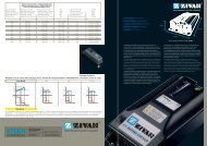
| How to Read Temperature Charts |<br />
Tempearture Rise at Constant Current Charts<br />
Temperature Rise at Constant Current charts show the associated heat rise<br />
as a result of applied current to the connector. An example of the SB ® 50<br />
Temperature Rise chart is included to follow along with this explanation.<br />
The chart is based on an ambient temperature of 25°C (77°F room<br />
temperature). Accordingly if the temperature °C on the Y axis of the chart is at<br />
30°C, the expected total connector temperature would be 55°C.<br />
Temperature (°C)<br />
60<br />
50<br />
40<br />
30<br />
20<br />
SB ® 50<br />
Temperature Rise at Constant Current<br />
Separate curves are shown for #6, #8, #10, and #12 AWG wire. Interpreting<br />
the curves, if 50 amps are applied continuously to the connector, the heat rise<br />
will be 23°C for #6, 35°C for #8, 55°C for #10, and #12 wire is not suitable for<br />
this amperage.<br />
Where T = Temperature, heat rise is expressed as a ΔT°C.<br />
T ambient - T (ambient + heat from applied current) = ΔT°C.<br />
10<br />
0<br />
0 10 20 30 40 50 60 70 80 90<br />
Amperes Applied<br />
6 AWG 8 AWG<br />
10 AWG 12 AWG<br />
- 4 - www.andersonpower.com<br />
All Data Subject To Change Without Notice
Derating vs. Ambient Temperature Charts<br />
Derating vs. Ambient Temperature charts show the maximum amperage<br />
capability of a connector at a given ambient temperature. An example of<br />
the SB ® 50 chart is included to follow along with this explanation.<br />
All data points are based on the maximum operating temperature of the<br />
connector, most often 105°C or 221°F. Accordingly if the temperature °C<br />
on the Y axis of the chart is at 105°C, there is no amperage capability<br />
because the connector housing is already at the maximum operating<br />
temperature.<br />
Temperature (°C)<br />
125<br />
100<br />
75<br />
50<br />
SB ® 50<br />
Derating vs. Ambient Temperature<br />
SECTION 1<br />
Technical Reference<br />
Separate curves are shown for #6, #8, #10, and #12 AWG wire.<br />
Interpreting the curves, at a 75°C ambient temperature the maximum<br />
amperage capability that can be applied continuously to the connector is:<br />
58A for #6, 46A for #8, 37A for #10, and 31A for #12 wire.<br />
25<br />
0 10 20 30 40 50 60 70 80 90 100<br />
Amperes Applied<br />
6 AWG 8 AWG<br />
10 AWG 12 AWG<br />
Notes on Temperature Rise Charts<br />
Note that these charts are constructed using calculations based on actual test data. For this reason the chart<br />
information may vary slightly from the safety agency ratings. Safety agency ratings and compliance with electrical<br />
codes take precedent over these charts. The charts are designed to provide a guideline as to the connectors’ capability.<br />
Actual results can vary based on the specific wire used, crimp tooling and assembly, as well as the environment the<br />
connector is used in.<br />
CSA ratings are based on not exceeding a 30°C temperature rise above ambient or a total temperature of 55°C. This<br />
is considered the maximum temperature to safely handle a connector at. UL ratings can be based on the operating<br />
temperature limit of the connector. Often for APP ® connectors this is 105°C or an 80°C temperature rise above an<br />
ambient temperature of 25°C. To provide a margin of safety, the heat rise charts are limited to a 60°C temperature rise.<br />
| Compatible Wires |<br />
Al<br />
Cu<br />
APP ® connectors are designed to be crimped and/or soldered to multi-stranded copper conductor wires only.<br />
Alternate conductor materials including aluminum should not be used. Aluminum conductors crimped into APP ®<br />
contacts can result in a galvanic reaction occurring between the aluminum wire and the more cathodic metals<br />
used in APP ® contacts including copper, tin, silver, and gold. Additionally softer metals like aluminum flow or<br />
loosen from crimps much easier than copper.<br />
Multi-stranded wire is recommended for all APP ® connectors and is required when crimp terminating wires or when a<br />
connector with flat wiping contact technology is used (such as Powerpole ® and SB ® ). Solid wires do not adequately<br />
compress and retain in crimp barrels after being crimped. For this reason if solid wire is used, it should be with solder<br />
termination only.<br />
Solid wires also do not flex and bend as easily as multi-stranded equivalents and can act as a lever arm and impede<br />
or alter the natural state of a flat wiping contact in the housing. This impediment or alteration to the flat wiping contact’s<br />
natural state can cause intermittency and shorts as well as higher resistance and temperature at a given amperage<br />
than is shown in APP ® specifications. Mating and unmating forces may also be impacted.<br />
All Data Subject To Change Without Notice<br />
www.andersonpower.com - 5 -
| Different Contact Technologies |<br />
SECTION 1<br />
Technical Reference<br />
Flat Wiping:<br />
• Same contacts on the “male” and “female” side reduce inventory costs and increase ease of assembly.<br />
• Low resistance connection has a large conducting surface and a high normal force in comparison to typical pin<br />
and socket contacts.<br />
• Sacrificial tip confines damage to non-conducting area when mating or breaking under load.<br />
• Raised surface on the mating side of the contacts secures the connector in the mated condition, limiting the<br />
need for latching on outer housings.<br />
• Over wiping design cleans the mating surface when mating and unmating.<br />
- VS -<br />
Solid line<br />
of electrical<br />
contact.<br />
Flat Wiping Technology<br />
Select points of<br />
electrical contact.<br />
Pin & Socket Technology<br />
Pin & Socket:<br />
• Different contacts on male and female sides. Female socket contacts are typically more expensive than the<br />
simple geometries of the pin contacts.<br />
• Often higher resistance than flat wiping connectors of the same wire size and plating due to the reduced mating<br />
surface area and lower normal force. Gold plating often used to compensate and minimize resistance.<br />
• Best for compact connection needs such as signal and low power due to static position in housings and<br />
symmetrical shape.<br />
• Socket contacts can catch and hold debris inside the socket body causing mating problems.<br />
| Use of APP ® Connectors in Applications Exceeding 600V |<br />
The approved voltage ratings for APP ® connectors are usually limited by the category under which a safety agency<br />
such as UL approves our connector for use. UL typically defers to National Electric Code (NEC) on the voltage limitations<br />
for any given device our connector could be used in. For most common applications NEC restricts voltage to a maximum<br />
of 600V AC or DC which is what our connector voltage ratings are based on.<br />
To achieve UL 1977 approval for a 600V rating, we test our connectors for dielectric withstanding voltage. The connector<br />
is tested at 2 times the rated voltage of 600V plus 1000V or 2200VAC for 1 minute. For applications exceeding 600V,<br />
UL / NEC / IEC may require application specific review for creepage and clearance resistance.<br />
| Frequently Asked Questions |<br />
Q: Can I cross mate low and high mating force contacts?<br />
A: Yes, however this would not be a connection solution we have tested for safety agency approval. Additionally the<br />
contacts may wear at an accelerated rate causing the mating cycle rating to be reduced. The mating and unmating<br />
force expected would be somewhere in between the high and low mating force specification.<br />
Q: Can I crimp multiple wires into 1 crimp barrel?<br />
A: Yes, however this would not be a connection solution we have tested for safety agency approval. Particular care<br />
should be used that the bundle of wires do not interfere with the movement of the contact in the housing during mating<br />
and unmating (see maximum wire O.D. specification). The total circular mils of all conductor stands should be within<br />
+ or – 5% of the wire size the contact is intended for. Twist the conductor strands together and crimp using APP ®<br />
tooling with range taking capabilities such as the 1368 series. To crimp with other APP ® recommended tools, contact<br />
customer service for the recommended setting or die and locator combination.<br />
- 6 - www.andersonpower.com<br />
All Data Subject To Change Without Notice
Q: Will the crimp tool I have for standard color-coded lugs, Mil Spec contacts, or another connector<br />
manufacturer, work for crimping APP ® contacts?<br />
A: No. APP ® contacts generally do not conform to standard crimp barrel dimensions used for lugs, Mil Spec contacts,<br />
or other connector manufacturers. The tooling recommended by APP ® must be used to ensure the performance<br />
designed by APP ® is achieved. Alternate tooling will void APP ® warranties and can affect safety agency approvals. In<br />
some instances Mil Spec tools are approved for crimping contacts with the dies and locators recommended by APP ® .<br />
See tooling charts for specific instances, or contact customer service for more information.<br />
SECTION 1<br />
Technical Reference<br />
Q: Can metric sized wires be used with APP ® contacts?<br />
A: Yes. The majority of our crimp tooling recommendations are based on testing and verification we have performed<br />
with AWG sized cables. Metric cables of the same or slightly smaller circular mils equivalent to the AWG wire recommended<br />
can typically be successfully terminated in APP ® contacts. There is a wire conversion chart at the end of this catalog<br />
section that can be used as a reference when converting AWG to mm² sizes. The 1368 series crimp tooling has a<br />
range taking capability that produces a reliable crimp with metric equivalents of AWG cables. Please contact customer<br />
service for metric tooling recommendations for other APP ® crimp tools.<br />
Q: Are APP ® connectors suitable for use in applications where the voltage exceeds 600V AC/DC?<br />
A: Possibly. See “Use of APP ® Connectors in Applications Exceeding 600V”, contact customer service with further<br />
questions.<br />
Q: How do Powerpole ® and Multipole connectors stay securely mated without latches?<br />
A: The proven flat wiping technology used in these connectors features a detent or bump in the contact surface along<br />
with powerful stainless steel springs that hold the connectors in the mated position. High mating force contacts have<br />
a detent that is raised higher than low mating force contacts. The higher the detent, the more force is required to mate<br />
and unmate the contacts. In many applications the detent and spring force is enough to securely hold the connectors<br />
in the mated position without the need for latches. Latching shells, clips, or other external devices can be used to<br />
secure flat wiping connectors in applications where shock, vibration, or cable strain may overcome the inherent force<br />
holding the connectors together.<br />
Q: How does APP ® ’s genderless connector design work to make a mated pair.<br />
A: Genderless Powerpole ® and Multipole housings do not have a male(pin) and female(socket) side. For wire-to-wire<br />
applications the exact same housings and contacts are used on both sides of the mated pair. If your application calls<br />
for wire-to-PCB or wire-to-busbar connections then different contacts and possibly housings will be required on each<br />
half (similar to male and female connectors).<br />
To make a mated pair of Powerpole ® or Multipole connectors simply assemble the connectors closely following the<br />
assembly instructions. After each connector half is fully assembled take one half and flip it over. The two halves will<br />
mate together. Multi-row Powerpole ® assemblies will need to be stacked in mirror images of each other to properly<br />
mate the correct circuits. This information is detailed at the beginning of the Powerpole ® section.<br />
All Data Subject To Change Without Notice<br />
www.andersonpower.com - 7 -
| Touch Safety & Ingress Protection (IP) |<br />
SECTION 1<br />
Technical Reference<br />
UL 1977 Section 10.2:<br />
Typically required for applications where the connector is external to the end device and operating over 30V or 200A,<br />
where wet conditions may be present (600V category).<br />
Testing is performed using a probe that mimics a child’s finger. All features of the connector are tested for live parts<br />
in the unmated state (no pressure applied). A smaller 3 mm probe is then applied in the mated state to test for live<br />
parts. Note that some applications may require the connector to not expose live parts to the 3 mm probe in the mating<br />
interface.<br />
IEC 60950:<br />
From the standard for Information Technology Equipment Safety, the requirements are harmonized with UL1950. Typically<br />
required for commercial and industrial applications where operators may need some degree of protection while acessing<br />
or servicing equipment.<br />
Testing is performed using a probe that mimics an adult finger. All features of the connector are tested for live parts in<br />
the unmated state with 30 N of force applied to the probe.<br />
IEC 60529:<br />
Standard for Degrees of Protection Provided by Enclosures is harmonized with EN 60529.<br />
Protection degree number is assigned to both solids and liquids in that order. For example: a connector with an IP20 rating<br />
is protected against fingers, but has no protection against ingress of liquids. APP ® takes a conservative approach in rating<br />
our connectors against liquid ingress and consider any meaningful water ingress to have a harmful effect.<br />
Protection<br />
Degree<br />
Solids (First Digit)<br />
Liquids (Second Digit)<br />
Description Protected Against Description Protected Against<br />
0<br />
1 > 50 mm<br />
2 > 12.5 mm<br />
Not Protected<br />
Large body part such as<br />
back of hand<br />
Adult fingers or similarly<br />
sized objects<br />
Vertically dripping water<br />
(no harmful effect)<br />
Tilted 15 degrees up<br />
dripping water<br />
(no harmful effect)<br />
Not Protected<br />
Duration: 10 minute<br />
Water: 1 mm / minute rainfall<br />
Pressure: N/A<br />
Duration: 10 minute<br />
Water: 3 mm / minute rainfall<br />
Pressure: N/A<br />
3 > 2.5 mm<br />
Typical screw drivers or<br />
large wires<br />
Water spray up to 60<br />
degree angle<br />
(no harmful effect)<br />
Duration: 5 minute<br />
Water: 0.7 liter / minute<br />
Pressure: 80-100 kN/m²<br />
4 > 1 mm<br />
Small pointy tools and<br />
small wires<br />
Water splash from<br />
any direction<br />
(no harmful effect)<br />
Duration: 5 minute<br />
Water: 10 liter / minute<br />
Pressure: 80-100 kN/m²<br />
5 Dust protected<br />
Complete physical<br />
protection, no functional<br />
interference from dust<br />
Water jet from any<br />
direction<br />
(no harmful effect)<br />
Duration: 3+ minute<br />
Water: 12.5 liter / minute<br />
Pressure: 30 kN/m² @ 3 m distance<br />
6 Dust sealed<br />
Complete physical<br />
protection and sealed<br />
from dust ingress<br />
Strong water jet from<br />
any direction<br />
(no harmful effect)<br />
Duration: 3+ minute<br />
Water: 100 liter / minute<br />
Pressure: 100 kN/m² @ 3 m distance<br />
7<br />
N/A<br />
No ingress of water<br />
in harmful quantity<br />
when immersed up<br />
to 1 m depth<br />
Duration: 30 minute<br />
Water: Immersion<br />
Pressure: 1 m depth<br />
8<br />
No ingress of water<br />
in harmful quantity<br />
when subject to tests<br />
in excess of condition 7<br />
Duration: Mfg. specified<br />
Water: Immersion<br />
Pressure: 1+ m depth. Mfg. specified<br />
- 8 - www.andersonpower.com<br />
All Data Subject To Change Without Notice
| Preventative Maintenance |<br />
Damaged connectors, contacts and cables may present hazards, resulting in inefficient battery and charger operation.<br />
To avoid these problems, conduct the following maintenance checks at least once annually. When you see a problem,<br />
take corrective action immediately.<br />
1. Dirty Connectors<br />
When engaged and disengaged, the contact surfaces of Anderson SB ® Connectors “over wipe,” thus providing<br />
a self cleaning action. To ensure the continued benefit of this feature, clean the contact surfaces and lubricate<br />
the connector. Use a “white” lithium grease, which may be obtained from hardware stores and automotive parts<br />
suppliers.<br />
SECTION 1<br />
Technical Reference<br />
2. Melting Connectors<br />
Connector housings overheat and melt for many reasons. To prevent this:<br />
A. Examine the crimp between cable and contact. Ensure the crimp tooling recommended by APP ® has been<br />
used. Improper crimping, corrosion, and broken wires result in unnecessary resistance causing the contact<br />
to heat up.<br />
B. Check contact surfaces for signs of “pitting” caused by dirt or disengaging connectors under load. One<br />
badly pitted contact, particularly in a connector attached to a battery charger, can lead to pitting on surfaces<br />
of other contacts. If not corrected, this can result in an epidemic of bad connectors throughout a fleet of electric<br />
vehicles and in chargers and batteries.<br />
C. Check to see if batteries are being disconnected while the charger is still on. This causes the contacts to arc<br />
at the tips, resulting with progressive pitting and silver removal from tip to crown. If this practice is occurring,<br />
discontinue it now to avoid major repairs in the future.<br />
3. Other Conditions<br />
If any of the following conditions exist, the connector housing, contact and/or cable should be replaced immediately.<br />
A. Housing: Cracks, missing pieces, evidence of excessive heat, discoloration. You may consider replacing the existing<br />
housing with a Chemical Resistant equivalent for improved durability against UV rays and common solvents and<br />
hydrocarbons.<br />
B. Contacts: Pitting, burns, corrosion, excessive wear, cracked crimp barrels,<br />
discoloration.<br />
C. Cable: Exposed copper near housing, cracked cable, peeling or frayed insulation.<br />
D. Handles: Loose attachment and signs of damage as missing or loose hardware<br />
and cracked or broken plastic (Handles should be used for connectors that are<br />
hard to reach or move.)<br />
E. Cable Clamps: Loose attachments, signs of abraded cable jacket, missing<br />
or loose hardware. (Cable clamps should be used to relieve strain on<br />
unmounted cable.)<br />
A<br />
Uncrimped Good<br />
Contact<br />
Damaged<br />
Contact<br />
B<br />
All Data Subject To Change Without Notice<br />
www.andersonpower.com - 9 -
SECTION 1<br />
Glossary<br />
Amp / Ampere: Measurement increment of electric current. Abbreviated<br />
as “I”.<br />
Applicator: A semi-automatic termination machine consisting of an<br />
upper and lower half that is used to crimp contacts onto wire. Used in<br />
conjunction with an electrical/ mechanical press.<br />
AWG: American Wire Gauge. A standard system for designating wire<br />
diameters.<br />
Blindmate: To join two connector halves in a normal engaging mode<br />
without visual orientation.<br />
Busbar: Three dimensional constructions enabling electrical distribution<br />
of current in power electronic modules. Typically constructed of copper,<br />
busbars are most frequently used in power dense applications<br />
where the busbar offers a cost or space savings over wire.<br />
Color Coding: A system of identification for terminals and related devices.<br />
Contact Resistance: The electrical resistance of metallic surfaces<br />
at their interface in the contact area under specified conditions when<br />
carrying a specified test current.<br />
Contact Retention: Minimum axial load in either direction which a<br />
contact must withstand while remaining firmly fixed in its normal position<br />
within a housing.<br />
Crimp Retention: The axial load which a contact can withstand without<br />
separation from the wire.<br />
Crimp Termination: A connection in which a metal sleeve is secured<br />
to a conductor by mechanically deforming the sleeve with presses or<br />
automated crimping machines, eliminating the need for solder. Not<br />
suitable for solid (non-stranded wires).<br />
CSA: Canadian Standards Association, a safety standard writing and<br />
testing organization.<br />
Cycle Controlled: To determine if repetitive on/off conditions result<br />
in degrading the contact system which may lead to failures such as<br />
“thermal run away”.<br />
Detent: A bump or raised section projecting from the surface of a contact<br />
for keeping the contact in position relative to another and released by<br />
greater force.<br />
Dielectric Strength (Withstanding Voltage): The highest potential<br />
difference (voltage) that an insulation material of given thickness can<br />
withstand for a specified time without occurrence of electrical breakdown<br />
through its bulk.<br />
Finger Proof: A connector intended for usage external to the end<br />
equipment shall have live parts protected against exposure to contact<br />
by persons when assembled, installed, and mated as intended, as<br />
determined by UL Articulated probe.<br />
Flammability: The measure of a material’s ability to support combustion.<br />
Often tested per UL94.<br />
Flat Wiping: The sliding action which occurs when contacts are mated.<br />
Wiping has the effect of removing small amounts of contamination from<br />
the contact surfaces, thus establishing better conductivity.<br />
Genderless: See “Hermaphroditic”<br />
Heat Rise: Temperature rise associated with the electrical load applied<br />
to a mated connection.<br />
Hermaphroditic (Genderless) Connector: A connector in which both<br />
mating members are exactly alike at their mating face. There are no<br />
male or female members, but designs provide correct polarity.<br />
Hot Plug / Hot Swap: Live connector insertion / extractions.<br />
IEC: International Electrotechnical Commission, a standard writing<br />
organization.<br />
Insulation Resistance: Ratio of applied voltage to the total current<br />
between the two electrodes in contact with a specific insulation.<br />
IP: Ingress Protection, a standard per IEC 60529 for measurement of<br />
ingress for solids and liquids into an enclosure.<br />
Locator / Positioner: Device for positioning contacts into crimping dies.<br />
Make-First / Break-Last (Premate): Sequencing of contact(s) so<br />
that they engage prior to the main power contacts. Typically used<br />
for ground / positive earth / neutral positons as a protective measure<br />
against excess currents, short-circuits, and ground faults.<br />
Make-Last / Break-First (Postmate): Sequencing of contact(s) so that<br />
they engage after the main power contacts. Typically used for signal or<br />
auxiliary power positions to ensure communications are not started or<br />
power circuits switched on until the power contacts are fully engaged.<br />
Mating Force: Force required to join two connector halves in a normal<br />
engaging mode.<br />
Modular: Refers to similar parts or modules used as building blocks. A<br />
modular connector is one in which similar or identical sections can be<br />
assembled together to provide the appropriate connector type or size<br />
for the application.<br />
Ohms: Measurement increment of resistance.<br />
Operating Temperature Range: Connector temperature rating<br />
established by materials used, plastic, finish, and the base metal.<br />
Applying an electrical load will result in a temperature rise that is<br />
additive to the operating ambient.<br />
PCB: Acronym for Printed Circuit Board<br />
Polarization: A technique of eliminating symmetry so that parts may<br />
only be mated one way.<br />
- 10 - www.andersonpower.com<br />
All Data Subject To Change Without Notice
Pulse (Surge) Current: Highest instantaneous current that will run<br />
through a system.<br />
REACH: The European Community Regulation on chemicals and their<br />
safe use. It deals with the Registration, Evaluation, Authorization and<br />
Restriction of Chemical substances.<br />
Reducing Bushing: Separate tubular sleeve used to downsize the<br />
diameter of a crimp barrel to accept a smaller size wire.<br />
Reeled Contacts: Contacts attached to a feeder strip for use in a high<br />
volume crimping tool.<br />
Resistance: The opposition to the passage of an electric current<br />
through that element. Abbreviated as “R”.<br />
RoHS: Restriction of Hazardous Substances Directive. The European<br />
directive on the restriction of the use of certain hazardous substances<br />
in electrical and electronic equipment.<br />
Sacrificial Tip: An area of a contact system that absorbs electric arching<br />
to limit damage to the actual mating surface of the contacts.<br />
Self-Wiping: The sliding action which occurs when contacts are mated.<br />
Wiping has the effect of removing small amounts of contamination<br />
from the contact surfaces, establishing better conductivity.<br />
Spring Loaded: A means of providing contact normal force with the<br />
use of a mechanical spring.<br />
Storage Battery: A voltaic battery consisting of two or more storage<br />
cells. Energy is accumulated by chemical activity in the charging<br />
process and released on demand in the form of electric current.<br />
Strain Relief: A means of termination or installation that reduces the<br />
transfer of mechanical stress from the conductor.<br />
Termination: Means of joining contacts to a conductor.<br />
Touch Safe: See “Finger Proof”<br />
Turret / Positioner: See “Locator”<br />
TUV: The TÜV Rheinland Group is provider of technical services that<br />
certifies products to standards written by other organizations.<br />
UL: Underwriters Laboratory, a safety standard writing and testing<br />
organization.<br />
Volts: Measurement increment of electric potential. Abbreviated as “E”.<br />
VDE: A German standard writing and testing organization responsible<br />
standards and safety specifications covering the areas of electrical<br />
engineering, electronics and information technology.<br />
Watt: Measurement increment of electric power. Abbreviated as “W”.<br />
SECTION 1<br />
Glossary<br />
All Data Subject To Change Without Notice<br />
www.andersonpower.com - 11 -
SECTION 1<br />
Engineering Reference<br />
| Conversion Chart for American Wire Guage to Metric System |<br />
Approximate<br />
AWG Metric Circ. Equivalent Wire Diameter<br />
Size mm² Mils Circ.Mils in. mm<br />
Approximate<br />
AWG Metric Circ. Equivalent Wire Diameter<br />
Size mm² Mils Circ.Mils in. mm<br />
- 0.5 - 937 0.032 0.81 1/0 - 106mcm* - 0.373 9.46<br />
20 - 1020 - 0.036 0.91 2/0 - 133mcm* - 0.419 10.60<br />
- 0.75 - 1480 0.039 0.99 - 70 - 138.1mcm 0.430 10.90<br />
18 - 1620 - 0.046 1.16 3/0 - 168mcm* - 0.471 12.00<br />
- 1 - 1974 0.051 1.30 - 95 - 187.5mcm 0.504 12.80<br />
16 - 2580 - 0.051 1.29 4/0 - 212mcm* - 0.528 13.40<br />
- 1.5 - 2960 0.063 1.60 - 120 - 237.8mcm 0.567 14.40<br />
14 - 4110 - 0.073 1.84 - - 250mcm - 0.575 14.60<br />
- 2.5 - 4934 0.081 2.06 - 150 300mcm - 0.630 16.00<br />
12 - 6530 - 0.092 2.32 - - 350mcm - 0.681 17.30<br />
- 4 - 7894 0.102 2.59 - 185 - 365.1mcm 0.700 17.80<br />
10 - 10380 - 0.116 2.93 - - 400mcm - 0.728 18.50<br />
- 6 - 11840 0.126 3.21 - 240 - 473.6mcm 0.801 20.30<br />
8 - 16510 - 0.146 3.70 - - 500mcm - 0.814 20.70<br />
- 10 - 19740 0.162 4.12 - 300 - 592.1mcm 0.891 22.60<br />
6 - 26240 - 0.184 4.66 - - 600mcm - 0.893 22.70<br />
- 16 - 31580 0.204 5.18 - - 700mcm - 0.964 24.50<br />
4 - 41740 - 0.232 5.88 - - 750mcm - 0.999 25.40<br />
- 25 - 49340 0.260 6.60 400 - 789.4mcm 1.026 26.10<br />
2 - 66360 - 0.292 7.42 - - 800mcm - 1.032 26.20<br />
- 35 - 69070 0.305 7.75 - 500 986.8mcm 1.152 29.30<br />
1 - 83690 - 0.332 9.43 - - 1000mcm - 1.153 29.30<br />
- 50 - 98680 0.365 9.27 - 625 - 1233.7mcm 1.287 32.70<br />
* Rounded for simplicity<br />
NOTE: The above wire diameters and circular mils are based on an average of the most commonly available wires. The wire<br />
manufacturer’s specification should be referenced for information specific to the wire being used.<br />
- 12 - www.andersonpower.com<br />
All Data Subject To Change Without Notice
| Volts • Amps • Ohms • Watts Conversion |<br />
SECTION 1<br />
Engineering Reference<br />
WR<br />
E<br />
R<br />
E<br />
I<br />
E I<br />
W<br />
I<br />
W<br />
R<br />
W<br />
I²<br />
I² R<br />
IR<br />
W<br />
E<br />
E²<br />
W<br />
E²<br />
R<br />
Volts =<br />
Watts x Ohms<br />
Amperes =<br />
Volts<br />
Ohms<br />
Ohms = Volts<br />
Amps<br />
Watts = Volts x Amps<br />
Volts = Watts<br />
Amps<br />
Amperes =<br />
Watts<br />
Ohms<br />
Ohms = Watts<br />
Amps²<br />
Watts = Amps ² x Ohms<br />
Volts = Amps x Ohms<br />
Amperes =<br />
Watts<br />
Volts<br />
Ohms = Volts²<br />
Watts<br />
Watts = Volts²<br />
Ohms<br />
Wattage Varies Directly as a Ratio of Voltages Squared.<br />
W² = W¹<br />
E²<br />
x ²<br />
E¹<br />
3 Phase Amperes =<br />
Total Watts<br />
Volts x 1.732<br />
All Data Subject To Change Without Notice<br />
www.andersonpower.com - 13 -
| Standard to Metric Conversions |<br />
SECTION 1<br />
Engineering Reference<br />
Symbol<br />
Approximate Conversions<br />
From: Standard / US Customary<br />
To: SI / Metric Units<br />
When<br />
You<br />
Know<br />
Multiply<br />
By To Find Symbol<br />
LENGTH<br />
Symbol<br />
Approximate Conversions<br />
From: SI / Metric Units<br />
To: Standard / US Customary<br />
When<br />
You<br />
Know<br />
Multiply<br />
By To Find Symbol<br />
LENGTH<br />
in inches 25.4 millimeters mm mm millimeters 0.039 inches in<br />
ft feet 0.305 meters m m meters 3.28 feet ft<br />
AREA<br />
AREA<br />
in 2<br />
square<br />
inches 645.2<br />
square<br />
mm 2 millimeters 0.0016 square<br />
millimeters mm 2 inches<br />
in 2<br />
ft 2 square feet 0.093<br />
square<br />
meters m 2 m 2 square<br />
meters<br />
10.764 square feet ft 2<br />
VOLUME<br />
VOLUME<br />
fluid<br />
mL milliliters 0.034 fluid fl oz<br />
fl oz ounces 29.57 milliliters mL<br />
ounces<br />
gal gallons 3.785 liters L L liters 0.264 gallons gal<br />
ft 3 cubic feet 0.028<br />
cubic<br />
meters m 3 m3 cubic<br />
meters<br />
35.314 cubic feet ft3<br />
MASS<br />
MASS<br />
oz ounces 28.35 grams g g grams 0.035 ounces oz<br />
lb pounds 0.454 kilograms kg kg kilograms 2.202 pounds lb<br />
TEMPERATURE<br />
TEMPERATURE<br />
o F Fahrenheit (F-32) x 5 / Celsius o C<br />
o C Celsius 1.8C + 32 Fahrenheit<br />
o F<br />
9<br />
or<br />
(F-32) / 1.8<br />
FORCE and PRESSURE or STRESS<br />
FORCE and PRESSURE or STRESS<br />
lbf poundforce 4.45 newtons N N newtons 0.225 poundforce lbf<br />
lbf/in 2<br />
poundforce<br />
per square<br />
inch<br />
6.89 kilopascals kPa kPa kilopascals 0.145 poundforce<br />
per square<br />
inch<br />
lbf/in 2<br />
- 14 - www.andersonpower.com<br />
All Data Subject To Change Without Notice
| Scratch Pad |<br />
SECTION 1<br />
Engineering Reference<br />
All Data Subject To Change Without Notice<br />
www.andersonpower.com - 15 -
®<br />
Powerpole ® Connectors<br />
- PP15 to PP180<br />
SECTION 2<br />
Powerpole ® Family<br />
This versatile connector series invented by Anderson Power<br />
Products ® meets a wide range of power connection needs.<br />
There are four basic housing sizes in the Powerpole ®<br />
product family that allow specific amperage or wire size<br />
needs to be filled in the most compact footprint. Powerpole ®<br />
can handle up to 350 amperes per pole and accommodate<br />
wire ranges of #20 AWG (0.5 mm²) to 3/0 (70 mm²). A wide<br />
range of colored housing options can be stacked together to<br />
create a proven reliable custom connector. These housings<br />
can be used with different contacts to create wire-to-wire,<br />
wire-to-board, or wire-to-busbar connections. The<br />
Powerpole ® combines high quality materials and a cost<br />
effective innovative design to allow powerful versatility.<br />
Stackable Modular Housings<br />
Available in four sizes to right<br />
size your connection need<br />
Color Coded Housings<br />
Help ensure that connectors<br />
are assembled and mated<br />
correctly<br />
Genderless Housings<br />
Provide simplified assembly<br />
and minimize the number of<br />
components<br />
Low Resistance Connection<br />
Silver or tin plated contacts<br />
inside housings that strongly<br />
force the contacts together<br />
Self Securing Design<br />
Stainless steel springs create<br />
a robust force between the<br />
contacts that holds the connector<br />
in the mated condition,<br />
but allows it to be quickly disconnected<br />
Hot Plugging AC or DC<br />
Contacts feature a sacrificial<br />
tip that allow high current<br />
circuit interrupt<br />
Connection Versatility<br />
Contacts for wire, PCB,<br />
or busbar all fit into the<br />
same housings<br />
- 16 - www.andersonpower.com<br />
All Data Subject To Change Without Notice
| POWERPOLE FAMILY SELECTION GUIDE |<br />
Powerpole ® Size PP15 to 45 Page # PP75 Page # PP120 Page # PP180 Page #<br />
Connector Types Standard 20 Standard 30 Standard 36 Standard 39<br />
Finger Proof 20 Locking 31 Busbar 40<br />
PCB 21 Busbar 31<br />
Ground<br />
Power Pak<br />
21 PCB 31<br />
23<br />
Amps (UL) Per Pole 0 to 55 120 240 350<br />
Volts (UL) Per Pole 600 600 600 600<br />
Wire Gauge (AWG) 20 - 10 16 - 6 6 - 1/0 10 - 3/0<br />
Wire Gauge (mm²) 0.05 - 6.0 1.3 - 13.3 13.3 - 53.5 5.3 - 85.0<br />
Number of<br />
Power Circuits 1 / Stackable 1 / Stackable 1 / Stackable 1 / Stackable<br />
Ground<br />
●<br />
PCB Mount ● ●<br />
Busbar ● ●<br />
SECTION 2<br />
Powerpole ® Family<br />
Panel Mount ● ● ● ●<br />
Blind Mate<br />
Powerpole ® Pak<br />
Hot Plug ● ● ● ●<br />
Touch Safe<br />
●<br />
Polarized Housing ● ● ● ●<br />
Latching<br />
Strain Relief<br />
Powerpole ® Pak<br />
Powerpole ® Pak<br />
Actual Size - Connector Half<br />
............................... Powerpole ® Housings ...............................<br />
PP15/45 PP75 PP120 PP180<br />
All Data Subject To Change Without Notice<br />
www.andersonpower.com - 17 -
Powerful Versatility<br />
- Create Your Own Custom Connector from Durable Proven Components<br />
Powerpole ® connectors can be easily customized to each power connection need. Choose from a wide range of<br />
colored housings and stack them together into a multiple position connection. Durable silver or tin plated contacts<br />
crimp and poke into housings and are available for a broad range of wire sizes. PCB and busbar contacts can also<br />
be simply snapped into place using the same housings. Pre-mate ground / power housings and contacts can be<br />
used for safety or sequencing and stack along with standard housings.<br />
How to Create Mating Blocks of Stacked Powerpole ® Connectors<br />
A Single Row Assembly such as the 1x3 shown below will mate to itself. If an assembly has more than one row<br />
such as the Two Row Assembly 2x1 shown below, then a different mirror image mating assembly is required.<br />
Single Row Assembly 1x3<br />
Two Row Assembly 2x1<br />
SECTION 2<br />
Powerpole ® Family<br />
To Create a Mirror Image Mating Assembly:<br />
When mating blocks are viewed with their hoods in the respective orientation (down or up), the column position of<br />
connectors is unchanged. The rows themselves are mirror images of each other. So in the below example, what<br />
is column 1 on side A, is column 3 on side B.<br />
Side A Hood Down<br />
Column 1<br />
Column 2<br />
Column 3<br />
Column 1<br />
Column 2<br />
Column 3<br />
Side B Hood Up<br />
Hood Down<br />
A B C<br />
C B A<br />
Hood Up<br />
D E F<br />
F E D<br />
G H I<br />
I H G<br />
- 18 - www.andersonpower.com<br />
All Data Subject To Change Without Notice
Use the Same Housings for Wire, PCB, or Busbar Connections<br />
The Powerpole ® connection system allows the same housings to hold different contacts for terminating to wire,<br />
printed circuit boards, or busbars. See some of the many ways Powerpole ® components can be assembled to<br />
create a custom connection solution.<br />
Wire-to-Wire<br />
SECTION 2<br />
Powerpole ® Family<br />
Wire-to-PCB<br />
Wire-to-Busbar<br />
All Data Subject To Change Without Notice<br />
www.andersonpower.com - 19 -
Powerpole ® Connectors<br />
- PP15 to PP45 :<br />
up to 55 Amps<br />
PP15-45 series are the smallest Powerpole ® housings. They can be<br />
used for wire-to-wire or wire-to-board applications. Wire sizes from<br />
#20 AWG (0.5 mm²) to #10 (6 mm²) offer power capabilities up to 55<br />
amps per pole. Finger proof housings and the ability to incorporate<br />
first-mate last-break ground connectors enhance the capabilities of<br />
this Powerpole ® series.<br />
High Power Density<br />
• Up to 55 amps in a compact footprint<br />
Wire-to Wire & Wire-to-Board Configurations<br />
• Wire & PCB contacts can be used in the same housings<br />
SECTION 2<br />
Powerpole ® PP15 to 45<br />
| PP15-45 ORDERING INFORMATION |<br />
Finger Proof Housings Available<br />
• Protects against accidental contact with live circuits<br />
PP15-45 Finger Proof Housings<br />
Improved on the original APP ® design by adding ribs to mating interface to protect against accidental<br />
contact with live circuits. Meets the requirements of UL1977 section 10.2 and is rated IP20. Will not<br />
mate with standard housings.<br />
Description ------------ Part Numbers ------------<br />
Minimum Quantity ... 2,500 200 .....<br />
Red 1327FP-BK 1327FP<br />
Green 1327G5FP-BK 1327G5FP<br />
Black 1327G6FP-BK 1327G6FP<br />
White 1327G7FP-BK 1327G7FP<br />
Blue 1327G8FP-BK 1327G8FP<br />
Yellow 1327G16FP-BK 1327G16FP<br />
Finger Proof<br />
Rib Feature<br />
PP15-45 Finger Proof & Standard & Ground Housing Dimensions<br />
[ 7.9 ] Front View<br />
0.31<br />
[ 26.6 ]<br />
0.97<br />
Mated Length<br />
[ 7.9 ]<br />
0.31<br />
[ 41.2 ]<br />
1.62<br />
[ 8.4 ]<br />
0.33<br />
PP15-45 Standard Housings<br />
The original housing design has an open interface and is available<br />
in a wide array of colors. Will not mate with finger proof housings.<br />
Description ------- Part Numbers ------<br />
Minimum Quantity ... 2,500 200 ...<br />
Red 1327-BK 1327<br />
Green 1327G5-BK 1327G5<br />
Black 1327G6-BK 1327G6<br />
White 1327G7-BK 1327G7<br />
Blue 1327G8-BK 1327G8<br />
Yellow 1327G16-BK 1327G16<br />
Orange 1327G17-BK 1327G17<br />
Gray 1327G18-BK 1327G18<br />
Brown 1327G21-BK 1327G21<br />
Pink 1327G22-BK 1327G22<br />
Purple 1327G23-BK 1327G23<br />
45A Premate Ground Housings<br />
Green housings are keyed to prevent accidental mating<br />
with standard or finger proof Powerpole ® housings.<br />
Description ------- Part Number -------<br />
Minimum Quantity ... 2,500 200 ...<br />
Green 1827G1-BK 1827G1<br />
PP15-45 Tin Plated Power Contacts<br />
Offer cost effective performance up to 1,500 mating cycles. See specifications and temperature<br />
charts for amperage ratings by wire size.<br />
Dimensions<br />
Mating Loose Piece Reeled - A -<br />
Barrel AWG mm² Force -------- Part Numbers ------- inches mm<br />
Minimum Quantity ....................................... 200 5,000 .........................<br />
Open 14 to 10 K* 2.1 to 5.3 High 269G3-LPBK 269G3 0.21 5.33<br />
Open 14 to 10 K* 2.1 to 5.3 Low 261G2-LPBK 261G2 0.20 5.08<br />
Open 14 to 10 SF* 2.1 to 6.0 High 201G1H-LPBK 201G1H 0.24 6.10<br />
Open 14 to 10 SF* 2.1 to 6.0 Low 200G1L-LPBK 200G1L 0.24 6.10<br />
Open 16 to 12 1.3 to 3.3 High 269G1-LPBK 269G1 0.18 4.57<br />
Open 16 to 12 1.3 to 3.3 Low 261G1-LPBK 261G1 0.18 4.57<br />
Open 20 to 16 0.52 to 1.3 High 269G2-LPBK 269G2 0.16 4.06<br />
Open 20 to 16 0.52 to 1.3 Low 262G1-LPBK 262G1 0.16 4.06<br />
Open 20 to 16 SF* 0.52 to 1.5 Low 200G2L-LPBK 200G2L 0.20 5.08<br />
Open Barrel Contact<br />
[ 17.27 ]<br />
0.68<br />
[ 3.81 ]<br />
0.15<br />
A<br />
[ 6.35 ]<br />
0.25<br />
K* - For #10 AWG class K stranded wire or smaller. For larger wires use superflex contacts.<br />
SF*- Indicates wires with high stranding such as Super Flex.<br />
- 20 - www.andersonpower.com<br />
All Data Subject To Change Without Notice
PP15-45 Silver Plated Power Contacts<br />
Maximize performance by offering up to 10,000 mating cycles and are recommended for circuit interrupt or<br />
hot plug applications. See specifications and temperature charts for amperage ratings by wire size. Only closed<br />
barrel contacts are suitable for soldering.<br />
Dimensions<br />
Mating Loose Piece Reeled - A - - B -<br />
Barrel AWG mm² Force -------- Part Number --------- Part Number inches mm inches mm<br />
Minimum Quantity .......................................... 5,000 200 5,000 .................................................<br />
Open 14 to 10 K* 2.1 to 5.3 Low - 261G3-LPBK 261G3 0.20 5.08 - -<br />
Open 14 to 10 SF* 2.1 to 6.0 High - - 201G3H 0.24 6.10 - -<br />
Open 14 to 10 SF* 2.1 to 6.0 Low - 200G3L-LPBK 200G3L 0.24 6.10 - -<br />
Open 16 to 12 1.3 to 3.3 Low - 261G4-LPBK 261G4 0.18 4.57 - -<br />
Open 20 to 16 0.52 to 1.3 Low - 262G2-LPBK 262G2 0.16 4.06 - -<br />
Open 20 to 16 SF* 0.52 to 1.5 Low - - 200G4L 0.20 5.08 - -<br />
Closed 16 to 12 1.3 to 3.3 Low 1331-BK 1331 - 0.15 3.81 0.10 2.54<br />
Closed 20 to 16 0.52 to 1.3 Low 1332-BK 1332 - 0.12 3.05 0.07 1.78<br />
K* - For #10 AWG class K stranded wire or smaller. For larger wires use superflex contacts.<br />
SF*- Indicates wires with high stranding such as Super Flex.<br />
45A Premate Ground Wire Contacts<br />
Tin or silver plated contacts are rated for ground or power. Hand tools are available for loose piece<br />
contacts. Reeled contacts can be used with high volume press and applicator tooling. Tin contacts<br />
are rated for up to 1,500 mating cycles. Silver contacts are rated up to 10,000 mating cycles.<br />
Reeled<br />
Mating Loose Piece Part<br />
Type AWG mm² Force - Part Numbers - - Numbers -<br />
Minimum Quantity ............................................. 200 5,000 .....<br />
Open, Tin 14 to 10 2.1 to 6.0 Low 1830G1-LPBK 1830G1<br />
Open, Silver 14 to 10 2.1 to 6.0 Low 1830G2-LPBK 1830G2<br />
[ 3.6 ]<br />
0.14<br />
Open Barrel Contact<br />
[ 17.27 ]<br />
0.68<br />
[ 3.81 ]<br />
0.15<br />
[ 16.26 ]<br />
0.64<br />
[ 3.81 ]<br />
0.15<br />
B<br />
A<br />
A<br />
Closed Barrel Contact<br />
Open Barrel Premate Contact<br />
[ 19.1 ]<br />
0.75<br />
[ 6.4 ]<br />
0.25<br />
[ 6.1 ]<br />
0.24<br />
[ 6.1 ]<br />
0.24<br />
[ 6.35 ]<br />
0.25<br />
[ 7.35 ]<br />
0.29<br />
SECTION 2<br />
Powerpole ® PP15 to 45<br />
25A Right Angle PCB Contacts Tin Plated<br />
Suitable for right angle applications up to 25A per pole. Tin plating enhances solderability.<br />
Cannot be mixed with 45A PCB contacts. For mating with wire contacts only.<br />
Dimensions<br />
Mating Loose Piece - A - - B -<br />
Row Force ------- Part Numbers ------- inches mm inches mm<br />
Minimum Quantity ... 1,000 100 ...................................................<br />
Top Low 1377G1-BK 1377G1 0.59 14.80 1.52 38.60<br />
High 1317G1-BK 1317G1<br />
Bottom Low 1377G2-BK 1377G2 0.29 7.20 1.36 34.50<br />
High 1317G2-BK 1317G2<br />
Top Low 1377G11-BK 1377G11 0.59 14.80 1.21 30.70<br />
High 1317G11-BK 1317G11<br />
Bottom Low 1377G12-BK 1377G12 0.29 7.20 1.01 25.70<br />
High 1317G12-BK 1317G12<br />
25A Vertical PCB Contacts Tin Plated<br />
For mating with wire contacts only. Suitable for vertical applications up to 25A per pole,<br />
tin plating enhances solderability.<br />
Dimensions<br />
Mating Loose Piece - A -<br />
Force ---------------- Part Numbers --------------- inches mm<br />
Minimum Quantity .... 1,000 100 .......................<br />
Low 1377G3-BK 1377G3 2.22 56.40<br />
High 1317G3-BK 1317G3 2.22 56.40<br />
Low 1377G4-BK 1377G4 1.76 44.70<br />
High 1317G4-BK 1317G4 1.76 44.70<br />
Low 1377G13-BK 1377G13 1.17 29.70<br />
High 1317G13-BK 1317G13 1.17 29.70<br />
45A Right Angle and Vertical PCB Contacts Tin Plated<br />
Suitable for right angle or vertical applications up to 45A per pole. Tin plating<br />
enhances solderability. Right angle contacts cannot be mixed with 25A PCB<br />
contacts. For mating with wire contacts only.<br />
Loose Piece<br />
Description ----------- Part Numbers -----------<br />
Minimum Quantity ............. 1,000 100 ....................<br />
Vertical 3-5911P1 1335G1<br />
Right Angle Bottom Row 3-5912P1 1336G1<br />
Right Angle Top Row 3-5913P1 1337G1<br />
[ 29.7 ]<br />
1.17<br />
REF<br />
[ 7.9 ]<br />
0.31<br />
TYP<br />
Vertical<br />
[ 5.1 ]<br />
0.20<br />
A<br />
See website for PCB layout drawing.<br />
[ 3.1 ]<br />
0.12 A<br />
Housing end<br />
[ 7.9 ]<br />
0.31<br />
TYP<br />
B<br />
[ 9.9 ]<br />
0.39<br />
Use mounting staples with right angle contacts<br />
(see accessories).<br />
[ 36.5 ]<br />
1.44<br />
[ 28.6 ]<br />
1.13<br />
[ 5.8 ]<br />
0.23 [ 16.3 ]<br />
0.64<br />
PP15/45 Housings<br />
(1327 Series)<br />
Right Angle Contact<br />
Horizontal (bottom)<br />
Cat.No. 1336G1<br />
Right Angle Contact<br />
Horizontal (top), Cat.No. 1337G1<br />
Use mounting staples with right angle contacts (see accessories).<br />
All Data Subject To Change Without Notice<br />
www.andersonpower.com - 21 -
45A Premate Ground PCB Contacts<br />
Right angle contacts are suitable for power or ground. Use to mate with 45A<br />
ground wire contacts. Tin plated contacts are rated up to 1,500 mating cycles.<br />
Can be used with other 45A PCB connectors in the bottom row.<br />
Mating Loose Piece<br />
Force ------- Part Numbers -------<br />
Minimum Quantity ................... 1000 100 ....<br />
PCB, Bottom Row Low 3-5952P1 1836G1<br />
[ 14.7 ]<br />
0.578<br />
[ 3.6 ]<br />
0.14<br />
[ 45.3 ]<br />
1.78 [ 41.2 ]<br />
1.62<br />
[ 5.6 ]<br />
0.22<br />
[ 28.1 ]<br />
1.11<br />
[ 7.9 ]<br />
0.31<br />
[ 7.9 ]<br />
0.31 TYP<br />
[ 8.4 ]<br />
0.33 TYP<br />
Pre-mate wire<br />
connector<br />
Mated Pair<br />
| PP15-45 ULTRASONICALLY BONDED ASSEMBLIES |<br />
SECTION 2<br />
Powerpole ® PP15 to 45<br />
Assemblies feature housings that are ultrasonically welded to create a one piece connector unit using an APP ® special process. After welding,<br />
retaining pins are no longer required to secure the stacked housings to each other. This allows Powerpole ® 15-45 connectors to be used as a<br />
durable one piece connector header. Contact customer service for configurations not shown below.<br />
Single Row 1x2 Assemblies<br />
Housings with<br />
Housings with<br />
45A Vertical 45A Right Angle Color & Type<br />
Circuit Description Housings Only PCB Contacts PCB Contacts Position Matrix<br />
Minimum Quantity ................................ 500 500 500 ..... 1 2<br />
DC 2 Wire Standard Housings ASMPP30-1X2-RK ASMPV45-1X2-RK ASMPR45-1X2-RK RED / STD BLK / STD<br />
DC 2 Wire Reverse Standard Housings ASMPP30-1X2-KR ASMPV45-1X2-KR ASMPR45-1X2-KR BLK / STD RED / STD<br />
DC 2 Wire Finger Proof ASMFP30-1X2-RK ASMFV45-1X2-RK ASMFR45-1X2-RK RED / FP BLK / FP<br />
DC 2 Wire Finger Proof Reverse ASMFP30-1X2-KR ASMFV45-1X2-KR ASMFR45-1X2-KR BLK / FP RED / FP<br />
Single Row 1x3 Assemblies<br />
Housings with<br />
Housings with<br />
45A Vertical 45A Right Angle Color & Type<br />
Circuit Description Housings Only PCB Contacts PCB Contacts Position Matrix<br />
Minimum Quantity ................................ 500 500 500 ..... 1 2 3<br />
DC 2 Wire Finger Proof with Ground ASMFP30-1X3-KER N/A ASMFR45-1X3-KER BLK / FP GRN / GND RED / FP<br />
AC Single Phase Finger Proof ASMFP30-1X3-KEW ASMFV45-1X3-KEW ASMFR45-1X3-KEW BLK / FP GRN / GND WHT / FP<br />
Two Row 2x1 Assemblies<br />
Housings with<br />
Housings with<br />
45A Vertical 45A Right Angle Color & Type<br />
Circuit Description Housings Only PCB Contacts PCB Contacts Position Matrix<br />
Minimum Quantity ................................ 500 500 500 .... 1 2<br />
DC 2 Wire Finger Proof ASMFP30-2X1-KR ASMFV45-2X1-KR ASMFR45-2X1-KR BLK / FP RED / FP<br />
DC 2 Wire Finger Proof Mate ASMFP30-2X1-RK ASMFV45-2X1-RK ASMFR45-2X1-RK RED / FP BLK / FP<br />
Two Row 2x2 Assemblies<br />
Housings with<br />
Housings with<br />
45A Vertical 45A Right Angle Color & Type<br />
Circuit Description Housings Only PCB Contacts PCB Contacts Position Matrix<br />
Minimum Quantity ................................ 500 500 500 ..... 1 2 3 4<br />
AC 3 Phase, 3 Wire Finger Proof ASMFP30-2X2-KRWE N/A N/A BLK / FP RED / FP WHT / FP GRN / GND<br />
AC 3 Phase, 3 Wire Finger Proof Mate ASMFP30-2X2-WEKR ASMFV45-2X2-WEKR ASMFR45-2X2-WEKR WHT / FP GRN / GND BLK / FP RED / FP<br />
1 2 1 2 3 1<br />
1 2<br />
Single Row 1x2 Assembly<br />
Single Row 1x3 Assembly<br />
2<br />
3 4<br />
Two Row 2x1 Assembly<br />
Two Row 2x2 Assembly<br />
Type<br />
STD = Standard Housing<br />
FP = Finger Proof Housing<br />
GND = Ground Housing<br />
Hood Up<br />
- 22 - www.andersonpower.com<br />
All Data Subject To Change Without Notice
Powerpole ® Pak Connectors<br />
- PP15 to PP45<br />
Snap-in<br />
Plug shell<br />
with latch<br />
Blindmate<br />
Powerpole ® Pak connector shells enclose stacked<br />
groupings of PP15-45 sized housings in a durable black<br />
shell for a finished connector appearance and additional<br />
features. Inline, panel mount, and blindmate configurations<br />
are available. Plug shells offer the option of integral latches<br />
and strain relief to help secure your connection.<br />
• Package Groupings of PP15-45 Connectors<br />
Provides a finished appearance while protecting the individual<br />
connectors with an outer shell<br />
T-Pak<br />
Plug shell<br />
without latch<br />
For environmentally sealed connector shells to hold Powerpole ®<br />
15-180 connectors, see APP ® ’s SPEC Pak ® product series on our<br />
website, www.andersonpower.com<br />
• Inline, Panel Mount, “T” or Blindmate Configurations<br />
Allows one connection system to meet multiple needs<br />
• Optional Latching and Strain Relief<br />
Secures your connection and wires<br />
SECTION 2<br />
Powerpole ® Pak<br />
| Powerpole ® Pak ORDERING INFORMATION |<br />
Powerpole ® housings and contacts are sold separately.<br />
See page 20 for ordering information.<br />
Plug Shell without Latch<br />
Can mate inline with other plug shells with or without latches, or mate to a panel<br />
mount receptacle. For use with Powerpole ® wire connectors only. Cable Clamp<br />
and Hardware Pak or Retaining Pins must be ordered separately.<br />
Dimensions<br />
- A -<br />
Description -------------- Part Numbers -------------- inches mm<br />
Minimum Quantity ... 1,000 500 25 .............................<br />
Black, 2-4 Poles 1461G1-BK - 1461G1 1.24 31.50<br />
Black, 5-6 Poles - 1461G2-BK 1461G2 1.56 39.62<br />
Black, 7-8 Poles - 1461G3-BK 1461G3 1.87 47.50<br />
[ 49.28 ]<br />
1.94<br />
Side View<br />
[ 21.59 ]<br />
0.85<br />
[ 53.09 ]<br />
2.09<br />
Retaining Pin<br />
Top View<br />
A<br />
Plug Shell with Latch<br />
Can mate inline with other plug shells without latches, or mate to a panel mount receptacle. For use<br />
with Powerpole ® wire connectors only. Cable Clamp and Hardware Pak or Retaining Pins must<br />
be ordered seperately.<br />
Dimensions<br />
- B - - C - - D -<br />
Description ------------- Part Numbers -------------- inches mm inches mm inches mm<br />
Minimum Quantity ..... 1,000 500 25 ................................................................................<br />
Black, 2-4 Poles 1460G1-BK - 1460G1 1.94 49.28 2.25 57.15 1.24 31.50<br />
Black, 5-6 Poles - 1460G2-BK 1460G2 1.94 49.28 2.25 57.15 1.56 39.62<br />
Black, 7-8 Poles - 1460G3-BK 1460G3 1.94 49.28 2.25 57.15 1.87 47.50<br />
Black, 9-10 Poles - 1460G4-BK 1460G4 2.51 63.75 2.82 71.63 1.84 46.74<br />
NOTE: Retaining pins are used to secure and position<br />
Powerpoles ® in one of three positions in plug shells.<br />
Max wire O.D. for 2-4 pole plug shells is 0.60 inches [15.2mm²].<br />
For all other plug shells is 0.63 inches [ 16.0 mm²].<br />
[ 21.59 ]<br />
0.85<br />
Side View<br />
Top View<br />
B<br />
C<br />
D<br />
Retaining Pin<br />
All Data Subject To Change Without Notice<br />
www.andersonpower.com - 23 -
Snap-in Receptacle Shell<br />
Mate to plug shells without latches, or mate to another panel mount receptacle to create a bulkhead to<br />
bulkhead connection. For use with Powerpole ® wire or PCB connectors. Order the number of retaining pins for<br />
each receptacle as shown below separately.<br />
Number of Dimensions Knock Out Size<br />
Retaining Pins - E - - Width -<br />
Description ---------------- Part Numbers ---------------- to Order inches mm inches mm<br />
Minimum Quantity ... 1,000 500 25 ...............................................................................<br />
Black, 2-4 Poles 1470G1-BK - 1470G1 1 1.50 38.10 1.25 31.75<br />
Black, 5-6 Poles - 1470G2-BK 1470G2 2 1.88 47.75 1.62 41.15<br />
Black, 7-8 Poles - 1470G3-BK 1470G3 3 2.13 54.10 1.88 47.75<br />
Black, 9-10 Poles - 1470G4-BK 1470G4 4 2.44 61.98 2.19 55.63<br />
* Height = [25.4 mm] 1.0 in.<br />
[ 27.94 ]<br />
1.10<br />
[ 1.78 ]<br />
0.07 [ 19.56 ]<br />
0.77<br />
Retaining Pin<br />
NOTE: Retaining pins are used to secure and position<br />
Powerpoles ® in one of two positions in receptacle shells.<br />
E<br />
SECTION 2<br />
Powerpole ® Pak<br />
Cable Clamp & Hardware Pak<br />
Includes cable clamp, 2 screws, and required amount of retaining pins for each configuration.<br />
Screw Head Cable<br />
Description Type Type ------------ Part Numbers ------------<br />
Minimum Quantity .................................... 1,000 500 25 ...<br />
2-4 Poles Straight Slot Bundled 115G1-BK - 115G1<br />
5-6 Poles Straight Slot Bundled 115G2-BK - 115G2<br />
7-8 Poles Straight Slot Bundled 115G3-BK - 115G3<br />
9-10 Poles Straight Slot Bundled - 115G4-BK 115G4<br />
2-4 Poles Philips Bundled 115G7-BK - 115G7<br />
5-6 Poles Philips Bundled 115G8-BK - 115G8<br />
Plug Shell Without Latch Shown<br />
Shell, housing and contacts<br />
are sold separately.<br />
Cable Clamp<br />
With Screws<br />
Retaining Pin<br />
Flexible Conduit Clamp & Hardware Pak<br />
Includes cable clamp, 2 screws, and need amount of retaining pins for each configuration.<br />
Retaining Pin<br />
Description Part Number<br />
Minimum Quantity ...... 100 ......<br />
2-4 Poles 110G10<br />
Conduit Clamp<br />
With Screws<br />
Plug Shell With Latch Shown<br />
Shell, housing and contacts<br />
are sold separately.<br />
Retaining Pin for Snap-in Receptacle<br />
Order the number of retaining pins for each receptacle shown in the Snap-in Receptacle<br />
Shell ordering information. Pins are also required for the plug side when the Cable Clamp &<br />
Hardware Pak is not ordered.<br />
Description ------ Part Number -------<br />
Minimum Quantity ...... 1,000 100 ....<br />
Retaining Pin 110G9-BK 110G9<br />
Shell and housing are sold separately.<br />
- 24 - www.andersonpower.com<br />
All Data Subject To Change Without Notice
Blindmate Pak Connector<br />
Ideal for panel to panel, bulkhead to bulkhead, or rack mount applications that require the<br />
power connector to compensate for up to 0.45 in. [11.43 mm] of misalignment in either axis.<br />
Eight positions can be filled with Powerpole ® 10-45 connectors. The receptacle side can be<br />
used with wire or PCB contacts. Hardware bag includes retaining pins.<br />
[ 88.6 ]<br />
3.49<br />
[ 76.4 ]<br />
3.01<br />
[ 50.8 ]<br />
2.00<br />
[ 36.7 ]<br />
1.45<br />
[ 58.93 ]<br />
2.320<br />
[ 24.38 ]<br />
0.960<br />
Description ---------- Part Numbers ----------<br />
Minimum Quantity .................................................... 50 25 ..........<br />
2x4 Blindmate Plug Shell, Hardware & Pins - BMPP10-45P<br />
2x4 Blindmate Receptacle Shell, Hardware & Pins - BMPP10-45R<br />
2x4 Blindmate Plug Shell BMHSG-P -<br />
2x4 Blindmate Receptacle Shell BMHSG-R -<br />
Hardware Bag Plug Side - 110G50<br />
Hardware Bag Receptacle Side - 110G51<br />
[ 5.0 ]<br />
Ø 0.20 4<br />
[ 30.2 ]<br />
1.19<br />
Plug Outline<br />
[ 38.6 ]<br />
1.52<br />
See APP ® ’s innovative MARC Connector that offers straight-on or rotational blindmate capability.<br />
MARC holds 6 PP15/45 power contacts and 2 PP15/45 premate ground contacts in a high temperature<br />
housing. Visit our website, www.andersonpower.com to learn more.<br />
[4.4]<br />
0.17<br />
[21.5]<br />
0.85<br />
[ 36.7 ]<br />
1.45<br />
[ 3.05 ]<br />
0.120<br />
[47.24]<br />
1.860<br />
Receptacle Outline<br />
[ 29.14 ]<br />
1.147<br />
[ 0.64 ]<br />
0.025<br />
[ 13.46 ]<br />
0.530<br />
[ 0.64 ]<br />
0.025<br />
SECTION 2<br />
Powerpole ® Pak<br />
“T” Pak 2 Way Splitter<br />
The Powerpole ® “T” Pak connector is a 2 way electrical splitter that splits electrical current from<br />
one incoming circuit into two outgoing circuits. The standard configuration is pre-wired for AC<br />
3 phase, 3 wire plus ground configurations. The “T” Pak can also be used for AC single phase<br />
plus ground or DC 2 wire plus ground applications by not using either the red or white power<br />
positions. “T” Pak is pre-wired from the factory allowing plug and play field installation<br />
of modular office and industrial equipment. UL recognition up to 20 amps and 600 volts is<br />
achieved when mating Powerpole ® Pak plugs are used with #12 AWG wire.<br />
For OEM manufacturing scale applications, the “T” Pak can be loaded with custom<br />
configurations of any of APP ® ’s finger proof, standard, or ground housings and contacts<br />
in the PP15-45 series. Contact APP ® sales or customer service for additional information.<br />
[ 102.2 ]<br />
4.03<br />
[ 86.2 ]<br />
3.39<br />
Description - Part Numbers -<br />
Minimum Quantity ............................ 80 ........<br />
Assembled “T” Pak 20-01<br />
Mating Plug Shell with Latch 2x2 26-01<br />
Mating Plug Shell without Latch 2x2 27-01<br />
[ 53 ]<br />
2.09<br />
[ 85.8 ]<br />
3.38<br />
Standard configuration for each side of the T includes (1) each Red, Black, and White Standard<br />
PP 15-45 Housings & 261G2-LPBK contacts with (1) 45A Green Premate Ground Housing and<br />
1830G1-LPBK contact.<br />
Mating plug shells include (1) each Red, Black, and White Standard PP 15-45 Housings &<br />
(3) 261G2-LPBK contacts with (1) 45A Green Premate Ground Housing and 1830G1-LPBK<br />
contact. Cable clamp & hardware pak also included.<br />
A<br />
[ 43.2 ]<br />
1.70<br />
[ 51.1 ]<br />
2.01<br />
B<br />
C<br />
27 - 01 26 - 01<br />
Mates With B<br />
Mates With A & C<br />
All Data Subject To Change Without Notice<br />
www.andersonpower.com - 25 -
| PP15-45 & POWERPOLE ® PAK SPECIFICATIONS |<br />
Electrical<br />
Current Rating Amperes¹ UL 1977 CSA/TUV<br />
Singlepole Wire to Wire (10 AWG) 55 40<br />
Singlepole Ground Wire to Wire or PCB (10 AWG) 45 35<br />
3x3 Block Wire to Wire (10 AWG) 40 27<br />
Singlepole 25A PCB to Wire (12 AWG) 25 -<br />
2x3 Block 25A PCB to Wire (12 AWG) 25 22 *<br />
Singlepole 45A PCB to Wire (10 AWG) 45 40 *<br />
2x3 Block 45A PCB to Wire (10 AWG) 45 25 *<br />
Mechanical<br />
Wire Size Range AWG mm²<br />
20 to 10 0.5 to 6.0<br />
Max. Wire Insulation Diameter in. mm<br />
0.175 4.450<br />
Operating Temperature² °F °C<br />
Powerpole ® Housings & Powerpole ® Pak Shells -4° to 221° -20° to 105°<br />
SECTION 2<br />
Powerpole ® PP15 to 45<br />
Voltage Rating AC/DC<br />
UL 1977 600<br />
PCB Connector Recommended Voltage³<br />
per IEC 60950-1 Table 2L Pollution Degree 2<br />
25A Contacts Adjacent Poles 495<br />
25A Contacts Separated by Spacer 1,000<br />
45A Contacts Adjacent Poles 160<br />
45A Contacts Separated by Spacer 970<br />
Dielectric Withstanding Voltage<br />
Volts AC 2,200<br />
Avg. Mated Contact Resistance Milliohms¹<br />
15A Wire Contact with 5/8” of #16 AWG 0.875<br />
30A Wire Contact with 5/8” of #12 AWG 0.600<br />
45A Wire Contact with 5/8” of #10 AWG 0.525<br />
45A PCB Contact to Contact 0.500<br />
25A PCB Contact to Contact 0.600<br />
UL Hot Plug Current Rating Amperes<br />
250 cycles at 72V DC 45A<br />
250 cycles at 120V DC 30A<br />
UL Ground Short Time Current Test - 45A Premate Ground<br />
750 Amps, #10 AWG Wire 4 Seconds<br />
470 Amps, #12 AWG Wire 4 Seconds<br />
Materials<br />
Housing<br />
Plastic Resin<br />
Contact Retention Spring<br />
Housing Flammability Rating<br />
UL94 V-0<br />
Polycarbonate<br />
Stainless Steel<br />
Mating Cycles No Load by Plating Silver (Ag) Tin (Sn)<br />
PCB to Wire - 1,500<br />
Wire to Wire 10,000 1,500<br />
Avg. Mating / Unmating Force Lbf. N<br />
Low Force Wire, High Force PCB, & Ground 3 13<br />
High Force Wire 5 22<br />
Low Force PCB 2 9<br />
Min. Contact / Spring Retention Force Lbf. N<br />
20 90<br />
Powerpole ® Pak Latch Avg. Defeat Force Lbf. N<br />
150 667<br />
PCB Specifications<br />
Mounting Style<br />
Plated Through Hole<br />
PCB Thickness- in. [mm] 0.090 - 0.150 (2.3-3.8)<br />
25A PCB Recommended Traces<br />
#12 AWG Cross Section<br />
45A PCB Recommended Traces<br />
#10 AWG Cross Section<br />
Min. Creepage / Clearance Distance PCB in. mm<br />
25A Creepage & Clearance Adjacent Poles 0.201 5.1<br />
45A Creepage & Clearance Adjacent Poles 0.067 1.7<br />
Protection<br />
Touch Safety with Finger Proof Housings & Wire<br />
Contacts or PCB Mating Interface<br />
UL1977 Sec. 10.2 Pass<br />
IEC 60950<br />
Pass<br />
IEC 60529<br />
IP20<br />
Touch Safety Standard Housings<br />
IEC 60529<br />
IP10<br />
Contact<br />
Base<br />
Plating<br />
Contact Termination Methods<br />
Crimp³<br />
Hand Solder<br />
Solder Dip<br />
Wave Solder<br />
Copper Alloy<br />
Tin or Silver<br />
Wire Contacts<br />
Wire and PCB Contacts<br />
PCB Contacts<br />
PCB Contacts<br />
* No TUV Recognition<br />
1<br />
Based on: 105°C rated or better cable of the largest size, Properly calibrated APP ®<br />
recommended tooling, and a 25°C ambient temperature. UL rating not to exceed the<br />
maximum operating temperature. CSA rating below a 30°C temperature rise.<br />
2<br />
Limited by the thermal properties of the connector plastic housing.<br />
3<br />
Use APP ® recommended tooling only. Alternate tools may adversely affect the<br />
performance of our connectors along with UL and CSA recognition.<br />
- 26 - www.andersonpower.com<br />
All Data Subject To Change Without Notice
| PP15-45 TEMPERATURE CHARTS |<br />
60<br />
PP15-45 Singlepole<br />
Temperature Rise at Constant Current<br />
60<br />
PP15-45 Multipole<br />
Temperature Rise at Constant Current<br />
60<br />
PP25 PCB<br />
Temperature Rise at Constant Current<br />
50<br />
50<br />
50<br />
Temperature (°C)<br />
40<br />
30<br />
20<br />
Temperature (°C)<br />
40<br />
30<br />
20<br />
Temperature (°C)<br />
40<br />
30<br />
20<br />
10<br />
10<br />
10<br />
125<br />
0<br />
0 10 20 30 40 50 60<br />
Amperes Applied<br />
10 AWG 12 AWG 14 AWG<br />
16 AWG 18 AWG 20 AWG<br />
PP15-45 Singlepole<br />
Derating vs. Ambient Temperature<br />
0<br />
0<br />
125<br />
10 20 30 40<br />
Amperes Applied<br />
10 AWG 12 AWG 14 AWG<br />
16 AWG 18 AWG 20 AWG<br />
PP15-45 Multipole<br />
Derating vs. Ambient Temperature<br />
0<br />
125<br />
0 5 10 15 20 25 30 35 40<br />
Amperes Applied<br />
Singlepole 2-Pole Multipole<br />
PP25 PCB<br />
Derating vs. Ambient Temperature<br />
SECTION 2<br />
Powerpole ® PP15 to 45<br />
Temperature (°C)<br />
100<br />
75<br />
50<br />
Temperature (°C)<br />
100<br />
75<br />
50<br />
Temperature (°C)<br />
100<br />
75<br />
50<br />
25<br />
0 10 20 30 40 50 60 70<br />
Amperes Applied<br />
10 AWG 12 AWG 14 AWG<br />
16 AWG 18 AWG 20 AWG<br />
25<br />
0 10 20 30 40 50<br />
Amperes Applied<br />
10 AWG 12 AWG 14 AWG<br />
16 AWG 18 AWG 20 AWG<br />
25<br />
0 5 10 15 20 25 30 35 40<br />
Amperes Applied<br />
Singlepole 2-Pole Multipole<br />
60<br />
PP45 PCB<br />
Temperature Rise at Constant Current<br />
125<br />
PP45 PCB<br />
Derating vs. Ambient Temperature<br />
Temperature (°C)<br />
50<br />
40<br />
30<br />
20<br />
10<br />
Temperature (°C)<br />
100<br />
75<br />
50<br />
0<br />
0 10 20 30 40 50 60<br />
Amperes Applied<br />
Singlepole 2-Pole Multipole<br />
25<br />
0 10 20 30 40 50 60 70<br />
Amperes Applied<br />
Singlepole 2-Pole Multipole<br />
NOTE: Temperature rise charts are based on a 25°C ambient temperature. PP25 PCB charts based on 0.002 in² foil on board side, mated to #12 AWG conductor on<br />
wire side. PP45 PCB charts based on #10 AWG equivalent copper foil on board side, mated to #10 AWG conductor on wire side.<br />
All Data Subject To Change Without Notice<br />
www.andersonpower.com - 27 -
| Powerpole ® 15-45 Accessories |<br />
Mounting Wing<br />
Secure dovetailed Powerpole ® 15-45 series housings by passing fasteners through the wings<br />
in either a horizontal or vertical orientation. Useful for sheet metal panels, printed circuit boards,<br />
and many other mounting surfaces. Fasteners not included.<br />
Description ------- Part Numbers -------<br />
Minimum Quantity ... 2,500 100 ....<br />
Red 1399G9-BK 1399G9<br />
Blue 1399G8-BK 1399G8<br />
[ 4.6 ]<br />
0.180<br />
[ 7.9 ]<br />
0.312<br />
Mounting Wings<br />
[ 16.6 ]<br />
0.655<br />
SECTION 2<br />
Powerpole ® PP15 to 45<br />
Spacer<br />
Used to separate housings under high power to minimize derating. They are<br />
recommended for squaring off a block of Powerpole ® 15-45 housings for use in connector shells<br />
and mounting clamps. Use a combination of long and short spacers opposite eachother in a<br />
mated block to add keying features or use two short spacers to avoid interference. Spacers with<br />
holes can also be used to fasten the blocked housings to a surface with a fastener.<br />
Description ------ Part Numbers -------<br />
Minimum Quantity ..... 2,500 100 .....<br />
Red, Short w/ Hole 1399G1-BK 1399G1<br />
Red, Long 1399G2-BK 1399G2<br />
Red, Short 1399G6-BK 1399G6<br />
Black, Long 1399G10-BK 1399G10<br />
Blue, Short 1399G13-BK 1399G13<br />
White, Short w/ Hole 1399G14-BK 1399G14<br />
White, Long 1399G17-BK 1399G17<br />
[ 7.9 ]<br />
0.312<br />
[ 7.9 ]<br />
0.312<br />
[ 16.6 ]<br />
[ 24.6 ]<br />
[ 16.6 ]<br />
0.655<br />
0.968<br />
0.655<br />
Short with Hole Short without Hole Long<br />
[ 7.9 ]<br />
0.312<br />
Retaining Pins<br />
Keep stacked Powerpole ® 15-45 series housings from separating. Retaining pins are inserted in<br />
the circular opening between two housings stacked side by side.<br />
Dimensions<br />
- A - - B -<br />
Description ----- Part Numbers ----- inches mm inches mm<br />
Minimum Quantity ... 1,000 100 ............................................................................<br />
1 Block High H1507P38 110G16 0.094 2.390 0.250 6.350<br />
2 Block High 111812P5 110G17 0.099 / 0.106 0.251 / 2.69 0.440 11.180<br />
B<br />
A<br />
Mounting Clamp<br />
Mounting clamps can be used for fastening a block of Powerpole ® 15-45 series<br />
housings to a panel. Connector blocks must be a complete square for the clamps<br />
to work properly. Fastening hardware not included.<br />
Description -- Part Numbers --<br />
Minimum Quantity ... 100 sets of 2 .....<br />
2 or 4 Pole 1462G1<br />
3 or 6 Pole 1462G2<br />
4 or 8 Pole 1462G3<br />
2 or 4 Pole 3 or 6 Pole 4 or 8 Pole<br />
- 28 - www.andersonpower.com<br />
All Data Subject To Change Without Notice
PCB Mounting Staples<br />
PCB staples are soldered into place to secure Powerpole ® 15-45 series housings<br />
in a horizontal configuration to the board. Reduce strain on soldering joints during<br />
mating and unmating.<br />
Dimensions<br />
Part - A - - B -<br />
Numbers H x W Length inches mm inches mm<br />
Minimum Quantity 100 ................................................................................<br />
114555P1 1 x 1 Short 0.47 12.0 0.28 7.0<br />
114555P2 1 x 2 Short 0.47 12.0 0.57 14.5<br />
114555P11 1 x 2 Long 0.67 17.0 0.57 14.5<br />
114555P3 1 x 3 Short 0.47 12.0 0.89 22.5<br />
114555P7 1 x 4 Short 0.47 12.0 1.20 30.5<br />
114555P12 1 x 4 Long 0.67 17.0 1.20 30.5<br />
114555P8 1 x 6 Short 0.47 12.0 1.83 46.5<br />
114555P13 2 x 2 Long 0.91 23.0 1.83 46.5<br />
114555P10 2 x 1 Short 0.79 20.0 0.28 7.0<br />
114555P6 2 x 2 Short 0.79 20.0 0.57 14.5<br />
114555P9 5 x 2 Long 0.91 23.0 0.57 14.5<br />
114555P14 2 x 5 Long 0.91 23.0 1.52 38.5<br />
114555P4 3 x 2 Short 1.10 28.0 0.57 14.5<br />
Retention Clip<br />
Retention clips prevent Powerpole ® 15-45 blocks from unintended disconnects.<br />
They feature a tab for easy insertion and removal.<br />
A<br />
B<br />
SECTION 2<br />
Powerpole ® PP15 to 45<br />
Description -- Part Number --<br />
Minimum Quantity ........ 100 .........<br />
1 Block High 110G68<br />
Block Lok<br />
Block locks secure mated Powerpole ® 15-45 series housings together. For use in<br />
high vibration or shock applications where connectors are unmated infrequently.<br />
Description - Part Numbers -<br />
Minimum Quantity .......... 100 .........<br />
2 Pole, Black 110G21<br />
4 Pole, Black 110G12<br />
2 Pole 4 Pole<br />
Shown without Powerpoles ® Shown with Powerpoles ®<br />
Splash Boot<br />
Splash boots protect a 2x2 block of any combination of Powerpole ® 15-45 series<br />
housings and feature snip off sealed ends for flexibility in wire O.D. Designed for<br />
through panel or inline applications. Not a hermetic seal.<br />
Description - Part Numbers -<br />
Minimum Quantity ........ 25 ...........<br />
Female, Black 1441G1<br />
Male, Black<br />
1442G1<br />
For environmentally sealed connector shells to hold Powerpole ®<br />
15-180 connectors, see APP ® ’s SPEC Pak ® product series on our<br />
website, www.andersonpower.com<br />
All Data Subject To Change Without Notice<br />
www.andersonpower.com - 29 -
Powerpole ® Connectors<br />
- PP75: up to 120 Amps<br />
PP75 with<br />
Mounting Wings<br />
PP75 series Powerpole ® housings can be used for wire-to-wire,<br />
wire-to-board, and wire-to-busbar applications. Wire sizes<br />
from #16 AWG (1.3 mm²) to #6 (13.3 mm²) offer power<br />
capabilities up to 120 amps per pole. Locking housings offer<br />
the capability to secure Powerpole ® housings to each other<br />
and to mounting pads. Housings made from chemical<br />
resistant (CR) resin withstand industrial solvents better than<br />
standard housings.<br />
• Large Wire Range Accommodates up to #6 (10mm²) Wire<br />
Reducing bushings allow as small as #16 (1.5 mm²) wire to be used<br />
SECTION 2<br />
Powerpole ® PP75<br />
• Wire, PCB, and Busbar Contacts<br />
Allows one connection system to meet multiple needs<br />
• Mini-Powerclaw PCB Contacts Minimize PCB Footprint<br />
Removes the PP75 housing from the board side<br />
| PP75 ORDERING INFORMATION |<br />
PP75 Standard Housings<br />
The second smallest Powerpole ® housing can be used with wire contacts<br />
for up to 6 AWG [10mm²] as well as PCB and busbar contacts.<br />
Description ------- Part Numbers --------<br />
Minimum Quantity ... 1,000 100 ......<br />
Red 5916G7-BK 5916G7<br />
Green 5916G6-BK 5916G6<br />
Black 5916G4-BK 5916G4<br />
White 5916G5-BK 5916G5<br />
Blue 5916-BK 5916<br />
Yellow 5916G15-BK 5916G15<br />
Orange 5916G14-BK 5916G14<br />
Gray 5916G16-BK 5916G16<br />
[ 15.9 ]<br />
0.62<br />
Front View<br />
[ 15.9 ]<br />
0.62<br />
[ 47.9 ]<br />
1.88<br />
[ 81.3 ]<br />
3.20<br />
Mated Length<br />
[ 17.0 ]<br />
0.67<br />
PP75 Chemical Resistant (CR) Housings<br />
Has the same form and dimensions of the standard<br />
PP75 housing in a chemical resistant PBT/ PC blend<br />
housing. Suitable for use to -40°C.<br />
Description - Part Numbers -<br />
Minimum Quantity ... 1,000 .......<br />
Red<br />
P5916G7-BK<br />
Black<br />
P5916G4-BK<br />
White<br />
P5916G5-BK<br />
Blue<br />
P5916-BK<br />
Material ID<br />
Located Here<br />
V0 = Standard<br />
P = Chemical Resistant<br />
- 30 - www.andersonpower.com<br />
All Data Subject To Change Without Notice
PP75 Locking Dovetail Housings<br />
Offers dovetails for stacking housings that have a locking feature to prevent housings separating.<br />
Can mate to standard and chemical resistant housings, but cannot be stacked with them.<br />
Description ---------- Part Numbers -----------<br />
Minimum Quantity .... 1,000 100 .....<br />
Red 75LOKRED-BK 75LOKRED<br />
Green 75LOKGRN-BK 75LOKGRN<br />
Black 75LOKBLK-BK 75LOKBLK<br />
White 75LOKWHT-BK 75LOKWHT<br />
Blue 75LOKBLU-BK 75LOKBLU<br />
Gray 75LOKGRA-BK 75LOKGRA<br />
[ 47.9 ]<br />
1.88<br />
PP75 Silver Plated Wire Contacts<br />
Silver plated contacts offer the best electrical performance and durability up to 10,000 mating cycles.<br />
Dimensions<br />
Mating Loose Piece - A -<br />
AWG mm² Force -- Part Numbers -- inches mm<br />
Minimum Quantity ........................ 1,000 100 ........................<br />
6 13.3 Low 1307-BK 1307 0.22 5.59<br />
6 13.3 High 5900-BK 5900 0.22 5.59<br />
8 8.4 High 5952-BK 5952 0.19 4.83<br />
12 to 10 3.3 to 5.3 Low 5953-BK 5953 0.14 3.56<br />
12 to 10 3.3 to 5.3 High 5915-BK 5915 0.14 3.56<br />
[ 11.4 ]<br />
0.45<br />
[ 7.2 ]<br />
0.28<br />
PP75 Tin Plated Reeled Wire Contacts<br />
Reeled contacts are for use with the recommended high volume press and applicator tooling.<br />
Tin plating is rated for up to 1,500 mating cycles. Silver plated or low mating force contacts<br />
may be available for high volume applications. Inquire with customer service.<br />
Reeled<br />
Dimensions<br />
Mating Part - A - - B -<br />
AWG mm² Force Numbers inches mm inches mm<br />
Minimum Quantity ....................... 2,000 ........................................................<br />
8 to 6 8.4 to 13.3 High 265G5 0.26 6.60 0.36 9.14<br />
12 to 10 3.3 to 5.3 High 265G6 0.17 4.32 0.29 7.37<br />
A<br />
[ 30.0 ]<br />
1.18<br />
[ 7.1 ]<br />
0.28<br />
SECTION 2<br />
Powerpole ® PP75<br />
[ 32.2 ]<br />
1.27<br />
B<br />
A<br />
PP75 Silver Plated Busbar Contacts<br />
Provide a quick disconnect input or output busbar connection. Busbar contacts are<br />
for mating with wire contacts only. Part number 75BBS includes lock nuts. Locknuts<br />
must be ordered separately for B01956P4.<br />
Mating<br />
Type Thread Force -------------------- Part Numbers --------------------<br />
Minimum Quantity ................. 1,000 120 20 10 ...<br />
Busbar #10-24 High B01956P4 B01956P4 - 75BBS<br />
Lock Nut #10-24 - H1216P8 - 110G54 -<br />
See Busbar contact drawing on<br />
website for further detail.<br />
[ 2.0 ]<br />
0.08<br />
[ 69.1 ]<br />
2.72<br />
[ 17.1 ]<br />
0.68<br />
55A Right Angle Standard Powerclaw PCB Contacts<br />
Standard Powerclaw contacts are for use inside a PP75 housing and<br />
provide a color coded right angle connection to the PCB.<br />
Second housing<br />
and contact in two<br />
pole version only.<br />
Description --- Loose Piece Part Numbers --<br />
Minimum Quantity ..... 500 100 ........<br />
Tin Plated PC5930T-BK PC5930T<br />
Silver Plated PC5930S-BK PC5930S<br />
[ 5.2 ]<br />
0.20<br />
[ 22.2 ]<br />
0.87<br />
[ 17.0 ]<br />
0.67<br />
[ 32.8 ]<br />
1.29<br />
PP75 Housing<br />
[ 48.0 ]<br />
1.89<br />
[ 66.0 ]<br />
2.60<br />
See PCB contact drawing on<br />
website for further detail.<br />
Standard Powerclaw Contact<br />
All Data Subject To Change Without Notice<br />
www.andersonpower.com - 31 -
55A Right Angle Mini Powerclaw PCB Contacts<br />
Right angle Mini Powerclaw contacts can be used on the PCB edge<br />
without a PP75 housing on the PCB side. A self polarizing design only<br />
allow PP75 wire housings to mate to PCB contacts one way.<br />
Loose Piece<br />
Description -------- Part Numbers --------<br />
Minimum Quantity ... 1,000 100 ......<br />
Tin Plated PC5934T-BK PC5934T<br />
Silver Plated PC5934S-BK PC5934S<br />
55A Vertical Mini Powerclaw PCB Contacts<br />
Vertical Mini Powerclaw contacts save space by not<br />
requiring a PP75 housing on the PCB side. The guide<br />
housing is required for 2 pole applications to provide a<br />
polarized connection. (See PP75 accessories).<br />
[ 58.4 ]<br />
2.30 [ 15.6 ]<br />
0.61<br />
[ 8.1 ]<br />
0.32<br />
[ 7.6 ]<br />
0.30<br />
[ 2.42 ]<br />
0.095<br />
[ 6.10 ]<br />
0.240<br />
[ 24.6 ]<br />
0.97<br />
[ 17.5 ]<br />
0.69<br />
[ 12.2 ]<br />
0.48<br />
[ 12.19 ]<br />
0.480<br />
[ 25.4 ]<br />
1.00<br />
[ 1.27 ]<br />
0.050<br />
[ 6.25 ]<br />
0.246<br />
SECTION 2<br />
Powerpole ® PP75<br />
Loose Piece<br />
Description --------- Part Numbers -------<br />
Minimum Quantity ... 1,500 100 ......<br />
Tin Plated PC5933T-BK PC5933T<br />
Silver Plated PC5933S-BK PC5933S<br />
[ 24.3 ]<br />
0.96<br />
[ 9.7 ]<br />
0.38<br />
[2.32]<br />
0.091<br />
[ 10.29 ]<br />
0.405<br />
[ 1.27 ]<br />
0.050<br />
[ 4.98 ]<br />
0.196<br />
See PCB contact drawing on website for further detail.<br />
| PP75 TEMPERATURE CHARTS |<br />
125<br />
PP75 Singlepole<br />
Derating vs. Ambient Temperature<br />
125<br />
PP75 Multipole<br />
Derating vs. Ambient Temperature<br />
125<br />
Mini Powerclaw<br />
Derating vs. Ambient Temperature<br />
Temperature (°C)<br />
100<br />
75<br />
50<br />
Temperature (°C)<br />
100<br />
75<br />
50<br />
Temperature (°C)<br />
100<br />
75<br />
50<br />
25<br />
0 20 40 60 80 100 120<br />
Amperes Applied<br />
6 AWG 8 AWG<br />
10 AWG 12 AWG<br />
25<br />
0 10 20 30 40 50 60 70 80 90 100<br />
Amperes Applied<br />
6 AWG 8 AWG<br />
10 AWG 12 AWG<br />
25<br />
0 10 20 30 40 50 60 70 80 90 100110<br />
Amperes Applied<br />
Singlepole 2-Pole<br />
60<br />
PP75 Singlepole Loose Piece Contact<br />
Temperature Rise at Constant Current<br />
60<br />
PP75 Multipole Loose Piece Contact<br />
Temperature Rise at Constant Current<br />
60<br />
Mini Powerclaw<br />
Temperature Rise at Constant Current<br />
50<br />
50<br />
50<br />
Temperature (°C)<br />
40<br />
30<br />
20<br />
Temperature (°C)<br />
40<br />
30<br />
20<br />
Temperature (°C)<br />
40<br />
30<br />
20<br />
10<br />
10<br />
10<br />
0<br />
0 10 20 30 40 50 60 70 80 90 100 110 120<br />
Amperes Applied<br />
6 AWG 8 AWG<br />
10 AWG 12 AWG<br />
0<br />
0 10 20 30 40 50 60 70 80 90<br />
Amperes Applied<br />
6 AWG 8 AWG<br />
10 AWG 12 AWG<br />
0<br />
0 10 20 30 40 50 60 70 80 90<br />
Amperes Applied<br />
Singlepole 2-Pole<br />
NOTE: Temperature rise charts are based on a 25°C ambient temperature. Powerclaw charts are based on #8 AWG equivalent copper foil on board side, mated to<br />
#6 AWG conductor on wire side.<br />
- 32 - www.andersonpower.com<br />
All Data Subject To Change Without Notice
| PP75 SPECIFICATIONS |<br />
Electrical<br />
Current Rating Amperes¹ UL 1977 CSA<br />
Wire to Wire (6 AWG) 120 70<br />
Wire to PCB (6-AWG) 55 50<br />
Wire to Busbar (6 AWG) 75<br />
Voltage Rating AC/DC<br />
UL 1977 600<br />
PCB Connector Recommended Voltage 3<br />
per IEC 60950-1 Table 2L Pollution Degree 2<br />
Mini Vert. Contact Adjacent Poles 220<br />
Mini Horiz. Contact Adjacent Poles 200<br />
Standard Contact Adjacent Poles 635<br />
Dielectric Withstanding Voltage<br />
Volts AC 2,200<br />
Avg. Mated Contact Resistance Milliohms¹<br />
Wire Contact with 1 1/4” of #6 AWG 0.200<br />
PCB Contact to Contact 0.500<br />
UL Hot Plug Current Rating Amperes - 250 cycles at 120V DC<br />
Wire- wire<br />
50A<br />
PCB- wire (Vertical Mini Powerclaw) 40A<br />
Materials<br />
Housing<br />
Standard Plastic Resin<br />
Chem. Resistant Resin<br />
Contact Retention Spring<br />
Housing Flammability Rating<br />
UL94 V-0<br />
Polycarbonate<br />
Polycarbonate / PBT blend<br />
Stainless Steel<br />
Mechanical<br />
Wire Size Range AWG mm²<br />
16 to 6 1.3 to 13.3<br />
Max. Wire Insulation Diameter in. mm<br />
0.437 11.100<br />
Operating Temperature² °F °C<br />
Standard -4° to 221° -20° to 105°<br />
Chemical Resistant* -40 to 221° -40° to 105°<br />
*Chemical resistant material not available for PCB guide housings<br />
Mating Cycles No Load by Plating Silver (Ag) Tin (Sn)<br />
Wire and PCB Contacts 10,000 1,500<br />
Avg. Mating / Unmating Force Lbf. N<br />
Wire to Wire Low Force Contacts 5 22<br />
Wire to Wire High Force Contacts 7 31<br />
Standard Powerclaw to Wire 7 31<br />
Mini Powerclaw to Wire 4 17<br />
PCB Specifications<br />
Mounting Style<br />
Plated Through Hole<br />
Max PCB Thickness- in. [mm] Standard: 0.15 [0.381]<br />
Mini: 0.25 [0.635]<br />
Recommended Traces<br />
#8 AWG Cross Section<br />
Min. Contact / Spring Retention Force Lbf. N<br />
Wire Housing 50 222<br />
Min. Creepage / Clearance Distance PCB in.<br />
mm<br />
Standard Powerclaw Adjacent Poles 0.260 6.6<br />
Mini Vert. Powerclaw Adjacent Poles 0.087 2.2<br />
Mini Horz. Powerclaw Adjacent Poles 0.079 2.0<br />
SECTION 2<br />
Powerpole ® PP75<br />
Contact<br />
Base<br />
Wire Plating<br />
PCB Plating<br />
Copper Alloy<br />
Silver<br />
Sn or Ag over Ni<br />
Protection<br />
Touch Safety with Wire Contacts<br />
IEC 60529 IP10<br />
Contact Termination Methods<br />
Crimp 4<br />
Wire Contacts<br />
Hand Solder<br />
Wire and PCB Contacts<br />
Solder Dip*<br />
PCB Contacts<br />
Wave Solder*<br />
PCB Contacts<br />
Wrench / Socket<br />
Busbar Contacts<br />
¹ Based on: 105°C rated or better cable of the largest size, Properly calibrated APP ® recommended tooling, and a 25°C ambient temperature. UL rating not to exceed<br />
the maximum operating temperature. CSA rating below a 30°C temperature rise.<br />
² Limited by the thermal properties of the connector plastic housing.<br />
³ Without use of spacers to increase creepage and clearance distances.<br />
4 Use APP ® recommended tooling only. Alternate tools may adversely affect the performance of our connectors along with UL and CSA recognition.<br />
All Data Subject To Change Without Notice<br />
www.andersonpower.com - 33 -
| Powerpole ® PP75 Accessories |<br />
Strain Relief Grommets<br />
Use for strain relief in the back side of a PP75 housing. Wire gauge given for reference<br />
only, use grommet ID and wire OD to determine suitability in the end application.<br />
Dimensions<br />
- A -<br />
Description - Part Numbers - inches mm<br />
Minimum Quantity ... 100 .......................<br />
#6 AWG, Black 114411P2 0.35 8.89<br />
#8 AWG, Black 114411P1 0.25 6.35<br />
#10 - 12 AWG, Black 114411P3 0.17 4.32<br />
A<br />
SECTION 2<br />
Powerpole ® PP75<br />
Mounting Wing for Standard or CR Housings<br />
Mounting wings can be used to secure dovetailed Powerpole ® 75 series housings by<br />
passing fasteners through the wings in either a horizontal or vertical orientation. Useful for<br />
sheet metal panels, printed circuit boards, and many other mounting surfaces. Fasteners<br />
not included.<br />
Description ------- Part Numbers -------<br />
Minimum Quantity ... 1,000 100 ...<br />
Blue, Round Hole 1399G20-BK 1399G20<br />
Blue, Oval Hole 1399G7-BK 1399G7<br />
[ 27.4 ]<br />
1.08<br />
[ 15.9 ]<br />
0.63<br />
[ 15.9 ]<br />
0.63<br />
[ 27.4 ]<br />
1.08<br />
[ 15.9 ]<br />
0.63<br />
[ 15.9 ]<br />
0.63<br />
Mounting Wing for Locking Housings<br />
Mounting wings can be used to secure Powerpole ® 75 series housings with locking<br />
dovetails by passing fasteners through the wings in either a horizontal or vertical orientation.<br />
Useful for sheet metal panels, printed circuit boards, and many other mounting surfaces.<br />
Fasteners not included.<br />
Description --------------------- Part Numbers ---------------------<br />
Minimum Quantity ... 1,000 100 ...<br />
Blue, Oval Hole 75LOKWNGBLU-BK 75LOKWNGBLU<br />
Blue, Round Hole 75LOKWNGBLU-R-BK 75LOKWNGBLU-R<br />
[ 2.6 ]<br />
[ 5.1 ]<br />
R 0.10<br />
Ø 0.20<br />
[ 6.9 ]<br />
[ 15.9 ]<br />
0.27<br />
0.63<br />
Oval Hole<br />
Round Hole<br />
[ 15.9 ]<br />
- Mounting Wing Top - Mounting Wing Top<br />
0.63<br />
[ 5.1 ]<br />
Ø .20<br />
Left Side View<br />
Right Side View<br />
- Both Versions - Both Versions<br />
[ 27.4 ]<br />
1.08<br />
Surface Mount for Locking Housings<br />
Use to secure Powerpole ® 75 series housings with locking dovetails to a flat surface.<br />
Useful for sheet metal panels, printed circuit boards, and many other mounting surfaces.<br />
Fasteners not included.<br />
Description ----------------- Part Numbers ----------------<br />
Minimum Quantity ... 1,000 100 ...<br />
Blue 75LOKSMTBLU-BK 75LOKSMTBLU<br />
[ 3.6 ]<br />
0.14<br />
[ 2.8 ]<br />
0.11<br />
Top View<br />
[ 15.7 ]<br />
0.62<br />
[ 7.9 ]<br />
0.31<br />
[ 43.2 ]<br />
1.70<br />
Side View<br />
[ 4.9 ]<br />
0.19<br />
- 34 - www.andersonpower.com<br />
All Data Subject To Change Without Notice
Guide Housings for Vertical Mini Powerclaw Contacts<br />
Prevents polarity being reversed when a two pole PP75 block is mated to<br />
vertical mini Powerclaw contacts. Fastening hardware not included.<br />
Description ----------- Part Numbers ------------<br />
Minimum Quantity ... 1,000 100 ...<br />
Black Guide Housing PC-HSG-PP-BK PC-HSG-PP<br />
PP75 Connector<br />
Mini Vertical<br />
Powerclaw Contact<br />
Guide Housing<br />
PCB<br />
Mounting Clamp<br />
Mounting clamps can be used for fastening a block of Powerpole ® 75 series<br />
housings to a panel. Connector blocks must be a complete square for the<br />
clamps to work properly. Fastening hardware not included.<br />
Description -- Part Numbers --<br />
Minimum Quantity ... 50 sets of 2 ...<br />
2 or 4 Pole 1463G1<br />
3 or 6 Pole 1463G2<br />
Mounting Clamp<br />
Panel<br />
Retaining Pins<br />
Retaining pins are used to keep stacked Powerpole ® 75 series housings from separating.<br />
Retaining pins are inserted in the circular opening between two housings stacked side by side.<br />
Dimension B is +/- 0.015 in or 0.38 mm.<br />
Dimensions<br />
- A - - B -<br />
Description ------ Part Numbers ------ inches mm inches mm<br />
Minimum Quantity ... 1,000 100 ................................................................................<br />
1 Block High 111812P7 110G19 0.196 / 0.207 4.98 / 5.26 0.560 14.220<br />
2 Block High 111812P6 110G18 0.196 / 0.207 4.98 / 5.26 1.000 25.400<br />
2 Pole 3 Pole<br />
SECTION 2<br />
Powerpole ® PP75<br />
PCB Mounting Staples<br />
Reduce strain on solder joints during mating and unmating. Staples bend over the underside<br />
of the PCB board to lock the housings in place. Staples are an interference fit with housings.<br />
Number of<br />
Stacked Powerpoles ®<br />
---- Part Numbers ---- H x W<br />
Minimum Quantity ..... 100 .......................<br />
PCSTAPLE-1 1 x 1<br />
PCSTAPLE-2 1 x 2<br />
Reducing Bushings<br />
Use with contact part number 5900-BK or 1307-BK to allow a smaller wire to<br />
be used with the connector. Electrical capability is derated with smaller wire.<br />
Staple<br />
Housings<br />
Slide staple over housings and<br />
into the holes in the board.<br />
Dimensions<br />
- ID - - Length -<br />
Contact Barrel Size Wire Size ------------------ Part Numbers ------------ inches mm Inches mm<br />
Minimum Quantity .................................................... 3,000 1,000 100 ........................................................<br />
#6 AWG [13.3 mm²] #8 AWG [8.4 mm²] - 5912-BK 5912 0.18 4.57 0.45 11.43<br />
#6 AWG [13.3 mm²] #12- 10 AWG [3.3- 5.3 mm²] 5910-BK - 5910 0.14 3.56 0.47 11.94<br />
#6 AWG [13.3 mm²] #16- 14 AWG [1.3- 2.1 mm²] 5913-BK - 5913 0.09 2.29 0.47 11.94<br />
PCB<br />
Length<br />
B<br />
ID<br />
A<br />
Fasten the staple by<br />
bending the leads on the<br />
bottom of the board.<br />
Wire Entrance<br />
For environmentally sealed connector shells to hold Powerpole ®<br />
15-180 connectors, see APP ® ’s SPEC Pak ® product series on our<br />
website, www.andersonpower.com<br />
All Data Subject To Change Without Notice<br />
www.andersonpower.com - 35 -
Powerpole ® Connectors<br />
- PP120: up to 240 Amps<br />
PP120 series Powerpole ® housings are designed<br />
to accommodate up to 1/0 (50 mm²) wires and handle<br />
high currents up to 240 amps. Reducing bushings allow<br />
PP120 to accept down to #8 (10 mm²) wires. Multiple<br />
colors of stackable housings combine with APP ® ’s low<br />
resistance flat wiping technology to offer powerful<br />
connection capability.<br />
SECTION 2<br />
Powerpole ® PP120<br />
| PP120 ORDERING INFORMATION |<br />
PP120 Housings<br />
The second to largest Powerpole ® housing can be used with<br />
wire contacts for up to 1/0 AWG [50mm²] or busbar contacts.<br />
• Large Wire Range Accommodates up to 1/0 (50mm²) Wire<br />
Reducing bushings allow as small as #8 (10 mm²) wire to be used<br />
• Low Resistance Silver Plated Copper Contacts<br />
Allows currents up to 240 amps<br />
• UL Rated for Hot Plugging up to 60 Amps<br />
Great for battery or other applications where the ability to<br />
interrupt circuits is required<br />
Description -------- Part Numbers --------<br />
Minimum Quantity ... 500 50 .......<br />
Red 1321G3-BK 1321G3<br />
Green 1321G4-BK 1321G4<br />
Black 1321G1-BK 1321G1<br />
White 1321G2-BK 1321G2<br />
Blue 1321-BK 1321<br />
Gray 1321G8-BK 1321G8<br />
[ 22.2 ]<br />
0.88<br />
[ 22.2 ]<br />
0.88<br />
[ 69.9 ]<br />
2.75<br />
[ 117.5 ]<br />
4.63<br />
[ 23.7 ]<br />
0.93<br />
PP120 Silver Plated Wire Contacts<br />
Silver plated contacts offer superior electrical performance and durability up to 10,000 mating cycles.<br />
New contacts for #1 to 1/0 AWG (35 to 50 mm²) offer extended capability in the same housings.<br />
Mating - A - - B -<br />
AWG mm² Force -------- Loose Piece Part Numbers -------- inches mm inches mm<br />
Minimum Quantity ........ 600 500 50 ....................................................<br />
1/0 53.5 Low 1323G2-BK - 1323G2 0.52 13.21 0.44 11.18<br />
1 42.4 Low 1323G1-BK - 1323G1 0.47 11.94 0.39 9.91<br />
2 33.6 Low - 6811G6-BK 6811G6 0.44 11.18 0.22 5.59<br />
2 33.6 High - 1319-BK 1319 0.44 11.18 0.22 5.59<br />
4 21.1 Low - 6811G5-BK 6811G5 0.44 11.18 0.30 7.62<br />
4 21.1 High - 1319G4-BK 1319G4 0.44 11.18 0.30 7.62<br />
6 13.3 Low - 6811G4-BK 6811G4 0.44 11.18 0.34 8.64<br />
6 13.3 High - 1319G6-BK 1319G6 0.44 11.18 0.34 8.64<br />
[ 21.3 ]<br />
0.84<br />
B<br />
[ 50.8 ]<br />
2.0<br />
A<br />
[ 10.4 ]<br />
0.41<br />
- 36 - www.andersonpower.com<br />
All Data Subject To Change Without Notice
| PP120 SPECIFICATIONS |<br />
Electrical<br />
Current Rating Amperes¹ UL 1977 CSA<br />
Singlepole UL 1977 (1/0 AWG) 240 155<br />
2x2 Block UL 1977 (1/0 AWG) 200 110<br />
Voltage Rating AC/DC<br />
UL 1977 600<br />
Dielectric Withstanding Voltage<br />
Volts AC 2,200<br />
Avg. Mated Contact Resistance Milliohms¹<br />
5 1/2” of #2 AWG wire 0.136<br />
UL Hot Plug Current Rating Amperes<br />
250 cycles at 120V DC 60A<br />
Materials<br />
Housing<br />
Plastic Resin<br />
Contact Retention Spring<br />
Polycarbonate<br />
Stainless Steel<br />
Mechanical<br />
Wire Size Range AWG mm²<br />
10 to 1/0 5.3 to 53.5<br />
Max. Wire Insulation Diameter in. mm<br />
0.600 15.240<br />
Operating Temperature² °F °C<br />
-4° to 221° -20° to 105°<br />
Mating Cycles No Load by Plating Silver (Ag)<br />
Wire Contacts 10,000<br />
Avg. Mating / Unmating Force Lbf. N<br />
8 36<br />
Min. Contact / Spring Retention Force Lbf. N<br />
60 267<br />
Protection<br />
Touch Safety with Wire Contacts<br />
IEC 60529 IP10<br />
SECTION 2<br />
Powerpole ® PP120<br />
Housing Flammability Rating<br />
UL94 V-0<br />
Contact<br />
Base<br />
Plating<br />
Copper Alloy<br />
Silver<br />
¹ Based on: 105°C rated or better cable of the largest size, Properly calibrated APP ® recommended tooling, and<br />
a 25°C ambient temperature. UL rating not to exceed the maximum operating temperature. CSA rating below<br />
a 30°C temperature rise.<br />
² Limited by the thermal properties of the connector plastic housing.<br />
³ Use APP ® recommended tooling only. Alternate tools may adversely affect the performance of our connectors<br />
along with UL and CSA recognition.<br />
Contact Termination Methods<br />
Crimp³<br />
Wire Contacts<br />
Hand Solder<br />
Wire Contacts<br />
| PP120 TEMPERATURE CHARTS |<br />
60<br />
PP120 Singlepole<br />
Temperature Rise at Constant Current<br />
60<br />
PP120 Multipole<br />
Temperature Rise at Constant Current<br />
50<br />
50<br />
Temperature (°C)<br />
40<br />
30<br />
20<br />
Temperature (°C)<br />
40<br />
30<br />
20<br />
10<br />
10<br />
0<br />
0 50 100 150 200 250<br />
Amperes Applied<br />
0<br />
0 50 100 150 200 250<br />
Amperes Applied<br />
1/0 AWG 1 AWG 2 AWG<br />
4 AWG 6 AWG<br />
1/0 AWG 1 AWG 2 AWG<br />
4 AWG 6 AWG<br />
NOTE: Temperature rise charts are based on a 25°C ambient temperature.<br />
Derating charts on the following page.<br />
All Data Subject To Change Without Notice<br />
www.andersonpower.com - 37 -
125<br />
PP120 Singlepole<br />
Derating vs. Ambient Temperature<br />
125<br />
PP120 Multipole<br />
Derating vs. Ambient Temperature<br />
Temperature (°C)<br />
100<br />
75<br />
50<br />
Temperature (°C)<br />
100<br />
75<br />
50<br />
SECTION 2<br />
Powerpole ® PP120<br />
25<br />
0 50 100 150 200 250 300<br />
Amperes Applied<br />
1/0 AWG 1 AWG 2 AWG<br />
4 AWG 6 AWG<br />
| Powerpole ® PP120 Accessories |<br />
Mounting Clamp<br />
Mounting clamps can be used for fastening a block of Powerpole ® 120 series housings to a<br />
panel. Connector blocks must be a complete square for the clamps to work properly. Fastening<br />
hardware not included.<br />
25<br />
0 50 100 150 200 250 300<br />
Amperes Applied<br />
1/0 AWG 1 AWG 2 AWG<br />
4 AWG 6 AWG<br />
Description - Part Numbers -<br />
Minimum Quantity ... 20 sets of 2 ......<br />
2 Pole 1464G1<br />
3 Pole 1464G2<br />
Mounting Clamp<br />
Panel<br />
2 Pole 3 Pole<br />
Retaining Pins<br />
Retaining pins are used to keep stacked Powerpole ® 120 series housings from<br />
separating. Retaining pins are inserted in the circular opening between two<br />
housings stacked side by side. Dimension B is +/- 0.015 in or 0.38 mm.<br />
Dimensions<br />
- A - - B -<br />
Description ----- Part Numbers ----- inches mm inches mm<br />
Minimum Quantity ... 1,000 100 .........................................................................<br />
1 Block High 111812P7 110G19 0.196 / 0.207 4.98 / 5.26 0.560 14.220<br />
2 Block High 111812P8 110G20 0.196 / 0.207 4.98 / 5.26 1.500 38.100<br />
B<br />
A<br />
Reducing Bushings<br />
Use with contact part number 1319-BK or 6811G6-BK to allow a smaller wire to be used<br />
with the connector. Electrical capability is derated with smaller wire.<br />
Dimensions<br />
- ID -<br />
Contact Barrel Size Wire Size --------- Part Numbers --------- inches mm<br />
Minimum Quantity ................................................... 2,000 1,000 100 ........................<br />
#2 AWG [33.6 mm²] #4 AWG [21.2 mm²] 5919-BK - 5919 0.28 7.11<br />
#2 AWG [33.6 mm²] #6 AWG [16 mm²] - 5920-BK 5920 0.23 5.84<br />
#2 AWG [33.6 mm²] #10 - 8 AWG [5.3 - 8.4 mm²] 5921-BK 5921 0.18 4.57<br />
ID<br />
[ 21.4 ]<br />
0.84<br />
[ 8.4 ]<br />
0.33<br />
For environmentally sealed connector shells to hold Powerpole ®<br />
15-180 connectors, see APP ® ’s SPEC Pak ® product series on our<br />
website, www.andersonpower.com<br />
- 38 - www.andersonpower.com<br />
All Data Subject To Change Without Notice
Powerpole ® Connectors<br />
- PP180: up to 350 Amps<br />
PP180 are the largest of the Powerpole ® series housings.<br />
They are designed to accommodate up to 3/0 (70 mm²)<br />
wires and handle high currents up to 350 amps. Busbar<br />
contacts are also available for power inputs and takeoffs.<br />
Color-coded housings minimize user confusion and the<br />
potential of cross mating circuits.<br />
Wire to Busbar<br />
Low Resistance Silver Plated Copper Contacts<br />
• Allows currents up to 350 amps<br />
UL Rated for Hot Plugging up to 75 Amps<br />
• Great for battery or other applications where the ability to<br />
interrupt circuits is required<br />
Busbar Contacts Work with Standard Housings<br />
• Provides a hot swappable quick disconnect system for busbar<br />
power distribution<br />
SECTION 2<br />
Powerpole ® PP180<br />
| PP180 ORDERING INFORMATION |<br />
PP180 Housings<br />
The largest Powerpole ® housing can be used with wire<br />
contacts for up to 3/0 AWG [85mm²] or busbar contacts.<br />
Description -------- Part Numbers --------<br />
Minimum Quantity ... 250 50 .......<br />
Red 1381G3-BK 1381G3<br />
Green 1381G4-BK 1381G4<br />
Black 1381G1-BK 1381G1<br />
White 1381G2-BK 1381G2<br />
Blue 1381-BK 1381<br />
[ 28.6 ]<br />
1.13<br />
Front View<br />
[ 28.6 ]<br />
1.13<br />
[ 82.6 ]<br />
3.25<br />
[ 129.7 ]<br />
5.5<br />
Mated Length<br />
[ 30.0 ]<br />
1.18<br />
PP180 Silver Plated Wire Contacts<br />
Silver plated contacts offer superior electrical performance and durability up to 10,000 mating cycles.<br />
New contacts for 2/0 to 3/0 AWG (70 to 85 mm²) offer extended capability in the same housings.<br />
Dimensions<br />
Mating - A - - B - - C - - D -<br />
AWG mm² Force ---------- Loose Piece Part Numbers ----------- inches mm inches mm inches mm inches mm<br />
Minimum Quantity ........ 500 300 250 50 ..............................................................................................................<br />
3/0 85 Low - - 1328G2-BK 1328G2 2.35 59.69 0.70 17.78 0.58 14.73 1.04 26.42<br />
2/0 67.4 Low - 1328G1-BK - 1328G1 2.35 59.69 0.64 16.26 0.49 12.45 1.04 26.42<br />
1/0 53.5 High 1382-BK - - 1382 2.35 59.69 0.52 13.21 0.44 11.18 1.04 26.42<br />
1 42.4 High 1347-BK - - 1347 2.35 59.69 0.52 13.21 0.39 9.91 1.04 26.42<br />
2 33.6 High 1383-BK - - 1383 2.35 59.69 0.52 13.21 0.35 8.89 1.04 26.42<br />
4 21.1 High 1384-BK - - 1384 2.35 59.69 0.52 13.21 0.30 7.62 1.04 26.42<br />
6 13.3 High 1348-BK - - 1348 2.10 53.34 0.37 9.40 0.22 5.59 0.80 20.32<br />
D<br />
C<br />
A<br />
B<br />
[ 12.70 ]<br />
050<br />
All Data Subject To Change Without Notice<br />
www.andersonpower.com - 39 -
PP180 Silver Plated Busbar Contacts<br />
Use 2 busbar contacts per housing to provide a quick disconnect input or<br />
output busbar connection. Busbar contacts are for mating with wire contacts<br />
only. Part number 180BBS includes lock nuts. Locknuts must be ordered<br />
separately for 180BBS-BK.<br />
Mating<br />
Thread Force ------ Loose Piece Part Numbers ------<br />
Minimum Quantity ................ 1,000 120 10 .....<br />
Busbar 1/4-20 High 180BBS-BK 180BBS -<br />
Lock Nut 1/4-20 N/A H1216P7 110G56 110G55<br />
See Busbar contact drawing on<br />
website for further detail.<br />
[ 109.7 ]<br />
4.3<br />
[ 2.7 ]<br />
0.50<br />
[ 4.6 ]<br />
0.18<br />
[ N/A ]<br />
1/4-20<br />
[ 25.4 ]<br />
1.0<br />
SECTION 2<br />
Powerpole ® PP180<br />
| PP180 SPECIFICATIONS |<br />
Electrical<br />
Current Rating Amperes¹<br />
UL 1977 CSA<br />
Singlepole (wire-wire) (3/0 AWG) 350 230<br />
2x2 Block (wire-wire) (3/0 AWG) 350<br />
Singlepole (wire-busbar) (1/0 AWG) 180<br />
Voltage Rating AC/DC<br />
UL 1977 600<br />
Mechanical<br />
Wire Size Range AWG mm²<br />
10 to 3/0 5.3 to 85<br />
Max. Wire Insulation Diameter in. mm<br />
0.900 22.860<br />
Operating Temperature² °F °C<br />
-4° to 221° -20° to 105°<br />
Dielectric Withstanding Voltage<br />
Volts AC 2,200<br />
Mating Cycles No Load by Plating Silver (Ag)<br />
Wire and Busbar Contacts 10,000<br />
Avg. Mated Contact Resistance Milliohms¹<br />
6” of 1/0 AWG wire 0.100<br />
Avg. Mating / Unmating Force Lbf. N<br />
Wire & Busbar Contacts 10 44<br />
UL Hot Plug Current Rating Amperes<br />
250 cycles at 120V DC 75A<br />
Min. Contact / Spring Retention Force Lbf. N<br />
120 534<br />
Materials<br />
Housing<br />
Plastic Resin<br />
Contact Retention Spring<br />
Polycarbonate<br />
Stainless Steel<br />
Protection<br />
Touch Safety with Wire Contacts<br />
IEC 60529 IP10<br />
Housing Flammability Rating<br />
UL94 V-0<br />
Contact<br />
Base<br />
Plating<br />
Contact Termination Methods<br />
Crimp³<br />
Hand Solder<br />
Wrench / Socket*<br />
Copper Alloy<br />
Silver<br />
¹ Based on: 105°C rated or better cable of the largest size, Properly calibrated APP ® recommended tooling, and<br />
a 25°C ambient temperature. UL rating not to exceed the maximum operating temperature. CSA rating below a<br />
30°C temperature rise.<br />
² Limited by the thermal properties of the connector plastic housing.<br />
³ Use APP ® recommended tooling only. Alternate tools may adversely affect the performance of our connectors<br />
along with UL and CSA recognition.<br />
*Busbar Contacts Only<br />
- 40 - www.andersonpower.com<br />
All Data Subject To Change Without Notice
| PP180 TEMPERATURE CHARTS |<br />
60<br />
PP180 Singlepole<br />
Temperature Rise at Constant Current<br />
60<br />
PP180 Multipole<br />
Temperature Rise at Constant Current<br />
50<br />
50<br />
Temperature (°C)<br />
40<br />
30<br />
20<br />
Temperature (°C)<br />
40<br />
30<br />
20<br />
10<br />
10<br />
0<br />
0 50 100 150 200 250 300 350<br />
Amperes Applied<br />
125<br />
3/0 AWG 2/0 AWG 1/0 AWG<br />
1 AWG 2 AWG 4 AWG<br />
PP180 Singlepole<br />
Derating vs. Ambient Temperature<br />
0<br />
0 50 100 150 200 250 300 350<br />
Amperes Applied<br />
3/0 AWG 2/0 AWG 1/0 AWG<br />
1 AWG 2 AWG 4 AWG<br />
125<br />
PP180 Multipole<br />
Derating vs. Ambient Temperature<br />
SECTION 2<br />
Powerpole ® PP180<br />
Temperature (°C)<br />
100<br />
75<br />
50<br />
Temperature (°C)<br />
100<br />
75<br />
50<br />
25<br />
0 50 100 150 200 250 300 350 400<br />
Amperes Applied<br />
3/0 AWG 2/0 AWG 1/0 AWG<br />
1 AWG 2 AWG 4 AWG<br />
25<br />
0 50 100 150 200 250 300 350 400<br />
Amperes Applied<br />
3/0 AWG 2/0 AWG 1/0 AWG<br />
1 AWG 2 AWG 4 AWG<br />
NOTE: Temperature rise charts are based on a 25°C ambient temperature.<br />
All Data Subject To Change Without Notice<br />
www.andersonpower.com - 41 -
| Powerpole ® PP180 Accessories |<br />
Mounting Clamp<br />
Mounting clamps can be used for fastening a block of<br />
Powerpole ® 180 series housings to a panel. Connector<br />
blocks must be a complete square for the clamps to work<br />
properly. Fastening hardware not included.<br />
Description - Part Numbers -<br />
Minimum Quantity ... 20 sets of 2 .....<br />
2 Pole 1465G1<br />
3 Pole 1465G2<br />
Mounting Clamp<br />
Panel<br />
2 Pole 3 Pole<br />
SECTION 2<br />
Powerpole ® PP180<br />
Retaining Pins<br />
Retaining pins are used to keep stacked Powerpole ® 180 series housings from separating.<br />
Retaining pins are inserted in the circular opening between two housings stacked side by side.<br />
Dimension “B” is +/- .015 in or .38 mm.<br />
Dimensions<br />
- A - - B -<br />
Description ----- Part Numbers ----- inches mm<br />
Minimum Quantity ... 1,000 100 ..................................................................................<br />
1 Block High 111812P6 110G18 0.196 / 0.207 4.98 / 5.26 1.000 25.400<br />
2 Block High 111812P8 110G20 0.196 / 0.207 4.98 / 5.26 1.500 38.100<br />
B<br />
A<br />
Reducing Bushings<br />
Use with contact part number 1382-BK to allow a smaller wire to be used with the connector. Electrical<br />
capability is derated with smaller wire.<br />
Dimensions<br />
- ID -<br />
Contact Barrel Size Wire Size ----------------- Part Numbers ---------------- inches mm<br />
Minimum Quantity ..................................................... 1,500 1,000 500 100 ............................<br />
1/0 AWG [53.5 mm²] #1 AWG [42.4 mm²] - - 5687-BK 5687 0.39 9.91<br />
1/0 AWG [53.5 mm²] #2 AWG [33.6 mm²] 5690-BK - - 5690 0.34 8.64<br />
1/0 AWG [53.5 mm²] #4 AWG [21.2 mm²] - 5693-BK - 5693 0.27 6.86<br />
1/0 AWG [53.5 mm²] #6 AWG [13.3 mm²] - 5663-BK - 5663 0.22 5.59<br />
1/0 AWG [53.5 mm²] #10 - 8 AWG [5.3 - 8.4 mm²] 5648-BK - - 5648 0.19 4.83<br />
[ 25.4 ]<br />
1.0<br />
ID<br />
Wire Entrance<br />
For environmentally sealed connector shells to hold Powerpole ®<br />
15-180 connectors, see APP ® ’s SPEC Pak ® product series on our<br />
website, www.andersonpower.com<br />
- 42 - www.andersonpower.com<br />
All Data Subject To Change Without Notice
Powerpole ®<br />
- Tooling Information<br />
Wire Size<br />
Loose Piece Part Numbers<br />
Loose Piece Contact Crimp Tool Reeled Part Numbers Reeled Contact Crimp Tools<br />
AWG<br />
mm²<br />
Tin<br />
Plating<br />
Silver<br />
Plating<br />
Pneumatic<br />
Hand Bench<br />
Number<br />
Tool or Tool + Die + Locator of Crimps<br />
Tin<br />
Plating<br />
Silver<br />
Plating<br />
ATS<br />
Applicator<br />
ATS<br />
Press<br />
Air Feed<br />
Kit*<br />
PP15 / 45 Flat Wiping Power & Ground<br />
16 / 20 1.3 / 0.52 N/A 1332<br />
1367G1<br />
N/A N/A N/A N/A N/A<br />
12 / 16 3.3 / 1.3 N/A 1331<br />
1309G2<br />
16 / 20 1.3 / 0.52 262G1-LPBK 262G2-LPBK or<br />
262G1 262G2 1385519-1<br />
16 / 20 1.5 / 0.52 200G2L-LPBK 200G4L-LPBK<br />
1309G8<br />
200G2L 200G4L TBD<br />
16 / 20 1.3 / 0.52 269G2-LPBK N/A 269G2 N/A 1385519-1<br />
12 / 16 3.3 / 1.3 261G1-LPBK 261G4-LPBK 261G1 261G4 1385520-1<br />
N/A N/A N/A Single<br />
10 / 14 5.3 / 2.1 261G2-LPBK 261G3-LPBK 1309G3<br />
1725900-2 1424266-1<br />
261G2 261G3 1385458-1<br />
or<br />
or or<br />
12 / 16 3.3 / 1.3 269G1-LPBK N/A 1309G8<br />
269G1 N/A 1385520-1<br />
[3-54500-1] [354578-1]<br />
10 / 14 5.3 / 2.1 269G3-LPBK N/A 269G3 N/A 1385458-1<br />
10 / 14 6.0 / 2.1 200G1L-LPBK 200G3L-LPBK<br />
1309G6<br />
200G1L 200G3L 1385460-1<br />
10 / 14 6.0 / 2.1 201G1H-LPBK 201G3H-LPBK or<br />
201G1H 201G3H 1385460-1<br />
1309G8<br />
10 / 14 6.0 / 2.1 1830G1-LPBK 1830G2-LPBK 1830G1 1830G2 1385460-1<br />
PP75<br />
#6 13.3<br />
1307<br />
5900<br />
1388G6<br />
265G5<br />
1385523-1 2-565435-2 692655-1<br />
#8 8.4 N/A 5952 1309G4 1387G1<br />
1389G6 Single<br />
N/A<br />
5953<br />
1725900-2 1424266-1<br />
#10 / 12 5.3 / 3.3<br />
1388G7<br />
265G6<br />
1385522-1 or or<br />
5915<br />
[3-54500-1] [354578-1]<br />
PP120<br />
1/0 53.5 1323G2<br />
1388G3<br />
#1 42.4 1323G1<br />
#2 33.6 N/A 1319 1368 1387G1<br />
1389G4 Single<br />
N/A<br />
N/A<br />
#4 21.2 1319G4<br />
1388G4<br />
#6 13.3 1319G6<br />
3/0 85 1328G2<br />
2/0 53.5 1328G1<br />
1/0 53.5 1382<br />
1303G12<br />
1387G2<br />
1304G32<br />
1303G13<br />
PP180<br />
Double<br />
SECTION 2<br />
Powerpole ® Tooling<br />
#1 42.4 N/A 1347 1368 1387G1 1388G3 1389G3<br />
Single<br />
N/A<br />
N/A<br />
#2 33.6 1383<br />
1387G2 1303G13 1304G32 Double<br />
1387G1 1388G3 1389G3 Single<br />
#4 21.1 1384<br />
1387G2 1303G13 1304G32 Double<br />
#6 13.3 1348 1387G1 1388G4 1389G3 Single<br />
* All ATS applicators for APP ® contacts are air feed style, (except 1385870) and require the press to have an air feed kit installed.<br />
NOTE: See website for the most current information.<br />
All Data Subject To Change Without Notice<br />
www.andersonpower.com - 43 -
Overview of SBS ® , SB ® & SBX ® / SBO ®<br />
- Main Differentiating Features<br />
SBS ® : The “Storage Battery Safety” connector provides<br />
a compact connection with a touch safe interface. The<br />
newest series of the Multipole connector continues to add<br />
new features and capabilities.<br />
SB ® : Based on the original “Storage Battery” connector that<br />
pioneered flat wiping contact technology over a half century<br />
ago. Two to three positions in a genderless mechanically-keyed<br />
housing are suitable for a wide array of power connection<br />
applications.<br />
SBX ® : The addition of auxiliary positions to the SB ® created<br />
the “Storage Battery Auxiliary” connector. Up to 8 auxiliary<br />
positions allow expanded capabilities for the Multipole family<br />
by allowing intelligent power switching, monitoring of battery<br />
charge status, and other signal functions to be integrated<br />
into a single connector.<br />
SECTION 3<br />
Multipole Family<br />
SBE ® : By modifying the SBX ® housing the “Storage Battery<br />
European” connector was created. The SBE ® housings are<br />
molded from a chemical resistant PBT resin and the SBE ® 320<br />
features improved touch safety over the SBX ® 350 design.<br />
SBO ® : Designed to meet the needs of connecting office<br />
equipment, the “Storage Battery Office” connector is molded<br />
out of durable PC like the original SB ® but incorporates the<br />
auxiliary positions of the SBX ® in a housing similar to the<br />
SBE ® 80.<br />
Hot Plugging AC or DC<br />
Contacts feature a sacrificial tip that<br />
allow high current circuit interrupt<br />
Genderless Housings<br />
Provide simplified assembly and<br />
minimize the number of components<br />
Low Resistance Connection<br />
Silver or tin plated contacts<br />
inside housings that strongly<br />
force the contacts together<br />
Self Securing Design<br />
Stainless steel springs create a<br />
robust force between the contacts<br />
that holds the connector in the<br />
mated condition<br />
Keyed & Color Coded Housings<br />
Prevents accidental cross mating<br />
of circuits<br />
Compact Power to Size Ratio<br />
Maximizes valuable PCB edge<br />
real estate with a compact high<br />
power design<br />
Auxiliary or Ground Positions<br />
For signal transmission or the<br />
added safety of a premate<br />
ground<br />
- 44 - www.andersonpower.com<br />
All Data Subject To Change Without Notice
| MULTIPOLE FAMILY SELECTION GUIDE |<br />
SBS ® Connector SB ® Connector SBX ® / SBE ® / SBO ® Connectors<br />
Page Number 49 57 77<br />
Amps Per Pole 50 - 110 50 - 450 60 - 350<br />
Volts (UL) Per Pole 600 600 600<br />
Wire Gauge (AWG) 16 - 6 16 - 300 16 - 300<br />
Wire Gauge (mm²) 1.3 - 13.3 1.3 - 152 13.3 - 152<br />
Number of Power Circuits 2 - 3 2 - 3 2<br />
Number of Auxiliary Circuits 4 0 8<br />
PCB Mount ● ●<br />
Bus Bar<br />
●<br />
Panel Mount ● ●<br />
Hot Plug ● ● ●<br />
Touch Safe ● ●<br />
Mechanically Keyed ● ● ●<br />
Handle ● ● ●<br />
Air Supply System<br />
●<br />
Actual Size - Connector Half<br />
SECTION 3<br />
Multipole Family<br />
SB ® 50 SB ® 120 SB ® 175 - 2 Pole<br />
All Data Subject To Change Without Notice<br />
www.andersonpower.com - 45 -
Actual Size - Connector Half<br />
SECTION 3<br />
Multipole Family<br />
SB ® 175 - 3 Pole SB ® 350<br />
SBE ® 60 - SBO ® 80 SBE ® 160 - SBX ® 175<br />
- 46 - www.andersonpower.com<br />
All Data Subject To Change Without Notice
SBS ® 50<br />
SBE ® 320 - SBX ® 350<br />
SBS ® 75X<br />
&<br />
SBS ® 75G<br />
SECTION 3<br />
Multipole Family<br />
Explanation of Mechanical Voltage Keys<br />
Features molded into the mating interface of the connector housing<br />
prevent accidental cross mating of circuits. This molded feature<br />
mechanically keys the connection so that only housings with the same<br />
mating interface can be mated together.<br />
Different mechanical keys can be easily recognized by the color of<br />
the housing. This color coding corresponds to a voltage that industrial<br />
trucks, batteries, and chargers have adopted as a standard to prevent<br />
incompatible voltages from cross mating.<br />
The same mechanical keying and color coding that is so successful for<br />
industrial trucks, is also widely used in power electronics applications.<br />
UPS systems, power supplies, personal mobility, and alternative<br />
energy applications have all used this feature to ensure user safety.<br />
Note: Some housings in the SB ® 50, SB ® 175, and SB ® 350 series have<br />
different colored housings with a shared mechanical keying feature.<br />
Please see the specific data sheet for details.<br />
All Data Subject To Change Without Notice<br />
www.andersonpower.com - 47 -
SECTION 3<br />
Multipole Family<br />
| Scratch Pad |<br />
- 48 - www.andersonpower.com<br />
All Data Subject To Change Without Notice
SBS ® Connectors<br />
- up to 105 amps<br />
SBS ® 75G<br />
SBS ® 75X<br />
Wire to Wire<br />
The patented SBS ® connector family is designed to<br />
provide high power in a compact ergonomic housing<br />
with protection against accidental contact with live circuits.<br />
This is of particular importance in applications where<br />
DC voltages exceed 30 volts and can be health<br />
threatening.<br />
Wire-to-wire and wire-to-board configurations both<br />
provide power contacts rated up to 105 amps. The<br />
SBS ® 75X offers up to 4 mate-last break-first auxiliary<br />
power contacts rated up to 20 amps. The SBS ® 75G<br />
features a third first-mate last-break ground or power<br />
contact. All contact positions are rated for circuit<br />
interruption (hot plugging).<br />
| SBS ® ORDERING INFORMATION |<br />
SBS ® 50 Standard Housings<br />
Polycarbonate housings feature 2 positions all finger proof.<br />
Genderless design mates with itself. Mechanical keys are<br />
color coded.<br />
• Touch Safe Interface<br />
- Can safely be used in through panel applications<br />
- Minimizes potential contact with live circuits per IEC 60950<br />
• Wire-to-Wire and Wire-to-Board Configurations<br />
Allows one connector to meet multiple needs<br />
• Ground or Auxiliary Contacts Integrated into the<br />
One Piece Housing<br />
Meets all connection requirements in one compact<br />
connector housing<br />
SECTION 3<br />
SBS ®<br />
Voltage<br />
Color<br />
Description Code ----------- Part Numbers -----------<br />
Minimum Quantity ...... 500 50 ...<br />
Red 24V SBS50RED-BK SBS50RED<br />
Gray 36V SBS50GRA-BK SBS50GRA<br />
Blue 48V SBS50BLU-BK SBS50BLU<br />
Green 72V SBS50GRN-BK SBS50GRN<br />
Black 80V SBS50BLK-BK SBS50BLK<br />
Brown 96V SBS50BRN-BK SBS50BRN<br />
White 192V SBS50WHT-BK SBS50WHT<br />
[ 18.0 ]<br />
0.71<br />
[ 3.6 ]<br />
0.14 (2)<br />
[ 19.1 ]<br />
0.75<br />
[ 6.3 ]<br />
0.25<br />
[ 36.1 ]<br />
1.42<br />
SBS ® 50 Chemical Resistant (CR) Housings<br />
Same features as the standard housings, but molded out of a<br />
chemical resistant PBT/ PC blend. Suitable for use to -40°C.<br />
[ 55.8 ]<br />
2.20<br />
Material ID<br />
P = Chemical Resistant<br />
Voltage<br />
Color<br />
Description Code ------------ Part Numbers -------------<br />
Minimum Quantity ...... 500 50 ...<br />
Red 24V PSBS50RED-BK PSBS50RED<br />
Gray 36V PSBS50GRA-BK PSBS50GRA<br />
Blue 48V PSBS50BLU-BK PSBS50BLU<br />
Green 72V PSBS50GRN-BK PSBS50GRN<br />
Black 80V PSBS50BLK-BK PSBS50BLK<br />
Brown 96V PSBS50BRN-BK PSBS50BRN<br />
[84.8]<br />
3.34<br />
[ 16.5 ]<br />
0.65<br />
All Data Subject To Change Without Notice<br />
www.andersonpower.com - 49 -
SBS ® 75X Standard Housings<br />
Polycarbonate housings feature 4 auxiliary and 2 primary positions<br />
all finger proof. Genderless design mates with itself, or the PCB<br />
connector. Mechanical keys are color coded.<br />
Voltage<br />
Color<br />
Description Code ------------ Part Numbers -------------<br />
Minimum Quantity ..... 250 50 ...<br />
Black 80V SBS75XBLK-BK SBS75XBLK<br />
Brown 96V SBS75XBRN-BK SBS75XBRN<br />
Front View<br />
Primary Power Contacts<br />
Pin<br />
Socket<br />
[ 46.0 ] 1.81<br />
[ 15.2 ]<br />
0.60<br />
SBS ® 75X Chemical Resistant (CR) Housings<br />
Same features as the standard housings, but molded out of a<br />
chemical resistant PBT/ PC blend. Suitable for use to -40°C.<br />
Voltage<br />
Color<br />
Description Code ------------- Part Numbers --------------<br />
Minimum Quantity ..... 250 50 ....<br />
Green 72V PSBS75XGRN-BK PSBS75XGRN<br />
Black 80V PSBS75XBLK-BK PSBS75XBLK<br />
[ 55.9 ]<br />
2.20<br />
Bottom View<br />
Material ID<br />
P = Chemical Resistant<br />
[ 32.5 ]<br />
1.28<br />
[ 32.5 ± 0.13 ]<br />
0.750 ± 0.005<br />
[ 84.8 ]<br />
3.34<br />
Mated Length<br />
[ 28.9 ]<br />
1.14<br />
SECTION 3<br />
SBS ®<br />
SBS ® 75X Assembled PCB Connector<br />
Fully assembled PCB connector is designed to mate with SBS ® 75X<br />
Wire connector. All positions are preloaded with contacts including<br />
standard mating length auxiliary positions. Press fit board locks<br />
help secure the connector to the PCB before and after soldering.<br />
Voltage<br />
Color<br />
Description Code ---------------- Part Numbers ---------------<br />
Minimum Quantity ..... 100 50 .....<br />
Black 80V SBS75XPRBLK-BK SBS75XPRBLK<br />
SBS ® 75G Wire Housings<br />
Polycarbonate housings feature three finger proof positions. The<br />
center position can be used for pre-mate power or ground. Genderless<br />
design mates with itself, or the PCB connector. Mechanical keys are color<br />
coded. Inquire with customer service for chemical resistant housings.<br />
Voltage<br />
Color<br />
Description Code ------------ Part Numbers -------------<br />
Minimum Quantity ..... 250 50 .....<br />
Gray 36V SBS75GGRA-BK SBS75GGRA<br />
Blue 48V SBS75GBLU-BK SBS75GBLU<br />
Black 80V SBS75GBLK-BK SBS75GBLK<br />
Brown 96V SBS75GBRN-BK SBS75GBRN<br />
[ 4.0 ]<br />
0.16 (4)<br />
[ 59.4 ]<br />
2.34<br />
Back View<br />
[ 56.8 ]<br />
2.24<br />
[ 15.7 ]<br />
0.62<br />
[ 4.1 ]<br />
0.16 (4)<br />
Material ID<br />
P = Chemical Resistant<br />
[ 41.4 ]<br />
1.63<br />
[ 14.5 ]<br />
0.57<br />
Side View<br />
[ 46.1 ]<br />
1.81<br />
[ 26.92 ]<br />
1.06<br />
[ 41.00 ]<br />
1.614<br />
See PCB connector drawing on website for further detail.<br />
[ 46.0 ]<br />
1.81<br />
Mated Length<br />
[ 74.9 ]<br />
2.95<br />
[ 84.8 ]<br />
3.34<br />
Mated Length<br />
[ 15.2 ]<br />
0.60<br />
Premate Ground / Power<br />
[ 28.9 ]<br />
1.14<br />
SBS ® 75G Assembled PCB Connector<br />
Fully assembled PCB connector is designed to mate with SBS ® 75G<br />
Wire connector. Has press fit board locks to help secure the connector<br />
to the PCB before and after soldering.<br />
Voltage<br />
Color<br />
Description Code ---------------- Part Numbers ---------------<br />
Minimum Quantity ..... 100 50 ......<br />
Black 80V SBS75GPRBLK-BK SBS75GPRBLK<br />
See PCB connector drawing on website for further detail.<br />
[ 4.0 ]<br />
0.16<br />
TYP<br />
Back View<br />
[ 56.8 ]<br />
2.24<br />
[ 3.4 ]<br />
0.13<br />
TYP<br />
[ 5.7 ]<br />
0.62<br />
Side View<br />
[ 49.6]<br />
1.95<br />
[ 19.1 ]<br />
0.75<br />
Mated Length<br />
[ 74.9 ]<br />
2.95<br />
- 50 - www.andersonpower.com<br />
All Data Subject To Change Without Notice
SBS ® Silver Plated Primary Power Wire Contacts<br />
Use two silver plated contacts per housing for the best electrical performance<br />
and durability up to 10,000 mating cycles. Standard contacts are for use in all<br />
primary power positions for SBS ® 50, 75X, & 75G wire housings.<br />
Dimensions<br />
Loose Piece - A -<br />
Type AWG mm² ------ Part Numbers ------ inches mm<br />
Minimum Quantity .................. 1,000 100 ...................<br />
Standard 6 16 1339G2-BK 1339G2 0.22 5.59<br />
Standard 8 10 1339G5-BK 1339G5 0.19 4.83<br />
Standard 12 to 10 4 to 6 1339G3-BK 1339G3 0.14 3.56<br />
[ 7.6 ]<br />
0.30<br />
[ 39.4 ]<br />
1.55<br />
A<br />
[ 12.4 ]<br />
0.49<br />
[ 7.3 ]<br />
Ø 0.29<br />
SBS ® 75G Silver Plated Pre-Mate Wire Contacts<br />
Pre-Mate contacts are for the center Pre-Mate position on the SBS ® 75G wire housings.<br />
Dimensions<br />
Loose Piece - A -<br />
Type AWG mm² ------ Part Numbers ------ inches mm<br />
Minimum Quantity .................. 500 50 .....................<br />
Pre-Mate 6 16 1340G1-BK 1340G1 0.22 5.59<br />
Pre-Mate 8 10 1340G2-BK 1340G2 0.19 4.83<br />
Pre-Mate 12 to 10 4 to 6 1340G3-BK 1340G3 0.14 3.56<br />
Pin Contacts for 1x4 Auxiliary Connector<br />
Gold plated contacts are available in 4 lengths to allow sequencing of circuits.<br />
[ 7.6 ]<br />
0.30<br />
[ 41.9 + - 1.5 ]<br />
1.65 0.06<br />
Ground Indicator<br />
+ -<br />
A<br />
[ 12.4 ]<br />
0.49<br />
[ 7.3 ]<br />
Ø 0.29<br />
Description AWG mm² ----------------- Part Numbers ----------------<br />
Minimum Quantity .................................................... 500 50 ...........<br />
Standard Length 7.7mm 12 2.5 PM16P12S30 PM16P12S30-50<br />
16 to 14 1.0 to 1.5 PM16P1416S30 PM16P1416S30-50<br />
20 to 16 0.75 to 1.0 PM16P1620S30 PM16P1620S30-50<br />
24 to 20 0.50 to 0.75 PM16P2024S30 PM16P2024S30-50<br />
Pre-Mate 9.3mm 12 2.5 PM16P12A30 PM16P12A30-50<br />
16 to 14 1.0 to 1.5 PM16P1416A30 PM16P1416A30-50<br />
20 to 16 0.75 to 1.0 PM16P1620A30 PM16P1620A30-50<br />
24 to 20 0.50 to 0.75 PM16P2024A30 PM16P2024A30-50<br />
Pre-Mate 8.5mm 12 2.5 PM16P12B30 PM16P12B30-50<br />
16 to 14 1.0 to 1.5 PM16P1416B30 PM16P1416B30-50<br />
20 to 16 0.75 to 1.0 PM16P1620B30 PM16P1620B30-50<br />
24 to 20 0.50 to 0.75 PM16P2024B30 PM16P2024B30-50<br />
Post-Mate 6.4mm 12 2.5 PM16P12C30 PM16P12C30-50<br />
16 to 14 1.0 to 1.5 PM16P1416C30 PM16P1416C30-50<br />
20 to 16 0.75 to 1.0 PM16P1620C30 PM16P1620C30-50<br />
24 to 20 0.50 to 0.75 PM16P2024C30 PM16P2024C30-50<br />
ID<br />
Retention Clip<br />
L<br />
[ 1.60 ]<br />
Ø 0.06<br />
Auxiliary Pin - L - - L1 -<br />
Contact Lengths in. mm in. mm<br />
Standard Length 7.7mm 0.77 19.6 0.30 7.7<br />
Pre-Mate 9.3mm 0.83 21.2 0.37 9.3<br />
Pre-mate 8.5mm 0.80 20.4 0.33 8.5<br />
Post-Mate 6.6mm 0.72 18.3 0.25 6.4<br />
L1<br />
SECTION 3<br />
SBS ®<br />
Socket Contacts for 1x4 Auxiliary Connector<br />
Selectively gold plated contacts offer low resistance and durability up to 10,000 mating cycles.<br />
Description AWG mm² -------------------- Part Numbers -------------------<br />
Minimum Quantity .................................. 500 50 .............<br />
Socket Contact 12 2.5 PM16S12S32 PM16S12S32-50<br />
16 to 14 1.0 to 1.5 PM16S1416S32 PM16S1416S32-50<br />
20 to 16 0.75 to 1.0 PM16S1620S32 PM16S1620S32-50<br />
24 to 20 0.50 to 0.75 PM16S2024S32 PM16S2024S32-50<br />
ID<br />
Retention<br />
Clip<br />
[ 19.6 ]<br />
0.77<br />
Socket<br />
Insert<br />
[ 2.6 ]<br />
0.10<br />
Auxiliary Socket Contacts<br />
Crimp Barrel ID<br />
Wire Gauge in. mm.<br />
#24 / 20 0.04 1.1<br />
#20 / 16 0.07 1.7<br />
#16 / 14 0.08 2.1<br />
#12 0.10 2.6<br />
All Data Subject To Change Without Notice<br />
www.andersonpower.com - 51 -
| SBS ® CONNECTOR SPECIFICATIONS |<br />
Electrical<br />
Current Rating Amperes¹ UL 1977 CSA/TUV<br />
Primary Power (6 AWG) 110 75<br />
Auxiliary (12 AWG) 20 10<br />
Mechanical<br />
Wire Size Range AWG mm²<br />
Power Contacts 16 to 6 1.3 to 13.3<br />
Auxiliary Contacts 24 to 12 0.25 to 3.3<br />
Voltage Rating AC/DC<br />
UL 1977 600<br />
Dielectric Withstanding Voltage<br />
Volts AC 2,200<br />
Avg. Mated Contact Resistance Milliohms¹<br />
Power & Ground: 1 1/4” of #6 AWG wire 0.200<br />
Auxiliary: Wire & PCB 3.000<br />
UL Hot Plug Current Rating Amperes - 250 cycles at 120V DC<br />
Wire & PCB Power<br />
50A<br />
Wire & PCB Auxiliary<br />
5A<br />
Max. Wire Insulation Diameter in. mm<br />
SBS ® 75G Power & Ground 0.380 9.652<br />
SBS ® 50 & SBS ® 75X Power Contacts 0.410 10.414<br />
SBS ® 75X Auxiliary Contacts 0.140 3.600<br />
Operating Temperature² °F °C<br />
Standard -4° to 221° -20° to 105°<br />
Chemical Resistant -40 to 221° -40° to 105°<br />
Mating Cycles No Load by Plating Silver (Ag) Tin (Sn) Gold (Au)<br />
Power & Ground Contacts Wire 10,000<br />
Power & Ground Contacts PCB 1,500<br />
Auxiliary Contacts 10,000<br />
UL Ground Short Time Current Test - SBS75G Wire & PCB<br />
1530 Amps, #6 AWG Wire 6 seconds<br />
Avg. Mating / Unmating Force Lbf. N<br />
SBS ® 75X and SBS ® 75G Wire to Wire 16 70<br />
SBS ® 50 Wire to Wire 8 36<br />
SBS ® 75X and SBS ® 75G Wire to PCB 8 36<br />
SECTION 3<br />
SBS ®<br />
Materials<br />
Housing<br />
Standard Plastic Resin<br />
Chem. Resistant Resin<br />
Contact Retention Spring<br />
Housing Flammability Rating<br />
UL94 V-0<br />
Wire Power & Ground Contact<br />
PCB Power & Ground Contact<br />
SBS75X Auxiliary Contacts<br />
Pin<br />
Socket<br />
Socket Body<br />
Retention Clip<br />
Polycarbonate<br />
Polycarbonate / PBT blend<br />
Stainless Steel<br />
Silver Plated Copper Alloy<br />
Tin Plated Copper Alloy<br />
Copper alloy, Au over Ni<br />
BeCu, Au over Ni<br />
Copper alloy, Sn bright over Ni<br />
Stainless Steel<br />
Min. Contact / Spring Retention Force Lbf. N<br />
Power, Standard Housing 50 222<br />
Power, Chem. Resistant Housing 30 133<br />
Aux. Standard Housing 15 67<br />
Aux. Chem. Resistant Housing 10 44<br />
PCB Specifications<br />
Mounting Style<br />
Plated Through Hole<br />
Max PCB Thickness- in. [mm] 0.093 [2.4]<br />
Recommended Traces Power & Ground #6 AWG Cross Section<br />
Recommended Traces Auxiliary<br />
#12 AWG Cross Section<br />
Min. Creepage / Clearance Distance PCB in. mm<br />
Power to Aux. Creepage SBS ® 75X 0.41 10.4<br />
Power to Aux. Clearance SBS ® 75X 0.24 6.1<br />
Power to Ground Creepage SBS ® 75G 0.35 8.9<br />
Power to Ground Clearance SBS ® 75G 0.26 6.7<br />
Auxiliary Creepage SBS ® 75X 0.12 3.0<br />
Auxiliary Clearance SBS ® 75X 0.12 3.0<br />
PCB Press Fit Retainers<br />
Contact Termination Methods<br />
Crimp³<br />
Hand Solder<br />
Solder Dip<br />
Wave Solder<br />
Brass - Tin Plated<br />
Wire Contacts<br />
Wire and PCB Contacts<br />
PCB Contacts<br />
PCB Contacts<br />
Protection<br />
Touch Safety with Wire Contacts & PCB Mating Interface<br />
IEC 60950<br />
Pass<br />
IEC 60529<br />
IP20<br />
Auxiliary contacts are available for SBS ® 75X only.<br />
SBS ® 75X and SBS ® 75G PCB connectors are designed to mate only with the wire connector of the same series.<br />
¹ Based on: 105°C rated or better cable of the largest size, Properly calibrated APP ® recommended tooling, and a 25°C ambient temperature. UL rating not to exceed<br />
the maximum operating temperature. CSA rating below a 30°C temperature rise.<br />
² Limited by the thermal properties of the connector plastic housing.<br />
³ Use APP ® recommended tooling only. Alternate tools may adversely affect the performance of our connectors along with UL and CSA recognition.<br />
- 52 - www.andersonpower.com<br />
All Data Subject To Change Without Notice
| SBS ® CONNECTOR TEMPERATURE CHARTS |<br />
60<br />
SBS ® 75x Primary Contacts Only<br />
Temperature Rise at Constant Current<br />
125.0<br />
SBS ® 75x Primary Contacts Only<br />
Derating vs. Ambient Temperature<br />
60<br />
SBS ® 50<br />
Temperature Rise at Constant Current<br />
Temperature (°C)<br />
50<br />
40<br />
30<br />
20<br />
10<br />
Temperature (°C)<br />
100.0<br />
75.0<br />
50.0<br />
Temperature (°C)<br />
50<br />
40<br />
30<br />
20<br />
10<br />
0<br />
0 10 20 30 40 50 60 70 80 90 100 110 120<br />
Amperes Applied<br />
6 AWG 8 AWG<br />
10 AWG 12 AWG<br />
25.0<br />
0 20 40 60 80 100 120 140<br />
Amperes Applied<br />
6 AWG 8 AWG<br />
10 AWG 12 AWG<br />
0<br />
0 20 40 60 80 100 120<br />
Amperes Applied<br />
6 AWG 10 AWG 12 AWG<br />
60<br />
SBS ® 75x Auxiliary Contacts @ 10A<br />
Temperature Rise at Constant Current<br />
125.0<br />
SBS ® 75x Auxiliary Contacts @ 10A<br />
Derating vs. Ambient Temperature<br />
125<br />
SBS ® 50<br />
Derating vs. Ambient Temperature<br />
Temperature (°C)<br />
50<br />
40<br />
30<br />
20<br />
10<br />
0<br />
0 10 20 30 40 50 60 70 80 90 100 110<br />
Amperes Applied<br />
6 AWG 8 AWG<br />
10 AWG 12 AWG<br />
Temperature (°C)<br />
100.0<br />
75.0<br />
50.0<br />
25.0<br />
0 10 20 30 40 50 60 70 80 90 100 110<br />
Amperes Applied<br />
6 AWG 8 AWG<br />
10 AWG 12 AWG<br />
Temperature (°C)<br />
100<br />
75<br />
50<br />
25<br />
0 20 40 60 80 100 120 140<br />
Amperes Applied<br />
6 AWG 10 AWG 12 AWG<br />
SECTION 3<br />
SBS ®<br />
60<br />
SBS ® 75x Auxiliary Contacts @ 20A<br />
Temperature Rise at Constant Current<br />
125.0<br />
SBS ® 75x Auxiliary Contacts @ 20A<br />
Derating vs. Ambient Temperature<br />
Temperature (°C)<br />
50<br />
40<br />
30<br />
20<br />
10<br />
Temperature (°C)<br />
100.0<br />
75.0<br />
50.0<br />
0<br />
0 10 20 30 40 50 60 70 80 90 100 110<br />
Amperes Applied<br />
6 AWG 8 AWG<br />
10 AWG 12 AWG<br />
25.0<br />
0 10 20 30 40 50 60 70 80 90 100110<br />
Amperes Applied<br />
6 AWG 8 AWG<br />
10 AWG 12 AWG<br />
NOTE: Temperature rise charts are based on a 25°C ambient temperature.<br />
All Data Subject To Change Without Notice<br />
www.andersonpower.com - 53 -
60<br />
SBS ® 75G All Contacts Powered<br />
Temperature Rise at Constant Current<br />
60<br />
SBS ® 75GPR All Contacts Powered<br />
Temperature Rise at Constant Current<br />
60<br />
SBS ® 75G Primary Contacts Only<br />
No Power Center Contact<br />
Temperature Rise at Constant Current<br />
50<br />
50<br />
50<br />
Temperature (°C)<br />
40<br />
30<br />
20<br />
Temperature (°C)<br />
40<br />
30<br />
20<br />
Temperature (°C)<br />
40<br />
30<br />
20<br />
10<br />
10<br />
10<br />
0<br />
0 20 40 60 80 100 120<br />
Amperes Applied<br />
6 AWG 8 AWG<br />
10 AWG 12 AWG<br />
0<br />
0 10 20 30 40 50 60 70 80 90 100<br />
Amperes Applied<br />
6 AWG 8 AWG<br />
10 AWG 12 AWG<br />
0<br />
0 10 20 30 40 50 60 70 80 90 100 110 120<br />
Amperes Applied<br />
6 AWG 8 AWG<br />
10 AWG 12 AWG<br />
125<br />
SBS ® 75G All Contacts Powered<br />
Derating vs. Ambient Temperature<br />
125<br />
SBS ® 75GPR All Contacts Powered<br />
Derating vs. Ambient Temperature<br />
125<br />
SBS ® 75G Primary Contacts Only<br />
No Power Center Contact<br />
Derating vs. Ambient Temperature<br />
Temperature (°C)<br />
100<br />
75<br />
50<br />
Temperature (°C)<br />
100<br />
75<br />
50<br />
Temperature (°C)<br />
100<br />
75<br />
50<br />
SECTION 3<br />
SBS ®<br />
25<br />
0 20 40 60 80 100 120 140<br />
Amperes Applied<br />
6 AWG 8 AWG<br />
10 AWG 12 AWG<br />
NOTE: Temperature rise charts are based on 25 °C ambient temperature.<br />
| SBS ® Accessories |<br />
Mounting Clamp for SBS ® 50<br />
Mounting clamps can be used for fastening a SBS ® 50 series<br />
housings to a panel. Fastening hardware not included.<br />
Description --- Part Number ---<br />
Minimum Quantity .......................... 20 sets of 2 .....<br />
Panel Mount Bracket for SBS ® 50 1466G1<br />
25<br />
0 20 40 60 80 100 120<br />
Amperes Applied<br />
6 AWG 8 AWG<br />
10 AWG 12 AWG<br />
[ 25.1 ]<br />
0.99<br />
[ 20.8 ]<br />
0.82<br />
[ 20.8 ]<br />
0.82<br />
[ 50.0 ]<br />
1.97<br />
[ 20.8 ]<br />
0.82<br />
[ 4.6 ]<br />
Ø 0.18 TYP<br />
[ 33.5 ]<br />
1.32<br />
25<br />
0 20 40 60 80 100 120 140<br />
Amperes Applied<br />
6 AWG 8 AWG<br />
10 AWG 12 AWG<br />
[ 1.5 ]<br />
0.06<br />
[ 28.2 ]<br />
1.11<br />
[ 26.4 ]<br />
1.04<br />
T-Handle for SBS ® 50 and SBS ® 75X<br />
The “T” handle makes mating and unmating the connector easier. The<br />
non-conductive red plastic material is strong and safe. (2) Self tapping<br />
screws are used to secure the handle to the connector housing.<br />
Description ---------- Part Numbers ----------<br />
Minimum Quantity ............................... 1,000 50 ..........<br />
Red “T” Handle + Hardware Bag - SBS50-HDL-RED<br />
Hardware Bag (2 Screws) - 104G17<br />
Red “T” Handle Only 113899P1 -<br />
#8 x 5/8” Screw (Order 2 Per Handle) H1120P41 -<br />
- 54 - www.andersonpower.com<br />
All Data Subject To Change Without Notice
T-Handle for SBS ® 75G<br />
The “T” handle makes mating and unmating the connector easier. The non-conductive<br />
red plastic material is strong and safe. (2) Machine screws and lock nuts.<br />
Description --- Part Number ---<br />
Minimum Quantity .............................. 50 .........<br />
Red “T” Handle + Hardware Bag SBS75GHDL-RED<br />
Dust Cover SBS ® 50<br />
Prevents dust and dirt from entering the mating interface of the<br />
connector when unmated. NOTE: Not a Hermetic Seal.<br />
Description ---- Part Number ----<br />
Minimum Quantity ............................... 500 50 ...<br />
Dust Cover with Lanyard Strap, Red 113890P1 134G1<br />
Shown with the SB ® 50<br />
Slide cover over<br />
mating end.<br />
Cable Clamps for SBS ® 50<br />
Durable metal cable clamps securely hold cables to prevent accidental strain or pulls from dislodging<br />
wire or contacts from the housing. Cable clamps are recommended for solder terminated wires.<br />
5905<br />
Cable Size<br />
AWG or mm² or<br />
Description (Inches O.D.) (mm O.D.) ----- Part Numbers -----<br />
Minimum Quantity ............................................................................................ 500 50 ...<br />
Self Attaching for Discrete Conductor 8 to 6 10 990-BK 990<br />
Self Attaching for Discrete Conductor 12 to 10 4 to 6 990G2-BK 990G2<br />
Bolt On for Discrete Conductor 12 to 6 4 to 10 990G1-BK 990G1<br />
Bolt On for Bundled Conductor (0.320 to 0.450) (4.27 to 11.43) 5905-BK 5905<br />
990<br />
Shown with the SB ® 50<br />
Bolt on bundled<br />
conductors.<br />
The given wire O.D. information is an estimate.<br />
Cable clamps should be evaluated for<br />
performance with the actual wire to be used.<br />
SECTION 3<br />
SBS ®<br />
Self attaching discrete conductor.<br />
Cable Clamps for SBS ® 75X with Integral Handle<br />
Rugged chemical resistant PBT/ PC plastic cable clamps securely hold cables to prevent accidental strain or pulls from dislodging<br />
wire or contacts from the housing. Cable clamps are recommended for solder terminated wires.<br />
Cable Size AWG or mm² or<br />
Description (Inches O.D.) (mm O.D.) ------------------ Part Numbers -------------------<br />
Minimum Quantity ..................................................................................................... 100 25 .....<br />
Large Wire Clamp Kit w/ Hardware 12 to 6 (0.39 to 0.60) 4 to 10 (9.9 to 15.2) SBS75XCLP1-BK SBS75XCLP1<br />
Small Wire Clamp Kit w/ Hardware 12 to 6 (0.34 to 0.55) 4 to 10 (8.6 to 14.0) SBS75XCLP2-BK SBS75XCLP2<br />
[ 21.8 ]<br />
0.86<br />
[ 36.4 ]<br />
1.44<br />
[ 48.3 ]<br />
1.90<br />
[ 55.5 ]<br />
2.18<br />
[ 45.9 ]<br />
1.81<br />
The given wire O.D. information is<br />
an estimate. Cable clamps should<br />
be evaluated for performance with<br />
the actual wire to be used.<br />
Clamp hardware requires phillips or flat blade<br />
screwdriver to assemble.<br />
All Data Subject To Change Without Notice<br />
www.andersonpower.com - 55 -
Reducing Bushings<br />
Use with contact part number 1339G2-BK or 1340G1-BK to allow a smaller wire to be used with the connector. Electrical<br />
capability is derated with smaller wire.<br />
Dimensions<br />
- ID - - Length -<br />
Contact Barrel Size Wire Size -------- Part Numbers -------- inches mm inches mm<br />
Minimum Quantity ...................................................... 3,000 1,000 100 .....................................................<br />
#6 AWG [13.3 mm²] #8 AWG [8.4 mm²] - 5912-BK 5912 0.18 4.57 0.45 11.43<br />
#6 AWG [13.3 mm²] #12- 10 AWG [3.3- 5.3 mm²] 5910-BK - 5910 0.14 3.56 0.47 11.94<br />
#6 AWG [13.3 mm²] #16- 14 AWG [1.3- 2.1 mm²] 5913-BK - 5913 0.09 2.29 0.47 11.94<br />
Length<br />
ID<br />
Wire Entrance<br />
SBS ®<br />
- Tooling Information<br />
Wire Size<br />
AWG<br />
mm²<br />
Power Contact<br />
Part Number<br />
Pneumatic Bench<br />
Tool + Die + Locator<br />
Number of<br />
Crimps<br />
Hand Tool<br />
#6 13.3 1339G2<br />
#8 8.4 1339G5<br />
1388G6<br />
1389G9<br />
#10 / 12 5.3 / 3.3 1339G3<br />
#6 13.3 1340G1<br />
#8 8.4 1340G2<br />
1387G1<br />
1388G7<br />
1388G6<br />
1389G20<br />
Single<br />
1309G4<br />
#10 / 12 5.3 / 3.3 1340G3<br />
1388G7<br />
Wire Size<br />
SECTION 3<br />
SBS ®<br />
AWG<br />
mm²<br />
Auxiliary Contact<br />
Part Number<br />
APP Hand Tool w/<br />
Integral Locator<br />
Mil Std. Hand<br />
Tool*<br />
M22520/1-01<br />
Pneumatic<br />
Tool*<br />
Number of Crimps<br />
#12 / 24 2.5 / 0.25<br />
All Crimp Pins<br />
O<br />
O<br />
PM1000G1 TM0001<br />
R<br />
R<br />
TP0001 Single +<br />
All Crimp Sockets<br />
Locator for:<br />
TM0001 &<br />
TP0001<br />
TL0001<br />
TL0002<br />
* TP0001 and TM0001 tools require locators TL0001 for Pins and TL0002 for Sockets.<br />
NOTE: See website for the most current information.<br />
- 56 - www.andersonpower.com<br />
All Data Subject To Change Without Notice
SB ® 50 Connectors<br />
- up to 120 amps<br />
Based off the design pioneered by Anderson in 1953,<br />
APP ® ’s two pole SB ® connectors set the standard for<br />
DC power distribution and battery connections. SB ® 50<br />
connectors feature a one piece plastic housing using<br />
stainless steel springs to hold low resistance contacts in<br />
place. Wires sizes from #16 (1.5 mm²) to #6 (13.3 mm²)<br />
are held in the smallest of the SB ® series housings.<br />
• Low Resistance Silver or Tin Plated Copper Contacts<br />
Allows UL rated currents up to 120 amps<br />
• UL Rated for Hot Plugging up to 50 Amps<br />
Great for battery or other applications where the ability to<br />
interrupt circuits is required<br />
• Wire, PCB, and Busbar Contacts<br />
Allows one connection system to meet multiple needs<br />
| SB50 ® ORDERING INFORMATION |<br />
SB ® 50 Standard Housings<br />
The smallest SB ® housings work with wire contacts up to<br />
6 AWG [10 mm²] as well as PCB, and busbar contacts.<br />
Genderless design mates with itself. Mechanical keys are<br />
color coded.<br />
Voltage<br />
Color<br />
Description Code ---- Part Numbers ----<br />
Minimum Quantity .... 500 100 ...<br />
Yellow 12V 992G5-BK 992G5<br />
Orange 18V 992G7-BK 992G7<br />
Red 24V 992G1-BK 992G1<br />
Gray 36V 992-BK 992<br />
Blue 48V 992G4-BK 992G4<br />
Green 72V 992G6-BK 992G6<br />
Black 80V 992G2-BK 992G2<br />
NOTE: SB ® 50 Black and Gray housings have the<br />
same keying features and can be intermated.<br />
[ 35.1 ]<br />
1.38<br />
[ 22.5 ]<br />
0.89<br />
Bottom View<br />
[ 19.1 ]<br />
0.75<br />
[ 3.7 ]<br />
Ø 0.14<br />
(2) PLC’S<br />
Material ID<br />
P = Chemical Resistant<br />
[ 6.4 ]<br />
0.25<br />
SECTION 3<br />
SB ® 50<br />
SB ® 50 Chemical Resistant Housings<br />
Same features as the Standard SB ® 50 but molded in a<br />
chemical resistant PBT/ PC blend. Suitable for use to -40°C.<br />
Voltage<br />
Color<br />
Description Code ---- Part Numbers ----<br />
Minimum Quantity .... 500 100 ...<br />
Red 24V P992G1-BK P992G1<br />
Gray 36V P992-BK P992<br />
Black 80V P992G2-BK P992G2<br />
NOTE: SB ® 50 Black and Gray housings have the<br />
same keying features and can be intermated.<br />
[ 81.3 ]<br />
3.20<br />
Mated Length<br />
[ 15.9 ]<br />
0.63<br />
All Data Subject To Change Without Notice<br />
www.andersonpower.com - 57 -
SB ® 50 Silver Plated Wire Contacts<br />
Use two silver plated contacts per housing for the best electrical<br />
performance and durability up to 10,000 mating cycles.<br />
Dimensions<br />
Mating Loose Piece - A -<br />
AWG mm² Force --- Part Numbers --- inches mm<br />
Minimum Quantity ................... 1,000 100 .........................<br />
6 13.3 Low 1307-BK 1307 0.22 5.59<br />
6 13.3 High 5900-BK 5900 0.22 5.59<br />
8 8.4 High 5952-Bk 5952 0.19 4.83<br />
12 to 10 3.3 to 5.3 Low 5953-BK 5953 0.14 3.56<br />
12 to 10 3.3 to 5.3 High 5915-BK 5915 0.14 3.56<br />
C<br />
D<br />
B<br />
A<br />
[ 7.1 ]<br />
0.28<br />
SB ® 50 Tin Plated Reeled Wire Contacts<br />
Use two reeled contacts per housing. Reeled contacts are for use with the recommended<br />
high volume press and applicator tooling. Rated for up to 1,500 mating cycles.<br />
Dimensions<br />
Mating Reeled - A - - B -<br />
AWG mm² Force - Part Numbers - inches mm inches mm<br />
Minimum Quantity ...................... 2,000 .................................................<br />
8 to 6 8.4 to 13.3 High 265G5 0.26 6.60 0.36 9.14<br />
12 to 10 3.3 to 5.3 High 265G6 0.17 4.32 0.29 7.37<br />
[ 32.2 ]<br />
1.27<br />
B<br />
A<br />
SECTION 3<br />
SB ® 50<br />
SB ® 50 Silver Plated Busbar Contacts<br />
Use 2 busbar contacts per housing to provide a quick disconnect input or output<br />
busbar connection. Busbar contacts are for mating with wire contacts only. Part number<br />
75BBS includes lock nuts. Locknuts must be ordered separately for B01956P4.<br />
Mating<br />
Type Thread Force ----------- Loose Piece Part Numbers -----------<br />
Minimum Quantity ................. 1,000 120 20 10 ...<br />
Busbar #10-24 High - B01956P4 - 75BBS<br />
Lock Nut #10-24 - H1216P8 - 110G54 -<br />
See Busbar contact drawing on<br />
website for further detail.<br />
[ 2.0 ]<br />
0.08<br />
[ 69.1 ]<br />
2.72<br />
[ 17.1 ]<br />
0.68<br />
55A Right Angle Standard Powerclaw PCB Contacts<br />
Standard Powerclaw contacts are for use inside a SB ® 50 housing<br />
and provide a color coded right angle connection to the PCB.<br />
Description - Loose Piece Part Numbers -<br />
Minimum Quantity .... 500 100 .......<br />
Tin Plated PC5930T-BK PC5930T<br />
Silver Plated PC5930S-BK PC5930S<br />
[ 8.0 ]<br />
0.32<br />
[ 27.4 ]<br />
1.08<br />
[ 11.4 ]<br />
0.45<br />
[ 21.6 ]<br />
0.85<br />
Top View<br />
[ 19.05 ]<br />
0.750<br />
[ 3.7 ]<br />
Ø 0.14 (2)<br />
[ 22.6 ]<br />
0.89<br />
[ 35.0 ]<br />
1.380<br />
[ 23.7 ]<br />
0.93<br />
[ x ]<br />
x<br />
Side View<br />
[ 63.6 ]<br />
2.51<br />
See PCB contact drawing on website for further detail.<br />
[ 15.6 ]<br />
0.62<br />
55A Right Angle Mini Powerclaw PCB Contacts<br />
Right angle Mini Powerclaw contacts can be used on the PCB edge<br />
without a SB ® 50 housing on the PCB side. A self polarizing design only<br />
allow SB ® 50 wire housings to mate to PCB contacts one way.<br />
Description - Loose Piece Part Numbers -<br />
Minimum Quantity .... 1,000 100 .......<br />
Tin Plated PC5934T-BK PC5934T<br />
Silver Plated PC5934S-BK PC5934S<br />
[ 8.1 ]<br />
0.32<br />
[ 7.6 ]<br />
0.30<br />
[ 2.42 ]<br />
0.095<br />
[ 6.10 ]<br />
0.240<br />
[ 24.6 ]<br />
0.97<br />
[ 17.5 ]<br />
0.69<br />
[ 12.19 ]<br />
0.480<br />
[ 25.4 ]<br />
1.00<br />
[ 1.27 ]<br />
0.050<br />
- 58 - www.andersonpower.com<br />
All Data Subject To Change Without Notice
55A Vertical Mini Powerclaw PCB Contacts<br />
Vertical Mini Powerclaw contacts save space by not requiring a SB ® 50<br />
housing on the PCB side. The guide housing is required for to provide a<br />
polarized connection. (See SB ® 50 accessories).<br />
[ 24.3 ]<br />
0.96<br />
[ 12.2 ]<br />
0.48<br />
[ 6.25 ]<br />
0.246<br />
Description - Loose Piece Part Numbers -<br />
Minimum Quantity .... 1,500 100 .........<br />
Tin Plated PC5933T-BK PC5933T<br />
Silver Plated PC5933S-BK PC5933S<br />
[ 9.7 ]<br />
0.38<br />
[2.32]<br />
0.091<br />
[ 10.29 ]<br />
0.405<br />
[ 1.27 ]<br />
0.050<br />
[ 4.98 ]<br />
0.196<br />
| SB ® 50 CONNECTOR SPECIFICATIONS |<br />
Electrical<br />
Current Rating Amperes¹ UL 1977 CSA<br />
Wire to Wire UL 1977 (6 AWG) 120 50<br />
Wire to PCB UL 1977 (6 AWG) 50<br />
Voltage Rating AC/DC<br />
UL 1977 600<br />
PCB Connector Recommended Voltage<br />
per IEC 60950-1 Table 2L Pollution Degree2<br />
Mini Vert. Contact 522<br />
Mini Horiz. Contact 504<br />
Standard Contact 950<br />
Dielectric Withstanding Voltage<br />
Volts AC 2,200<br />
Avg. Mated Contact Resistance Milliohms¹<br />
1 1/4” of #6 AWG wire 0.200<br />
PCB Contact to Contact 0.500<br />
UL Hot Plug Current Rating Amperes - 250 cycles at 120V DC<br />
Wire- wire<br />
50A<br />
PCB- wire<br />
40A<br />
(Vertical Mini Powerclaw)<br />
Materials<br />
Housing<br />
Standard Plastic Resin<br />
Chem. Resistant Resin<br />
Contact Retention Spring<br />
Housing Flammability Rating<br />
UL94 V-0<br />
Contact<br />
Base<br />
Wire Plating<br />
PCB Plating<br />
Polycarbonate<br />
Polycarbonate / PBT blend<br />
Stainless Steel<br />
Copper Alloy<br />
Silver<br />
Sn or Ag over Ni<br />
Mechanical<br />
Wire Size Range AWG mm²<br />
16 to 6 1.3 to 13.3<br />
Max. Wire Insulation Diameter in. mm<br />
0.440 11.200<br />
Operating Temperature² °F °C<br />
Standard -4° to 221° -20° to 105°<br />
Chemical Resistant* -40 to 221° -40° to 105°<br />
*Chemical resistant material not available for PCB guide housings<br />
Mating Cycles No Load by Plating Silver (Ag) Tin (Sn)<br />
Wire and PCB Contacts 10,000 1,500<br />
Avg. Mating / Unmating Force Lbf. N<br />
Wire to Wire Low Force Contacts 10 44<br />
Wire to Wire High Force Contacts 15 67<br />
Standard Powerclaw to Wire 15 66<br />
Mini Powerclaw to Wire 8 36<br />
PCB Specifications<br />
Mounting Style<br />
Plated Through Hole<br />
Max PCB Thickness- in. [mm] Standard: 0.15 [0.381]<br />
Mini: 0.25 [0.635]<br />
Recommended Traces<br />
#8 AWG Cross Section<br />
Min. Contact / Spring Retention Force Lbf. N<br />
Wire Housing 50 222<br />
Min. Creepage / [Clearance] Distance in. mm<br />
Standard Powerclaw 0.374 9.5<br />
Mini Vert. Powerclaw 0.213 5.4<br />
Mini Horz. Powerclaw 0.205 5.2<br />
Protection<br />
Touch Safety with Wire Contacts<br />
IEC 60529<br />
IP10<br />
SECTION 3<br />
SB ® 50<br />
Contact Termination Methods<br />
Crimp³<br />
Hand Solder<br />
Solder Dip*<br />
Wave Solder*<br />
Wrench / Socket<br />
Wire Contacts<br />
Wire and PCB Contacts<br />
PCB Contacts<br />
PCB Contacts<br />
Busbar Contacts<br />
¹ Based on: 105°C rated or better cable of the largest size, Properly calibrated APP ®<br />
recommended tooling, and a 25°C ambient temperature. UL rating not to exceed<br />
the maximum operating temperature. CSA rating below a 30°C temperature rise.<br />
² Limited by the thermal properties of the connector plastic housing.<br />
³ Use APP ® recommended tooling only. Alternate tools may adversely affect the<br />
performance of our connectors along with UL and CSA recognition.<br />
All Data Subject To Change Without Notice<br />
www.andersonpower.com - 59 -
| SB ® 50 CONNECTOR TEMPERATURE CHARTS |<br />
60<br />
SB ® 50<br />
Temperature Rise at Constant Current<br />
125<br />
SB ® 50<br />
Derating vs. Ambient Temperature<br />
Temperature (°C)<br />
50<br />
40<br />
30<br />
20<br />
10<br />
Temperature (°C)<br />
100<br />
75<br />
50<br />
0<br />
0 10 20 30 40 50 60 70 80 90<br />
Amperes Applied<br />
25<br />
0 10 20 30 40 50 60 70 80 90 100<br />
Amperes Applied<br />
6 AWG 8 AWG<br />
10 AWG 12 AWG<br />
6 AWG 8 AWG<br />
10 AWG 12 AWG<br />
60<br />
Mini Powerclaw<br />
Temperature Rise at Constant Current<br />
125<br />
Mini Powerclaw<br />
Derating vs. Ambient Temperature<br />
Temperature (°C)<br />
50<br />
40<br />
30<br />
20<br />
10<br />
Temperature (°C)<br />
100<br />
75<br />
50<br />
SECTION 3<br />
SB ® 50<br />
0<br />
0 10 20 30 40 50 60 70 80 90<br />
Amperes Applied<br />
SB50<br />
25<br />
0 10 20 30 40 50 60 70 80 90 100110<br />
Amperes Applied<br />
SB50<br />
NOTE: Temperature rise charts are based on a 25°C ambient temperature. Powerclaw charts are based on #8 AWG<br />
equivalent copper foil on board side, mated to #6 AWG conductor on wire side.<br />
| SB ® Accessories |<br />
“T” Handle<br />
The “T” handle makes mating and unmating the connector easier. The<br />
non-conductive red plastic material is strong and safe. (2) Self tapping<br />
screws are used to secure the handle to the connector housing.<br />
Description --------- Part Numbers ---------<br />
Minimum Quantity ............................... 1,000 50 ........<br />
Red “T” Handle + Hardware Bag - SB50-HDL-RED<br />
Hardware Bag (2 Screws) - 104G17<br />
Red “T” Handle Only 113899P1 -<br />
#8 x 5/8” Screw (Order 2 Per Handle) H1120P41 -<br />
Handle<br />
(2) Self-tapping<br />
Screws<br />
Connector<br />
Housing<br />
Dust Cover<br />
Prevents dust and dirt from entering the mating interface of<br />
the connector when unmated. NOTE: Not a Hermetic Seal.<br />
Description ---- Part Numbers ----<br />
Minimum Quantity .............................. 500 50 ...<br />
Dust Cover with Lanyard Strap, Red 113890P1 134G1<br />
Slide cover over<br />
mating end.<br />
- 60 - www.andersonpower.com<br />
All Data Subject To Change Without Notice
Guide Housings for Vertical Mini Powerclaw Contacts<br />
Prevents polarity being reversed when a SB ® 50 is mated<br />
to vertical mini Powerclaw contacts.<br />
Description ------------ Part Numbers -----------<br />
Minimum Quantity .... 1,000 50 ......<br />
Black Guide Housing PC-HSG-SB-BK PC-HSG-SB<br />
SB50 Connector<br />
Mini-vertical<br />
Powerclaw Contacts<br />
Guide<br />
Housing<br />
PCB<br />
Cable Clamps<br />
Durable metal cable clamps securely hold cables to prevent accidental strain or pulls from dislodging<br />
wire or contacts from the housing. Cable clamps are recommended for solder terminated wires.<br />
Cable Size<br />
AWG or mm² or<br />
Description (Inches O.D.) (mm O.D.) ---- Part Numbers ----<br />
Minimum Quantity ........................................................................................... 500 50 ...<br />
Self Attaching for Discrete Conductor 8 to 6 10 990-BK 990<br />
Self Attaching for Discrete Conductor 12 to 10 4 to 6 990G2-BK 990G2<br />
Bolt on for Discrete Conductor 12 to 6 4 to 10 990G1-BK 990G1<br />
Bolt on for Bundled Conductor (0.320 to 0.450) (4.27 to 11.43) 5905-BK 5905<br />
SECTION 3<br />
SB ® 50<br />
990 990G1 5905<br />
Self attaching discrete conductor. Bolt on discrete conductor. Bolt on bundled conductors.<br />
The given wire O.D. information is an estimate. Cable clamps should<br />
be evaluated for performance with the actual wire to be used.<br />
Reducing Bushings<br />
Use with contact part number 5900-BK or 1307-BK to allow a smaller wire to be used with the connector.<br />
Electrical capability is derated with smaller wire.<br />
Dimensions<br />
- ID - - Length -<br />
Contact Barrel Size Wire Size -------- Part Numbers -------- inches mm inches mm<br />
Minimum Quantity ...................................................... 3,000 1,000 100 ...................................................<br />
#6 AWG [13.3 mm²] #8 AWG [8.4 mm²] - 5912-BK 5912 0.18 4.57 0.45 11.43<br />
#6 AWG [13.3 mm²] #12- 10 AWG [3.3- 5.3 mm²] 5910-BK - 5910 0.14 3.56 0.47 11.94<br />
#6 AWG [13.3 mm²] #16- 14 AWG [1.3- 2.1 mm²] 5913-BK - 5913 0.09 2.29 0.47 11.94<br />
Length<br />
ID<br />
Wire Entrance<br />
All Data Subject To Change Without Notice<br />
www.andersonpower.com - 61 -
SB120 ® Connectors<br />
- up to 240 Amps<br />
Like the other Multipole connectors, the SB ® 120 offers<br />
color-coded mechanically keyed housings. Keys can be<br />
used to identify and separate different circuits, or prevent<br />
users from accidentally cross mating different voltages.<br />
Wires sizes from #10 (5.3 mm²) to #1 (42.4 mm²) are held<br />
in the second smallest SB ® housing.<br />
• New extended range contacts expand wire size up<br />
to #1 AWG (42.4 mm²)<br />
Allows UL rated currents up to 240 amps<br />
• Chemical resistant housing option<br />
Extends temperature range down to -40°C, while offering<br />
enhanced UV and chemical resistance<br />
• Panel mounting grooves<br />
With use of mounting clamps, can be easily mounted through panels<br />
| SB ® 120 ORDERING INFORMATION |<br />
SECTION 3<br />
SB ® 120<br />
SB ® 120 Standard Housings<br />
The second to smallest SB ® housings work with wire<br />
contacts up to 1 AWG [35 mm²] as well as busbar<br />
contacts. Genderless design mates with itself.<br />
Mechanical keys are color coded.<br />
Voltage<br />
Color<br />
Description Code ----- Part Numbers -----<br />
Minimum Quantity ...... 250 50 ....<br />
Red 24V 6810G3-BK 6810G3<br />
Gray 36V 6810G1-BK 6810G1<br />
Blue 48V 6810G2-BK 6810G2<br />
[ 46.4 ]<br />
1.83<br />
[ 2.5 ]<br />
0.10<br />
Bottom View<br />
[ 63.5 ]<br />
2.50<br />
[ 37.6 ]<br />
1.48<br />
[ 5.1 ]<br />
Ø 0.20<br />
(2) PLC’S<br />
SB ® 120 Chemical Resistant (CR) Housings<br />
Same features as the Standard SB ® 120 but molded in a chemical<br />
resistant PBT/ PC blend. Suitable for use to -40°C.<br />
Voltage<br />
Color<br />
Description Code ------- Part Numbers -------<br />
Minimum Quantity ...... 250 50 .....<br />
Red 24V P6810G3-BK P6810G3<br />
Gray 36V P6810G1-BK P6810G1<br />
[ 19.1 ]<br />
0.75<br />
[ 104.6 ]<br />
4.12<br />
Mated Length<br />
Material ID<br />
P = Chemical Resistant<br />
[ 8.6 ]<br />
0.34<br />
[ 20.6 ]<br />
0.81<br />
- 62 - www.andersonpower.com<br />
All Data Subject To Change Without Notice
SB ® 120 Silver Plated Wire Contacts<br />
Silver plated contacts offer superior electrical performance and durability up to 10,000 mating cycles.<br />
Dimensions<br />
Mating - A - - B -<br />
AWG mm² Force ------- Loose Piece Part Numbers ------- inches mm inches mm<br />
Minimum Quantity ........... 600 500 50 ...............................................<br />
1 42.4 Low 1323G1-BK - 1323G1 0.47 11.94 0.39 9.91<br />
2 33.6 Low - 6811G6-BK 6811G6 0.44 11.18 0.22 5.59<br />
2 33.6 High - 1319-BK 1319 0.44 11.18 0.22 5.59<br />
4 21.1 Low - 6811G5-BK 6811G5 0.44 11.18 0.30 7.62<br />
4 21.1 High - 1319G4-BK 1319G4 0.44 11.18 0.30 7.62<br />
6 13.3 Low - 6811G4-BK 6811G4 0.44 11.18 0.34 8.64<br />
6 13.3 High - 1319G6-BK 1319G6 0.44 11.18 0.34 8.64<br />
[ 21.3 ]<br />
0.84<br />
B<br />
A<br />
[ 50.8 ]<br />
2.0<br />
[ 10.4 ]<br />
0.41<br />
SB ® 120 Silver Plated Busbar Contacts<br />
Use 2 busbar contacts per housing to provide a quick disconnect input or<br />
output busbar connection. Busbar contacts are for mating with wire contacts only.<br />
Part number 120BBS includes lock nuts. Locknuts must be ordered separately<br />
for B01997P1.<br />
Mating<br />
Type Thread Force ------------ Loose Piece Part Numbers ------------<br />
Minimum Quantity ............... 1,000 300 20 10 ....<br />
Busbar #10-24 High - B01997P1 - 120BBS<br />
Lock Nut #10-24 - H1216P8 - 110G54 -<br />
See Busbar contact drawing on<br />
website for further detail.<br />
[ 77.0 ]<br />
3.03<br />
[ 9.5 ]<br />
0.38<br />
#10 - 24 THD<br />
[ 11.1 ]<br />
0.44<br />
SECTION 3<br />
SB ® 120<br />
[ 2.5 ]<br />
0.10<br />
All Data Subject To Change Without Notice<br />
www.andersonpower.com - 63 -
| SB ® 120 CONNECTOR SPECIFICATIONS |<br />
Electrical<br />
Current Rating Amperes¹ UL 1977 CSA<br />
Wire to Wire (1 AWG) 240 130<br />
Wire to Busbar (2 AWG) 120<br />
Voltage Rating AC/DC<br />
UL 1977 600<br />
Dielectric Withstanding Voltage<br />
Volts AC 2,200<br />
Avg. Mated Contact Resistance Milliohms¹<br />
5 1/2” of #2 AWG wire 0.136<br />
Hot Plug Current Rating Amperes - Wire & Busbar<br />
250 cycles at 120V DC 60A<br />
Materials<br />
Housing<br />
Standard Plastic Resin<br />
Chem. Resistant Resin<br />
Contact Retention Spring<br />
Housing Flammability Rating<br />
UL94 V-0<br />
Polycarbonate<br />
Polycarbonate / PBT blend<br />
Stainless Steel<br />
Mechanical<br />
Wire Size Range AWG mm²<br />
Wire Contacts with Bushings 10 - 1 5.3 - 42.4<br />
Max. Wire Insulation Diameter in. mm<br />
0.600 15.240<br />
Operating Temperature² °F °C<br />
Standard -4° to 221° -20° to 105°<br />
Chemical Resistant* -40 to 221° -40° to 105°<br />
Mating Cycles No Load by Plating Silver (Ag)<br />
Wire and Busbar Contacts 10,000<br />
Avg. Mating / Unmating Force Lbf. N<br />
Wire to Wire 20 89<br />
Min. Contact / Spring Retention Force<br />
lbf 75<br />
N 333.6<br />
Protection<br />
Touch Safety with Wire Contacts<br />
IEC 60529<br />
IP10<br />
Wire & Busbar Contacts<br />
Base<br />
Plating<br />
Copper Alloy<br />
Silver<br />
SECTION 3<br />
SB ® 120<br />
Contact Termination Methods<br />
Crimp³<br />
Hand Solder<br />
Wrench / Socket<br />
Wire Contacts<br />
Wire Contacts<br />
Busbar Contacts Only<br />
¹ Based on: 105°C rated or better cable of the largest size, Properly calibrated APP ® recommended tooling, and a 25°C ambient temperature. UL rating not to exceed<br />
the maximum operating temperature. CSA rating below a 30°C temperature rise.<br />
² Limited by the thermal properties of the connector plastic housing.<br />
³ Use APP ® recommended tooling only. Alternate tools may adversely affect the performance of our connectors along with UL and CSA recognition.<br />
| SB ® 120 CONNECTOR TEMPERATURE CHARTS |<br />
60<br />
SB ® 120<br />
Temperature Rise at Constant Current<br />
125<br />
SB ® 120<br />
Derating vs. Ambient Temperature<br />
Temperature (°C)<br />
50<br />
40<br />
30<br />
20<br />
10<br />
Temperature (°C)<br />
100<br />
75<br />
50<br />
0<br />
0 25 50 75 100 125 150 175 200 225<br />
Amperes Applied<br />
1 AWG 2 AWG<br />
4 AWG 6 AWG<br />
25<br />
0 25 50 75 100 125 150 175 200 225 250<br />
Amperes Applied<br />
1 AWG 2 AWG<br />
4 AWG 6 AWG<br />
NOTE: Temperature rise charts are based on a 25°C ambient temperature.<br />
- 64 - www.andersonpower.com<br />
All Data Subject To Change Without Notice
| SB ® 120 Accessories |<br />
Mounting Clamp for SB ® 120<br />
Mounting clamps can be used for fastening a SB ® 120 series housings to a panel.<br />
Fastening hardware not included.<br />
2.38<br />
1.75<br />
Description --- Part Number ---<br />
Minimum Quantity ............................ 20 sets of 2 ....<br />
Panel Mount Bracket for SBS ® 50 1467G1<br />
1.82<br />
1.44<br />
Cable Clamps<br />
Durable metal cable clamps securely hold cables to prevent accidental strain or pulls<br />
from dislodging wire or contacts from the housing. Cable clamps are recommended<br />
for solder terminated wires.<br />
0.16 DIA.<br />
4 Places 0.88 High X 1.88 Wide<br />
Panel Cutout<br />
Cable Size<br />
Min / Max Min / Max<br />
Description Inches O.D. mm O.D. - Part Numbers -<br />
Minimum Quantity .......................................................................... 50 ..........<br />
Bolt on for Discrete Conductor 0.70 to 0.23 17.7 to 5.8 981G1<br />
Bolt on for Bundled Conductor 0.73 to 0.29 18.5 to 7.3 981G2<br />
981G1<br />
The given wire O.D. information is an estimate. Cable clamps should be<br />
evaluated for performance with the actual wire to be used.<br />
“T” Handle<br />
The “T” handle makes mating and unmating the connector easier. The<br />
non-conductive red plastic material is strong and safe. (2) Self tapping<br />
screws are used to secure the handle to the connector housing.<br />
Description ----------- Part Numbers -----------<br />
Minimum Quantity .................................. 1,000 50 .........<br />
Red “T” Handle + Hardware Bag - SB120-HDL-RED<br />
Red “T” Handle Only 113899P1 -<br />
#8 x 7/8” Screw (Order 2 Per Handle) H1120P43 -<br />
981G2<br />
SECTION 3<br />
SB ® 120<br />
Dust Cover<br />
Prevents dust and dirt from entering the mating interface of the connector<br />
when unmated. NOTE: Not a Hermetic Seal.<br />
Description ------ Part Numbers ------<br />
Minimum Quantity ................................... 100 50 ....<br />
Dust Cover with Lanyard Strap, Black B02019P1 134G4<br />
Slide cover over<br />
mating end.<br />
Reducing Bushings<br />
Use with contact part number 1319-BK or 6811G6-BK to allow a smaller wire to be used with the<br />
connector. Electrical capability is derated with smaller wire.<br />
Dimensions<br />
- ID -<br />
Contact Barrel Size Wire Size ---------- Part Numbers ---------- inches mm<br />
Minimum Quantity ....................................................... 2,000 1,000 100 .......................<br />
#2 AWG [33.6 mm²] #4 AWG [21.2 mm²] 5919-BK - 5919 0.28 7.11<br />
#2 AWG [33.6 mm²] #6 AWG [16 mm²] - 5920-BK 5920 0.23 5.84<br />
#2 AWG [33.6 mm²] #10 - 8 AWG [5.3 - 8.4 mm²] 5921-BK 5921 0.18 4.57<br />
[ 21.4 ]<br />
0.84<br />
ID<br />
Wire Entrance<br />
All Data Subject To Change Without Notice<br />
www.andersonpower.com - 65 -
SB175 ® Connectors<br />
- up to 280 Amps<br />
2 Pole<br />
Wires sizes from #12 (3.3 mm²) to 1/0 (50 mm²) fit in<br />
the second to largest connector in the SB ® series. The<br />
3 pole SB ® 175 adds an additional position for power or<br />
grounding. All Multipole wire connector housings are<br />
genderless and mate to themselves minimizing inventory<br />
and assembly complexity.<br />
3 Pole<br />
• Silver Plated Wire Contacts up to 1/0 (50 mm²)<br />
Allows UL rated currents up to 280 amps<br />
• Chemical Resistant Housing Option<br />
Extends temperature range down to -40°C, while offering<br />
enhanced UV and chemical resistance<br />
| SB ® 175 ORDERING INFORMATION |<br />
SB ® 175 Standard Housings<br />
The second to largest SB ® housings work with wire contacts up to 1/0<br />
AWG [50 mm²] as well as busbar contacts. Genderless design mates with<br />
itself. Mechanical keys are color coded. NOTE: SB175 black is keyless<br />
and can be mated with all other colors.<br />
• UL Rated for Hot Plugging up to 100 Amps<br />
Great for battery or other applications where the ability to<br />
interrupt circuits is required<br />
SECTION 3<br />
SB ® 175<br />
Voltage<br />
Color<br />
Description Code --- Part Numbers ---<br />
Minimum Quantity .......... 200 50 ...<br />
Yellow 12V 943-BK 943<br />
Orange 18V 942-BK 942<br />
Red 24V 949-BK 949<br />
Gray 36V 940-BK 940<br />
Blue 48V 941-BK 941<br />
Black (Keyless) 80V 2-7252G11 -<br />
Brown 96V 940-BK 940<br />
[ 55.6]<br />
2.19<br />
Bottom View<br />
[ 79.6 ]<br />
3.13<br />
[ 28.6 ]<br />
1.13<br />
[ 6.5 ]<br />
Ø 0.26<br />
(2) PLC’S<br />
Material ID<br />
P = Chemical<br />
Resistant<br />
[ 11.3 ]<br />
0.45<br />
Mated Length<br />
SB ® 175 Chemical Resistant Housings<br />
Same features as the Standard SB ® 175 but molded in a<br />
chemical resistant PBT/ PC blend. Suitable for use to -40°C.<br />
Voltage<br />
Color<br />
Description Code ---- Part Numbers ----<br />
Minimum Quantity ...... 200 50 ...<br />
Red 24V P949-BK P949<br />
Gray 36V P940-BK P940<br />
[ 133.4 ]<br />
5.25<br />
[ 25.4 ]<br />
1.00<br />
- 66 - www.andersonpower.com<br />
All Data Subject To Change Without Notice
SB ® 175 3 Pole Housings & Hardware<br />
A three pole version of the standard SB ® 175 housing has<br />
a two piece housing with springs and hardware. Useful for<br />
DC 2 wire plus ground and AC single phase applications.<br />
[ 79.4 ]<br />
3.13<br />
Top View<br />
[28.6]<br />
1.13<br />
[ 11.7 ]<br />
0.46<br />
[ 6.7 ]<br />
Ø 0.27 (4)<br />
Voltage<br />
Color<br />
Description Code --- Part Numbers ---<br />
Minimum Quantity ....................................... 100 25 ....<br />
Gray Housing and Hardware Kit 36V - 902<br />
Gray Housing Top Half - 2-5048 -<br />
Gray Housing Bottom Half - 2-5049 -<br />
Hardware Kit - - 110G34<br />
[ 25.4 ]<br />
1.00<br />
Side View<br />
[ 28.6 ]<br />
1.13<br />
[ 82.6 ]<br />
3.25<br />
[ 26.2 ]<br />
1.03<br />
SB ® 175 Silver Plated Wire Contacts<br />
Silver plated contacts offer superior electrical performance and durability up to 10,000 mating cycles.<br />
Dimensions<br />
Mating Loose Piece - A - - B - - C - - D -<br />
AWG mm² Force - Part Numbers - inches mm inches mm inches mm inches mm<br />
Minimum Quantity ........... 500 50 ..........................................................................................................<br />
1/0 53.5 High 1382-BK 1382 2.35 59.69 0.52 13.21 0.44 11.18 1.04 26.42<br />
1 42.4 High 1347-BK 1347 2.35 59.69 0.52 13.21 0.39 9.91 1.04 26.42<br />
2 33.6 High 1383-BK 1383 2.35 59.69 0.52 13.21 0.35 8.89 1.04 26.42<br />
4 21.1 High 1384-BK 1384 2.35 59.69 0.52 13.21 0.30 7.62 1.04 26.42<br />
6 13.3 High 1348-BK 1348 2.10 53.34 0.37 9.40 0.22 5.59 0.80 20.32<br />
D<br />
C<br />
A<br />
SECTION 3<br />
SB ® 175<br />
B<br />
[ 12.7 ]<br />
0.50<br />
SB ® 175 Silver Plated Busbar Contacts<br />
Provides a quick disconnect input or output busbar connection.<br />
Busbar contacts are for mating with wire contacts only. Part number<br />
180BBS includes lock nuts. Locknuts must be ordered separately<br />
for 180BBS-BK.<br />
Mating<br />
Type Thread Force ------ Loose Piece Part Numbers ------<br />
Minimum Quantity ..................... 1,000 120 10 ....<br />
Busbar 1/4-20 High - 180BBS-BK 180BBS<br />
Lock Nut 1/4-20 - H1216P7 110G56 110G55<br />
See Busbar contact drawing on<br />
website for further detail.<br />
[ 12.7 ]<br />
0.5<br />
[ 109.0 ]<br />
4.29<br />
B<br />
#¼- 20 THD<br />
[ 25.4 ]<br />
1.0<br />
[ 4.57 ]<br />
0.18<br />
All Data Subject To Change Without Notice<br />
www.andersonpower.com - 67 -
| SB ® 175 CONNECTOR SPECIFICATIONS |<br />
Electrical<br />
Current Rating Amperes¹ UL 1977 CSA<br />
Wire to Wire (1/0 AWG) 280 175<br />
Wire to Busbar (1/0 AWG) 200<br />
Voltage Rating AC/DC<br />
UL 1977 600<br />
Dielectric Withstanding Voltage<br />
Volts AC 2,200<br />
Mechanical<br />
Wire Size Range AWG mm²<br />
Wire Contacts with Bushings 12 to 1/0 3.3 to 53.5<br />
Max. Wire Insulation Diameter in. mm<br />
0.600 15.240<br />
Operating Temperature² °F °C<br />
Standard -4° to 221° -20° to 105°<br />
Chemical Resistant* -40 to 221° -40° to 105°<br />
Avg. Mated Contact Resistance Milliohms¹<br />
6” of 1/0 AWG wire 0.100<br />
Mating Cycles No Load by Plating Silver (Ag)<br />
Wire and Busbar Contacts 10,000<br />
UL Hot Plug Current Rating Amperes - Wire & Busbar<br />
250 cycles at 120V DC 1/0 wire 100A<br />
Materials<br />
Housing<br />
Standard Plastic Resin<br />
Chem. Resistant Resin<br />
Contact Retention Spring<br />
Housing Flammability Rating<br />
UL94 V-0<br />
Polycarbonate<br />
Polycarbonate / PBT blend<br />
Stainless Steel<br />
Avg. Mating / Unmating Force Lbf. N<br />
2 Pole 25 111<br />
3 Pole 35 156<br />
Min. Contact / Spring Retention Force<br />
lbf 150<br />
N 667<br />
Protection<br />
Touch Safety with Wire Contacts<br />
IEC 60529<br />
IP10<br />
SECTION 3<br />
SB ® 175<br />
Wire & Busbar Contacts<br />
Base<br />
Plating<br />
Contact Termination Methods<br />
Crimp³<br />
Hand Solder<br />
Wrench / Socket<br />
Copper Alloy<br />
Silver<br />
Wire Contacts<br />
Wire Contacts<br />
Busbar Contacts<br />
¹ Based on: 105°C rated or better cable of the largest size, Properly calibrated APP ® recommended tooling, and a<br />
25°C ambient temperature. UL rating not to exceed the maximum operating temperature. CSA rating below a 30°C<br />
temperature rise.<br />
² Limited by the thermal properties of the connector plastic housing.<br />
³ Use APP ® recommended tooling only. Alternate tools may adversely affect the performance of our connectors along<br />
with UL and CSA recognition.<br />
| SB ® 175 CONNECTOR TEMPERATURE CHARTS |<br />
60<br />
SB ® 175<br />
Temperature Rise at Constant Current<br />
125<br />
SB ® 175<br />
Derating vs. Ambient Temperature<br />
50<br />
Temperature (°C)<br />
40<br />
30<br />
20<br />
10<br />
Temperature (°C)<br />
100<br />
75<br />
50<br />
0<br />
0 25 50 75 100 125 150 175 200 225 250<br />
Amperes Applied<br />
1/0 AWG 1 AWG<br />
2 AWG 4 AWG<br />
25<br />
0 25 50 75 100 125 150 175 200 225 250 275 300<br />
Amperes Applied<br />
1/0 AWG 1 AWG<br />
2 AWG 4 AWG<br />
NOTE: Temperature rise charts are based on a 25°C ambient temperature.<br />
- 68 - www.andersonpower.com<br />
All Data Subject To Change Without Notice
| SB ® 175 Accessories |<br />
Cable Clamps<br />
Durable metal cable clamps securely hold cables to prevent accidental strain or pulls from dislodging<br />
wire or contacts from the housing. Only Bolt On type clamps can be used with the handles. Cable<br />
clamps are recommended for solder terminated wires. Not for use with 3 pole housing.<br />
Cable Size<br />
Max / Min In. Max / Min mm<br />
Description Inches O.D. mm O.D. ---- Part Numbers ----<br />
Minimum Quantity ................................................................................... 100 50 ....<br />
Self Attaching for Discrete Conductor 0.55 to 0.24 14 to 6 105G3 945<br />
Bolt On for Discrete Conductor 0.66 to 0.24 16.7 to 6.2 945G3-BK 945G3<br />
Bolt On for Bundled Conductor 0.75 to 0.29 18.3 to 7.3 946G1-BK 946G1<br />
945G3<br />
"A" Frame Handle<br />
(not included).<br />
946G1<br />
"A" Frame Handle<br />
(not included).<br />
The given wire O.D. information is an<br />
estimate. Cable clamps should be<br />
evaluated for performance with the<br />
actual wire to be used.<br />
945<br />
Handles<br />
Handles are made out of durable PC plastic. Hardware to<br />
attach to connector body included in kits. Not for use with<br />
3 pole housing.<br />
Description ----- Part Numbers -----<br />
Minimum Quantity .... 100 25 ...<br />
Gray Handle Kit 995G1-APP 995G1<br />
Red Handle Kit 995G3-APP 995G3<br />
Handle Only, Gray 3-5074P1 -<br />
Handle Only, Red 3-5074P3 -<br />
Handle Only, Black 3-5074P5 -<br />
Hardware Bag - 105G8<br />
995G1<br />
SECTION 3<br />
SB ® 175<br />
Dust Cover<br />
Prevents dust and dirt from entering the mating interface<br />
of the connector when unmated. NOTE: Not a Hermetic Seal.<br />
Not for use with 3 pole housing.<br />
Description ----- Part Numbers ----<br />
Minimum Quantity ............................. 500 50 ...<br />
Dust Cover with Lanyard Strap, Red 113890P2 134G2<br />
Slide cover over<br />
mating end.<br />
SB ® 175 Lockout<br />
Works with standard lockout - tagout equipment to prevent access<br />
to the mating interface of the connector. Made from durable PC plastic.<br />
Can be used with 3 pole housing to lockout positive and negative<br />
positions only.<br />
Description --------- Part Numbers ---------<br />
Minimum Quantity .......... 50 25 .......<br />
Red Lockout - Tagout Kit GA-175 SB175-LOCKOUT<br />
SB ® 175 Connector<br />
not included.<br />
All Data Subject To Change Without Notice<br />
www.andersonpower.com - 69 -
Manual Release Bracket - Mounting Side<br />
Works with the Locking Side to ease mating and unmating connectors.<br />
Not for use with 3 pole housing.<br />
Description -------- Part Numbers --------<br />
Minimum Quantity ............ 96 25 10 ...<br />
Bracket and Hardware Kit - - 924<br />
Bracket Only B00333P1 - -<br />
Hardware Bag - 105G1 -<br />
Mounting Plate<br />
Manual Release Bracket - Locking Side<br />
Works with the Mounting Side to ease mating and unmating<br />
connectors. Not for use with 3 pole housing.<br />
Cable Size<br />
Max / Min Max / Min<br />
Description Inches O.D. mm O.D. - Part Number -<br />
Minimum Quantity ............................................................................. 10 .........<br />
Bracket and Hardware Kit w/ Clamp 0.50 to 0.21 12.6 to 5.4 923<br />
The given wire O.D. information is an estimate. Cable clamps should be<br />
evaluated for performance with the actual wire to be used.<br />
Handle<br />
Locking Plate<br />
Cable Clamp<br />
SECTION 3<br />
SB ® 175<br />
Reducing Bushings: for Use with Contact # 1382<br />
Use with contact part number 1382-BK to allow a smaller wire to be used with the connector. Electrical capability<br />
is derated with smaller wire.<br />
Dimensions<br />
- ID -<br />
Contact Barrel Size Wire Size ----------------- Part Numbers ------------------ inches mm<br />
Minimum Quantity ....................................................... 1,500 1,000 500 100 ......................<br />
1/0 AWG [53.5 mm²] #1 AWG [42.4 mm²] - - 5687-BK 5687 0.39 9.91<br />
1/0 AWG [53.5 mm²] #2 AWG [33.6 mm²] 5690-BK - - 5690 0.34 8.64<br />
1/0 AWG [53.5 mm²] #4 AWG [21.2 mm²] - 5693-BK - 5693 0.27 6.86<br />
1/0 AWG [53.5 mm²] #6 AWG [13.3 mm²] - 5663-BK - 5663 0.22 5.59<br />
1/0 AWG [53.5 mm²] #10 - 8 AWG [5.3 - 8.4 mm²] 5648-BK - - 5648 0.19 4.83<br />
[ 25.4 ]<br />
1.00<br />
ID<br />
Wire Entrance<br />
- 70 - www.andersonpower.com<br />
All Data Subject To Change Without Notice
SB350 ® Connectors<br />
- up to 450 Amps<br />
The SB ® 350 is the largest connector in the series with<br />
power capabilities up to 450 amps with 4/0 wire. Wires<br />
ranging from #1/0 (50 mm²) to 300 mcm (152 mm²) fit<br />
into the one piece housing available in standard PC or<br />
a chemical resistant PBT/PC blend. Silver plated wire<br />
or busbar contacts minimize electrical resistance while<br />
offering supreme durability and reliability.<br />
| SB ® 350 ORDERING INFORMATION |<br />
SB ® 350 Standard Housings<br />
The largest SB ® housings work with wire contacts up to 300 mcm [150 mm²] as<br />
well as busbar contacts. Genderless design mates with itself. Mechanical keys<br />
are color coded. NOTE: SB350 Black and Blue Housings have the same keying<br />
features and can be intermated.<br />
Voltage<br />
Color<br />
Description Code --- Part Numbers ---<br />
Minimum Quantity ...... 50 25 ...<br />
Yellow 12V 914-BK 914<br />
Orange 18V 932-BK 932<br />
Red 24V 913-BK 913<br />
Gray 36V 906-BK 906<br />
Blue 48V 912-BK 912<br />
Green 72V 931-BK 931<br />
Black 80V 2-7250G8 -<br />
• Up to 300 mcm (152 mm²) Wires<br />
Allows UL rated currents up to 450 amps with 4/0 wire<br />
• Chemical Resistant Housing Option<br />
Extends temperature range down to -40°C, while offering<br />
enhanced UV and chemical resistance<br />
• Same Housings Used for Wire and Busbar Contacts<br />
Enables color-coded mechanically keyed wire to busbar<br />
connections<br />
[ 69.9 ]<br />
2.75<br />
Bottom View<br />
[ 107.9 ]<br />
4.25<br />
[ 6.6 ]<br />
Ø 0.26<br />
(2) PLC’S<br />
SECTION 3<br />
SB ® 350<br />
[ 28.6 ]<br />
1.13<br />
[ 34.9 ]<br />
1.38<br />
MATERIAL ID<br />
P = Chemical Resistant<br />
SB ® 350 Chemical Resistant Housings<br />
Same features as the Standard SB ® 350 but molded in a<br />
chemical resistant PBT/ PC blend. Suitable for use to -40°C.<br />
Voltage<br />
Color<br />
Description Code --- Part Numbers ---<br />
Minimum Quantity ...... 50 25 ....<br />
Red 24V P913-BK P913<br />
Gray 36V P906-BK P906<br />
[ 182.6 ]<br />
7.19<br />
Mated Length<br />
[ 33.3 ]<br />
1.31<br />
All Data Subject To Change Without Notice<br />
www.andersonpower.com - 71 -
SB ® 350 Silver Plated Wire Contacts<br />
Silver plated contacts offer superior electrical performance and durability up to 10,000 mating cycles.<br />
Dimensions<br />
Mating - A - - B -<br />
AWG mm² Force - Loose Piece Part Numbers - inches mm inches mm<br />
Minimum Quantity .............. 200 150 50 ...................................................<br />
300mcm 152 High - 910-BK 910 0.75 19.05 0.87 22.10<br />
4/0 107.2 High 908-BK - 908 0.64 16.26 0.75 19.05<br />
3/0 85 High 916-BK - 916 0.58 14.73 0.70 17.78<br />
2/0 67.4 High 907-BK - 907 0.49 12.45 0.64 16.26<br />
1/0 53.5 High 917-BK - 917 0.44 11.18 0.51 12.95<br />
[ 32.8 ]<br />
1.29<br />
A<br />
B<br />
[ 75.1 ]<br />
2.96<br />
[ 20.6 ]<br />
0.81<br />
SB ® 350 Silver Plated Busbar Contacts<br />
Use 2 busbar contacts per housing to provide a quick disconnect input or output busbar<br />
connection. Busbar contacts are for mating with wire contacts only. Part number 350BBS<br />
includes lock nuts. Locknuts must be ordered separately for B01998P1.<br />
Mating<br />
Type Thread Force - Loose Piece Part Numbers -<br />
Minimum Quantity .................... 50 10 .............<br />
Busbar 1/4-20 High B01998P1 350BBS<br />
Lock Nut 1/4-20 - H1216P9 110G73<br />
See Busbar contact drawing on<br />
website for further detail.<br />
[ 131.7 ]<br />
5.19<br />
[ 17.0 ]<br />
0.67<br />
B<br />
[ 2.5 ]<br />
0.10<br />
# 3/8 - 16 THD<br />
[ 22.3 ]<br />
0.88<br />
| SB ® 350 CONNECTOR SPECIFICATIONS |<br />
SECTION 3<br />
SB ® 350<br />
Electrical<br />
Current Rating Amperes¹ UL 1977 CSA<br />
Wire to Wire (4/0 AWG) 450 350<br />
Voltage Rating AC/DC<br />
UL 1977 600<br />
Dielectric Withstanding Voltage<br />
Volts AC 2,200<br />
Avg. Mated Contact Resistance Milliohms¹<br />
2 1/2” of 300mcm wire 0.050<br />
Hot Plug Current Rating Amperes - Wire & Busbar<br />
250 cycles at 120V DC 100A<br />
Materials<br />
Housing<br />
Standard Plastic Resin<br />
Chem. Resistant Resin<br />
Contact Retention Spring<br />
Housing Flammability Rating<br />
UL94 V-0<br />
Polycarbonate<br />
Polycarbonate / PBT blend<br />
Stainless Steel<br />
Mechanical<br />
Wire Size Range AWG mm²<br />
Wire Contacts with Bushings 1/0 to 300 mcm 53.5 to 152<br />
Max. Wire Insulation Diameter in. mm<br />
1.100 27.900<br />
Operating Temperature² °F °C<br />
Standard -4° to 221° -20° to 105°<br />
Chemical Resistant -40 to 221° -40° to 105°<br />
Mating Cycles No Load by Plating Silver (Ag)<br />
Wire and Busbar Contacts 10,000<br />
Avg. Mating / Unmating Force Lbf. N<br />
2 Pole 30 133<br />
Min. Contact / Spring Retention Force<br />
lbf 150<br />
N 667<br />
Protection<br />
Touch Safety with Wire Contacts<br />
IEC 60529<br />
IP10<br />
Wire & Busbar Contacts<br />
Base<br />
Plating<br />
Contact Termination Methods<br />
Crimp³<br />
Hand Solder<br />
Wrench / Socket<br />
Copper Alloy<br />
Silver<br />
Wire Contacts<br />
Wire Contacts<br />
Busbar Contacts<br />
¹ Based on: 105°C rated or better cable of the largest size, Properly calibrated APP ® recommended<br />
tooling, and a 25°C ambient temperature. UL rating not to exceed the maximum operating<br />
temperature. CSA rating below a 30°C temperature rise.<br />
² Limited by the thermal properties of the connector plastic housing.<br />
³ Use APP ® recommended tooling only. Alternate tools may adversely affect the performance of our<br />
connectors along with UL and CSA recognition.<br />
- 72 - www.andersonpower.com<br />
All Data Subject To Change Without Notice
| SB ® 350 CONNECTOR TEMPERATURE CHARTS|<br />
60<br />
SB ® 350<br />
Temperature Rise at Constant Current<br />
125<br />
SB ® 350<br />
Derating vs. Ambient Temperature<br />
50<br />
Temperature (°C)<br />
40<br />
30<br />
20<br />
10<br />
Temperature (°C)<br />
100<br />
75<br />
50<br />
0<br />
0 50 100 150 200 250 300 350 400 450 500<br />
Amperes Applied<br />
300 MCM 4/0 AWG 3/0 AWG<br />
2/0 AWG 1/0 AWG<br />
NOTE: Temperature rise charts are based on a 25°C ambient temperature.<br />
25<br />
0 50 100 150 200 250 300 350 400 450 500 550<br />
Amperes Applied<br />
300 MCM 4/0 AWG 3/0 AWG<br />
2/0 AWG 1/0 AWG<br />
| SB ® 350 Accessories |<br />
Cable Clamps<br />
Durable metal cable clamps securely hold cables to prevent accidental strain or pulls from<br />
dislodging wire or contacts from the housing. Cable clamps are recommended for solder<br />
terminated wires.<br />
Cable Size<br />
Min / Max Min / Max<br />
Description Inches O.D. mm O.D. - Part Number -<br />
Minimum Quantity ............................................................................... 10 .....<br />
Bolt On for Discrete Conductor 1.00 to 0.35 25.4 to 8.8 996G1<br />
Discrete Conductor w/ Integral Handle 0.76 to 0.32 19.3 to 8.2 911<br />
The given wire O.D. information is an estimate. Cable clamps should be evaluated for<br />
performance with the actual wire to be used.<br />
996G1<br />
911<br />
“A” frame handle<br />
(not included).<br />
SECTION 3<br />
SB ® 350<br />
Handle<br />
Handles<br />
Handles are made out of durable PC plastic.<br />
Hardware to attach to connector body included in kits.<br />
Clamp<br />
Description ----- Part Numbers -----<br />
Minimum Quantity .... 100 25 ...<br />
Gray Handle Kit 995G2-APP 995G2<br />
Red Handle Kit 995G4-APP 995G4<br />
Handle Only, Gray 3-5074P1 -<br />
Handle Only, Red 3-5074P3 -<br />
Handle Only, Black 3-5074P5 -<br />
Hardware Bag - 106G7<br />
Dust Cover<br />
Prevents dust and dirt from entering the mating interface<br />
of the connector when unmated. NOTE: Not a Hermetic Seal.<br />
Description ----- Part Numbers -----<br />
Minimum Quantity .............................. 500 50 ...<br />
Dust Cover with Lanyard Strap, Red 113890P3 134G3<br />
Slide cover over<br />
mating end.<br />
All Data Subject To Change Without Notice<br />
www.andersonpower.com - 73 -
SB ® 350 Lockout<br />
Works with standard lockout - tagout equipment to prevent access to<br />
the mating interface of the connector. Made from durable PC plastic.<br />
Description --------- Part Numbers ---------<br />
Minimum Quantity ........... 50 25 ...........<br />
Red Lockout - Tagout Kit GA-350 SB350-LOCKOUT<br />
SB350 Connector<br />
not included.<br />
Manual Release Bracket - Mounting Side<br />
Works with the Locking Side to ease mating and unmating connectors.<br />
Description ----------- Part Numbers ----------<br />
Minimum Quantity ........... 66 25 10 ...<br />
Bracket and Hardware Kit - - 922G1<br />
Bracket Only B00229P1 - -<br />
Hardware Bag - 106G6 -<br />
Mounting Half<br />
(charger).<br />
Manual Release Bracket - Locking Side with Cable Clamp<br />
Works with the Mounting Side to ease mating and unmating connectors.<br />
Cable Size<br />
Min / Max Min / Max<br />
Description Inches O.D. mm O.D. - Part Numbers -<br />
Minimum Quantity ............................................................................... 10 ..........<br />
Bracket and Hardware Kit w/ Clamp Kit 0.94 to 0.61 23.7 to 15.5 919<br />
Locking Half<br />
Components<br />
The given wire O.D. information is an estimate. Cable clamps should be evaluated for<br />
performance with the actual wire to be used.<br />
SECTION 3<br />
SB ® 350<br />
Manual Release Bracket - Locking Side no Cable Clamp<br />
Works with the Battery side to ease mating and unmating connectors.<br />
Mounting Half<br />
Description - Part Numbers -<br />
Minimum Quantity ................................... 10 .............<br />
Bracket and Hardware Kit No Clamp Kit 919G1<br />
Mounting Half<br />
Reducing Bushings: for Use with Contact # 907<br />
Use with contact part number 907-BK to allow a smaller wire to be used<br />
with the connector. Electrical capability is derated with smaller wire.<br />
Contact Barrel Size Wire Size --- Part Numbers ---<br />
Minimum Quantity ......................................... 500 100 ...<br />
2/0 AWG [67.4 mm²] 1/0 AWG [53.5 mm²] 5918-BK 5918<br />
[ 28.4 ]<br />
1.12<br />
[ 11.1 ]<br />
0.44<br />
Wire Entrance<br />
- 74 - www.andersonpower.com<br />
All Data Subject To Change Without Notice
SB ®<br />
- Tooling Information<br />
Loose Piece<br />
Reeled Part<br />
Wire Size Part Numbers<br />
Loose Piece Contact Crimp Tools Numbers Reeled Contact Crimp Tools<br />
AWG<br />
mm²<br />
#6 13.3<br />
Silver<br />
Plating<br />
1307<br />
5900<br />
#8 8.4 5952<br />
#10 / 12 5.3 / 3.3<br />
5953<br />
1388G7<br />
5915<br />
#1 42.4 1323G1<br />
#2 33.6 1319<br />
#4 21.2 1319G4<br />
#6 13.3 1319G6<br />
1/0 53.5 1382<br />
Hand<br />
Tool<br />
1309G4<br />
1368<br />
or<br />
Pneumatic<br />
Bench Tool + Die + Locator<br />
1387G1<br />
1387G1<br />
1387G2<br />
1388G6<br />
1388G3<br />
1388G4<br />
1303G13<br />
SB50<br />
SB120<br />
SB175<br />
1389G6<br />
1389G4<br />
1304G32<br />
Number<br />
of<br />
Crimps<br />
Single<br />
Single<br />
Double<br />
Tin Plating<br />
265G5<br />
1385523-1<br />
265G6 1385522-1<br />
N/A<br />
ATS<br />
Applicator ATS Press Air Feed Kit<br />
2-565435-2 692655-1<br />
1725900-2<br />
or<br />
[3-54500-1]<br />
N/A<br />
1424266-1<br />
or<br />
[354578-1]<br />
#1 42.4 1347<br />
1387G1<br />
1388G3<br />
1389G3<br />
Single<br />
#2 33.6 1383 1368<br />
1387G2 1303G13 1304G32 Double<br />
#4 21.1 1384<br />
1387G1 1388G3 1389G3 Single<br />
1387G2 1303G13 1304G32 Double<br />
#6 13.3 1348 1387G1 1388G4 1389G3 Single<br />
SB350<br />
300mcm 152 910 N/A<br />
Single<br />
N/A<br />
N/A<br />
SECTION 3<br />
SB ®<br />
4/0 107.2 908 1303G3<br />
3/0 85 916<br />
2/0 67.4 907<br />
1368<br />
1387G2<br />
1303G12<br />
1304G31<br />
Double<br />
N/A<br />
N/A<br />
1/0 53.5 917<br />
NOTE: See website for the most current informatmion.<br />
All Data Subject To Change Without Notice<br />
www.andersonpower.com - 75 -
| Scratch Pad |<br />
SECTION 3<br />
SBE ® 80 / SBO ® 60<br />
- 76 - www.andersonpower.com<br />
All Data Subject To Change Without Notice
SBE ® 80 / SBO ® 60 Connectors<br />
- up to 80 Amps<br />
SBE ® and SBO ® connectors build on the capability of<br />
the two pole SB ® connectors by offering up to 8 auxiliary<br />
power / signal contacts along with an IEC 60950 touch<br />
safe housing. The center of the main connector features<br />
a connector holder for either: two PP15-45, two PPMX, or<br />
APP’s innovative 1x4 auxiliary connector.<br />
• Touch Safe Interface<br />
Minimizes potential contact with live circuits per IEC 60950<br />
• Up to 8 Last Mate / First Break Auxiliary’s<br />
Enables intelligent power switching, CAN and interlock loop<br />
circuitry, as well as power up to 20 amps per pole<br />
• Silver Plated Wire Contacts up to #4 (25 mm²)<br />
Allows UL rated currents up to 80 amps per pole<br />
| SBE ® 80 / SBO ® 60 ORDERING INFORMATION |<br />
SBE ® 80 / SBO ® 60 Housings<br />
The smallest size of SBE ® , X, O style housing. SBE ® housings are molded from a chemical<br />
resistant PBT. SBO ® housings are molded from PC. SBE ® 80 and SBO ® 60 housings of the<br />
same Voltage Color Code can be mated but is not recommended as it invalidates UL<br />
approvals. SBO ® 60 housings do not meet EN1175-1 requirements for industrial trucks.<br />
Voltage<br />
Color<br />
Description Code ----- SBE ® 80 Part Numbers ----- ----- SBO ® 60 Part Numbers -----<br />
Minimum Quantity .... 400 25 400 25 ......<br />
Yellow 12V SBE80YEL-BK SBE80YEL SBO60YEL-BK SBO60YEL<br />
Orange 18V SBE80ORN-BK SBE80ORN SBO60ORN-BK SBO60ORN<br />
Red 24V SBE80RED-BK SBE80RED SBO60RED-BK SBO60RED<br />
Gray 36V SBE80GRA-BK SBE80GRA N/A N/A<br />
White 144V N/A N/A SBO60WHT-BK SBO60WHT<br />
[ 58.9 ]<br />
2.32<br />
Side View<br />
[ 26.3 ]<br />
1.03<br />
Mated Length<br />
[ 112.2 ]<br />
4.42<br />
[ 46.0 ]<br />
1.81<br />
Top View<br />
SECTION 3<br />
SBE ® 80 / SBO ® 60<br />
SBE ® 80 / SBO ® 60 Silver Plated Primary Power Wire Contacts<br />
Use two silver plated contacts per housing for the best electrical performance and<br />
durability up to 10,000 mating cycles.<br />
Dimensions<br />
Mating - A - - B -<br />
AWG mm² Force - Loose Piece Part Numbers - inches mm inches mm<br />
Minimum Quantity ........... 1,000 100 ...................................................<br />
4 25 Low 1339G4-BK 1339G4 0.28 7.11 0.35 9.0<br />
6 16 High 1339G1-BK 1339G1 0.22 5.59 0.29 7.3<br />
[ 69.6 ]<br />
2.74<br />
[ 5.1 ]<br />
0.20<br />
[ 49.5 ]<br />
1.95<br />
[ 14.6 ]<br />
0.58<br />
B<br />
[ 13.0 ]<br />
0.51<br />
[ 39.4 ]<br />
1.55<br />
[ 7.6 ]<br />
0.30<br />
A<br />
All Data Subject To Change Without Notice<br />
www.andersonpower.com - 77 -
| SBE ® 80 / SBO ® 60 CONNECTOR SPECIFICATIONS |<br />
Electrical<br />
Current Rating Amperes¹ SBO60 SBE80<br />
Primary Power (6 AWG) 70 80<br />
Powerpole ® Auxiliary (12 AWG) 20 20<br />
1x4 Auxiliary (12 AWG) 20 20<br />
PPMX Auxiliary (20 AWG) 7 UL 5 CSA<br />
Voltage Rating AC/DC UL 1977 EN1175-1<br />
Primary Power 600 150 4<br />
Powerpole ® Auxiliary 600 150 4<br />
1x4 Auxiliary 200<br />
PPMX Auxiliary 300<br />
Mechanical<br />
Wire Size Range AWG mm²<br />
Power Contacts 16 to 6 1.3 to 13.3<br />
Auxiliary Contacts 24 to 10 0.25 to 5.3<br />
Max. Wire Insulation Diameter in. mm<br />
Power Contacts 0.440 11.200<br />
Powerpole ® Auxiliary 0.175 4.450<br />
1x4 Auxiliary 0.140 3.600<br />
Operating Temperature² °F °C<br />
SBO ® and SBE ® Housings -4° to 221° -20° to 105°<br />
Dielectric Withstanding Voltage Primary Power<br />
Volts AC 2,200<br />
Avg. Mated Contact Resistance Milliohms¹<br />
1 1/4” of #6 AWG wire 0.200<br />
Mating Cycles No Load by Plating Silver (Ag) Gold (Au)<br />
Power Contacts 10,000<br />
Powerpole ® Auxiliary 10,000<br />
1x4 Auxiliary 10,000<br />
PPMX Auxiliary 5,000<br />
SECTION 3<br />
SBE ® 80 / SBO ® 60<br />
Hot Plug Current Rating Amperes - 250 cycles at 120V DC<br />
Power<br />
60A<br />
Powerpole ® Auxiliary<br />
30A<br />
1x4 Auxiliary<br />
5A<br />
Materials<br />
Housing<br />
SBO ® and Powerpole ® Plastic Resin<br />
SBE ® and 1x4 Auxiliary Housing<br />
Contact Retention Spring<br />
Housing Flammability Rating<br />
UL94 V-0<br />
Power & Powerpole ® Contact<br />
1x4 Auxiliary Contacts<br />
Pin<br />
Socket<br />
Socket Body<br />
Retention Clip<br />
Polycarbonate<br />
Polycarbonate / PBT blend<br />
Stainless Steel<br />
Silver Plated Copper Alloy<br />
Copper alloy, Au over Ni<br />
BeCu, Au over Ni<br />
Copper alloy, Sn bright over Ni<br />
Stainless Steel<br />
Avg. Mating / Unmating Force Lbf. N<br />
Main Connnector Housing 16 70<br />
Per Powerpole ® 5 22<br />
Per Contact in 1x4 Auxiliary 0.7 3.0<br />
Per PPMX Housing 4.50 20.00<br />
Min. Contact / Spring Retention Force Lbf. N<br />
Power Standard Housing 50 222<br />
Powerpole ® Housing 25 111<br />
1x4 Auxiliary Housing 10 44.5<br />
PPMX Housing 12 53<br />
Protection<br />
Touch Safety Main Connector Housing<br />
IEC 60950<br />
Pass<br />
IEC 60529<br />
IP20<br />
PPMX Contacts<br />
Gold Plated Copper Alloy<br />
Contact Termination Methods<br />
Crimp³<br />
Hand Solder<br />
¹ Based on: 105°C rated or better cable of the largest size, Properly calibrated APP ® recommended tooling, and a 25°C ambient temperature. UL rating not to exceed<br />
the maximum operating temperature. CSA rating below a 30°C temperature rise.<br />
² Limited by the thermal properties of the connector plastic housing.<br />
³ Use APP ® recommended tooling only. Alternate tools may adversely affect the performance of our connectors along with UL and CSA recognition.<br />
4<br />
Voltage capability of SBE ® housings is identical to SBO ® , but derated to meet EN1175-1 requirements.<br />
- 78 - www.andersonpower.com<br />
All Data Subject To Change Without Notice
| SBE ® 80 / SBO ® 60 CONNECTOR TEMPERATURE CHARTS|<br />
60<br />
SBE ® 80 / SBO ® 60<br />
Temperature Rise at Constant Current<br />
125<br />
SBE ® 80 / SBO ® 60<br />
Derating vs. Ambient Temperature<br />
Temperature (°C)<br />
50<br />
40<br />
30<br />
20<br />
Temperature (°C)<br />
100<br />
75<br />
50<br />
10<br />
0<br />
0 10 20 30 40 50 60 70 80 90<br />
Amperes Applied<br />
6 AWG 8 AWG<br />
10 AWG 12 AWG<br />
25<br />
0 10 20 30 40 50 60 70 80 90 100<br />
Amperes Applied<br />
6 AWG 8 AWG<br />
10 AWG 12 AWG<br />
NOTE: Temperature rise charts are based on a 25°C ambient temperature.<br />
| SBE ® 80 / SBO ® 60 Accessories |<br />
Cable Clamps<br />
Clamps are made out the same chemical resistant PBT material that is used in the SBE ® housings.<br />
Clamp holds the cable between the clamp piece and the connector housing. Screws must be<br />
ordered separately for part numbers starting with “113”.<br />
Description -------------------------------- Part Numbers --------------------------------<br />
Minimum Quantity ................... 100 25 .....................<br />
Red Clamp and Hardware Kit - SBE80CLPRED or SBO60CLPRED<br />
Red Clamp Only 113953P1 -<br />
Screws (2 per clamp) H1120P42 (Individual) -<br />
Cable Clamp<br />
SECTION 3<br />
SBE ® 80 / SBO ® 60<br />
“T” Handle<br />
Handles are made out the same chemical resistant PBT material that is used in the SBE ® housings. (2)<br />
screws and (2) nuts are required to attach each handle.<br />
Description -------------------------------------- Part Numbers --------------------------------------<br />
Minimum Quantity .................... 500 100 25 .....................<br />
Red Handle and Hardware Kit - - SBE80HDLRED or SBO60HDLRED<br />
Red Handle Only 113952P1 - -<br />
Hardware Bag - - 105G13<br />
M5 x 35mm Screws - 113715P4 -<br />
M5 Nut - 113716P3 -<br />
Handle<br />
Powerpole ® Auxiliary<br />
Powerpole ® auxiliary connectors are rated up to 30 amps 600 volts and can be used<br />
for auxiliary power, control or sensing. The auxiliary kit includes (1) each black and<br />
red Standard Powerpole ® housing, (2) contacts, (2) zip cable straps, and (2) retaining pins.<br />
Description ----------- Part Numbers -----------<br />
Minimum Quantity ............ 200 100 25 ...<br />
Powerpole ® Auxiliary Kit - 111822G1 6344<br />
Black Powerpole ® Housing 1327G6 - -<br />
Red Powerpole ® Housing 1327 - -<br />
#16 to #12 Contact 1331 - -<br />
Retaining Pin - 110G9 -<br />
All Data Subject To Change Without Notice<br />
www.andersonpower.com - 79 -
1x4 Auxiliary Connector<br />
APP ® ’s unique 1x4 auxiliary connector allows up to 4 auxiliary circuits up to 20 amps 200 volts<br />
each in SBE ® , SBO ® , & SBX ® housings. The genderless design holds two each of the gold plated<br />
pin & socket contacts. This innovation allows the very durable and cost effective design<br />
of SBE ® ,O,X connectors to substitute for DIN 43589-1 applications where 4 auxiliary contacts<br />
are required. Multiple pin lengths allow the further benefit of sequencing between circuits.<br />
(2) Retaining pins are required to hold the auxiliary housing in place. Auxiliary Kits include<br />
(1) Auxiliary Housing, (2) Standard Length Pin Contacts, and (2) Socket Contacts,<br />
(2) Retaining Pins and (1) Retaining Clip.<br />
Description AWG mm² ---------------- Part Numbers ----------------<br />
Minimum Quantity ............................................ 1,000 250 25 ...<br />
1x4 Auxiliary Kit 12 4 - - 441G1<br />
1x4 Auxiliary Kit 16 to 14 1.5 to 2.5 - - 441G2<br />
1x4 Auxiliary Kit 20 to 16 0.5 to 1.5 - - 441G3<br />
1x4 Auxiliary Housing Contacts Sold Separately 3-5956P1 444G1 -<br />
[ 10.9 ]<br />
0.43<br />
[ 3.8 ]<br />
0.15<br />
[ 8.4 ]<br />
0.33<br />
[ 41.3 ]<br />
1.62<br />
Socket<br />
Locations<br />
SECTION 3<br />
SBE ® 80 / SBO ® 60<br />
Pin Contacts for 1x4 Auxiliary Connector<br />
Gold plated contacts are available in 4 lengths to allow sequencing of circuits.<br />
Description AWG mm² ----------------- Part Numbers ----------------<br />
Minimum Quantity .................................................... 500 50 ...........<br />
Standard Length 7.7mm 12 2.5 PM16P12S30 PM16P12S30-50<br />
16 to 14 1.0 to 1.5 PM16P1416S30 PM16P1416S30-50<br />
20 to 16 0.75 to 1.0 PM16P1620S30 PM16P1620S30-50<br />
24 to 20 0.50 to 0.75 PM16P2024S30 PM16P2024S30-50<br />
Pre-Mate 9.3mm 12 2.5 PM16P12A30 PM16P12A30-50<br />
16 to 14 1.0 to 1.5 PM16P1416A30 PM16P1416A30-50<br />
20 to 16 0.75 to 1.0 PM16P1620A30 PM16P1620A30-50<br />
24 to 20 0.50 to 0.75 PM16P2024A30 PM16P2024A30-50<br />
Pre-Mate 8.5mm 12 2.5 PM16P12B30 PM16P12B30-50<br />
16 to 14 1.0 to 1.5 PM16P1416B30 PM16P1416B30-50<br />
20 to 16 0.75 to 1.0 PM16P1620B30 PM16P1620B30-50<br />
24 to 20 0.50 to 0.75 PM16P2024B30 PM16P2024B30-50<br />
Post-Mate 6.4mm 12 2.5 PM16P12C30 PM16P12C30-50<br />
16 to 14 1.0 to 1.5 PM16P1416C30 PM16P1416C30-50<br />
20 to 16 0.75 to 1.0 PM16P1620C30 PM16P1620C30-50<br />
24 to 20 0.50 to 0.75 PM16P2024C30 PM16P2024C30-50<br />
Socket Contacts for 1x4 Auxiliary Connector<br />
Selectively gold plated contacts offer low resistance and durability up to 10,000 mating cycles.<br />
Description AWG mm² -------------------- Part Numbers -------------------<br />
Minimum Quantity .................................. 500 50 .............<br />
Socket Contact 12 2.5 PM16S12S32 PM16S12S32-50<br />
16 to 14 1.0 to 1.5 PM16S1416S32 PM16S1416S32-50<br />
20 to 16 0.75 to 1.0 PM16S1620S32 PM16S1620S32-50<br />
24 to 20 0.50 to 0.75 PM16S2024S32 PM16S2024S32-50<br />
ID<br />
Retention<br />
Clip<br />
ID<br />
Retention Clip<br />
L<br />
L1<br />
[ 1.60 ]<br />
Ø 0.06<br />
Auxiliary Pin - L - - L1 -<br />
Contact Lengths in. mm in. mm<br />
Standard Length 7.7mm 0.77 19.6 0.30 7.7<br />
Pre-Mate 9.3mm 0.83 21.2 0.37 9.3<br />
Pre-mate 8.5mm 0.80 20.4 0.33 8.5<br />
Post-Mate 6.6mm 0.72 18.3 0.25 6.4<br />
[ 19.6 ]<br />
0.77<br />
Socket<br />
Insert<br />
[ 2.6 ]<br />
0.10<br />
Auxiliary Socket Contacts<br />
Crimp Barrel ID<br />
Wire Gauge in. mm.<br />
#24 / 20 0.04 1.1<br />
#20 / 16 0.07 1.7<br />
#16 / 14 0.08 2.1<br />
#12 0.10 2.6<br />
PPMX Auxiliary Connector<br />
The PPMX auxiliary connector allows up to 8 auxiliary circuits to be used in the SBE ® , SBO ® , & SBX ®<br />
housings. There are 4 auxiliary circuits per PPMX connector and two PPMX housings fit into the<br />
auxiliary port in the main connector housing. Rated up to 7 amps 300 volts per contact, the<br />
genderless design holds two each gold plated pin & socket contacts. This innovation allows the very<br />
durable and cost effective equipment design of SBE ® , O, X connectors to be used for applications<br />
requiring up to 8 battery monitoring or vehicle communication circuits. (2) Retaining pins or<br />
(1) Retaining clip is required to hold the auxiliary housing in place.<br />
4827G6<br />
4803G3<br />
Auxiliary Kits include (1) Auxiliary Housing, (2) Pin Contacts, and (2) Socket Contacts.<br />
Description AWG mm² ------------- Part Numbers -------------<br />
Minimum Quantity ................................................. 1,000 100 25 .....<br />
PPMX Auxiliary Kit 24 to 20 0.50 to 0.25 - 4850G6 -<br />
1x4 Auxiliary Housing Contacts Sold Separately 4827G6-BK - 4827G6<br />
Socket Locations<br />
4802G3<br />
- 80 - www.andersonpower.com<br />
All Data Subject To Change Without Notice
Pin & Socket Contacts for PPMX Auxiliary Connector<br />
Gold plated contacts are ideal for signal or low power use with durability up to 5,000 mating cycles.<br />
Description AWG mm² ------ Part Numbers ------<br />
Minimum Quantity ............................................... 2,000 50 ...<br />
Pin Contacts 24 to 20 0.50 to 0.25 4803G3-BK 4803G3<br />
Socket Contacts 24 to 20 0.50 to 0.25 4802G3-BK 4802G3<br />
4802G3<br />
4803G3<br />
NOTE: Contacts sold individually, not sold as a set of two.<br />
SBE ® Air Tubes<br />
Air tubes fit into SBE ® housings to allow electrolyte circulation while charging the battery.<br />
Genderless tube design allows the same part to be used on both sides. (2) Retaining pins<br />
are required to hold the air tube in place. Retaining pins are included in Air Tube Kit.<br />
Description ------ Part Numbers -----<br />
Minimum Quantity .... 500 25 .......<br />
Air Tube Kit, Black - 6396G1<br />
Air Tube Only 3-5798P1 -<br />
Retaining Pins<br />
Retaining pins are used to hold accessories in the auxiliary port in SBE ® , SBO ® , & SBX ® housings.<br />
Dimension “B” is +/- 0.015 in or 0.38 mm.<br />
Dimensions<br />
- A - - B -<br />
Description --- Part Numbers --- inches mm inches mm<br />
Minimum Quantity ............ 1,000 100 ..............................................................................<br />
For SBE ® 80 & SB0 ® 60 110G9-BK 110G9 0.093 / 0.103 2.36 / 2.62 1.000 38.100<br />
Zip Cable Straps<br />
Zip cable straps are used to secure auxiliary wires to the side of the main power cables.<br />
B<br />
Use cable ties to secure auxiliary<br />
contact leads to one of the main cables.<br />
A<br />
SECTION 3<br />
SBE ® 80 / SBO ® 60<br />
Description -- Part Number --<br />
Minimum Quantity .... 1,000 ......<br />
White<br />
H1835P3<br />
Male Dovetail<br />
Retaining Pins<br />
Powerpole ®<br />
Housings With<br />
Crimped Contacts.<br />
Reducing Bushings<br />
Use with contact part number 1339G1 to allow a smaller wire to be used with the connector. Electrical capability<br />
is derated with smaller wire.<br />
Dimensions<br />
- ID - - Length -<br />
Contact Barrel Size Wire Size --------- Part Numbers -------- inches mm Inches mm<br />
Minimum Quantity ..................................................... 3,000 1,000 100 ..................................................<br />
#6 AWG [13.3 mm²] #8 AWG [8.4 mm²] - 5912-BK 5912 0.18 4.57 0.45 11.43<br />
#6 AWG [13.3 mm²] #12- 10 AWG [3.3- 5.3 mm²] 5910-BK - 5910 0.14 3.56 0.47 11.94<br />
#6 AWG [13.3 mm²] #16- 14 AWG [1.3- 2.1 mm²] 5913-BK - 5913 0.09 2.29 0.47 11.94<br />
Length<br />
ID<br />
Wire Entrance<br />
All Data Subject To Change Without Notice<br />
www.andersonpower.com - 81 -
SBE ® 160 / SBX ® 175 Connectors<br />
- up to 175 Amps<br />
SBX ® and SBE ® connectors can integrate up to 8<br />
auxiliary power / signal contacts along with the two<br />
primary power circuits. SBE ® connectors feature<br />
an IEC 60950 touch safe housing molded from a<br />
chemical resistant PBT/PC blend resin. SBX ® are<br />
molded from a rugged PC resin and are rated IP20<br />
per IEC 60529.<br />
• Touch Safe Interface<br />
Minimizes potential contact with live circuits per IEC 60950<br />
& IEC 60529<br />
• Up to 8 Last Mate / First Break Auxiliary’s<br />
Enables intelligent power switching, CAN and interlock loop<br />
circuitry, as well as power up to 20 amps per pole<br />
• Color-coded Mechanical Voltage Keys<br />
Like all Multipole connectors, the SBE ® and SBX ® offer an<br />
easy way to identify circuits and protect against cross mating<br />
| SBE ® 160 / SBX ® 175 ORDERING INFORMATION |<br />
SECTION 3<br />
SBE ® 160 / SBX ® 175<br />
SBE ® 160 / SBX ® 175 Housings<br />
The middle size of SBE ® , X, O style housing. SBE ® housings are molded from a chemical<br />
resistant PBT. SBX ® housings are molded from PC. SBE ® 160 and SBX ® 175 housings of the<br />
same Voltage Color Code can be mated but is not recommended as it invalidates UL<br />
approvals. SBX ® 175 housings do not meet EN1175-1 requirements for industrial trucks.<br />
Voltage<br />
Color<br />
Description Code - SBE ® 160 Part Numbers - - SBX ® 175 Part Numbers -<br />
Minimum Quantity .... 100 25 100 25 ......<br />
Yellow 12V 2-8170G4 E6383G1 2-7251G4 6383G1<br />
Orange 18V 2-8170G3 E6382G1 2-7251G3 6382G1<br />
Red 24V 2-8170G5 E6385G1 2-7251G5 6385G1<br />
Gray 36V 2-8170G1 E6380G1 2-7251G1 6380G1<br />
Blue 48V 2-8170G2 E6381G1 2-7251G2 6381G1<br />
Green 72V 2-8170G7 E6390G1 2-7251G7 6390G1<br />
Black 80V 2-8170G14 E6392G1 N/A N/A<br />
[ 49.2 ]<br />
1.94<br />
[ 146.0 ]<br />
5.75<br />
Mated Length<br />
[ 92.1 ]<br />
3.63<br />
Top View<br />
[ 28.6 ]<br />
1.13 Ø [ 6.7 ]<br />
0.27<br />
[ 15.9 ]<br />
0.63<br />
[ 25.4 ]<br />
1.00<br />
[ 71.2 ]<br />
2.80<br />
SBE ® 160 / SB ® 175 Silver Plated Primary Power Wire Contacts<br />
Use two silver plated contacts per housing for the best electrical performance<br />
and durability up to 10,000 mating cycles.<br />
Dimensions<br />
- A -<br />
AWG mm² - Loose Piece Part Numbers - inches mm<br />
Minimum Quantity .... 500 50 .......................................<br />
1/0 50 6384G1-BK 6384G1 0.44 11.1<br />
2 35 6384G2-BK 6384G2 0.38 9.7<br />
[ 21.3 ]<br />
0.84<br />
A<br />
[ 59.2 ]<br />
2.33<br />
[ 13.0 ]<br />
0.51<br />
[ 12.7 ]<br />
0.50<br />
- 82 - www.andersonpower.com<br />
All Data Subject To Change Without Notice
| SBE ® 160 / SBX ® 175 CONNECTOR SPECIFICATIONS |<br />
Electrical<br />
Current Rating Amperes¹ SBX175 SBE160<br />
Primary Power (1/0 AWG) 175 160<br />
Powerpole ® Auxiliary (12 AWG) 20 20<br />
1x4 Auxiliary (12 AWG) 20 20<br />
PPMX Auxiliary (20 AWG) 7 UL 5 CSA<br />
Voltage Rating AC/DC UL 1977 EN1175-1<br />
Primary Power 600 150 4<br />
Powerpole ® Auxiliary 600 150 4<br />
1x4 Auxiliary 200<br />
PPMX Auxiliary 300<br />
Dielectric Withstanding Voltage Primary Power<br />
Volts AC 2,200<br />
Avg. Mated Contact Resistance Milliohms¹<br />
6” of 1/0 AWG wire 0.100<br />
UL Hot Plug Current Rating Amperes - 250 cycles at 120V DC<br />
Power<br />
75A<br />
Powerpole ® Auxiliary<br />
30A<br />
1x4 Auxiliary<br />
5A<br />
Mechanical<br />
Wire Size Range AWG mm²<br />
Power Contacts 10 to 1/0 5.3 to 53.5<br />
Auxiliary Contacts 24 to 10 0.25 to 5.3<br />
Max. Wire Insulation Diameter in. mm<br />
Power Contacts 0.440 11.200<br />
Powerpole ® Auxiliary 0.175 4.450<br />
1x4 Auxiliary 0.140 3.600<br />
Operating Temperature² °F °C<br />
SBX ® and SBE ® Housings -4° to 221° -20° to 105°<br />
Mating Cycles No Load by Plating Silver (Ag) Gold (Au)<br />
Power Contacts 10,000<br />
Powerpole ® Auxiliary 10,000<br />
1x4 Auxiliary 10,000<br />
PPMX Auxiliary 5,000<br />
Avg. Mating / Unmating Force Lbf. N<br />
Main Connector Housing 30 134<br />
Per Powerpole ® 5.00 22.00<br />
Per Contact in 1x4 Auxiliary 0.70 3.00<br />
Per PPMX Housing 4.50 20.00<br />
Materials<br />
Housing<br />
SBX ® and Powerpole ® Plastic Resin<br />
SBE ® and 1x4 Auxiliary Housing<br />
Contact Retention Spring<br />
Housing Flammability Rating<br />
UL94 V-0<br />
Power & Powerpole ® Contact<br />
1x4 Auxiliary Contacts<br />
Pin<br />
Socket<br />
Socket Body<br />
Retention Clip<br />
Polycarbonate<br />
Polycarbonate / PBT blend<br />
Stainless Steel<br />
Silver Plated Copper Alloy<br />
Copper alloy, Au over Ni<br />
BeCu, Au over Ni<br />
Copper alloy, Sn bright over Ni<br />
Stainless Steel<br />
Min. Contact / Spring Retention Force Lbf. N<br />
Power Standard Housing 120 533.7<br />
Powerpole ® Housing 25 111<br />
1x4 Auxiliary Housing 10 44.5<br />
PPMX Housing 12 53<br />
Protection<br />
Touch Safety Main Connector Housing<br />
IEC 60950 SBE ® 160 Only Pass<br />
IEC 60529 SBX ® 175 Only IP20<br />
SECTION 3<br />
SBE ® 160 / SBX ® 175<br />
PPMX Contacts<br />
Gold Plated Copper Alloy<br />
Contact Termination Methods<br />
Crimp³<br />
Hand Solder<br />
¹ Based on: 105°C rated or better cable of the largest size, Properly calibrated APP ® recommended tooling, and a 25°C ambient temperature. UL rating not to exceed<br />
the maximum operating temperature. CSA rating below a 30°C temperature rise.<br />
² Limited by the thermal properties of the connector plastic housing.<br />
³ Use APP ® recommended tooling only. Alternate tools may adversely affect the performance of our connectors along with UL and CSA recognition.<br />
4 Voltage capability of SBE ® housing is identical to SBX ® , but derated to meet EN1175-1 requirements.<br />
All Data Subject To Change Without Notice<br />
www.andersonpower.com - 83 -
| SBE ® 160 / SBX ® 175 CONNECTOR TEMPERATURE CHARTS|<br />
60<br />
SBE ® 160 / SBX ® 175<br />
Temperature Rise at Constant Current<br />
125<br />
SBE ® 160 / SBX ® 175<br />
Derating vs. Ambient Temperature<br />
Temperature (°C)<br />
50<br />
40<br />
30<br />
20<br />
10<br />
Temperature (°C)<br />
100<br />
75<br />
50<br />
0<br />
0 50 100 150 200 250<br />
Amperes Applied<br />
1/0 AWG 1 AWG<br />
2 AWG 4 AWG<br />
25<br />
0 50 100 150 200 250<br />
Amperes Applied<br />
1/0 AWG 1 AWG<br />
2 AWG 4 AWG<br />
NOTE: Temperature rise charts are based on a 25°C ambient temperature.<br />
| SBE ® 160 / SBX ® 175 Accessories |<br />
SECTION 3<br />
SBE ® 160 / SBX ® 175<br />
Cable Clamps<br />
Durable metal clamps adapt to a wide range of cable sizes.<br />
Cable Size<br />
Min / Max Min / Max<br />
Description Inches O.D. mm O.D. - Part Number -<br />
Minimum Quantity ................................................. 25 ......<br />
Cable Clamp Kit 0.62 to 0.22 15.7 to 5.6 945G2<br />
The given wire O.D. information is an estimate. Cable clamps should be<br />
evaluated for performance with the actual wire to be used.<br />
Handles<br />
Handles are made out of durable PC plastic. Hardware<br />
to attach to connector body included in kits.<br />
Description ----- Part Numbers -----<br />
Minimum Quantity .... 100 25 ..<br />
Gray Handle Kit 995G1-APP 995G1<br />
Red Handle Kit 995G3-APP 995G3<br />
Handle Only, Gray 3-5074P1 -<br />
Handle Only, Red 3-5074P3 -<br />
Handle Only, Black 3-5074P5 -<br />
Hardware Bag - 105G8<br />
- 84 - www.andersonpower.com<br />
All Data Subject To Change Without Notice
Powerpole ® Auxiliary<br />
Powerpole ® auxiliary connectors are rated up to 30 amps 600 volts and can be<br />
used for auxiliary power, control or sensing. The auxiliary kit includes (1) each<br />
black and red Standard Powerpole ® housing, (2) contacts, (2) zip cable straps,<br />
and (2) retaining pins. (1) Retaining clip can be<br />
Substituted for (2) retaining pins.<br />
Description ----------- Part Numbers -----------<br />
Minimum Quantity ............. 200 100 25 ...<br />
Powerpole ® Auxiliary Kit - 111822G1 6344<br />
Black Powerpole ® Housing 1327G6 - -<br />
Red Powerpole ® Housing 1327 - -<br />
#16 to #12 Contact 1331 - -<br />
1x4 Auxiliary Connector<br />
APP ® ’s unique 1x4 auxiliary connector allows up to 4 auxiliary circuits up to 20 amps<br />
150 volts each in SBE ® , SBO ® , & SBX ® housings. The genderless design holds two<br />
each of the gold plated pin & socket contacts. This innovation allows the very durable<br />
and cost effective design of SBE ® , O, X connectors to substitute for DIN 43589-1<br />
applications where 4 auxiliary contacts are required. Multiple pin lengths allow the<br />
further benefit of sequencing between circuits. (2) Retaining pins or (1) Retaining clip<br />
is required to hold the auxiliary housing in place. Auxiliary Kits include (1) Auxiliary<br />
Housing, (2) Standard Length Pin Contacts, (2) Socket Contacts, (2) Retaining Pins<br />
and (1) Retaining Clip.<br />
Description AWG mm² ---------- Part Numbers ---------<br />
Minimum Quantity .................................................... 1,000 250 25 ...<br />
1x4 Auxiliary Kit 12 4 - - 441G1<br />
1x4 Auxiliary Kit 16 to 14 1.5 to 2.5 - - 441G2<br />
1x4 Auxiliary Kit 20 to 16 0.5 to 1.5 - - 441G3<br />
1x4 Auxiliary Housing Contacts Sold Separately 3-5956P1 444G1 -<br />
Pin Contacts for 1x4 Auxiliary Connector<br />
Gold plated contacts are available in 4 lengths to allow sequencing of circuits.<br />
Description AWG mm² ----------------- Part Numbers ----------------<br />
Minimum Quantity .................................................... 500 50 ...........<br />
Standard Length 7.7mm 12 2.5 PM16P12S30 PM16P12S30-50<br />
16 to 14 1.0 to 1.5 PM16P1416S30 PM16P1416S30-50<br />
20 to 16 0.75 to 1.0 PM16P1620S30 PM16P1620S30-50<br />
24 to 20 0.50 to 0.75 PM16P2024S30 PM16P2024S30-50<br />
Pre-Mate 9.3mm 12 2.5 PM16P12A30 PM16P12A30-50<br />
16 to 14 1.0 to 1.5 PM16P1416A30 PM16P1416A30-50<br />
20 to 16 0.75 to 1.0 PM16P1620A30 PM16P1620A30-50<br />
24 to 20 0.50 to 0.75 PM16P2024A30 PM16P2024A30-50<br />
Pre-Mate 8.5mm 12 2.5 PM16P12B30 PM16P12B30-50<br />
16 to 14 1.0 to 1.5 PM16P1416B30 PM16P1416B30-50<br />
20 to 16 0.75 to 1.0 PM16P1620B30 PM16P1620B30-50<br />
24 to 20 0.50 to 0.75 PM16P2024B30 PM16P2024B30-50<br />
Post-Mate 6.4mm 12 2.5 PM16P12C30 PM16P12C30-50<br />
16 to 14 1.0 to 1.5 PM16P1416C30 PM16P1416C30-50<br />
20 to 16 0.75 to 1.0 PM16P1620C30 PM16P1620C30-50<br />
24 to 20 0.50 to 0.75 PM16P2024C30 PM16P2024C30-50<br />
[ 10.9 ]<br />
0.43<br />
[ 3.8 ]<br />
0.15<br />
ID<br />
[ 8.4 ]<br />
0.33<br />
[ 41.3 ]<br />
1.62<br />
Retention Clip<br />
L<br />
L1<br />
Socket<br />
Locations<br />
[ 1.60 ]<br />
Ø 0.06<br />
Auxiliary Pin - L - - L1 -<br />
Contact Lengths in. mm in. mm<br />
Standard Length 7.7mm 0.77 19.6 0.30 7.7<br />
Pre-Mate 9.3mm 0.83 21.2 0.37 9.3<br />
Pre-mate 8.5mm 0.80 20.4 0.33 8.5<br />
Post-Mate 6.6mm 0.72 18.3 0.25 6.4<br />
SECTION 3<br />
SBE ® 160 / SBX ® 175<br />
All Data Subject To Change Without Notice<br />
www.andersonpower.com - 85 -
Socket Contacts for 1x4 Auxiliary Connector<br />
Selectively gold plated contacts offer low resistance and durability up to 10,000 mating cycles.<br />
Description AWG mm² -------------------- Part Numbers -------------------<br />
Minimum Quantity .................................. 500 50 .............<br />
Socket Contact 12 2.5 PM16S12S32 PM16S12S32-50<br />
16 to 14 1.0 to 1.5 PM16S1416S32 PM16S1416S32-50<br />
20 to 16 0.75 to 1.0 PM16S1620S32 PM16S1620S32-50<br />
24 to 20 0.50 to 0.75 PM16S2024S32 PM16S2024S32-50<br />
ID<br />
Retention<br />
Clip<br />
[ 19.6 ]<br />
0.77<br />
Socket<br />
Insert<br />
[ 2.6 ]<br />
0.10<br />
Auxiliary Socket Contacts<br />
Crimp Barrel ID<br />
Wire Gauge in. mm.<br />
#24 / 20 0.04 1.1<br />
#20 / 16 0.07 1.7<br />
#16 / 14 0.08 2.1<br />
#12 0.10 2.6<br />
PPMX Auxiliary Connector<br />
The PPMX auxiliary connector allows up to 8 auxiliary circuits to be used in the SBE ® , SBO ® , & SBX ®<br />
housings. There are 4 auxiliary circuits per PPMX connector and two PPMX housings fit into the<br />
auxiliary port in the main connector housing. Rated up to 7 amps 300 volts per contact, the genderless<br />
design holds two each gold plated pin & Socket contacts. This innovation allows the very durable<br />
and cost effective design of SBE ® , O, X connectors to be used for applications requiring up to 8<br />
battery monitoring or equipment vehicle communication circuits. (2) Retaining pins or (1) Retaining<br />
clip is required to hold the auxiliary housing in place.<br />
4803G3<br />
Auxiliary Kits includes: (1) Auxiliary Housing, (2) Pin Contacts, and (2) Socket Contacts.<br />
4827G6<br />
Description AWG mm² ----------- Part Numbers -------------<br />
Minimum Quantity ................................................. 1,000 100 25 .....<br />
PPMX Auxiliary Kit 24 to 20 0.50 to 0.25 - 4850G6 -<br />
1x4 Auxiliary Housing Contacts Sold Separately 4827G6-BK - 4827G6<br />
4802G3<br />
SECTION 3<br />
SBE ® 160 / SBX ® 175<br />
Pin & Socket Contacts for PPMX Auxiliary Connector<br />
Gold plated contacts are ideal for signal or low power use with durability up to 5,000 mating cycles.<br />
Description AWG mm² ------ Part Numbers ------<br />
Minimum Quantity ............................................... 2,000 50 ...<br />
Pin Contacts 24 to 20 0.50 to 0.25 4803G3-BK 4803G3<br />
Socket Contacts 24 to 20 0.50 to 0.25 4802G3-BK 4802G3<br />
Socket Locations<br />
SBE ® Air Tubes<br />
Air tubes fit into SBE ® housings to allow electrolyte circulation<br />
while charging the battery. Genderless tube design allows the<br />
same part to be used on both sides. (2) Retaining pins or<br />
(1) Retaining clip is required to hold the air tube in place.<br />
Retaining pins are included in Air Tube Kit.<br />
Description ---- Part Numbers ----<br />
Minimum Quantity .... 500 25 ...<br />
Air Tube Kit, Black - 6396G1<br />
Air Tube Only 3-5798P1 -<br />
Retaining Clip<br />
Retaining clips can be used in place of two retaining pins to<br />
hold auxiliary connectors or air tubes. Allows easier removal<br />
of auxiliary modules.<br />
Description - Part Number -<br />
Minimum Quantity ........... 100 .....<br />
For SBE ® 160 & SBX ® 175 2-8675P2<br />
- 86 - www.andersonpower.com<br />
All Data Subject To Change Without Notice
Retaining Pins<br />
Retaining pins are used to hold accessories in the auxiliary port in SBE ® , SBO ® , & SBX ® housings. Dimension<br />
“B” is +/- 0.015 in or 0.38 mm.<br />
Dimensions<br />
- A - - B -<br />
Description --- Part Numbers --- inches mm inches mm<br />
Minimum Quantity ................ 1,000 100 .............................................................................<br />
For SBE ® 160 & SBX ® 175 110G9-BK 110G9 0.093 / 0.103 2.36 / 2.62 1.000 38.100<br />
Zip Cable Straps<br />
Zip cable straps are used to secure auxiliary wires to the side of the main power cables.<br />
Description - Part Number -<br />
Minimum Quantity .. 1,000 .....<br />
White<br />
H1835P3<br />
B<br />
Use cable ties to secure auxiliary<br />
contact leads to one of the main cables.<br />
Retaining Pins<br />
A<br />
Manual Release - Battery Side<br />
Works with the Charger / Truck side to ease mating<br />
and unmating connectors.<br />
Description ---- Part Numbers ----<br />
Minimum Quantity ............. 88 25 ...<br />
Bracket and Hardware Kit - 993G2<br />
Battery Bracket Only 111961P2 -<br />
Hardware Bag - 105G1<br />
Male Dovetail<br />
Powerpole ®<br />
Housings With<br />
Crimped Contacts.<br />
Manual Release - Charger / Truck Side<br />
Works with the Battery side to ease mating and unmating connectors.<br />
Description ------ Part Numbers ------<br />
Minimum Quantity ............. 60 25 ...<br />
Bracket and Hardware Kit - 994G2<br />
Bracket / Lever Only B00511G2 -<br />
Hardware Bag - 105G1<br />
Open Position<br />
Battery Bracket<br />
Charger / Truck<br />
Bracket & Handle<br />
SECTION 3<br />
SBE ® 160 / SBX ® 175<br />
Reducing Bushings: for Use with Contact # 6384G1<br />
Use with contact part number 6384G1-BK to allow a smaller wire to be used with the<br />
connector. Electrical capability is derated with smaller wire.<br />
Dimensions<br />
- ID -<br />
Contacts Barrel Size Wire Size ---------------- Part Numbers ---------------- inches mm<br />
Minimum Quantity .................................................. 1,500 1,000 500 100 ........................<br />
1/0 AWG [53.5 mm²] #1 AWG [42.4 mm²] - - 5687-BK 5687 0.39 9.91<br />
1/0 AWG [53.5 mm²] #2 AWG [33.6 mm²] 5690-BK - - 5690 0.34 8.64<br />
1/0 AWG [53.5 mm²] #4 AWG [21.2 mm²] - 5693-BK - 5693 0.27 6.86<br />
1/0 AWG [53.5 mm²] #6 AWG [13.3 mm²] - 5663-BK - 5663 0.22 5.59<br />
1/0 AWG [53.5 mm²] #10 - 8 AWG [5.3 - 8.4 mm²] 5648-BK - - 5648 0.19 4.83<br />
[ 25.4 ]<br />
1.00<br />
ID<br />
Wire Entrance<br />
Reducing Bushings: for Use with Contact # 6384G2<br />
Use with contact part number 6384G2-BK to allow a smaller wire to be<br />
used with the connector. Electrical capability is derated with smaller wire.<br />
Contact Barrel Size Wire Size ------ Part Numbers -------<br />
Minimum Quantity ........................ 1,000 100 ...........<br />
35 mm² 16 mm² 5920-BK 5920<br />
[ 21.3 ]<br />
0.84<br />
[ 5.8 ]<br />
0.23<br />
Wire Entrance<br />
All Data Subject To Change Without Notice<br />
www.andersonpower.com - 87 -
SBE ® 320 / SBX ® 350 Connectors<br />
- up to 350 Amps<br />
| SBE ® 320 / SBX ® 350 ORDERING INFORMATION |<br />
SBX ® and SBE ® connectors can integrate up to 8 auxiliary<br />
power / signal contacts along with the two primary power<br />
circuits. Sequencing within auxiliary positions is possible<br />
using the 4 pin lengths available in the 1x4 auxiliary<br />
connector. The SBE ® touch safety rating is equivalent to<br />
that of the SBS ® connector line.<br />
• Silver Plated Wire Contacts up to 300 mcm (152 mm²)<br />
Allows low resistance UL rated currents up to 350 amps per pole<br />
• Up to 8 Last-mate / First-break Auxiliary’s<br />
Enables intelligent power switching, CAN and interlock loop<br />
circuitry, as well as power up to 20 amps per pole<br />
• Durable Housings and Contacts<br />
Like all Multipole connectors, the silver plated power contacts<br />
are rated up to 10,000 mating cycles<br />
SECTION 3<br />
SBE ® 320 / SBX ® 350<br />
SBE ® 320 / SBX ® 350 Housings<br />
The largest size of SBE ® , X, O style housing. SBE ® housings are molded from a chemical<br />
resistant PBT. SBX ® housings are molded from PC. SBE ® 320 and SBX ® 350 housings of<br />
the same Voltage Color Code cannot be mated. SBX ® 350 housings do not meet<br />
EN1175-1 requirements for industrial trucks.<br />
Voltage<br />
Color<br />
Description Code - SBE ® 320 Part Numbers - - SBX ® 350 Part Numbers -<br />
Minimum Quantity .......... 100 25 100 25 ...........<br />
Yellow 12V 2-8171G6 E6362 2-7249G6 6362<br />
Orange 18V 2-8171G7 E6339 2-7249G7 6339<br />
Red 24V 2-8171G3 E6352 2-7249G3 6352<br />
Gray 36V 2-8171G1 E6380G1 2-7249G1 6350<br />
Blue 48V 2-8171G2 E6351 2-7249G2 6351<br />
Green 72V 2-8171G4 E6353 2-7249G4 6353<br />
Black 80V 2-8171G5 E6361 2-7249G5 6361<br />
Brown 96V 2-8171G8 E6336 N/A N/A<br />
Purple 120V 2-8171G9 E6349 N/A N/A<br />
Mated Length<br />
Top View<br />
[ 61.9 ]<br />
2.44<br />
[ 125.4 ]<br />
4.94<br />
[ 200.0 ]<br />
7.88<br />
[ 28.6 ]<br />
1.13<br />
[ 15.9 ]<br />
0.63<br />
Ø [ 6.7 ]<br />
0.27<br />
[ 83.4 ]<br />
3.28<br />
[ 33.3 ]<br />
1.31<br />
SBE ® 320 / SBX ® 350 Silver Plated Primary Power Wire Contacts<br />
Silver plated contacts offer superior electrical performance and durability up to 10,000 mating cycles.<br />
Dimensions<br />
- A - - B - - C - - D -<br />
AWG mm² - Loose Piece Part Numbers - inches mm inches mm inches mm inches mm<br />
Minimum Quantity ...... 200 150 50 ..............................................................................................................<br />
300 mcm 150 - 6358-BK 6358 3.03 76.96 0.88 22.35 0.75 19.05 0.88 22.35<br />
4/0 120 6356-BK - 6356 3.10 78.74 0.75 19.05 0.64 16.26 0.81 20.57<br />
3/0 95 6355-BK - 6355 3.10 78.74 0.70 17.78 0.58 14.73 0.81 20.57<br />
2/0 70 6354-BK - 6354 3.10 78.74 0.64 16.26 0.49 12.45 0.81 20.57<br />
2 35 6394-BK - 6394 3.03 76.96 0.51 12.95 0.38 9.65 0.81 20.57<br />
C<br />
D<br />
A<br />
B<br />
[ 20.6 ]<br />
0.81<br />
- 88 - www.andersonpower.com<br />
All Data Subject To Change Without Notice
SBE ® 320 DIN Standard Silver Plated Primary Power Wire Contacts<br />
Crimp barrel O.D. are compliant with DIN standard tooling. Will also fit into SBX ® 350 housings. Not recommended<br />
for cross mating with above typical contacts for SBE ® & SBX ® .<br />
Dimensions<br />
Loose Piece - A - - B - - C - - D -<br />
AWG mm² ----- Part Numbers ----- inches mm inches mm inches mm inches mm<br />
Minimum Quantity ... 200 50 ...............................................................................................................<br />
3/0 95 1341G3-BK 1341G3 2.89 73.41 0.78 19.81 0.59 14.99 0.94 23.88<br />
2/0 70 1341G2-BK 1341G2 2.74 69.60 0.68 17.27 0.51 12.95 0.79 20.07<br />
1/0 50 1341G1-BK 1341G1 2.65 67.31 0.57 14.48 0.43 10.92 0.79 20.07<br />
C<br />
D<br />
B<br />
A<br />
[ 20.6 ]<br />
0.81<br />
| SBE ® 320 / SBX ® 350 CONNECTOR SPECIFICATIONS |<br />
Electrical<br />
Current Rating Amperes¹ SBX350 SBE320<br />
Primary Power (300 mcm) 350 320<br />
Powerpole ® Auxiliary (12 AWG) 20 20<br />
1x4 Auxiliary (12 AWG) 20 20<br />
PPMX Auxiliary (20 AWG) 7 UL 5 CSA<br />
Voltage Rating AC/DC UL 1977 EN1175-1<br />
Primary Power 600 150 4<br />
Powerpole ® Auxiliary 600 150 4<br />
1x4 Auxiliary 200<br />
PPMX Auxiliary 300<br />
Dielectric Withstanding Voltage Primary Power<br />
Volts AC 2,200<br />
Avg. Mated Contact Resistance Milliohms¹<br />
2 1/2” of 300mcm wire 0.050<br />
Mechanical<br />
Wire Size Range AWG mm²<br />
Power Contacts 1/0 to 300 mcm 53.5 to 152<br />
Auxiliary Contacts 24 to 10 0.25 to 5.3<br />
Max. Wire Insulation Diameter in. mm<br />
Power Contacts 0.440 11.200<br />
Powerpole ® Auxiliary 0.175 4.450<br />
1x4 Auxiliary 0.140 3.600<br />
Operating Temperature² °F °C<br />
SBX and SBE Housings -4° to 221° -20° to 105°<br />
Mating Cycles No Load by Plating Silver (Ag) Gold (Au)<br />
Power Contacts 10,000<br />
Powerpole ® Auxiliary 10,000<br />
1x4 Auxiliary 10,000<br />
PPMX Auxiliary 5,000<br />
SECTION 3<br />
SBE ® 320 / SBX ® 350<br />
UL Hot Plug Current Rating Amperes - 250 cycles at 120V DC<br />
Power<br />
100A<br />
Powerpole ® Auxiliary<br />
30A<br />
1x4 Auxiliary<br />
5A<br />
Materials<br />
Housing<br />
SBX ® and Powerpole ® Plastic Resin<br />
SBE ® and 1x4 Auxiliary Housing<br />
Contact Retention Spring<br />
Housing Flammability Rating<br />
UL94 V-0<br />
Power & Powerpole ® Contact<br />
1x4 Auxiliary Contacts<br />
Pin<br />
Socket<br />
Socket Body<br />
Retention Clip<br />
PPMX Contacts<br />
Contact Termination Methods<br />
Crimp³<br />
Hand Solder<br />
Polycarbonate<br />
Polycarbonate / PBT blend<br />
Stainless Steel<br />
Silver Plated Copper Alloy<br />
Copper alloy, Au over Ni<br />
BeCu, Au over Ni<br />
Copper alloy, Sn bright over Ni<br />
Stainless Steel<br />
Gold Plated Copper Alloy<br />
Avg. Mating / Unmating Force Lbf. N<br />
Main Connnector Housing 55 245<br />
Per Powerpole ® 5.00 22.00<br />
Per Contact in 1x4 Auxiliary 0.70 3.00<br />
Per PPMX Housing 4.50 20.00<br />
Min. Contact / Spring Retention Force Lbf. N<br />
Power Standard Housing 150 667.2<br />
Powerpole ® Housing 25 111<br />
1x4 Auxiliary Housing 10 44.5<br />
PPMX Housing 12 53<br />
Protection<br />
Touch Safety Main Connector Housing<br />
IEC 60950 SBE ® 320 Only<br />
Pass<br />
IEC 60529 SBE ® 320 & SBX ® 350 IP20<br />
¹ Based on: 105°C rated or better cable of the largest size, Properly<br />
calibrated APP ® recommended tooling, and a 25°C ambient temperature. UL<br />
rating not to exceed the maximum operating temperature. CSA rating below<br />
a 30°C temperature rise.<br />
² Limited by the thermal properties of the connector plastic housing.<br />
³ Use APP ® recommended tooling only. Alternate tools may adversely affect<br />
the performance of our connectors along with UL and CSA recognition.<br />
4 Voltage capability of SBE ® housings is identical to SBX ® , but derated to<br />
meet EN1175-1 requirements.<br />
All Data Subject To Change Without Notice<br />
www.andersonpower.com - 89 -
| SBE ® 320 / SBX ® 350 CONNECTOR TEMPERATURE CHARTS|<br />
60<br />
SBE ® 320 / SBX ® 350<br />
Temperature Rise at Constant Current<br />
125<br />
SBE ® 320 / SBX ® 350<br />
Derating vs. Ambient Temperature<br />
Temperature (°C)<br />
50<br />
40<br />
30<br />
20<br />
10<br />
Temperature (°C)<br />
100<br />
75<br />
50<br />
0<br />
0 50 100 150 200 250 300 350 400 450<br />
Amperes Applied<br />
300 MCM 4/0 AWG 3/0 AWG<br />
2/0 AWG 1/0 AWG<br />
25<br />
0 100 200 300 400 500<br />
Amperes Applied<br />
300 MCM 4/0 AWG 3/0 AWG<br />
2/0 AWG 1/0 AWG<br />
| SBE ® 320 / SBX ® 350 Accessories |<br />
Cable Clamps<br />
Durable metal clamps adapt to a wide range of cable sizes. Cable<br />
clamp kit includes Clamp Top and Bottom as well as the Hardware Bag.<br />
SECTION 3<br />
SBE ® 320 / SBX ® 350<br />
Cable Size<br />
Min / Max Min / Max<br />
Description Inches O.D. mm O.D. - Part Number -<br />
Minimum Quantity ..................................................... 25 .........<br />
Cable Clamp Kit 0.85 to 0.67 21.6 to 17.1 911G2<br />
The given wire O.D. information is an estimate. Cable clamps should be<br />
evaluated for performance with the actual wire to be used.<br />
Handles<br />
Handles are made out of durable PC plastic. Hardware<br />
to attach to connector body included in kits.<br />
Description ----- Part Numbers ------<br />
Minimum Quantity .... 100 25 ...<br />
Gray Handle Kit 995G2-APP 995G2<br />
Red Handle Kit 995G4-APP 995G4<br />
Handle Only, Gray 3-5074P1 -<br />
Handle Only, Red 3-5074P3 -<br />
Handle Only, Black 3-5074P5 -<br />
Hardware Bag - 106G7<br />
- 90 - www.andersonpower.com<br />
All Data Subject To Change Without Notice
Powerpole ® Auxiliary<br />
Powerpole ® auxiliary connectors are rated up to 30 amps 600 volts and can be used for auxiliary<br />
power, control or sensing. The auxiliary kit includes (1) each black and red Standard Powerpole ®<br />
housing, (2) contacts, (2) zip cable straps, and (2) retaining pins. (1) Retaining clip can be<br />
substituted for (2) retaining pins.<br />
Description ----------- Part Numbers ----------<br />
Minimum Quantity ......................................... 200 100 25 ...<br />
Powerpole ® Auxiliary Kit #16 to #12 Contact - 114360G1 6305G1<br />
Powerpole ® Auxiliary Kit #20 to #16 Contact - - 6310G1<br />
Black Powerpole ® Housing 1327G6 - -<br />
Red Powerpole ® Housing 1327 - -<br />
#16 to #12 Contact 1331 - -<br />
#20 to #16 Contact 1332 - -<br />
1x4 Auxiliary Connector<br />
APP ® ’s unique 1x4 auxiliary connector allows up to 4 auxiliary circuits up to 20 amps 150 volts<br />
each in SBE ® , SBO ® , & SBX ® housings. The genderless design holds two each of the gold<br />
plated pin & socket contacts. This innovation allows the very durable and cost effective design<br />
of SBE ® ,O,X connectors to substitute for DIN 43589-1 applications where 4 auxiliary contacts<br />
are required. Multiple pin lengths allow the further benefit of sequencing between circuits. (2)<br />
Retaining pins or (1) Retaining clip is required to hold the auxiliary housing in place. Auxiliary<br />
Kits include (1) Auxiliary Housing, (2) Standard Length Pin Contacts, (2) Socket Contacts, (2)<br />
Retaining Pins and (1) Retaining Clip.<br />
Description AWG mm² ----------- Part Numbers -----------<br />
Minimum Quantity .................................................. 1,000 250 25 ....<br />
1x4 Auxiliary Kit 12 4 - - 440G1<br />
1x4 Auxiliary Kit 16 to 14 1.5 to 2.5 - - 440G2<br />
1x4 Auxiliary Kit 20 to 16 0.5 to 1.5 - - 440G3<br />
1x4 Auxiliary Housing Contacts Sold Seperately 3-5956P1 444G1 -<br />
Pin Contacts for 1x4 Auxiliary Connector<br />
Gold plated contacts are available in 4 lengths to allow sequencing of circuits.<br />
Description AWG mm² ----------------- Part Numbers ----------------<br />
Minimum Quantity .................................................... 500 50 ...........<br />
Standard Length 7.7mm 12 2.5 PM16P12S30 PM16P12S30-50<br />
16 to 14 1.0 to 1.5 PM16P1416S30 PM16P1416S30-50<br />
20 to 16 0.75 to 1.0 PM16P1620S30 PM16P1620S30-50<br />
24 to 20 0.50 to 0.75 PM16P2024S30 PM16P2024S30-50<br />
Pre-Mate 9.3mm 12 2.5 PM16P12A30 PM16P12A30-50<br />
16 to 14 1.0 to 1.5 PM16P1416A30 PM16P1416A30-50<br />
20 to 16 0.75 to 1.0 PM16P1620A30 PM16P1620A30-50<br />
24 to 20 0.50 to 0.75 PM16P2024A30 PM16P2024A30-50<br />
Pre-Mate 8.5mm 12 2.5 PM16P12B30 PM16P12B30-50<br />
16 to 14 1.0 to 1.5 PM16P1416B30 PM16P1416B30-50<br />
20 to 16 0.75 to 1.0 PM16P1620B30 PM16P1620B30-50<br />
24 to 20 0.50 to 0.75 PM16P2024B30 PM16P2024B30-50<br />
Post-Mate 6.4mm 12 2.5 PM16P12C30 PM16P12C30-50<br />
16 to 14 1.0 to 1.5 PM16P1416C30 PM16P1416C30-50<br />
20 to 16 0.75 to 1.0 PM16P1620C30 PM16P1620C30-50<br />
24 to 20 0.50 to 0.75 PM16P2024C30 PM16P2024C30-50<br />
[ 10.9 ]<br />
0.43<br />
[ 3.8 ]<br />
0.15<br />
ID<br />
[ 8.4 ]<br />
0.33<br />
Retention Clip<br />
L<br />
L1<br />
[ 41.3 ]<br />
1.62<br />
[ 1.60 ]<br />
Ø 0.06<br />
Socket<br />
Locations<br />
Auxiliary Pin - L - - L1 -<br />
Contact Lengths in. mm in. mm<br />
Standard Length 7.7mm 0.77 19.6 0.30 7.7<br />
Pre-Mate 9.3mm 0.83 21.2 0.37 9.3<br />
Pre-mate 8.5mm 0.80 20.4 0.33 8.5<br />
Post-Mate 6.6mm 0.72 18.3 0.25 6.4<br />
SECTION 3<br />
SBE ® 320 / SBX ® 350<br />
Socket Contacts for 1x4 Auxiliary Connector<br />
Selectively gold plated contacts offer low resistance and durability up to 10,000 mating cycles.<br />
Description AWG mm² -------------------- Part Numbers -------------------<br />
Minimum Quantity .................................. 500 50 .............<br />
Socket Contact 12 2.5 PM16S12S32 PM16S12S32-50<br />
16 to 14 1.0 to 1.5 PM16S1416S32 PM16S1416S32-50<br />
20 to 16 0.75 to 1.0 PM16S1620S32 PM16S1620S32-50<br />
24 to 20 0.50 to 0.75 PM16S2024S32 PM16S2024S32-50<br />
ID<br />
Retention<br />
Clip<br />
[ 19.6 ]<br />
0.77<br />
Socket<br />
Insert<br />
[ 2.6 ]<br />
0.10<br />
Auxiliary Socket Contacts<br />
Crimp Barrel ID<br />
Wire Gauge in. mm.<br />
#24 / 20 0.04 1.1<br />
#20 / 16 0.07 1.7<br />
#16 / 14 0.08 2.1<br />
#12 0.10 2.6<br />
All Data Subject To Change Without Notice<br />
www.andersonpower.com - 91 -
SBE ® Air Tubes<br />
Air tubes fit into SBE ® housings to allow electrolyte circulation while charging the battery. Genderless<br />
tube design allows the same part to be used on both sides. (2) Retaining pins or (1) Retaining<br />
clip is required to hold the air tube in place. Retaining pins are included in Air Tube Kit.<br />
Description ---- Part Numbers ----<br />
Minimum Quantity .... 500 25 ...<br />
Air Tube Kit, Black - 6396G1<br />
Air Tube Only 3-5798P1 -<br />
PPMX Auxiliary Connector<br />
The PPMX auxiliary connector allows up to 8 auxiliary circuits to be used in the SBE ® , SBO ® , &<br />
SBX ® housings. There are 4 auxiliary circuits per PPMX connector and two PPMX housings fit<br />
into the auxiliary port in the main connector housing. Rated up to 7 amps 300 volts per contact, the<br />
genderless design holds two each gold plated pin & socket contacts. This innovation allows the very<br />
durable and cost effective design of SBE ® , O, X connectors to be used for applications requiring<br />
up to 8 battery monitoring or equipment vehicle communication circuits. (2) Retaining pins or (1)<br />
Retaining clip is required to hold the auxiliary housing in place.<br />
Auxiliary Kits includes: (1) Auxiliary Housing, (2) Pin Contacts, and (2) Socket Contacts.<br />
Description AWG mm² ----------- Part Numbers -------------<br />
Minimum Quantity ................................................. 1,000 100 25 .....<br />
PPMX Auxiliary Kit 24 to 20 0.50 to 0.25 - 4850G6 -<br />
1x4 Auxiliary Housing Contacts Sold Seperately 4827G6-BK - 4827G6<br />
4827G6<br />
4803G3<br />
Pin & Socket Contacts for PPMX Auxiliary Connector<br />
Gold plated contacts are ideal for signal or low power use with durability up to 5,000 mating cycles.<br />
SECTION 3<br />
SBE ® 320 / SBX ® 350<br />
Description AWG mm² ------ Part Numbers ------<br />
Minimum Quantity ............................................... 2,000 50 ...<br />
Pin Contacts 24 to 20 0.50 to 0.25 4803G3-BK 4803G3<br />
Socket Contacts 24 to 20 0.50 to 0.25 4802G3-BK 4802G3<br />
Retaining Clip<br />
Retaining clips can be used in place of two retaining pins to<br />
hold auxiliary connectors or air tubes. Allows easier removal<br />
of auxiliary modules.<br />
Description -- Part Number --<br />
Minimum Quantity ............. 100 .......<br />
For SBE ® 320 & SBX ® 350 2-8675P1<br />
Socket Locations<br />
4802G3<br />
Retaining Pins<br />
Retaining pins are used to hold acessories in the auxiliary port in SBE ® , SBO ® , & SBX ®<br />
housings. Dimension “B” is +/- 0.015 in or 0.38 mm.<br />
Dimensions<br />
- A - - B -<br />
Description - Part Number - inches mm inches mm<br />
Minimum Quantity ............... 1,000 ...............................................................................<br />
For SBE ® 320 & SBX ® 350 110G59-BK 0.093 / 0.103 2.36 / 2.62 1.000 38.100<br />
B<br />
A<br />
- 92 - www.andersonpower.com<br />
All Data Subject To Change Without Notice
Zip Cable Straps<br />
Zip cable straps are used to secure auxiliary wires<br />
to the side of the main power cables.<br />
Description --- Part Number ---<br />
Minimum Quantity .... 1,000 .......<br />
White<br />
H1835P3<br />
Male Dovetail<br />
Use cable ties to secure auxiliary<br />
contact leads to one of the main cables.<br />
Retaining Pins<br />
Powerpole ®<br />
Housings With<br />
Crimped Contacts.<br />
Manual Release - Battery Side<br />
Works with the Charger / Truck side to ease mating and unmating connectors.<br />
Description ---- Part Numbers ---<br />
Minimum Quantity ........... 72 25 ....<br />
Bracket and Hardware Kit - 993G1<br />
Battery Bracket Only 111961P1 -<br />
Hardware Bag - 106G6<br />
Charger / Truck<br />
& Handle Bracket<br />
Assembly<br />
Battery Bracket<br />
Manual Release - Charger/ Truck Side<br />
Works with the Battery side to ease mating and unmating connectors.<br />
Description - Part Numbers -<br />
Minimum Quantity ............. 25 ..........<br />
Bracket and Hardware Kit 994G1<br />
Bracket / Lever Only B00511G4<br />
Hardware Bag<br />
106G6<br />
Reducing Bushings: for Use with Contact # 6354 and Bushing # 5918<br />
Use with contact part number 6354-BK and bushing part number 5918-BK to allow a smaller wire to be used<br />
with the connector. Electrical capability is derated with smaller wire.<br />
Dimensions<br />
- ID -<br />
Bushing # 5918 Barrel Size Wire Size ---------------- Part Numbers --------------- inches mm<br />
Minimum Quantity ................................................ 1,500 1,000 500 100 ......................<br />
1/0 AWG [53.5 mm²] #1 AWG [42.4 mm²] - - 5687-BK 5687 0.39 9.91<br />
1/0 AWG [53.5 mm²] #2 AWG [33.6 mm²] 5690-BK - - 5690 0.34 8.64<br />
1/0 AWG [53.5 mm²] #4 AWG [21.2 mm²] - 5693-BK - 5693 0.27 6.86<br />
1/0 AWG [53.5 mm²] #6 AWG [13.3 mm²] - 5663-BK - 5663 0.22 5.59<br />
1/0 AWG [53.5 mm²] #10 - 8 AWG [5.3 - 8.4 mm²] 5648-BK - - 5648 0.19 4.83<br />
[ 25.4 ]<br />
1.00<br />
ID<br />
Wire Entrance<br />
SECTION 3<br />
SBE ® 320 / SBX ® 350<br />
Reducing Bushings: for Use with Contact # 6354<br />
Use with contact part number 6354-BK to allow a smaller wire to<br />
be used with the connector. Electrical capability is derated with<br />
smaller wire.<br />
[ 21.4 ]<br />
0.84<br />
ID<br />
Contact Barrel Size Wire Size --- Part Number ---<br />
Minimum Quantity ................................... 500 100 ...<br />
2/0 AWG [67.4 mm²] 1/0 AWG [53.5 mm²] 5918-BK 5918<br />
Wire Entrance<br />
Reducing Bushings: for Use with Contact # 6394<br />
Use with contact part number 6394-BK to allow a smaller wire to<br />
be used with the connector. Electrical capability is derated with<br />
smaller wire.<br />
Dimensions<br />
- ID -<br />
Contact Barrel Size Wire Size -- Part Numbers -- inches mm<br />
Minimum Quantity ...................... 1,000 100 .............................<br />
35 mm² 16 mm² 5920-BK 5920 0.23 5.8<br />
ID<br />
[ 21.4 ]<br />
0.84<br />
[ 8.4 ]<br />
0.33<br />
All Data Subject To Change Without Notice<br />
www.andersonpower.com - 93 -
SBO ® / SBE ® / SBX ®<br />
- Tooling Information<br />
300 MCM 152 6358 N/A N/A N/A N/A<br />
4/0 AWG 107.2 6356<br />
3/0 AWG 85 6355<br />
2/0 AWG 67.4 6354<br />
N/A 95 mm² 1341G3<br />
N/A 70 mm² 1341G2<br />
N/A 50 mm² 1341G1 1303G8<br />
SBE 160 / SBX 175<br />
1/0 AWG<br />
Wire Size<br />
53.5<br />
Loose Piece<br />
Part Numbers<br />
AWG mm² Contacts<br />
6384G1<br />
1387G2 1303G2 1304G2<br />
#2 35 mm² 6384G2<br />
1387G2 1303G2 1304G2<br />
SBO 60 / SBE 80<br />
#4 25 1339G4<br />
1387G1<br />
1388G7<br />
1389G9 Single<br />
N/A<br />
#6 16 1339G1 1388G6<br />
1309G4<br />
Powerpole 15/45 Auxiliary Contacts **<br />
#16 / 20 1.3 / .52 1332<br />
#12 / 16 3.3 / 1.3 1331<br />
Pneumatic<br />
Bench Tool + Die + Locator<br />
SBE 320 / SBX 350<br />
1387G2<br />
1387G2<br />
1387G1<br />
1303G12<br />
1303G17<br />
1303G12<br />
1388G3<br />
#12 / 24 2.5 / .25<br />
All Crimp Pins<br />
TL0001<br />
TP0001* N/A<br />
All Crimp Sockets<br />
TL0002<br />
Single<br />
PPMX Auxiliary Contacts<br />
#20 / 24 0.50 / 0.25<br />
4803G3<br />
4802G3<br />
TP0001* N/A TL0005 Single<br />
* TP0001 and TM0001 tools require locators to properly position contacts.<br />
** See Powerpole ® family tooling chart for other Powerpole ® contacts<br />
NOTE: See website for the most current information.<br />
1304G28<br />
1389G3<br />
Number<br />
of<br />
Crimps<br />
Double<br />
Single<br />
1367G1 N/A N/A Single<br />
PowerMod 1x4 Auxiliary Contacts<br />
Loose Piece Contact Crimp Tool<br />
1304G35<br />
1304G34<br />
1304G36<br />
Double<br />
or Hand Tool<br />
1368<br />
1368<br />
1309G2 or<br />
1309G8<br />
TM0001*<br />
PM1000G1<br />
TM0001* or<br />
PM1000G1<br />
SECTION 4<br />
SBO ® / SBE ® / SBX ®<br />
- 94 - www.andersonpower.com<br />
All Data Subject To Change Without Notice
Why Use of APP ® Recommended Crimp Tooling is so Important<br />
APP ® connectors are designed to achieve the highest levels of durability, reliability, and performance as shown on the<br />
connector data sheets. Crimp tooling is a critical link between the designed performance of an APP ® connector and<br />
the realization of that performance by our customers.<br />
As part of the connector design and testing process, APP ® recommends a limited number of crimp solutions that have<br />
proven to deliver the intended connector performance in a process that is repeatable. Only these solutions tested by<br />
APP ® are listed in the conditions of acceptability from safety agencies such as UL, CSA, and TUV.<br />
Use of tooling solutions not tested by APP ® can affect not only performance but safety agency approvals. Problems<br />
attributable to use of tools not recommended by APP ® include:<br />
Electrical and Thermal<br />
• High electrical resistance<br />
• Failure to realize designed current and<br />
voltage carrying capability<br />
• Overheating<br />
• Melting of connector housings<br />
Detail tooling charts are<br />
available at the end of<br />
each connector family<br />
(Powerpole ® , SB ® , etc.).<br />
Mechanical<br />
• Contacts not able to fit inside connector housings.<br />
• Contacts not seated properly in connector housings<br />
causing: shorts, intermittent circuits, abnormally high<br />
or low mating and unmating force, & low retention<br />
force of the contact in the housing.<br />
PP15-45 SB ® 50 & PP75 SBS ® SBE ® , SBX ® & SBO ®<br />
PP120, PP180, SB ® ,<br />
ATS<br />
Applicators<br />
SBE ® , SBX ® &<br />
SBO ® Auxiliary<br />
1309<br />
Series<br />
PM1000G1<br />
SBS ® 75 Auxiliary<br />
SBE ® , SBX ® &<br />
SBO ® Auxiliary<br />
SBE ® , SBX ® &<br />
SBO ® Auxiliary<br />
SECTION 4<br />
Tooling<br />
TM0001<br />
SBS ® 75 Auxiliary<br />
SBE ® , SBX ® &<br />
SBO ® Auxiliary<br />
TP0001<br />
SBS ® 75 Auxiliary<br />
SBE ® , SBX ® &<br />
SBO ® Auxiliary<br />
1387G1<br />
& 1387G2<br />
1368<br />
All Data Subject To Change Without Notice<br />
www.andersonpower.com - 95 -
| 1387G1 & G2 Pneumatic Bench Tools |<br />
Versatile & heavy duty tools manufactured by Pico Tools, use fixed depth dies and spring bottom locators designed specifically to<br />
crimp APP ® contacts. Dies and locators are not interchangeable between the 1387G1 and the 1387G2. These pneumatic full cycle<br />
tools operate on clean and dry shop air pressures of 80 – 125 psi (5 – 8.6 BAR). See connector family tooling charts at the end<br />
of each section for the specific dies and locators recommended for crimping each contact. Dies and locators are available from<br />
Pico Tools for a variety of other terminal types including lugs, insulated terminals, and a variety of turned pin and socket contacts.<br />
1387G1: #12 – 2/0 (4 – 70 mm²)<br />
Pico Tools Model 400-BHD<br />
Compatible with M22520/23<br />
dies and locators<br />
1387G2: #12 – 250 mcm (4 – 120 mm²)<br />
Pico Tools Model: 500-D<br />
Locator<br />
Die<br />
Locator<br />
Die<br />
1391G1: Foot Pedal Control<br />
1387G1<br />
1387G2<br />
TA0002: Air regulator / filter for pneumatic tools.<br />
Keeps air clean and dry for long lasting tool<br />
performance. Dial knob adjusts air pressure<br />
going to the tool.<br />
TA0002<br />
1391G1<br />
| 1368 Series Hydraulic Tools|<br />
The dieless 4 indent head crimps full cycle until a minimum hydraulic pressure is reached. Good for crimping nearly all APP ®<br />
contacts for wire sizes #4 – 4/0, 300mcm. The dieless system offers a highly flexible crimping system that does not require the<br />
purchase of separate dies and locators. Pressure based crimp depth allows these tools to be adapted to a broad range of large<br />
wire crimping needs including lugs, ring terminals, and splices.<br />
1368: Hubbell VC7 dieless 4 indent tool with attached manual<br />
hydraulic pump. Tool includes a custom turret locator for positioning<br />
of PP120, PP180, SB ® 120, SB ® 175, SB ® 350 contacts. The<br />
innovative design provides two separate crimp positions for the<br />
PP180, SB ® 175 and SB ® 350 contacts. Both the tool and locator<br />
ship in black plastic carrying cases.<br />
SECTION 4<br />
Tooling<br />
1368-NL: Manufactured by DMC to APP ® specifications, this 4 indent<br />
head with attached manual hydraulic pump offers the same crimping<br />
performance as the 1368, but with the cost savings of not having a<br />
custom turret locator. Includes black plastic carrying case.<br />
1368-B: The same 4 indent head as the 1368-NL is mounted to a<br />
battery powered tool for effortless crimping. Includes 2 lithium-ion<br />
batteries and charger as well as a black plastic carrying case.<br />
- 96 - www.andersonpower.com<br />
All Data Subject To Change Without Notice
| 1309 Series Hand Tools|<br />
High quality hand tools are designed for crimping #6 – 20 AWG (13.3 – 0.52 mm²) wires for Powerpole ® , SB ® , SBS ® , and SBE ®<br />
/ SBO ® connectors. The extra long bright yellow handles provide significant crimping force while minimizing operator fatigue.<br />
Full cycle ratchet mechanism makes sure every crimp is fully completed. All tools except 1309G4 include a plastic locator piece<br />
that ensures proper positioning of the contacts for crimping.<br />
1309G2: For crimping PP15/45 loose piece<br />
strip contacts and individual contacts.<br />
#16 – 20 AWG (1.3 – 0.5 mm²)<br />
#12 – 20 AWG (3.3 – 1.3 mm²)<br />
1309G3: For crimping PP15/45 loose piece strip<br />
contacts from #10 – 16 AWG (5.3 – 1.3 mm²)<br />
1309G6: For crimping PP15/45 loose piece strip<br />
contacts from #10 – 14 AWG (6.0 – 2.1 mm²)<br />
including high strand count superflex wires.<br />
1309G8: Includes 1 tool frame with the appropriate<br />
dies and locators to make the 1309G2, 1309G3, and<br />
1309G6 tools. Dies and locators are color coded for<br />
easy identification and pairing. This combination<br />
allows the entire PP15/45 contact range to be<br />
crimped with one tool kit.<br />
Open Barrel Contact<br />
End of locator.<br />
To far out<br />
from locator.<br />
Locator<br />
Lower Die<br />
Upper Die<br />
Closed Barrel Contact<br />
End of locator.<br />
To far out<br />
from locator.<br />
1309G4: For crimping PP75, SB ® 50, SBE ® 80, SBO ® 60,<br />
and SBS ® 50-75 power contacts. No locator included,<br />
follow crimp positioning specifications in assembly<br />
instructions. Tool is also used for crimping EBC<br />
auxiliary contacts.<br />
Correct Not Correct Correct Not Correct<br />
| PM1000G1 Hand Tool |<br />
Versatile 4 indent hand tool with built in multi-position turret locator. Adjustable indenter<br />
depth features 0.01 mm adjustment increments to define the perfect crimp depth for wire<br />
sizes 10 – 26 AWG (6 – 0.14 mm²). Full cycle ratchet mechanism makes sure every crimp<br />
is fully completed. Use to crimp PowerMod ® contacts used as auxiliaries in SBS ® 75X and<br />
the 1x4 Auxiliary Connector as well as a wide range of other turned contacts including<br />
those for Power Drawer ® and PPMX.<br />
| Mil-Spec Hand & Bench Tools |<br />
Manual hand tools and pneumatic bench tools are available in this tool series. The hand and pneumatic tools both use<br />
the same turret locators designed specifically for APP ® contacts. The interchangeable nature of the turret locators allow<br />
easy upgrades from prototyping to production volumes. All tools feature adjustable indenter depths to cover #12 through<br />
26 AWG (3.3 – 0.25 mm²) capability. Full cycle mechanism makes sure every crimp is fully completed. See tooling charts<br />
at the end of each connector section for the appropriate turret locator part numbers.<br />
SECTION 4<br />
Tooling<br />
TM0001: Rugged hand tool is qualified to MIL-DTL-22520/1.<br />
DMC Model AF8. Accessories shown are purchased separately.<br />
TP0001: Pneumatic full cycle bench tool operates on clean and<br />
dry shop air pressures of 80 – 120 psi (5 – 8.3 BAR). This DMC<br />
model WA27F is compatible with optional bench mount and foot<br />
pedal control to increase operator speed and efficiency.<br />
TA0001: Foot pedal control for TP0001<br />
TA0002: Air regulator / filter for pneumatic tools. Keeps air clean<br />
and dry for long lasting tool performance. Dial knob adjusts air<br />
pressure going to the tool.<br />
TA0003: Adjustable bench mount for TP0001<br />
All Data Subject To Change Without Notice<br />
TM0001<br />
TA0002<br />
TA0001<br />
TP0001<br />
TA0003<br />
www.andersonpower.com - 97 -
| Press and Applicator Tools |<br />
Anderson Power Products ® , in partnership with Application Tooling Solutions, has engineered a line of application tooling for<br />
APP ® ’s reeled contacts. All applicators have been designed to meet or exceed UL requirements. See connector family tooling<br />
charts at the end of each section for the specific press, air feed kit, and applicator recommended for crimping each contact.<br />
• Designed Specifically For APP ® Contacts<br />
Provides crimps that meet or exceed UL requirements<br />
• World-Wide On-Site Service<br />
Provided through ATS’s extensive field service network<br />
• Mini-Style Applicators Can Be Adapted To Most Existing Presses<br />
AMP, K & T presses, Kenco presses, and most other manufacturers<br />
• Contact ATS Directly to Purchase or Lease Tooling<br />
P.O. Box 6780, Harrisburg, PA 17112 USA<br />
T:877-671-2955 F:717-810-2862<br />
www.applicationtooling.com<br />
| Crimping Technical Reference |<br />
Crimping, Soldering, and Assembly Best Practices. Instructions for proper assembly are available for each connector<br />
and should be followed. These best practices are for reference only.<br />
Stripping Wire Insulation<br />
Problems with cable harness and connector systems often begin with improper or accidental cutting of wire strands when stripping<br />
wire insulation. Each strand is important, and all of them must be included in the contact barrel to avoid unnecessary hot spots<br />
during later operation. When removing insulation, position a sharp blade at a right angle and apply a steady controlled pressure<br />
cutting only the cable insulation and not the copper wire strands. Wires should be stripped to the lengths specified in the specific<br />
connector assembly instruction.<br />
Cleaning Copper Wire<br />
Copper oxide, a non-conductive material accumulates on copper wires exposed to oxygen and moisture. Aged and badly<br />
tarnished copper wire needs to be thoroughly cleaned to realize the rated performance of the connector and wire. Heavy<br />
oxidation can be scraped off with a stiff wire brush that penetrates the entire bundle and cleans every strand. For light<br />
surface oxidation a 3M Scotch Bright pad is recommended. The wires are ready for insertion into the contact barrel<br />
when they are burnished to their original bright copper finish. Contact barrels are lined with silver or tin plating to assure<br />
consistently high conductivity which will be reduced if the barrel is crimped around aged or tarnished wire.<br />
Crimping<br />
APP ® connectors are designed to achieve the highest levels of durability, reliability, and performance as shown on the connector<br />
data sheets. Crimp tooling is a critical link between the designed performance of an APP ® connector and the realization of that<br />
performance by our customers.<br />
SECTION 4<br />
Tooling<br />
As part of the connector design and testing process, APP ® recommends a limited number of crimp solutions that have proven to<br />
deliver the intended connector performance in a process that is repeatable. Only these solutions tested by APP ® are listed in the<br />
conditions of acceptability from safety agencies such as UL, CSA, and TUV.<br />
Use of tooling solutions not tested by APP ® can affect not only performance but also safety agency approvals. Problems attributable<br />
to use of tools not recommended by APP ® include:<br />
Electrical and Thermal<br />
• High electrical resistance<br />
• Failure to realize designed current and voltage carrying capability<br />
• Overheating<br />
• Melting of connector housings<br />
Mechanical<br />
• Contacts not able to fit inside connector housings.<br />
• Contacts not seated properly in connector housings causing: shorts, intermittent circuits, abnormally high or low mating and<br />
unmating force, & low retention force of the contact in the housing<br />
- 98 - www.andersonpower.com<br />
All Data Subject To Change Without Notice
Soldering<br />
The alternative to crimping is to solder all cable strands within the contact barrel. When using an open flame, make sure that you<br />
are not in an area where explosive gasses are present. The right proportion of solder is essential if this procedure is employed.<br />
Use a quality 60/40 solder (60 percent tin, 40 percent lead) in wire form with a rosin flux core. Cable strands should be separately<br />
fluxed with rosin paste, and the contact should be held in a vise with the barrel end facing up. Apply heat to the outside of the<br />
barrel while the solder flows in beside the wire strands.<br />
Here are some things to avoid when soldering:<br />
A. Don’t use too much solder, to the point that it flows out of the contact barrel.<br />
B. Don’t allow flux or solder on the outside of the contact. This will interfere with contact mounting within the installation or<br />
with the contact connection to a mating connector.<br />
C. Don’t overheat and cause excessive solder to “wick” up into the cable and stiffen it. This could interfere with contact<br />
flexibility when connectors are mated.<br />
D. Don’t solder when contact is in the connector housing. Solder away from the housing and then insert the contact into the<br />
housing after it has cooled.<br />
NOTE: Underwriters Laboratories (UL) requires the use of a cable clamp for soldered connections to unsupported wires.<br />
| Determining If A Good Crimp Has Been Made |<br />
1. Assure the correct wire size and type is used for the specific contact being crimped.<br />
2. Follow the assembly instructions for the connector. Special attention should be paid to wire preparation and stripping.<br />
3. Use the correct application tooling as recommended by Anderson Power Products ® (tool, die, & locator).<br />
4. Make several crimps for testing, and record crimp<br />
dimensions in both “x” and “y” planes.<br />
5. Test the electrical resistance across a mated pair<br />
of connectors to the standard of the information<br />
provided on the data sheet.<br />
a. The electrical resistance values should be<br />
similar to (or less than) what we publish for<br />
that connector in our catalogs. Please<br />
see the “Avg. Mated Contact Resistance”<br />
on the data sheet for the specific<br />
connector.<br />
6. Test the pull out strength per the table to the right.<br />
a. To achieve the electrical performance<br />
published in our literature the pull out<br />
values at minimum should meet the UL<br />
486A values for the wire size being used.<br />
The first column (lower value) pull out is the<br />
minimum per UL486A. The second column<br />
is what APP tries to achieve when designing<br />
our crimp solutions. Any force within this<br />
range is acceptable.<br />
7. If crimps are within electrical and mechanical<br />
specifications then the crimp dimensions are suitable<br />
to be used as a secondary inspection criteria.<br />
Lbf<br />
kgf<br />
Wire Size Contact Retention Contact Retention<br />
AWG or MCM Force Range Force Range<br />
22 8 - 12 3.6 - 5.4<br />
20 13 - 16 5.9 - 7.3<br />
18 20 - 30 9.1 - 13.6<br />
16 30 - 40 13.6 - 18.1<br />
14 50 - 60 22.7 - 27.2<br />
12 70 - 85 31.8 - 38.6<br />
10 80 - 125 36.3 - 56.7<br />
8 90 - 180 40.8 - 81.6<br />
6 100 - 200 45.4 - 90.7<br />
4 140 - 280 63.5 - 127<br />
3 160 - 320 72.3 - 145.1<br />
2 180 - 360 81.6 - 163.3<br />
1 200 - 400 90.7 - 181.4<br />
1/0 250 - 500 113.4 - 226.8<br />
2/0 300 - 600 136.1 - 272.2<br />
3/0 350 - 700 158.8 - 317.5<br />
SECTION 4<br />
Tooling<br />
4/0 450 - 775 204.1 - 351.5<br />
250 500 - 800 226.8 - 362.9<br />
300 550 - 800 249.5 - 362.9<br />
All Data Subject To Change Without Notice<br />
www.andersonpower.com - 99 -
| Why Crimp Dimensions Are Not Suitable as Primary Inspection Criteria |<br />
Crimp dimensions are not an adequate or reliable means to evaluate if a good crimp has been made. For this reason they should<br />
not be relied upon as a primary inspection method.<br />
When you crimp a contact, the material is forced down to the size of the fully closed die. This die closure on most tools is a fixed<br />
dimension. When the die is released, the material (contact and wire) will expand back out when they are no longer restrained by<br />
the die. The amount that it expands outwards or “bounces back” is dependant on the resistance or force that the material in the<br />
contact and wire places against the crimp die. The resistance of the material to being formed by the crimp will vary with wire type<br />
and stranding, hardness of the metal (both contact and wire), as well as the temperature. It is for this reason that the crimp height<br />
is a variable and cannot be relied upon solely to determine if a crimp is good or not.<br />
| Crimp Dimensions as Secondary Inspection Criteria |<br />
Crimp dimensions should only be used as secondary inspection criteria due to the above variables. These variables make it<br />
is impossible for Anderson Power Products to determine what the correct crimp dimension should be without evaluation of the<br />
specific instance. Accordingly harness manufacturers are responsible for determining the appropriate crimp dimensions to be<br />
used and only as a secondary inspection method. Crimp dimensions are an acceptable means of short interval inspection for<br />
determining homogeneity within a batch provided:<br />
1. Electrical resistance and pull out strength are tested on samples from the batch to ensure the crimp dimensions are<br />
indicative of a good crimp.<br />
2. The same tooling is used throughout the batch and operated in the same manner, at the same calibration level.<br />
3. The same wire is used throughout the batch. (Wire can vary significantly by factors ranging from class to manufacturer).<br />
4. Assembly instructions are closely followed, especially wire stripping and preparation.<br />
| Other Critical Crimp Dimensions |<br />
There are other critical crimp dimensions that impact if a crimp is good or not. All APP ® contacts are designed to work with a specific<br />
crimping solution to minimize the distortion of crimping force on the critical geometries of the contact. If the incorrect crimp solution<br />
is used or the correct crimp solution is improperly used, then this will distort the intended geometries of the contact.<br />
SECTION 4<br />
Tooling<br />
The geometry of the contact blade and its relative angle to the crimp barrel must be maintained after the contact is crimped. If these<br />
dimensions are not maintained the contact will not latch properly in the housing. This can impact how well the contact is secured<br />
in the housing as well as the normal force (measurement of the opposing force that pushes the contacts together) between the<br />
mating blades of two mating contacts. The normal force is directly related to the electrical properties of the connector and poor<br />
normal force can lead to higher electrical resistance, overheating, and reduced current capability. These geometries can only be<br />
assured by using the correct crimp tool, with proper die and locator.<br />
OK<br />
Nose Up<br />
Nose Down<br />
- 100 - www.andersonpower.com<br />
All Data Subject To Change Without Notice
P/N Page # P/N Page # P/N Page # P/N Page #<br />
902 67<br />
906 71<br />
907 72, 75<br />
908 72, 75<br />
910 72, 75<br />
911 73<br />
912 71<br />
913 71<br />
914 71<br />
916 72, 75<br />
917 72, 75<br />
919 74<br />
923 70<br />
924 70<br />
931 71<br />
932 71<br />
940 66<br />
941 66<br />
942 66<br />
943 66<br />
945 69<br />
949 66<br />
990 55, 61<br />
992 57<br />
1307 31, 43, 58, 75<br />
1309 95<br />
1319 36, 43, 63, 75<br />
1321 36<br />
1327 20, 79, 85, 91<br />
1331 21, 43, 79, 85, 91, 94<br />
1332 21, 43, 91, 94<br />
1347 39, 43, 67, 75<br />
1348 39, 43, 67, 75<br />
1368 43, 75, 94, 95<br />
1381 39<br />
1382 39, 43, 67, 75<br />
1383 39, 43, 67, 75<br />
1384 39, 43, 67, 75<br />
5648 42, 70, 87, 93<br />
5663 42, 70, 87, 93<br />
5687 42, 70, 87, 93<br />
5690 42, 70, 87, 93<br />
5693 42, 70, 87, 93<br />
5900 31, 43, 58, 75<br />
5905 55, 61<br />
5910 35, 56, 61, 81<br />
5912 35, 56, 61, 81<br />
5913 35, 56, 61, 81<br />
5915 31, 43, 58, 75<br />
5916 30<br />
5918 74, 93<br />
5919 38, 65<br />
5920 38, 65, 87, 93<br />
5921 38, 65<br />
5952 31, 43, 58, 75<br />
5953 31, 43, 58, 75<br />
6339 88<br />
6344 79, 85<br />
6350 88<br />
6351 88<br />
6352 88<br />
6353 88<br />
6354 88, 94<br />
6355 88, 94<br />
6356 88, 94<br />
6358 88, 94<br />
6361 88<br />
6362 88<br />
6394 88<br />
104G17 54, 60<br />
105G1 70, 87<br />
105G13 79<br />
105G3 69<br />
105G8 69, 84<br />
106G6 74, 93<br />
106G7 73, 90<br />
106G8 74<br />
110G10 24<br />
110G12 29<br />
110G16 28<br />
110G17 28<br />
110G18 35, 42<br />
110G19 35, 38<br />
110G20 38, 42<br />
110G21 29<br />
110G34 67<br />
110G50 25<br />
110G51 25<br />
110G54 31, 58, 63<br />
110G55 40, 67<br />
110G56 40, 67<br />
110G59-BK 92<br />
110G68 29<br />
110G73 72<br />
110G9 24, 79, 81<br />
110G9-BK 24, 81, 87<br />
111812P5 28<br />
111812P6 35, 42<br />
111812P7 35, 38<br />
111812P8 38, 42<br />
111822G1 79, 85<br />
111961P1 93<br />
111961P2 87<br />
113715P4 79<br />
113716P3 79<br />
113890P1 55, 60<br />
113890P2 69<br />
113890P3 73<br />
113899P1 54, 60, 65<br />
113952P1 79<br />
113953P1 79<br />
114360G1 91<br />
114411P1 34<br />
114411P2 34<br />
114411P3 34<br />
114555P1 29<br />
114555P10 29<br />
114555P11 29<br />
114555P12 29<br />
114555P13 29<br />
114555P14 29<br />
114555P2 29<br />
114555P3 29<br />
114555P4 29<br />
114555P6 29<br />
114555P7 29<br />
114555P8 29<br />
114555P9 29<br />
11536G2 74<br />
115G1 24<br />
115G1-BK 24<br />
115G2 24<br />
115G2-BK 24<br />
115G3 24<br />
115G3-BK 24<br />
115G4 24<br />
115G4-BK 24<br />
115G7 24<br />
115G7-BK 24<br />
115G8 24<br />
115G8-BK 24<br />
120BBS 63<br />
1303G12 43, 75, 94<br />
1303G13 43, 75<br />
1303G17 94<br />
1303G2 94<br />
1303G3 75<br />
1303G8 94<br />
1304G2 94<br />
1304G28 94<br />
1304G31 75<br />
1304G32 43, 75<br />
1304G34 94<br />
1304G35 94<br />
1304G36 94<br />
1307-BK 31, 58<br />
1309G2 43, 94<br />
1309G3 43<br />
1309G4 43, 56, 75, 94<br />
1309G6 43<br />
1309G8 43, 94<br />
1317G1 21<br />
1317G11 21<br />
1317G11-BK 21<br />
1317G12 21<br />
1317G12-BK 21<br />
1317G13 21<br />
1317G13-BK 21<br />
1317G1-BK 21<br />
1317G2 21<br />
1317G2-BK 21<br />
1317G3 21<br />
1317G3-BK 21<br />
1317G4 21<br />
1317G4-BK 21<br />
1319-BK 36, 63<br />
1319G4 36, 43, 63, 75<br />
1319G4-BK 36, 63<br />
1319G6 36, 43, 63, 75<br />
1319G6-BK 36, 63<br />
1321-BK 36<br />
1321G1 36<br />
1321G1-BK 36<br />
1321G2 36<br />
1321G2-BK 36<br />
1321G3 36<br />
1321G3-BK 36<br />
1321G4 36<br />
1321G4-BK 36<br />
1321G8 36<br />
1321G8-BK 36<br />
1323G1 36, 43, 63, 75<br />
1323G1-BK 36, 63<br />
1323G2 36, 43<br />
1323G2-BK 36<br />
1327-BK 20<br />
1327FP 20<br />
1327FP-BK 20<br />
1327G16 20<br />
1327G16-BK 20<br />
1327G16FP 20<br />
1327G16FP-BK 20<br />
1327G17 20<br />
1327G17-BK 20<br />
1327G18 20<br />
1327G18-BK 20<br />
1327G21 20<br />
1327G21-BK 20<br />
1327G22 20<br />
1327G22-BK 20<br />
1327G23 20<br />
1327G23-BK 20<br />
1327G5 20<br />
1327G5-BK 20<br />
1327G5FP 20<br />
1327G5FP-BK 20<br />
1327G6 20, 79, 85, 91<br />
1327G6-BK 20<br />
1327G6FP 20<br />
1327G6FP-BK 20<br />
1327G7 20<br />
1327G7-BK 20<br />
1327G7FP 20<br />
1327G7FP-BK 20<br />
1327G8 20<br />
1327G8-BK 20<br />
1327G8FP 20<br />
1327G8FP-BK 20<br />
1328G1 39, 43<br />
1328G1-BK 39<br />
1328G2 39, 43<br />
1328G2-BK 39<br />
1331-BK 21<br />
1332-BK 21<br />
1335G1 21<br />
1336G1 21<br />
1337G1 21<br />
1339G1 77, 94<br />
1339G1-BK 77<br />
1339G2 51, 56<br />
1339G2-BK 51<br />
1339G3 51, 56<br />
1339G3-BK 51<br />
1339G4 77, 94<br />
1339G4-BK 77<br />
1339G5 51, 56<br />
1339G5-BK 51<br />
1340G1 51, 56<br />
1340G1-BK 51<br />
1340G2 51, 56<br />
1340G2-BK 51<br />
1340G3 51, 56<br />
SECTION 5<br />
P/N Page Reference<br />
All Data Subject To Change Without Notice<br />
www.andersonpower.com - 101 -
P/N Page # P/N Page # P/N Page # P/N Page #<br />
SECTION 5<br />
P/N Page Reference<br />
1340G3-BK 51<br />
1341G1 89, 94<br />
1341G1-BK 89<br />
1341G2 89, 94<br />
1341G2-BK 89<br />
1341G3 89, 94<br />
1341G3-BK 89<br />
1347-BK 39, 67<br />
1348-BK 39, 67<br />
134G1 55, 60<br />
134G2 69<br />
134G3 73<br />
134G4 65<br />
1367G1 43, 94<br />
1377G1 21<br />
1377G11 21<br />
1377G11-BK 21<br />
1377G12 21<br />
1377G12-BK 21<br />
1377G13 21<br />
1377G13-BK 21<br />
1377G1-BK 21<br />
1377G2 21<br />
1377G2-BK 21<br />
1377G3 21<br />
1377G3-BK 21<br />
1377G4 21<br />
1377G4-BK 21<br />
1381-BK 39<br />
1381G1 39<br />
1381G1-BK 39<br />
1381G2 39<br />
1381G2-BK 39<br />
1381G3 39<br />
1381G3-BK 39<br />
1381G4 39<br />
1381G4-BK 39<br />
1382-BK 39, 67<br />
1383-BK 39, 67<br />
1384-BK 39, 67<br />
1385458-1 43<br />
1385460-1 43<br />
1385519-1 43<br />
1385520-1 43<br />
1385522-1 43, 75<br />
1385523-1 43, 75<br />
1387G1 43, 56, 75, 94, 95<br />
1387G2 43, 75, 94, 95<br />
1388G3 43, 75, 94<br />
1388G4 43, 75<br />
1388G6 43, 56, 75, 94<br />
1388G7 43, 56, 75, 94<br />
1389G20 56<br />
1389G3 43, 75, 94<br />
1389G4 43, 75<br />
1389G6 43, 75<br />
1389G9 56, 94<br />
1399G1 28<br />
1399G10 28<br />
1399G10-BK 28<br />
1399G13 28<br />
1399G13-BK 28<br />
1399G14 28<br />
1399G14-BK 28<br />
1399G17 28<br />
1399G17-BK 28<br />
1399G1-BK 28<br />
1399G2 28<br />
1399G20 34<br />
1399G20-BK 34<br />
1399G2-BK 28<br />
1399G6 28<br />
1399G6-BK 28<br />
1399G7 34<br />
1399G7-BK 34<br />
1399G8 28<br />
1399G8-BK 28<br />
1399G9 28<br />
1399G9-BK 28<br />
1424266-1 43, 75<br />
1441G1 29<br />
1442G1 29<br />
1460G1 23<br />
1460G1-BK 23<br />
1460G2 23<br />
1460G2-BK 23<br />
1460G3 23<br />
1460G3-BK 23<br />
1460G4 23<br />
1460G4-BK 23<br />
1461G1 23<br />
1461G1-BK 23<br />
1461G2 23<br />
1461G2-BK 23<br />
1461G3 23<br />
1461G3-BK 23<br />
1462G1 28<br />
1462G2 28<br />
1462G3 28<br />
1463G1 35<br />
1463G2 35<br />
1464G1 38<br />
1464G2 38<br />
1465G1 42<br />
1465G2 42<br />
1466G1 54<br />
1467G1 65<br />
1470G1 24<br />
1470G1-BK 24<br />
1470G2 24<br />
1470G2-BK 24<br />
1470G3 24<br />
1470G3-BK 24<br />
1470G4 24<br />
1470G4-BK 24<br />
1725900-2 43, 75<br />
180BBS 40, 67<br />
180BBS-BK 40, 67<br />
1827G1 20<br />
1827G1-BK 20<br />
1830G1 21, 43<br />
1830G1-LPBK 21, 43<br />
1830G2 21, 43<br />
1830G2-LPBK 21, 43<br />
1836G1 22<br />
20-01 25<br />
200G1L 20, 43<br />
200G1L-LPBK 20, 43<br />
200G2L 20, 43<br />
200G2L-LPBK 20, 43<br />
200G3L 21, 43<br />
200G3L-LPBK 21, 43<br />
200G4L 21, 43<br />
200G4L-LPBK 43<br />
201G1H 21, 43<br />
201G1H-LPBK 21, 43<br />
201G3H 21, 43<br />
201G3H-LPBK 43<br />
2-5048 67<br />
2-5049 67<br />
2-565435-2 43, 75<br />
26-01 25<br />
261G1 20, 43<br />
261G1-LPBK 20, 43<br />
261G2 20, 43<br />
261G2-LPBK 20, 43<br />
261G3 21, 43<br />
261G3-LPBK 21, 43<br />
261G4 21, 43<br />
261G4-LPBK 21, 43<br />
262G1 20, 43<br />
262G1-LPBK 20, 43<br />
262G2 21, 43<br />
262G2-LPBK 21, 43<br />
265G5 31, 43, 58, 75<br />
265G6 31, 43, 58, 75<br />
269G1 20, 43<br />
269G1-LPBK 20, 43<br />
269G2 20, 43<br />
269G2-LPBK 20, 43<br />
269G3 20, 43<br />
269G3-LPBK 20, 43<br />
27-01 25<br />
2-7249G1 88<br />
2-7249G2 88<br />
2-7249G3 88<br />
2-7249G4 88<br />
2-7249G5 88<br />
2-7249G6 88<br />
2-7249G7 88<br />
2-7250G8 71<br />
2-7251G1 82<br />
2-7251G2 82<br />
2-7251G3 82<br />
2-7251G4 82<br />
2-7251G5 82<br />
2-7251G7 82<br />
2-7252G11 66<br />
2-8170G1 82<br />
2-8170G14 82<br />
2-8170G2 82<br />
2-8170G3 82<br />
2-8170G4 82<br />
2-8170G5 82<br />
2-8170G7 82<br />
2-8171G1 88<br />
2-8171G2 88<br />
2-8171G3 88<br />
2-8171G4 88<br />
2-8171G5 88<br />
2-8171G6 88<br />
2-8171G7 88<br />
2-8171G8 88<br />
2-8171G9 88<br />
2-8675P1 92<br />
2-8675P2 86<br />
3-5074P1 69, 73, 84, 90<br />
3-5074P3 69, 73, 84, 90<br />
3-5074P5 69, 73, 84, 90<br />
350BBS 72<br />
3-54500-1 43, 75<br />
354578-1 43, 75<br />
3-5798P1 81, 86, 92<br />
3-5911P1 21<br />
3-5912P1 21<br />
3-5913P1 21<br />
3-5952P1 22<br />
3-5956P1 80, 85, 91<br />
440G1 91<br />
440G2 91<br />
440G3 91<br />
441G1 80, 85<br />
441G2 80, 85<br />
441G3 80, 85<br />
444G1 80, 85, 91<br />
4802G3 81, 86, 92, 94<br />
4802G3-BK 81, 86, 92<br />
4803G3 81, 86, 92, 94<br />
4803G3-BK 81, 86, 92<br />
4827G6 80, 86, 92<br />
4827G6-BK 80, 86, 92<br />
4850G6 80, 86, 92<br />
5648-BK 42, 70, 87, 93<br />
5663-BK 42, 70, 87, 93<br />
5687-BK 42, 70, 87, 93<br />
5690-BK 42, 70, 87, 93<br />
5693-BK 42, 70, 87, 93<br />
5900-BK 31, 58<br />
5905-BK 55, 61<br />
5910-BK 35, 56, 61, 81<br />
5912-BK 35, 56, 61, 81<br />
5913-BK 35, 56, 61, 81<br />
5915-BK 31, 58<br />
5916-BK 30<br />
5916G14 30<br />
5916G14-BK 30<br />
5916G15 30<br />
5916G15-BK 30<br />
5916G16 30<br />
5916G16-BK 30<br />
5916G4 30<br />
5916G4-BK 30<br />
5916G5 30<br />
5916G5-BK 30<br />
5916G6 30<br />
5916G6-BK 30<br />
5916G7 30<br />
5916G7-BK 30<br />
5918-BK 74, 93<br />
5919-BK 38, 65<br />
5920-BK 38, 65, 87, 93<br />
5921-BK 38, 65<br />
- 102 - www.andersonpower.com<br />
All Data Subject To Change Without Notice
P/N Page # P/N Page # P/N Page # P/N Page #<br />
5952-BK 31, 58<br />
5953-BK 31, 58<br />
6305G1 91<br />
6310G1 91<br />
6354-BK 88<br />
6355-BK 88<br />
6356-BK 88<br />
6358-BK 88<br />
6380G1 82<br />
6381G1 82<br />
6382G1 82<br />
6383G1 82<br />
6384G1 82, 94<br />
6384G1-BK 82<br />
6384G2 82, 94<br />
6384G2-BK 82<br />
6385G1 82<br />
6390G1 82<br />
6394-BK 88<br />
6396G1 81, 86, 92<br />
6810G1 62<br />
6810G1-BK 62<br />
6810G2 62<br />
6810G2-BK 62<br />
6810G3 62<br />
6810G3-BK 62<br />
6811G4 36, 63<br />
6811G4-BK 36<br />
6811G4-BK 63<br />
6811G5 36, 63<br />
6811G5-BK 36, 63<br />
6811G6 36, 63<br />
6811G6-BK 36, 63<br />
692655-1 43, 75<br />
75BBS 31, 58<br />
75LOKBLK 31<br />
75LOKBLK-BK 31<br />
75LOKBLU 31<br />
75LOKBLU-BK 31<br />
75LOKGRA 31<br />
75LOKGRA-BK 31<br />
75LOKGRN 31<br />
75LOKGRN-BK 31<br />
75LOKRED 31<br />
75LOKRED-BK 31<br />
75LOKSMTBLU 34<br />
75LOKSMTBLU-BK 34<br />
75LOKWHT 31<br />
75LOKWHT-BK 31<br />
75LOKWNGBLU-BK 34<br />
75LOKWNGBLU-R-BK 34<br />
906-BK 71<br />
907-BK 72<br />
908-BK 72<br />
910-BK 72<br />
911G2 90<br />
912-BK 71<br />
913-BK 71<br />
914-BK 71<br />
916-BK 72<br />
917-BK 72<br />
919G1 74<br />
922G1 74<br />
931-BK 71<br />
932-BK 71<br />
940-BK 66<br />
941-BK 66<br />
942-BK 66<br />
943-BK 66<br />
945G2 84<br />
945G3 69<br />
945G3-BK 69<br />
946G1 69<br />
946G1-BK 69<br />
949-BK 66<br />
981G1 65<br />
981G2 65<br />
990-BK 55, 61<br />
990G1 55, 61<br />
990G1-BK 55, 61<br />
990G2 55, 61<br />
990G2-BK 55, 61<br />
992-BK 57<br />
992G1 57<br />
992G1-BK 57<br />
992G2 57<br />
992G2-BK 57<br />
992G4 57<br />
992G4-BK 57<br />
992G5 57<br />
992G5-BK 57<br />
992G6 57<br />
992G6-BK 57<br />
992G7 57<br />
992G7-BK 57<br />
993G1 93<br />
993G2 87<br />
994G1 93<br />
994G2 87<br />
995G1 69, 84<br />
995G1-APP 69, 84<br />
995G2 73, 90<br />
995G2-APP 73, 90<br />
995G3 69, 84<br />
995G3-APP 69, 84<br />
995G4 73, 90<br />
995G4-APP 73, 90<br />
996G1 73<br />
ASMFP30-1X2-KR 22<br />
ASMFP30-1X2-RK 22<br />
ASMFP30-1X3-KER 22<br />
ASMFP30-1X3-KEW 22<br />
ASMFP30-2X1-KR 22<br />
ASMFP30-2X1-RK 22<br />
ASMFP30-2X2-KRWE 22<br />
ASMFP30-2X2-WEKR 22<br />
ASMFR45-1X2-KR 22<br />
ASMFR45-1X2-RK 22<br />
ASMFR45-1X3-KER 22<br />
ASMFR45-1X3-KEW 22<br />
ASMFR45-2X1-KR 22<br />
ASMFR45-2X1-RK 22<br />
ASMFR45-2X2-WEKR 22<br />
ASMFV45-1X2-KR 22<br />
ASMFV45-1X2-RK 22<br />
ASMFV45-1X3-KEW 22<br />
ASMFV45-2X1-KR 22<br />
ASMFV45-2X1-RK 22<br />
ASMFV45-2X2-WEKR 22<br />
ASMPP30-1X2-KR 22<br />
ASMPP30-1X2-RK 22<br />
ASMPR45-1X2-KR 22<br />
ASMPR45-1X2-RK 22<br />
ASMPV45-1X2-KR 22<br />
ASMPV45-1X2-RK 22<br />
B00229P1 74<br />
B00333P1 70<br />
B00511G2 87<br />
B00511G4 93<br />
B01956P4 31, 58<br />
B01997P1 63<br />
B01998P1 72<br />
B02019P1 65<br />
BMHSG-P 25<br />
BMHSG-R 25<br />
BMPP10-45P 25<br />
BMPP10-45R 25<br />
E6336 88<br />
E6339 88<br />
E6349 88<br />
E6351 88<br />
E6352 88<br />
E6353 88<br />
E6361 88<br />
E6362 88<br />
E6380G1 82, 88<br />
E6381G1 82<br />
E6382G1 82<br />
E6383G1 82<br />
E6385G1 82<br />
E6390G1 82<br />
E6392G1 82<br />
GA-175 69<br />
GA-350 74<br />
H1120P41 54, 60<br />
H1120P42 79<br />
H1120P43 65<br />
H1216P7 40, 67<br />
H1216P8 31, 58, 63<br />
H1216P9 72<br />
H1507P38 28<br />
H1835P3 81, 87, 93<br />
P5916-BK 30<br />
P5916G4-BK 30<br />
P5916G5-BK 30<br />
P5916G7-BK 30<br />
P6810G1 62<br />
P6810G1-BK 62<br />
P6810G3 62<br />
P6810G3-BK 62<br />
P906 71<br />
P906-BK 71<br />
P913 71<br />
P913-BK 71<br />
P940 66<br />
P940-BK 66<br />
P949 66<br />
P949-BK 66<br />
P992 57<br />
P992-BK 57<br />
P992G1 57<br />
P992G1-BK 57<br />
P992G2 57<br />
P992G2-BK 57<br />
PC5930S 31, 58<br />
PC5930S-BK 31, 58<br />
PC5930T 31, 58<br />
PC5930T-BK 31, 58<br />
PC5933S 32, 59<br />
PC5933S-BK 32, 59<br />
PC5933T 32, 59<br />
PC5933T-BK 32, 59<br />
PC5934S 32, 58<br />
PC5934S-BK 32, 58<br />
PC5934T 32, 58<br />
PC5934T-BK 32, 58<br />
PC-HSG-PP 35<br />
PC-HSG-PP-BK 35<br />
PC-HSG-SB 61<br />
PC-HSG-SB-BK 61<br />
PCSTAPLE-1 35<br />
PCSTAPLE-2 35<br />
PM1000G1 56, 94, 95<br />
PM16P12A30 51, 80, 85, 91<br />
PM16P12A30-50 51, 80, 85, 91<br />
PM16P12B30 51, 80, 85, 91<br />
PM16P12B30-50 51, 80, 85, 91<br />
PM16P12C30 51, 80, 85, 91<br />
PM16P12C30-50 51, 80, 85, 91<br />
PM16P12S30 51, 80, 85, 91<br />
PM16P12S30-50 51, 80, 85, 91<br />
PM16P1416A30 51, 80, 85, 91<br />
PM16P1416A30-50 51, 80, 85, 91<br />
PM16P1416B30 51, 80, 85, 91<br />
PM16P1416B30-50 51, 80, 85, 91<br />
PM16P1416C30 51, 80, 85, 91<br />
PM16P1416C30-50 51, 80, 85, 91<br />
PM16P1416S30 51, 80, 85, 91<br />
PM16P1416S30-50 51, 80, 85, 91<br />
PM16P1620A30 51, 80, 85, 91<br />
PM16P1620A30-50 51, 80, 85, 91<br />
PM16P1620B30 51, 80, 85, 91<br />
PM16P1620B30-50 51, 80, 85, 91<br />
PM16P1620C30 51, 80, 85, 91<br />
PM16P1620C30-50 51, 80, 85, 91<br />
PM16P1620S30 51, 80, 85, 91<br />
PM16P1620S30-50 51, 80, 85, 91<br />
PM16P2024A30 51, 80, 85, 91<br />
PM16P2024A30-50 51, 80, 85, 91<br />
PM16P2024B30 51, 80, 85, 91<br />
PM16P2024B30-50 51, 80, 85, 91<br />
PM16P2024C30 51, 80, 85, 91<br />
PM16P2024C30-50 51, 80, 85, 91<br />
PM16P2024S30 51, 80, 85, 91<br />
PM16P2024S30-50 51, 80, 85, 91<br />
PM16S12S32 51, 80, 85, 91<br />
PM16S12S32-50 51, 80, 85, 91<br />
PM16S1416S32 51, 80, 86, 91<br />
PM16S1416S32-50 51, 80, 86, 91<br />
PM16S1620S32 51, 80, 86, 91<br />
PM16S1620S32-50 51, 80, 86, 91<br />
PM16S2024S32 51, 80, 86, 91<br />
SECTION 5<br />
P/N Page Reference<br />
All Data Subject To Change Without Notice<br />
www.andersonpower.com - 103 -
P/N Page # P/N Page # P/N Page # P/N Page #<br />
SECTION 5<br />
P/N Page Reference<br />
PM16S2024S32-50 51, 80, 86, 91<br />
PSBS50BLK 49<br />
PSBS50BLK-BK 49<br />
PSBS50BLU 49<br />
PSBS50BLU-BK 49<br />
PSBS50BRN 49<br />
PSBS50BRN-BK 49<br />
PSBS50GRA 49<br />
PSBS50GRA-BK 49<br />
PSBS50GRN 49<br />
PSBS50GRN-BK 49<br />
PSBS50RED 49<br />
PSBS50RED-BK 49<br />
PSBS75XBLK 50<br />
PSBS75XBLK-BK 50<br />
PSBS75XGRN 50<br />
PSBS75XGRN-BK 50<br />
SB120-HDL-RED 65<br />
SB175-LOCKOUT 69<br />
SB350-LOCKOUT 74<br />
SB50-HDL-RED 60<br />
SBE80CLPRED 79<br />
SBE80GRA 77<br />
SBE80GRA-BK 77<br />
SBE80HDLRED 79<br />
SBE80ORN 77<br />
SBE80ORN-BK 77<br />
SBE80RED 77<br />
SBE80RED-BK 77<br />
SBE80YEL 77<br />
SBE80YEL-BK 77<br />
SBO60CLPRED 79<br />
SBO60HDLRED 79<br />
SBO60ORN 77<br />
SBO60ORN-BK 77<br />
SBO60RED 77<br />
SBO60RED-BK 77<br />
SBO60WHT 77<br />
SBO60WHT-BK 77<br />
SBO60YEL 77<br />
SBO60YEL-BK 77<br />
SBS50BLK 49<br />
SBS50BLK-BK 49<br />
SBS50BLU 49<br />
SBS50BLU-BK 49<br />
SBS50BRN 49<br />
SBS50BRN-BK 49<br />
SBS50GRA 49<br />
SBS50GRA-BK 49<br />
SBS50GRN 49<br />
SBS50GRN-BK 49<br />
SBS50-HDL-RED 54<br />
SBS50RED 49<br />
SBS50RED-BK 49<br />
SBS50WHT 49<br />
SBS50WHT-BK 49<br />
SBS75GBLK 50<br />
SBS75GBLK-BK 50<br />
SBS75GBLU 50<br />
SBS75GBLU-BK 50<br />
SBS75GBRN 50<br />
SBS75GBRN-BK 50<br />
SBS75GGRA 50<br />
SBS75GGRA-BK 50<br />
SBS75GHDL-RED 55<br />
SBS75GPRBLK 50<br />
SBS75GPRBLK-BK 50<br />
SBS75XBLK 50<br />
SBS75XBLK-BK 50<br />
SBS75XBRN 50<br />
SBS75XBRN-BK 50<br />
SBS75XCLP1-BK 55<br />
SBS75XCLP2-BK 55<br />
SBS75XPRBLK 50<br />
SBS75XPRBLK-BK 50<br />
TL0001 56,94<br />
TL0002 56,94<br />
TL0005 94<br />
TM0001 56, 94, 95<br />
TP0001 56, 94, 95<br />
- 104 - www.andersonpower.com<br />
All Data Subject To Change Without Notice
performed with emotion<br />
build by intelligence<br />
ATECH <strong>Antriebstechnik</strong><br />
für Elektrofahrzeuge Vertriebs GmbH<br />
Neumannstraße 1<br />
84561 Mehring / Obb.<br />
Tel.: +49 (86 77) 98 09-0<br />
Fax: +49 (86 77) 98 09-20<br />
www.atech-antriebstechnik.de<br />
info@atech-antriebstechnik.de