VYTRAN Product Portfolio - AMS Technologies
VYTRAN Product Portfolio - AMS Technologies
VYTRAN Product Portfolio - AMS Technologies

Create successful ePaper yourself
Turn your PDF publications into a flip-book with our unique Google optimized e-Paper software.
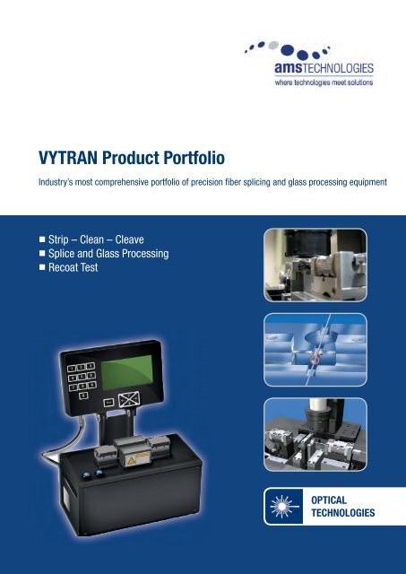
<strong>VYTRAN</strong> <strong>Product</strong> <strong>Portfolio</strong><br />
Industry’s most comprehensive portfolio of precision fi ber splicing and glass processing equipment<br />
• Strip – Clean – Cleave<br />
• Splice and Glass Processing<br />
• Recoat Test<br />
OPTICAL<br />
TECHNOLOGIES
www.amstechnologies.com<br />
CAS-4000 SERIES<br />
One Step Splice<br />
Fire Polish<br />
Low-Loss, High-Strength Splices<br />
High-Volume Manufacturing<br />
True Core Imaging<br />
E-Splice<br />
Compact, Semi-Automated Splicers for Standard<br />
and Specialty Fibers from 80 µm in Diameter<br />
Strip Clean Cleave Splice Recoat Test
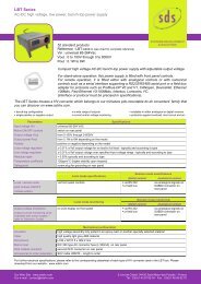
CAS-4000 Series<br />
Compact, Semi-Automated Splicers<br />
The CAS-4000 Series is Vytran’s newest family of splicers. Its individual models are the CAS-4100 and<br />
CAS-4100-P. These compact, semi-automated splicers produce high-strength, consistent splices quickly<br />
and efficiently. CAS systems feature a unique design, advanced imaging capabilities and our One Step<br />
Splice process software with its ultra-simple graphical user interface (GUI). CAS splicers maintain the<br />
full development capabilities of Vytran’s high-precision splicing products, yet have been tailored for highvolume<br />
production, including three-shift manufacturing. CAS-4100-P is designed for use on polarization<br />
maintaining (PM) fibers.<br />
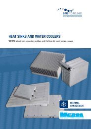
High Performance<br />
At the foundation of<br />
CAS-4000 systems is<br />
our proven filament<br />
fusion technology—the<br />
industry’s most reliable<br />
method for creating highstrength,<br />
low-loss splices.<br />
Probability<br />
www.amstechnologies.com<br />
100%<br />
90%<br />
80%<br />
70%<br />
60%<br />
50%<br />
40%<br />
30%<br />
20%<br />
10%<br />
0%<br />
150 200 250 300 350 400 450 500<br />
Splice Strength (kpsi)<br />
Typically > 200 kpsi (SMF-28 fibers, >96%)<br />
Typically < 0.02 dB (SMF-28, Average 0.01 dB)<br />
Compact and Efficient Design<br />
In both CAS-4100 and CAS-4100-P, all components, including the imaging system, computer and folding<br />
display, are embedded into the splicer to form a single unit ideal for use where space is at a premium.<br />
Ideal for Standard and Specialty Fibers<br />
CAS-4000 systems can be used to splice specialty fibers (doped, PM, ZBLAN, Chalcogenide, PCF) and<br />
fibers with diameters as small as 80 µm. They can also be used for many other applications, such as<br />
manufacturing end caps, thermal core expansion, splicing fiber lenses and more.<br />
Probability<br />
100%<br />
90%<br />
80%<br />
70%<br />
60%<br />
50%<br />
40%<br />
30%<br />
20%<br />
10%<br />
0%<br />
0 0.005 0.01 0.015 0.02 0.025 0.03<br />
Splice Loss (dB)<br />
PCF to SMF-28 Splice<br />
(125/125 µm)<br />
Octagonal Yb-Doped Fiber Cleave<br />
and Splice to HI-1060-FLEX<br />
(125/125 µm)<br />
Grin Lens Splicing<br />
(125/130 µm)<br />
PM-NL 3 µm Hollow Core PCF<br />
to SMF-28 Splice<br />
Square Yb-Doped Fiber Cleave and<br />
Splice to HI-1060-FLEX<br />
(125/135 µm)<br />
Grin Lens Splicing<br />
(125/250 µm)<br />
Key Markets<br />
Fiber-based Fiber Laser Defense Medical Device Sensing Research<br />
Instrumentation and Aerospace and Development
www.amstechnologies.com<br />
CAS-4000 Series<br />
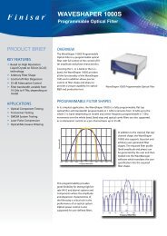
One Step Splice<br />
CAS splicers feature our unique One Step<br />
Splice process software—a system designed<br />
to make splicing simple and user friendly. The<br />
GUI provides two modes of operation:<br />
• In “Operator” mode an ultra-simple screen<br />
features a single splice button that initiates<br />
the splice process.<br />
• In “Development” mode an intuitive<br />
and streamlined screen allows full process<br />
configuration and control.<br />
All splice-related information can be exported<br />
via an Ethernet port for statistical process<br />
control.<br />
End-View Imaging and Splice Loss<br />
Determination<br />
CAS splicers utilize True Core Imaging TM , a<br />
high-resolution imaging system that enables<br />
fast, accurate, inner-core alignment and splice<br />
loss calculation. Vytran has developed a<br />
proprietary algorithm that accurately calculates<br />
loss for splicing a variety of similar or dissimilar<br />
fiber types.<br />
CAS splicers also feature an End-View<br />
Imaging system for looking directly at the<br />
ends of the fibers prior to splicing. This is<br />
used in conjunction with high-resolution rotary<br />
positioners for the automated alignment of PM<br />
fibers through either image-based or active<br />
feedback control. End-View Imaging is also<br />
ideal for working with fiber laser gain fibers,<br />
which may have non-circular claddings or<br />
micro-structured cores.<br />
Patented Fire Polishing<br />
Vytran’s fire polishing process increases splice<br />
strength through a rapid post-fusion heat<br />
treatment of the splice region.<br />
The process:<br />
• removes or minimizes deposits, improving<br />
splice strength.<br />
• provides core diffusion capabilities that can<br />
be used to adiabatically expand the mode<br />
field diameter of a fiber.<br />
• enables low-loss splices between markedly<br />
dissimilar fibers.<br />
One Step Splice Operator Mode<br />
Development Mode<br />
Panda<br />
Tiger<br />
Bow-tie<br />
MM<br />
End Views - Different Fibers<br />
Filament Assembly Travel<br />
Fiber<br />
Filament<br />
Fire Polish
www.amstechnologies.com<br />
CAS-4000 Series<br />
Key Features / Benefits<br />
Unique, semi-automated tools for high-performance, high-volume<br />
splicing; complete with the industry’s simplest user interface<br />
Fully integrated system<br />
Fast, precise positioning + image processing + application software<br />
Fully integrated 6.5˝ x 4.75˝<br />
display<br />
One Step Splice<br />
GUI with two modes<br />
of operation — Operator<br />
and Development<br />
Filament fusion<br />
• Enables low-loss, highstrength<br />
splices<br />
• High polarization<br />
extinction ratio for all<br />
fiber types<br />
True Core Imaging<br />
• Automatic fiber inner core<br />
alignment<br />
• Accurate splice loss<br />
estimation<br />
End-View Imaging<br />
• Accurate alignment<br />
of PM and special<br />
shape fibers<br />
• Facet testing of<br />
cleaved fibers<br />
Fire Polish<br />
• Minimizes deposits and<br />
enhances splice strength<br />
• Furnace travel of up to<br />
+/- 5 mm<br />
Fiber clips<br />
• Accurate, easy to use<br />
and fast<br />
• Compatible with Vytran<br />
PFC-400 cleaver<br />
Ethernet coupled with remote<br />
access for e-service<br />
• Software upload<br />
• Data upload and download<br />
• PC control
Performance CAS-4100 CAS-4100-P<br />
Fiber Types (non-PM)<br />
MM, SM, PCF, LMA, circular, non-circular, silica, soft glass (call factory for your type)<br />
Fiber Types (PM) N/A Panda, Elliptical, Bow-Tie<br />
(call factory for your type)<br />
Fiber Cleave Length Nominally 10 mm - Adjustable from 5 mm to 15 mm (1)<br />
Cladding Diameter Range<br />
80-250 μm<br />
Coating Diameter 100 μm-900 μm (2)<br />
Fusion Method<br />
Filament Temperature Range<br />
Filament Fusion<br />
Room temperature to > 2,500°C<br />
Typical Splice Loss 0.02 dB (for SMF-28) 0.02 dB (for Panda)<br />
Loss Estimation Included Included<br />
Typical Splice Strength (3) >250 kpsi (for SMF-28) >250 kpsi (for Panda)<br />
Strength Enhancement<br />
Yes - Fire Polish included<br />
Polarization Cross-Talk N/A Panda > 35 dB, Others > 30 dB<br />
Splice Return Loss<br />
Tapering<br />
Fiber Side Viewing<br />
>> 50 dB<br />
Available for certain applications (contact factory)<br />
Side View core imaging - True Core Imaging<br />
Fiber End Viewing Optional Included for PM alignment and for<br />
fiber facet inspection<br />
Fiber Alignment Method<br />
Fiber Inspection and Measurement (4)<br />
GUI<br />
Core Diameter<br />
Cladding/Fiber Diameter<br />
End Face Inspection<br />
Cleave Angle<br />
Splice Loss Estimation<br />
Splice Files<br />
Splice Memory<br />
E-Splice (internet ready for volume manufacturing)<br />
Remote Data Access<br />
Remote Control<br />
Remote Inspection<br />
Remote Software Upgrade<br />
Fully automated One Step Splice<br />
Automatic measurement<br />
Automatic measurement<br />
Inspection via display<br />
Automatic measurement<br />
Automatic measurement<br />
One Step Splice in Operator Mode - Process Development Mode with password protection<br />
Built-in library of most common fibers - Very large library available (contact Vytran)<br />
>> than 10,000 Splices<br />
Ethernet<br />
Ethernet using ActiveX control<br />
Ethernet<br />
Ethernet<br />
Monitor Features High resolution full color (1024 x 768)<br />
Size (w/ folded down monitor)<br />
Weight<br />
Power<br />
Gas Supply<br />
www.amstechnologies.com<br />
CAS-4100/4100P Preliminary Performance<br />
295 mm x 270 mm x 270 mm (width, depth, height) including all connectors and screw heads<br />
23 lbs (13 kg)<br />
100 to 240 VAC 50-60 Hz<br />
Ar grade 5.0 or higher (H2O impurities less than 4 ppm and O2 less than 5 ppm)<br />
Operating Temperature 15 to 35°C<br />
(1) Other lengths available - Call factory<br />
(2) Other diameters available - Call factory<br />
(3) Depending on stripping method<br />
(4) All measured data can be exported to database via Ethernet back connector<br />
table continued next page
www.amstechnologies.com<br />
CAS-4100/4100P Preliminary Performance cont.<br />
Performance CAS-4100 CAS-4100-P<br />
Furnace “Z” Movement<br />
Fiber “Z” Movement<br />
Fiber “Z” Resolution<br />
X-Y Fiber Positioning<br />
+/- 3 mm<br />
10 mm<br />
0.2 μm<br />
0.02 μm<br />
Rotation Alignment N/A Fully Automated and Manual<br />
Rotation Drive Resolution N/A 0.02º<br />
Rotation Travel N/A 190º<br />
Key Applications<br />
Splicing<br />
Tapering<br />
Core Diffusion<br />
All fibers above<br />
Available for certain applications (contact factory)<br />
Included<br />
Asymetric Splicing Included (5)<br />
and Heating<br />
GRIN Lenses Included (5)<br />
Segmented Lenses Included (5)<br />
PCF Termination Included (5)<br />
Related <strong>Product</strong>s<br />
Cleaver<br />
Recoater<br />
PFC-400<br />
PTR-200 Series<br />
Accessories (Part #)<br />
Clip-165 (6) - PN: 055005900<br />
125 µm to 210 µm coating size<br />
Clip-250 (6) - PN: 055005910<br />
210 µm to 370 µm coating size<br />
Clip-400 (6) - PN: 055005920<br />
370 µm to 540 µm coating size<br />
Other Sizes<br />
call factory<br />
Filament PN: F35-2520-N12-82-CAS<br />
fiber size 125 µm and under<br />
Filament PN: F35-5020-N22-82-CAS fiber size
LDC-400<br />
LARGE DIAMETER CLEAVER<br />
Precision Cleaver for Standard, Large<br />
Diameter and Specialty Optical Fibers<br />
Strip Clean Cleave Splice Recoat Test
LDC-400<br />
The LDC-400 is a versatile optical fiber<br />
cleaver that can be used to produce precise<br />
and consistent flat and angled cleaves on<br />
fibers ranging from 80 microns to 1.25 mm<br />
(coating up to 3 mm) in diameter. This tensionand-scribe<br />
system combines the well-proven<br />
precision diamond blade scribing technology<br />
used in Vytran’s LDC-200 and LDC-200-G<br />
cleavers and FFS-2000 fusion splicing<br />
workstation with the tensioning capabilities of<br />
our linear proof tester products.<br />
By using the same tension-and-scribe method<br />
that works so well to cleave telecom fibers,<br />
the LDC-400 handles large specialty fibers,<br />
yielding flat, perpendicular cleaves with mirrorquality<br />
end-face finishes.<br />
The cleaver is fully automated with<br />
programmable cleave tension, rotation angle<br />
and scribe conditions, and includes special<br />
processes for cleaving photonic crystal fiber<br />
(PCF), highly stressed fibers, or capillary<br />
tubing. The LDC-400 can also be used to<br />
cleave many non-circular fibers typically<br />
used in fiber laser systems. It uses the same<br />
bottom v-groove inserts as our GPX and LFS<br />
systems, and through the use of a transfer<br />
clamp the cleaved fiber can be conveniently<br />
moved from the cleaver to the GPX/LFS<br />
system. The fact that the registration is<br />
maintained and programmable between the<br />
cleaver and splicer allows for easy fabrication<br />
of end-caps and mode field adaptors. Fiber<br />
inserts must be ordered separately based on<br />
the range of fiber sizes to be used.<br />
Key Markets<br />
Telecommunications • Aerospace and Defense • Fiber Laser • Sensing • Medical • Research<br />
Options<br />
Angle Cleave<br />
The angle cleave option adds a rotary drive<br />
mechanism that can introduce a torsional<br />
component to the pre-scribe tension. This can<br />
be used to produce angle cleaves of up to 15<br />
degrees, a common requirement for reducing<br />
back reflections at a cleaved end-face.<br />
Fiber Holding Block Inserts<br />
A series of individual fiber holding block inserts,<br />
or a full set, can be purchased for fiber sizes<br />
from 80 microns to 1.25 mm.<br />
PCF and Large Diameter cleave<br />
backstop<br />
This option is required to cleave photonic<br />
crystal fibers and very large diameter fibers.<br />
It enables a smoother cleave surface.<br />
1<br />
1<br />
2<br />
3<br />
2<br />
2<br />
3<br />
Fiber Types LDC-400 Basic Configuration Angle Cleave Option Micrometer Backstop Option<br />
SM, PM and MM fibers up to 800 µm<br />
in cladding diameter for flat cleaves<br />
SM, PM, and MM fibers up to 800<br />
µm in cladding diameter for angle<br />
cleaves (up to 15 deg)<br />
•<br />
• •<br />
Recommended for<br />
highly stressed fibers<br />
Recommended for<br />
highly stressed fibers<br />
PCF, PBF,<br />
SM, PM, MM fibers above 800 µm<br />
in cladding diameter, capillary tubes,<br />
non-circular fibers, and specialty devices<br />
(combiners, etc.) for flat cleaves<br />
• •<br />
For other fibers please contact Vytran.
LDC-400<br />
Key Features / Benefits<br />
Internal Vacuum<br />
Ease of fiber loading and<br />
consistent fiber positioning<br />
Adjustable mechanical slide<br />
Enables precise control of cleave position<br />
Angle cleave option<br />
Precise and consistent<br />
angle cleaves<br />
Fiber holding blocks for accurate<br />
fiber positioning and clamping<br />
Results in highest fiber quality<br />
and process repeatability<br />
Tension-and-scribe method<br />
Low-angle and flat cleaves<br />
-- critical for high performance<br />
splicing<br />
Micrometer backstop option<br />
Allows low-tension PCF<br />
cleaves and large diameter<br />
fiber cleaves<br />
Precision controlled<br />
scribing process<br />
Repeatable, consistent and<br />
accurate cleaves<br />
Common fiber holding blocks<br />
with other Vytran tools<br />
For ease of use and maintaining<br />
fiber position<br />
registration during the<br />
cleaving and splicing<br />
processes<br />
Unique “sub-critical”<br />
cleave process<br />
Optimal technique for cleaving<br />
PCF and large diameter fibers<br />
Programmable cleave parameters<br />
Accommodates a wide range of fiber sizes<br />
(80µm to 1.25mm in diameter) and different<br />
types of conventional and specialty fibers,<br />
including circular, PM, non-circular fibers,<br />
PCF and capillary tubes<br />
Remote controlled tension, velocity,<br />
oscillation, scribe delay<br />
Handset controller gives user full control<br />
over the cleave process
Preliminary LDC-400 Specifications<br />
Overall Size<br />
Weight<br />
Power<br />
Ext. Supply<br />
Services<br />
Cleave Method<br />
Scribe<br />
Loading<br />
Rotation (optional)<br />
Max. Tension<br />
Buffer Sizes<br />
Cladding Sizes<br />
Insert sizes<br />
Compliances<br />
H: 5.0˝ (127mm), W: 10.25˝ (260mm), D: 5.0˝ (127mm)<br />
10.0 lbs (4.5 kg)<br />
12.5 VDC, 5A (provided by external power supply)<br />
100-120 / 200-240 VAC, 4.5 / 2.2 A, 47-63 Hz<br />
Internal vacuum pump for fiber holding blocks<br />
Tension and scribe<br />
Diamond blade, stepper motor controlled<br />
Linear tension, stepper motor controlled<br />
0.1 degree resolution, stepper motor controlled<br />
5.5 kg, programmable<br />
160 microns to 3.0 mm<br />
80 microns to 1.25 mm<br />
Individual inserts and full set available for fiber from 80 micron to 1.25 mm<br />
CE - RoHS<br />
Related <strong>Product</strong>s:<br />
GPX–3000 Series<br />
A multipurpose glass processing platform for creating splices, combiners, tapers, couplers and<br />
end-caps with optical fibers from 125 microns to 1.5 mm in diameter.<br />
LFS-4000<br />
A filament fusion splicer for standard, large-diameter and specialty fibers.<br />
www.vytran.com<br />
1400 Campus Drive West | Morganville, NJ 07751 USA<br />
Tel: +1 732-972-2880 Fax: +1 732-972-4410<br />
8 Kew Court Pynes, Hill Office Campus | Rydon Lane | Exeter EX2 5AZ UK<br />
Tel: +44 (0) 1392 445777 | Fax: +44 (0) 1392 445009
LFS-4000<br />
LARGE DIAMETER FIBER SPLICER<br />
Filament Fusion Splicer for Standard, Large<br />
Diameter and Specialty Optical Fibers<br />
Strip Clean Cleave Splice Recoat Test
LFS-4000<br />
A Stand Alone Optical Fiber Splicer<br />
The LFS-4000 combines Vytran’s unique filament fusion technology, a high degree of user process<br />
control, and simple manufacturing operation, making it ideal for volume fiber assembly production. Fully<br />
compatible with our GPX-3400 glass processor, the LFS-4000 inherits the years of development and<br />
library of applications that we have amassed using GPX-3400 systems.<br />
The LFS-4000 splices standard and specialty fibers up to 0.9 mm in diameter. It features the identical<br />
filament “furnace” assembly as the GPX-3400. This stable, high-temperature heat source allows<br />
maximum control of splice processing conditions. An embedded real time control system and powerful<br />
machine level macro programming language allow the user to develop unique event-driven routines<br />
for fast and flexible process development. All high-level system communication is done via a laptop<br />
graphical interface with two complementary screens – one for product development that allows all<br />
system functionalities, and another streamlined screen that allows only basic operator interface for<br />
volume production.<br />
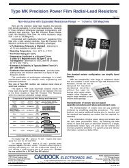
Splicing<br />
Splice standard and specialty<br />
fibers with diameters up to 0.9 mm.<br />
Standard - PM - Doped - PCF<br />
Dissimilar fibers - Off-center fibers<br />
LMA Fibers<br />
Key Applications<br />
Thermal Core Diffusion –<br />
Mode Field Adapters<br />
Thermally diffuse the core dopants<br />
of a fiber, changing its waveguide<br />
characteristics. A controlled heat<br />
distribution profile along the fiber<br />
length enables adiabatic expansion<br />
of the mode field diameter.<br />
Fiber Termination<br />
Terminate all fibers (end caps,<br />
beam delivery fibers, lenses,<br />
etc.)<br />
Splicing Off-centered axis End cap PM fiber Probe Fiber lens<br />
Splicing up to Dissimilar fiber Dissimilar fiber PANDA Ball lens Custom probe<br />
900 µm<br />
Vytran provides application development services. For other applications, please contact us.<br />
Key Markets<br />
Fiber-based Fiber Laser Defense Medical Device Sensing Research<br />
Instrumentation and Aerospace and Development
Filament Fusion Provides Repeatable,<br />
High-Quality Splices<br />
Vytran’s filament fusion technology is a<br />
consistent and reliable method of making<br />
high-strength, low-loss splices. Under purge<br />
of an inert gas, a resistive heating element<br />
supplies the exact amount of thermal energy<br />
necessary for fiber fusion. The heating<br />
element’s size, shape and power delivery<br />
can be changed to suit the application, easily<br />
scaling to very large diameter<br />
fibers.<br />
The filament furnace assembly<br />
can also be moved along the<br />
length of the fiber, making<br />
many specialty processing<br />
applications possible, such as<br />
post-splice fire polishing for<br />
strength enhancement. These<br />
highly controlled conditions,<br />
in combination with constant power control<br />
circuitry, ensure repeatable performance<br />
splice after splice.<br />
LFS-4000<br />
Filament Fusion Technology for Precise and Consistent Splicing<br />
Fire Polishing Enhances Splice<br />
Strength<br />
Vytran’s patented fire polishing process<br />
significantly increases splice strength through<br />
a rapid post-fusion heat treatment of the<br />
splice region. When a fusion splice is made,<br />
silica evaporates off of the hot center region<br />
of the splice and condenses on either side<br />
of the joint where the fiber is cooler. The<br />
condensed silica deposits act as a surface<br />
flaw, lowering splice strength.<br />
Our fire polishing process<br />
removes or minimizes the<br />
deposits, thereby improving<br />
splice strength.<br />
In addition, the fire polishing<br />
process provides core diffusion<br />
capabilities that can be used to<br />
adiabatically expand the mode<br />
field diameter of a fiber. Through<br />
this thermally expanded core (TEC) process,<br />
low-loss fusion splices can be achieved<br />
between markedly dissimilar fibers, such as<br />
those typically used in fiber laser applications.<br />
Key Features<br />
Stable heat source<br />
• Consistent fusion splicing<br />
• Consistent glass processing<br />
• Immune to ambient variation<br />
Benefits<br />
• Various fusion processes, splicing, couplers, end caps, etc.<br />
Wide thermal dynamic range • Accommodates different fiber sizes (125 µm to > 900 µm in diameter)<br />
(a few 100°C to > 2500°C) • Works for different types of fiber materials (silica glass, software glass,<br />
e.g. phosphate glass) that require different treatment temperatures<br />
Wide and uniform concentric heat zone<br />
High fusion power<br />
• Stable and low loss fusion splicing<br />
• Ideal for processing large fiber diameter<br />
Mini fusion environment with Argon assist • “Clean” fiber fusion with negligible surface contamination<br />
Fire polish<br />
Different types of filament designs<br />
Ease of filament replacement<br />
• Low splice loss<br />
• High strength splicing<br />
• High performance mode field adapting<br />
• Provides robustness and flexibility for different applications<br />
• Quick set-up for different applications and fast maintenance
LFS-4000<br />
Complementary <strong>Product</strong> Suite for Development<br />
through Volume <strong>Product</strong>ion<br />
Splice Loss Estimation<br />
The LFS-4000 uses Vytran’s True Core<br />
Imaging technology for precise fiber core<br />
alignment prior to splicing. Because this<br />
technology provides a clear view of the fiber’s<br />
inner core, an accurate estimation of splice<br />
loss can be achieved based on an analysis of<br />
the completed splice. Vytran has developed<br />
a proprietary algorithm that accurately<br />
calculates loss for splicing a variety of similar<br />
or dissimilar single mode fiber types with a<br />
high correlation factor.<br />
End-View Imaging<br />
The LFS-4000 features a unique End-View<br />
Imaging system for looking directly at the<br />
ends of the fibers prior to splicing. This is<br />
used in conjunction with high-resolution<br />
rotary positioners for automated alignment of<br />
polarization maintaining (PM) fibers through<br />
either image-based or active feedback control.<br />
End-View Imaging is also a powerful tool when<br />
working with fiber laser gain fibers, which<br />
may have non-circular claddings or microstructured<br />
cores.<br />
Dual Screen Software Interface<br />
The PC-based laptop software features two<br />
complementary screens. The “development”<br />
screen allows users to access all of the unit’s<br />
functionalities for full process optimization.<br />
The password-protected “production” screen<br />
allows only basic system operator interface for<br />
efficient volume manufacturing.<br />
LFS-4000<br />
LDC-400<br />
GPX-3400<br />
PTR-200<br />
A Complete <strong>Product</strong> Suite<br />
Vytran’s LFS-4000, GPX-3400 glass processor, LDC-400 fiber cleaver, and PTR-200 fiber recoaters<br />
and proof testers make up a suite of complementary products. These tools facilitate early process<br />
development through volume manufacturing for applications such as splicing fiber assemblies and<br />
creating fused components and fiber terminations for fiber lasers, medical devices, sensing and<br />
aerospace, among others.<br />
Our LFS-4000, GPX-3400 and LDC-400 products share a fiber holding block to ensure mechanical fiber<br />
integrity. LFS and GPX systems also share common software and an application library to streamline<br />
processes from development to manufacturing.
LFS-4000<br />
Key Features / Benefits<br />
Filament fusion technology<br />
• High performance splices for fibers<br />
125 µm to 900 µm<br />
• Low-loss, high-strength splices<br />
• Highly stable, consistent, and repeatable<br />
fusion process<br />
• Uniform thermal treatment around<br />
the fiber<br />
• Splice various specialty fibers, includ -<br />
ing PM fibers, non-circular cladding<br />
fibers or micro-structured fibers, and<br />
non-silica soft glass fibers<br />
True Core Imaging (Real-time imaging)<br />
• Accurate splice loss estimation for<br />
SM fibers<br />
• Automatic high-accuracy fiber core<br />
alignment<br />
Fire Polishing<br />
Post-splice fire polishing enhances<br />
splice strength and reduces loss<br />
Other applications<br />
Fabrication of<br />
mode field adapters,<br />
couplers (MM and SM)<br />
and end caps (with<br />
LDC-400 cleaver)<br />
Same fiber holding/transfer<br />
fixtures as GPX 3300/3400<br />
Series and LDC-400 cleaver<br />
Full compatibility with the<br />
GPX 3300/3400 glass<br />
processors<br />
Library of Applications<br />
Shared application<br />
library with established<br />
GPX products<br />
End-View Imaging and<br />
high-resolution rotary<br />
positioners<br />
Automated splicing<br />
alignment for PM<br />
fibers, dissimilar fibers,<br />
off-centered fibers<br />
Dual screen software interface (development<br />
screen; production screen)<br />
• Leverage all system functionalities in develop -<br />
ment mode for full process optimization<br />
• Simplified, locked-in production screen for<br />
automated volume manufacturing process
LFS-4000 Specifications<br />
Size<br />
Weight<br />
Power<br />
Gas Supply<br />
Fusion Method<br />
Fiber Types<br />
Max. Filament Temperature<br />
Max. Fiber Cladding Diameter<br />
Furnace “Z” Movement<br />
Max. Fiber “Z” Movement<br />
9.0″ (W) x 12.5″ (D) x 5.3″ (H) (229 x 318 x 135 mm)<br />
29 lbs (13 kg)<br />
External power supply unit, universal input: 90-260 VAC,<br />
47-63 Hz, single phase<br />
LFS-4000 input: 12V and 48VDC 10A<br />
PC input: 115 or 230 VAC, 47-63 Hz, single phase<br />
Argon, Zero grade at 10 PSIG<br />
Filament<br />
PM, non-PM, PCF, LMA, circular, non-circular, silica, soft glass<br />
~5600ºF (3100ºC)<br />
0.9 mm<br />
16 mm from home position<br />
12 mm<br />
“Z” Movement Resolution 0.2 µm<br />
Alignment Method<br />
Fully Automated and Manual<br />
X-Y Fiber Positioning Resolution 0.02 µm<br />
Fiber Viewing<br />
Strength Enhancement<br />
Loss Estimation<br />
Rotation Alignment<br />
Side View Imaging (core) and End-View Imaging<br />
Fire Polish<br />
Yes<br />
Fully Automated and Manual<br />
Rotation Drive Resolution 0.02º<br />
Rotation Travel 190º<br />
Related <strong>Product</strong>s:<br />
LDC-400<br />
A fully automated precision cleaver for standard, large diameter and specialty optical fibers.<br />
GPX-3400<br />
A multipurpose glass processing platform for creating splices, combiners, tapers, couplers and<br />
end caps with optical fibers from 125 microns to 1.5 mm in diameter.<br />
PTR-200 Series<br />
A family of manual to fully automated fiber recoaters and proof testers for high-volume optical<br />
fiber processing.
PTR-200 SERIES<br />
FIBER RECOATERS AND PROOF TESTERS<br />
A Complete Series of <strong>Product</strong>s for Coating<br />
Restoration and Reliability Testing<br />
Strip Clean Cleave Splice Recoat Test
PTR-200 Series<br />
Vytran is the world’s leading provider of optical fiber recoaters and proof testers. Various product<br />
configurations allow the customer to select among three types of recoat stations - manual, extended<br />
length manual, or automatic - and two types of proof test stations - rotary or linear. These stations can<br />
be ordered individually or in selected recoat/proof test combinations as listed in the Model Configuration<br />
Table.<br />
Protective Coating Restoration and Proof Testing/Tension Testing<br />
Vytran optical fiber recoaters restore the<br />
protective UV acrylate buffer coating to a<br />
stripped or fusion-spliced section of optical<br />
fiber. Because the recoat diameter and recoat<br />
material can be closely matched to the original<br />
fiber, the recoated section of fiber is smooth<br />
and flexible, and can be handled or coiled just<br />
like the original fiber. When used in conjunction<br />
with a proof test qualification, recoating offers<br />
significant packaging and reliability advantages<br />
over standard heat shrink protection sleeves.<br />
Split quartz mold with fiber<br />
All Vytran recoaters use split quartz mold<br />
plates, which, when closed together, form<br />
a circular mold cavity around the exposed<br />
section of fiber. A volumetric dispensing pump<br />
automatically injects a pre-programmed<br />
amount of recoat material into the mold cavity,<br />
which is then cured by exposure to ultraviolet<br />
(UV) light. Special optical coatings on the<br />
surfaces of the mold plates prevent any recoat<br />
material that migrates between the plates from<br />
curing and forming a “flash” on the finished<br />
recoat.<br />
Split quartz mold<br />
Proof Testing<br />
Key Markets<br />
Recoated fiber<br />
Vytran optical fiber proof testers apply a set load at a controlled rate to an optical fiber or fusion splice.<br />
The load can be taken up to a pre-determined level and released - proof test mode - or it can be taken<br />
up to the breaking strength of the fiber - tension test mode. The peak tension is recorded and can be<br />
displayed in units of tension (pounds, kilograms or Newtons) or stress (kpsi or GPa). By selecting a proof<br />
test level approximately three times higher than the applied service load on the fiber or fusion splice, the<br />
long-term reliability of the fiber can be assured.<br />
Optical Fiber Laser Defense Medical Device Sensing Research<br />
Communication and Aerospace and Development
Manual Recoat<br />
The manual recoat mold has a hinged top that<br />
is opened and closed by hand. Recoat material<br />
is injected into the mold cavity via a cross<br />
channel in the mold top plate. The manual<br />
mold is well suited for R&D applications, lowvolume<br />
requirements, or if the mold size or<br />
process must be changed frequently.<br />
PTR-200 Series<br />
Automatic Recoat<br />
The automatic recoat mold uses a pneumatic<br />
gripper assembly to automatically open<br />
and close the mold plates in a front-to-back<br />
direction.This allows direct injection of the<br />
recoat material into the mold cavity without any<br />
excess material to clean after every recoat.<br />
Once the fiber is positioned in the fiber holding<br />
blocks, the entire recoat process is performed<br />
automatically. Continuous, fully automatic<br />
operation makes this an ideal system for highvolume<br />
fiber processing.<br />
PTR-200-MRC<br />
PTR-200-ARL<br />
Proof Testers<br />
The linear optical fiber proof tester is intended<br />
for production proof testing of up to 20<br />
Newtons (235 kpsi for a 125 micron fiber). The<br />
linear proof tester can be combined with either<br />
the manual or automatic recoater. This makes<br />
the linear proof tester well suited for highvolume<br />
production processing.<br />
The rotary optical fiber proof tester/tension<br />
tester features Vytran’s rotating mandrel<br />
design. To proof or tension test a fiber, the<br />
section of fiber to be tested is located between<br />
two mandrels. A load is automatically applied<br />
to the fiber by the rotation of the right-side<br />
mandrel. The rotary proof tester is ideal for<br />
process qualification where high proof test/<br />
tension test levels are required.<br />
PTR-200-RPT
PTR-200 Series<br />
Key Features / Benefits<br />
Manual, automatic, extended-length<br />
recoaters<br />
<strong>Product</strong>s for R&D to high-volume<br />
manufacturing<br />
Smooth, flexible recoats<br />
Enable high packaging density<br />
Pre-programmed volumetric dispensing<br />
• With auto injection<br />
• Ideal for high-volume operation<br />
Linear and rotary proof testers<br />
Choice of products to suit testing needs<br />
Mini controller<br />
Locked-in recipes for simple, repeatable<br />
processes<br />
High-precision fiber holding block<br />
Quartz mold plate<br />
• >10K recoats per<br />
mold<br />
• Durable recoat<br />
finish<br />
Handset control<br />
interface<br />
Easy to use,<br />
intuitive<br />
Unit control buttons for<br />
recoat and proof test<br />
Model Manual Fiber Automatic FIber Automatic Recoat Rotary Proof Linear Proof<br />
Configurations Recoating Recoating Injection Testing Testing<br />
MRC* XLR** MRL* •<br />
MRR*<br />
• •<br />
ARC* ARL*<br />
• • •<br />
RPT<br />
•<br />
LPT<br />
•<br />
*Maximum recoat length is two inches (50 mm)<br />
* *Maximum recoat length is four inches (100 mm)<br />
The standard control interface for all models is via RS-232, allowing easy integration into existing<br />
manufacturing software. Vytran also offers additional control/display interface options, including a minicontroller<br />
display, which provides system status only. The mini-display is a common option for repetitive<br />
production applications where the operator does not need to change process parameters.
General Dimensions<br />
ARC, ARL, LPT, MRC, MRL, RPT, XLR<br />
MRR<br />
Control Panel<br />
External Power Supply<br />
Electrical Requirements<br />
Base Module<br />
Control Panel<br />
External Power Supply<br />
Supply Requirements<br />
ARC<br />
ARC, ARL<br />
Interface<br />
Base Module<br />
Recoating<br />
PTR-200 Series Specifications<br />
H: 5.0˝ (127 mm), W: 10.25˝ (260 mm), D: 5.0˝ (127 mm)<br />
H: 5.0˝ (127 mm), W: 10.25˝ (260 mm), D: 7.0˝ (178 mm)<br />
H: 5.0˝ (127 mm), W: 8.0˝ (203 mm), D: 1.0˝ (25 mm)<br />
H: 2.4˝ (60 mm), W: 4.1˝ (105 mm), D: 12.5˝ (320 mm)<br />
12.5 VDC, 13A (Provided by external power supply)<br />
12.5 VDC, 500 mA (Provided from base module)<br />
Voltage: 100-120 / 200-240 VAC<br />
Current: 4.5 / 2.2A Frequency: 47-63 Hz<br />
Vacuum for fiber holding blocks (external vacuum pump provided)<br />
80-120 psi dry compressed air or gas for pneumatic gripper<br />
RS-232 Serial Communication<br />
Recoating Manual Automatic<br />
Models MRC, XLR, MRR ARC, ARL<br />
Recoat Mold Quartz Quartz<br />
Recoat Diameter<br />
Maximum Recoat Length<br />
Recoat Material<br />
UV Source<br />
260 µm std. for nominal 250 µm fiber. 280 µm std. for nominal 250 µm fiber.<br />
Custom sizes from 200 µm and up. Custom sizes are available.<br />
2˝ (50 mm) for MRC, MRR<br />
2˝ (50 mm) for ARC, ARL<br />
4˝ (100 mm) for XLR<br />
UV Curable Acrylate. DSM 950-200 UV Curable Acrylate. DSM 950-200<br />
recommended.<br />
recommended.<br />
Four 10W halogen lamps for MRC<br />
Eight 10W halogen lamps for XLR<br />
32 UV LEDs<br />
Recoat Injection Automatic, direct from 1 oz. bottle Automatic, direct from 1 oz. bottle<br />
Recoat Volume<br />
Programmable in microliters, 5 µl typical Programmable in microliters, 1.5 µl typical<br />
Recoat Inject Rate Programmable, up to 1.8 µl/s Programmable, up to 1.8 µl/s<br />
Inject/Lamp-on Delay Time Programmable, 5s typical Programmable, 5s typical<br />
Cure Time Programmable, 17s typical Programmable, 17s typical<br />
Mold Cleaning Requirement After every recoat Start-up and shut-down only<br />
Mold Open/Close Method Manual Automatic (pneumatic gripper)<br />
Total Cycle Time 60s typical 45s typical<br />
Proof Testing<br />
Proof Testing Rotary Linear<br />
Modules RPT, MRR LPT, MRL, ARL<br />
Load Application Rotating Mandrel Linear Fiber Clamp<br />
Mandrel Diameter 2˝ (51 mm) N/A<br />
Fiber Clamp Length N/A 1.5˝ (38 mm)<br />
Fiber Spacing 5˝ (127 mm) 2.9˝ (74 mm)<br />
Min. Fiber Length Req. 17˝ (432 mm) 6˝ (150 mm)<br />
Maximum Load<br />
20 lbs, 9.1 kg 4.5 lbs, 2.1 kg<br />
>800 kpsi (5.5 Gpa) for 125 µm fiber 235 kpsi (1.6 Gpa) for 125 µm fiber<br />
Accuracy +/- 2% +/- 2%<br />
Ramp Rate Manual adjust up to 5 lbs/s (2.3 kg/s) Programmable, up to 5 lbs/s (2.3 kg/s)<br />
Hold Time N/A Programmable<br />
Display Units lbs, kg, N, kpsi, GPa lbs, kg, N, kpsi, GPa
PTR-200-PRL<br />
POLYIMIDE RECOATER<br />
High Temperature Recoat Protection<br />
and Linear Proof Testing<br />
Strip Clean Cleave Splice Recoat Test
PTR-200-PRL<br />
The PTR-200-PRL is a stand-alone optical fiber recoating system designed for the application of polyimide<br />
coatings. A “drawing” process applies the polyimide resin which is then thermally cured to form a hard, hightemperature<br />
recoat. A single layer application takes around 60 seconds and results in an approximate thickness<br />
of 3-10 µm per pass, depending on the coating material. Multiple layers can be applied for higher reliability and<br />
increased coating diameters. The resulting recoat has mechanical and thermal properties similar to the original<br />
polyimide-coated fiber.<br />
Fully Automated Process<br />
The section of fiber to be recoated is located between two<br />
fiber holding blocks. Once the recoat process is initiated,<br />
the polyimide resin is automatically pumped to a drawing<br />
head via a volumetric pump. The drawing head, which<br />
consists of dual dies and dual heaters, automatically<br />
makes the user-specified number of “passes” along the<br />
section of fiber. Each “pass” applies a coating of resin,<br />
followed by a low-temperature bake to remove volatiles<br />
and then a high-temperature bake to imidize and harden<br />
the coating. The integral linear proof tester ensures that<br />
proper tension is applied to the fiber during the recoating<br />
process and allows for proof testing of the recoated<br />
section of fiber.<br />
Specifications<br />
Overall Size<br />
H: 5.0″ (127 mm), W: 10.25″ (260 mm), D: 7.0″ (178 mm)<br />
Weight<br />
14.0 lbs (6.4 kg)<br />
Power<br />
48 VDC, 10A (provided by external power supply)<br />
Gas Supply<br />
80-120 psi, dry compressed air or gas supply<br />
Vacuum Supply External vacuum pump provided<br />
Recoating<br />
Recoat Material Thermal cure polyimide<br />
Recoat Dies<br />
Standard size for 125 micron fiber with 155 micron coating (other sizes available)<br />
Recoat Diameter Programmable based on number of layers (approx 3-10 µm per layer, depending on coating material)<br />
Recoat Length 50 mm max<br />
Thermal Source Dual filament heaters<br />
Recoat Injection Automatic direct from 1 oz. bottle<br />
Total Cycle Time 2-7 minutes, depending on number of layers<br />
Proof Testing<br />
Load Application Linear fiber clamp<br />
Clamp Length<br />
1.5″ (38 mm)<br />
Clamp Spacing 3.7″ (94 mm)<br />
Max. Load<br />
4.5 lbs, 2.1 kg, 235 kpsi (1.6 GPa) for 125 micron fiber<br />
Accuracy +/- 2%<br />
Ramp Rate<br />
Programmable, up to 5 lbs/s (2.3 kg/s)<br />
Hold Time<br />
Programmable
WHAT CAN WE DO FOR YOU?<br />
Please contact us for further information<br />
Germany<br />
<strong>AMS</strong> <strong>Technologies</strong> AG<br />
(Headquarters)<br />
Fraunhoferstr. 22<br />
82152 Martinsried<br />
Germany<br />
Phone +49 (0)89 895 77 0<br />
Fax +49 (0)89 895 77 199<br />
info@amstechnologies.com<br />
United Kingdom<br />
<strong>AMS</strong> <strong>Technologies</strong> Ltd.<br />
Unit 11, St Johns Business Park<br />
Lutterworth<br />
Leicestershire LE17 4HB<br />
United Kingdom<br />
Phone: +44 (0)1455 556360<br />
Fax: +44 (0)1455 552974<br />
info@amstechnologies.com<br />
France<br />
<strong>AMS</strong> <strong>Technologies</strong> S.A.R.L.<br />
1, avenue de l’Atlantique<br />
Courtaboeuf<br />
91976 Les Ulis - Courtaboeuf Cedex<br />
France<br />
Phone: +33 (0)1 64 86 46 00<br />
Fax: +33 (0)1 69 07 87 19<br />
info@amstechnologies.com<br />
Italy<br />
Spain<br />
Nordic<br />
<strong>AMS</strong> <strong>Technologies</strong> S.r.l.<br />
<strong>AMS</strong> <strong>Technologies</strong> S.L.<br />
Via San Bernardino, 49<br />
C/Muntaner, 200 Atico, 4a<br />
20025 Legnano (MI)<br />
08036 Barcelona<br />
Italy<br />
Spain<br />
Phone +39 0331 596 693<br />
Phone: +34 93 380 84 20<br />
Fax +39 0331 590 732<br />
Fax: +34 93 380 84 21<br />
info@amstechnologies.com<br />
info@amstechnologies.com<br />
• Optical <strong>Technologies</strong><br />
• Power <strong>Technologies</strong><br />
• Thermal Management<br />
<strong>AMS</strong> <strong>Technologies</strong> Nordic<br />
Azpect Photonics AB<br />
Aminogatan 34<br />
43153 Mölndal<br />
Sweden<br />
Phone +46 (0)8 55 44 24 80<br />
Fax +46 (0)8 55 44 24 99<br />
info@amstechnologies.com<br />
www.amstechnologies.com<br />
© <strong>AMS</strong> <strong>Technologies</strong>. All rights reserved.