SAUC-E IUB Team - Xsens
SAUC-E IUB Team - Xsens
SAUC-E IUB Team - Xsens

Create successful ePaper yourself
Turn your PDF publications into a flip-book with our unique Google optimized e-Paper software.
<strong>SAUC</strong>-E <strong>IUB</strong> <strong>Team</strong><br />
Diana Albu, Andreas Birk, Winai Chonnaparamutt, Petar Dobrev,<br />
Andrei Giurgiu, Sergiu-Cristian Mihut, Bogdan Minzu, Razvan Pascanu,<br />
Sören Schwertfeger, Alexandru Stan, Stefan Videv<br />
International University Bremen, <strong>IUB</strong><br />
Campus Ring 1, 28759 Bremen, Germany<br />
Abstract<br />
The <strong>SAUC</strong>E-E <strong>IUB</strong> team consists mainly of undergraduate and graduate students from<br />
<strong>IUB</strong> which is a private, independent research university founded in February 1999. The<br />
most basic vehicle parts, namely the hull, the batteries, the motors with propellers, and<br />
some sensors were generously provided to <strong>IUB</strong> by Atlas Elektronik. The submarine can<br />
be easily regarded as being composited out of a main hull, a nose and four long tubes.<br />
Those parts house the power system, the propulsion system, the low level controller called<br />
CubeSystem, a high level controller which is a car PC and lots of sensors. The low level<br />
control is based on the so-called CubeSystem.<br />
The submarine uses analog as well as digital sensors. The two sensors that provide<br />
information about the depth of the AUV, namely the pressure sensor and the echo sounder,<br />
are both analog. The submarine has four tubes of nickel-cadmium rechargeable batteries<br />
which are connected in series such that they provide about 29 volt.<br />
The software for the <strong>IUB</strong> AUV comes in two parts. The basic hardware control is done<br />
by the Cube software which is written in C. The AI software is running on the PC which<br />
uses SuSE 10 as operating system. It collects all sensordata from the cube as well as from<br />
the sensors directly attached to it.<br />
1 Introduction<br />
The <strong>IUB</strong> <strong>SAUC</strong>-E team consists mainly of undergraduate students from the <strong>IUB</strong> robotics club<br />
and graduate students from the <strong>IUB</strong> robotics group. The team leader Sören Schwertfeger is a<br />
graduate student in the Smart Systems program. The team is advised by Prof. Dr. Andreas<br />
Birk.<br />
1.1 The International University Bremen (<strong>IUB</strong>)<br />
The International University Bremen (<strong>IUB</strong>) is an innovative, forward-looking concept in the<br />
university landscape of Germany. <strong>IUB</strong> is a private, independent research university founded in<br />
February 1999, which tries to bring many of the best aspects of American higher education to<br />
Germany, including the classic bachelor’s degree, which combines broad exposure to a variety<br />
1
Figure 1: The <strong>IUB</strong> campus.<br />
of intellectual traditions with solid training within a major field of study.<br />
instruction is English.<br />
The language of<br />
<strong>IUB</strong> is a selective, private institution for the advancement of education and research. Students<br />
from over 80 nations are studying at <strong>IUB</strong> for their bachelor’s, master’s, or doctorate degree. This<br />
diversity is also reflected in the <strong>SAUC</strong>-E team. The fields of study and research cover engineering,<br />
the natural sciences, the humanities and the social sciences. The members of the <strong>IUB</strong> robotics<br />
club are predominantly undergraduate students of Electrical Engineering and Computer Science.<br />
The graduates in the team are part of the Smart Systems program in Computer Science. There<br />
are intense robotics research and teaching activities at <strong>IUB</strong>. This includes for example according<br />
courses in the final year of the undergraduate EECS program. Also, the graduate program<br />
Smart System offers a large variety of robotics and AI courses in every semester of the course<br />
plan.<br />
Unlike any other German university, the <strong>IUB</strong> undergraduate studies are based on a residential<br />
college program. There are hence many different social, academic and sports activities on<br />
campus. These activities are organised in clubs that are completely run by the undergraduate<br />
students. The <strong>IUB</strong> robotics club is one of them. It was founded with the start of teaching<br />
and research activities at <strong>IUB</strong> in fall 2001. Members of the club already participated in various<br />
events, especially RoboCup competitions.<br />
1.2 <strong>IUB</strong> Robotics<br />
Robotics research at <strong>IUB</strong> focuses on Autonomous Systems. The expertise of the group ranges<br />
from the development of embedded hardware over mechatronics and sensors to high-level software.<br />
On the basic research side of autonomous systems, machine learning and cooperation<br />
are core themes of robotics research at <strong>IUB</strong>. The systems developed at <strong>IUB</strong> are used in various<br />
domains especially rescue robots [BC06].<br />
Rescue robots can be highly valuable tools in urban rescue missions after severe disasters like<br />
earthquakes, bomb- or gas-explosions. The robots can be used to inspect collapsed buildings,<br />
to assess the situation and to search and locate victims. There are many engineering and<br />
scientific challenges in this domain. Rescue robots not only have to be designed for the harsh<br />
environmental conditions of disasters, but they also need advanced capabilities like intelligent<br />
2
Figure 2: Two <strong>IUB</strong> rescue robots in a test arena in the robotics lab (left) and an <strong>IUB</strong> robot<br />
participating in a disaster drill involving hazardous materials (right).<br />
Figure 3: The expertise at <strong>IUB</strong> robotics covers autonomous systems from various domains. Work<br />
in the past includes behaviour oriented robots (left), a humanoid torso (center) and soccer robots<br />
(right). The autonomous underwater vehicle for <strong>SAUC</strong>-E is hence to some extent a completely<br />
new endeavour, though we expect that a lot of our general experience with autonomy can be<br />
also used in this field.<br />
behaviours to free them from constant supervision by operators. Since 2001 the International<br />
University Bremen (<strong>IUB</strong>) is actively engaged in this research field [BCC + 06] [Bir05] [BCK04]<br />
[BKR + 02].<br />
The <strong>IUB</strong> Rescue Robots are complete in-house developments based on the so-called CubeSystem,<br />
a collection of hardware and software components for fast robot prototyping. The development<br />
of intelligent behaviours is in addition to the robots’ mechatronics a great challenge in this<br />
research area. The robot must for example autonomously detect victims and hazards. Special<br />
sensors like CO2 detectors and Infrared cameras can be helpful to detect humans, but they<br />
nevertheless require advanced techniques to enable even the most basic machine intelligence.<br />
This holds not only in respect to perception, but even more in respect to world modelling, e.g.,<br />
in the form of learning of environment’s maps. Hence recent projects of <strong>IUB</strong> robotics include<br />
the machine learning of the perception of humans in unstructured environments as well as the<br />
learning of 3-dimensional models of according environments.<br />
In addition to rescue robotics, <strong>IUB</strong> robotics has the expertise of developing robots for various<br />
domains ranging from educational activities [ADB + 00, BGK00] over basic research [BW02,<br />
BKS02] to industrial applications [BK02, BK01]. The underwater domain is a novel field for<br />
3
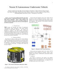
Figure 4: Some of the most basic vehicle parts, namely the hull, the motors and the batteries,<br />
are based on parts from a so-called Seafox ROV that was provided by ATLAS ELEKTRONIK<br />
to <strong>IUB</strong>. The complete development of the electronics, the sensors, the onboard computer, the<br />
actuators, and software was solely done by the <strong>IUB</strong> team.<br />
us, but we see the very interesting scientific challenges especially with regard to autonomy<br />
in this field [Yon92]. Underwater exploration is of tremendous interest from the industrial as<br />
well as from the scientific perspective, let it be in shallow coastal waters or in the deep sea.<br />
Examples include the exploration of seismic and volcanic activities [UOTG01], environmental<br />
monitoring [UAP97, Cra86], archaeological research [CNB00] and of course the exploration of<br />
natural resources [NYMM76].<br />
2 The AUV Hardware<br />
2.1 Core Vehicle Parts<br />
The most basic vehicle parts, namely the hull, the batteries, the motors with propellers, and<br />
some sensors were generously provided to <strong>IUB</strong> by the Bremen company ATLAS ELEKTRONIK.<br />
4
The parts belong to a so-called SeaFox ROV which is used as a mine identification and disposal 1<br />
system. It is designed to be remotely controlled over an expendable fibre optic cable and to dive<br />
to a depth of up to 300 meters. The SEAFOX system is already in-service with the German Navy<br />
since 1998 and under contract with the Royal Swedish, the Royal Netherlands, the Belgian, and<br />
the US Navies. The vehicle itself is small (length 1.3 m) and light (weight approx. 43 kg). The<br />
maximum forward speed is six knots forward, which is of course not used during the competition,<br />
and less than one knot reverse.<br />
The main reason for using these parts is simply cost as the project was solely started as a student<br />
project. The goal is to make a first step to explore the possibilities to carry over results from<br />
the autonomous land-based <strong>IUB</strong> robots to the underwater domain. The <strong>SAUC</strong>-E competition<br />
is a very good testbed for this purpose.<br />
Though these core parts are in principle very nice, their main disadvantage is that they are laid<br />
out for a vehicle which is designed to cover longer ranges. It is hence fast but not extremely<br />
maneuverable, which gives a certain disadvantage for the tasks asked for at <strong>SAUC</strong>-E. As mentioned,<br />
budgetary constraints did not allow for any alternative solutions that are quite easy to<br />
conceive.<br />
Picture 4 shows the hull and the motors with propellers.<br />
2.2 Part List<br />
The submarine can be easily regarded as being composited out of a main hull, a nose and four<br />
long tubes. Those parts house the power system, the propulsion system, the low level controller<br />
called CubeSystem, a high level controller which is a car PC and lots of sensors.<br />
The nose section contains:<br />
• Pressure sensor for depth measurement<br />
• Heading sensor including pitch and roll sensor<br />
• High-resolution sonar head<br />
• Front camera<br />
The middle section contains:<br />
• Echo Sounder<br />
• Vertical thruster mounted in an open ended cylinder perpendicular to the vehicle body<br />
• Cube System<br />
• PC<br />
• PSU for Cube, PC and sensors<br />
1 Unfortunately the explosives used to destroy the mines have been removed before the vehicle was handed out<br />
to the <strong>IUB</strong> team ...<br />
5
Figure 5: The disassembled vehicle. The old unused electronics is left of the vehicle. The<br />
sonar board which is used to control the seeking sonar is below the thrusters. The nose of the<br />
submarine with the sonar and the pressure sensor as well as one of the batteries is on top of<br />
the vehicle. Right of the sub is the new power supply, the orange gyro and a cube system. A<br />
first testversion of a Cube base-board is next to the car computer and in front of the two USB<br />
cameras. The back of the submarine with the four fins is also shown.<br />
Outside, below the middle section the following is attached to the vehicle:<br />
• USB camera<br />
• Marker disposal system<br />
Four battery tubes are attached to the middle section, each containing:<br />
• Propulsion motor<br />
• Propeller with guards<br />
• Electronics for motor control<br />
• Battery<br />
The submarine is trimmed slightly positively buoyant, i.e. it comes up to the surface in case<br />
of some error. Thus the middle thruster has to be used to force the vehicle under water. The<br />
maximum power of the four propulsion motors is 350 W of which up to 280 W are usable due<br />
6
to PWM duty cycle limitations. The 3-blade propellers are protected by guards for safety while<br />
handling and also for preventing the fibre optical cable to be cut.<br />
2.3 Low level controller<br />
The low level control is based on the so-called CubeSystem. It is a collection of hardware- and<br />
software-components for fast robot prototyping developed in the <strong>IUB</strong> lab. It is also used in the<br />
EECS education at <strong>IUB</strong>. The main goal of the CubeSystem project is to provide an open source<br />
collection of generic building blocks that can be freely combined into an application.<br />
The most basic parts of the CubeSystem are<br />
• RoboCube: a special embedded controller, or more precisely controller family, based on the<br />
MC68332 processor<br />
• CubeOS: an operating system, or more precisely an OS family<br />
• RobLib: a library with common functions for robotics<br />
86mm<br />
40mm<br />
CPU + MEM<br />
Ext Busmaster<br />
I/O extension<br />
Figure 6: The structure of a CubeSystem application (left). A RoboCube processor-, bus- and<br />
I/O-board stacked together (center), leading to a compact controller hardware (right).<br />
The general CubeOS and RobLib are collections of software components that can be customised<br />
and combined to a particular set of libraries suited for a particular application. The CubeOS<br />
has for example POSIX constructs to write realtime code. The RobLib provides for example<br />
generic functions for controlling motors via Pulse-Width-Modulation (PWM). The CubeSystem<br />
also allows quite some flexibility to adopt the hardware side to the actual application. The<br />
RoboCube or short Cube features some standard electronic components like the processor-, bus-<br />
, and I/O-board that are combined with a more application specific base-board. The boards<br />
are equipped with a special stacking connector that allows to put several boards on top of each<br />
other. The compact form factor of the boards and the stacking leads to a cubic shape of the<br />
controller (figure 6), hence the name RoboCube. The organisation of the Cube architecture can<br />
be thought of in a tree-like manner. At the root is the minimal Cube, namely a processor-board<br />
which can be expanded by a bus-board. This new branch adds new functionalities like, e.g.,<br />
UARTs and I 2 C controllers that allow to expand to further branches, for example in form of<br />
certain sensors.<br />
So, a CubeSystem application is a concrete instance of a collection of components, for example<br />
in form of a mobile soccer robot. The task for the <strong>IUB</strong> AUV team was hence to design a suited<br />
77mm<br />
7
Figure 7: The CubeSystem programs for the AUV are developed and compiled on a compilehost,<br />
i.e., a Linux server where the proper cross-compiler and the libraries are installed. The<br />
binaries are downloaded via an access-host, typically an arbitrary PC, to the robot.<br />
baseboard and low level software based on RobLib functions. The particular challenge is the<br />
number of motors, namely five, in contrast to the usual number of two on land-based robots.<br />
Furthermore, locomotion is harder as it is in 6D.<br />
Figure 8: The schematics for a first version of a Cube base board for the <strong>IUB</strong> AUV.<br />
The <strong>IUB</strong> AUV is just like any mobile robot a typical embedded system with an according<br />
development environment. The structure of the development environment is shown in figure<br />
7. The CubeSystem is connected via a serial connection to the so-called access-host. This<br />
connection is a simple RS-232 cable. The AUV CubeSystem is programmed for efficiency reasons<br />
only in C. The generation of executables, i.e., compilation and linking, is done on a so-called<br />
compile-host. In doing so, the GNU tool chain with an according cross-compiler is used. The<br />
generic CubeOS and Roblib, as well as customised and pre-compiled instances, are also located<br />
on the compile-host.<br />
2.4 High level controller<br />
The RoboCube with its MC68332 micro-controller is not suited for any high-level computation<br />
that are required for fully autonomous control of an underwater vehicle. Like in many other <strong>IUB</strong><br />
robots an additional PC is used as a so-called compute host, which is also dubbed “cognition”<br />
unit. For the <strong>IUB</strong> AUV, a Sumicom S625F car-computer is used as compute host (figure 10).<br />
This PC is a fanless computer with a Celeron M 370 at 1.5 GHz. It supports a standard 2.5”<br />
hard disk, runs on 12V, weighs about 1.5 kg, and it is very compact, namely 14.6 x 25 x 4.2 cm.<br />
It has a fair collection of interfaces, namely<br />
8
Figure 9: The computation requirements for a fully autonomous underwater vehicle go far<br />
beyond what the CubeSystem can do. Like on other <strong>IUB</strong> robots, a PC running Linux is used<br />
on the AUV as a “cognition” unit.<br />
• front panel<br />
– 1 x IEEE 1394 Firewire port<br />
– 1 x USB 2.0 / 1.1 Port<br />
– 1 x MIC Port<br />
– 1 x Ear Phone output Jack<br />
• back panel<br />
– 1 x RS-232 COM port<br />
– 1 x parallel printer port<br />
– 1 x RJ45 10/100Mb Fast Ethernet<br />
– 1 x Line-Out output Jack<br />
– 2 x USB 2.0 / 1.1 Ports<br />
– 1 x 15 pin VGA<br />
– 1 x 12v DC Power Jack input<br />
For saving energy the optical drive, which is not needed under water, has been removed from<br />
the Sumicom computer. To be able to do some realtime debugging a fibre optic cable connects<br />
the PC inside the sub with a land based operator station. It provides a normal IP connection<br />
using of the shelf parts.<br />
2.5 Sensors<br />
The submarine uses analog as well as digital sensors. The analog sensors are connected to the<br />
Cube System which already provides several A/D converters. The two sensors that provide<br />
information about the depth of the AUV, namely the pressure sensor and the echo sounder, are<br />
9
Figure 10: The Sumicom S625F as “cognition” unit on the <strong>IUB</strong> AUV.<br />
both analog. The digital sensors are all connected via serial lines to the PC. The sonar head<br />
and the heading sensor use RS-232 while the two cameras are connected via USB.<br />
The two RS-232 sensors are connected using USB to serial converters since the only RS-232<br />
connector of the PC is used for the communication between the Cube and the PC. Since there<br />
are four devices to connect to the PC which only has three USB ports, the use of a USB hub is<br />
needed.<br />
2.5.1 Heading Sensor<br />
In the submarine the heading sensor named MTi from the company <strong>Xsens</strong> is used. This is<br />
a complete miniature inertial measurement unit with an integrated 3D compass. It has an<br />
embedded processor capable of calculating the roll, pitch and yaw in real time, as well as<br />
outputting calibrated 3D linear acceleration, rate of turn (gyro) and (earth) magnetic field data.<br />
The MTi uses a right handed Cartesian co-ordinate system which is body-fixed to the device<br />
and defined as the sensor co-ordinate system. Since the gyro is placed near the center of the<br />
sub the orientations provided by the device can directly be used as vehicle orientations.<br />
The heading sensor is used to measure and control the roll, pitch and yaw of the AUV.<br />
ϕ = roll 2 = rotation around X, defined from [−180...180]<br />
θ = pitch 3 = rotation around Y, defined from [−90...90]<br />
ψ = yaw 4 = rotation around Z, defined from [−180...180]<br />
2 roll is also known as: bank<br />
3 pitch is also known as: elevation or tilt<br />
4 yaw is also known as: heading, pan or azimuth<br />
10
2.5.2 Seeking Sonar<br />
The submarine has a seeking sonar which enables it to scan the surrounding for obstacles and<br />
their distance by emmiting soundsignals of 550 kHz and measuring the time it takes until the<br />
sounds echo comes back. The sonar covers up to 360 degrees since it is being turned by a<br />
motor in steps of one degree or bigger and it has a resolution of 1.5 ◦ . The range of the sonar is<br />
selectable to up to 80 meters. The sensor can also scan vertically with a coverage of ± 20 ◦ . The<br />
horizontal scan rate is about 60 ◦ per second at distances of up to 10 m.<br />
The electronics needed to control the sonar and its motors is located on an extra board. This is<br />
the only electronics componend that was reused from the original Atlas SeaFox. It is connected<br />
to the PC via RS-232 and a USB to serial converter.<br />
Figure 11: The nose of the submarine with the seeking sonar (the black cylinder underneath).<br />
The sonar board and the cables leading to it are also visible. The metal stick coming out of the<br />
top of the nose it the pressure sensor.<br />
2.5.3 Pressure sensor<br />
The pressure sensor measures the depth of the submarine below the water surface. It has an<br />
operating pressure range from 0 to 31 bar and a resolution of ± 10 millibar.<br />
2.5.4 Echo sounder<br />
The echo sounder measures the distance from the submarine to the ground by emmiting sound<br />
pulses with a frequency of 500 kHz and a width of 100 µs. The echo of this sound signal is being<br />
received and the travel time measured is then used to calculate the depth. The beam width is<br />
± 3 ◦ , the accuracy ± 5 cm and the depth range 0.5 to 9.8 meters.<br />
2.5.5 USB cameras<br />
Two Creative NX Ultra USB cameras are used in the vehicle. They support a resolution of up<br />
to 640 x 480 pixel. Those USB 1.1 devices have a wide-angle lens which enables a field of view<br />
11
Figure 12: The left picture shows the middle section of the AUV from below. The middle<br />
thruster that forces the submarine downwards can be seen next to the yellow echo sounder. The<br />
orange heading sensor as well as the two USB cameras are shown in the right image.<br />
of 78 ◦ . The camera at the bottom of the submarine is used to locate the circular bottom target<br />
and guide the submarine directly over it such that the markers can be released precicely. The<br />
front camera is used to search for the bottom as well as the mid-water target.<br />
2.6 Power<br />
The submarine has four tubes of nickel-cadmium rechargeable batteries. The six cells of a battery<br />
have a combined voltage of 7.2 volt and, when fully charged, 7 ampere hours. The batteries are<br />
connected in serial such that they provide about 29 volt. Fully charged batteries supply power<br />
for more than two hours of operation time. The <strong>IUB</strong> team uses twelve of those batteries such<br />
that discharged batteries can be recharged outside of the sub. The batteries are charged with<br />
the Charge Terminal Plus from Conrad Electronic. With those devices the charging of an empty<br />
battery takes about two hours.<br />
Each end of the battery pipes is therefore easily sealable with metal catch. The upper seals<br />
contain a flashlight and an analog black and white camera which is not used by the <strong>IUB</strong> team<br />
while the lower ones are solid metal. A small industrial power supply is used to provide 12V and<br />
5V which are needed for the PC, the Cube and the sensors. The ICP Electronics Inc. supply<br />
has an input range from 18V to 36V direct current and supports up to 10A on the 5V and up<br />
to 2.5A on the 12V line.<br />
An external switch is used to cut off the power of the Cube system which immediately stops all<br />
motors since the relays are opened and now PWM is being generated.<br />
2.7 Marker disposal system<br />
The markers are designed to be very lightweight to ensure a stable position of the sub after the<br />
dropping of the marker. To have the least number of modifications to the hull it was decided to<br />
use a magnetic system to release the markers. The markers are made out of permanent magnets<br />
which can be pushed away from the vehicle using electromagnets once the submarine is over the<br />
target.<br />
12
Figure 13: The left image shows some of the batteries together with the four seals. One of the<br />
chargers and the power supply unit for the submarine are on display in the right picture.<br />
3 The AUV Software<br />
The software for the <strong>IUB</strong> AUV comes in two parts. The basic hardware control is done by the<br />
Cube software which is written in C. It uses the CubeOS and the RobLib to generate the proper<br />
PWM signals, to decode the encoder signals from the motors and to access the analog pressure<br />
and echo sound sensors. The software running on the cube is also responsable for maintaining<br />
a certain depth which is set by the actual AI software.<br />
The AI software is running on the PC which uses SuSE 10 as operating system. It collects all<br />
sensordata from the cube (depth and speed) as well as from the sensors directly attached to it.<br />
It uses the high-resolution sonar head to localise itself and the other objects in the basin. The<br />
front USB camera is also used to find objects while the sole purpose of the downlooking camera<br />
is to locate the target situated on the bottom of the tank. The software rescues some functions<br />
and libraries developed for other <strong>IUB</strong> Robotics projects and is written in C++. The Cube and<br />
the PC communicate over the RS-232 line using a special ASCII protocoll.<br />
In order to successfully complete the mission the AUV runs an finite state automaton which<br />
defines which tasks should be solved next. For each task the same three important steps are<br />
accomplished. First the robot has to localise itself in the pool. Secondly the location of the<br />
targets with respect to the global co-ordinate system have to be determined. Lastly the AI<br />
software has to determine the actions that should take place next.<br />
3.1 Self-localisation<br />
The position of the submarine is computed using the seeking sonar, returning a distance to the<br />
nearest obstacle in a specified direction. Using the points determined in this way, the Hough<br />
Transform is applied, in order to find out the edges of the environment [DH72]. The distances to<br />
the walls of the environment determine the absolute position of the submarine in the horizontal<br />
plane. On the vertical axis, the position is determined using the pressure sensor and the vertical<br />
sonar, while the orientation of the submarine is determined with a heading sensor.<br />
13
3.2 Target localisation<br />
For the target location the front and bottom camera as well as the seeking sonar located in the<br />
head of the submarine are used. However, the sonar is somewhat slow, needing up to 6 seconds<br />
to give a new 360 degree view of the surroundings. This is why the cameras are the devices that<br />
the sub mostly relies on. They provide real-time information that is used to create a virtual<br />
map where the target is identified and pursued. Also based on this information the sub takes<br />
corrective measures to ensure the completion of the given task (going through the frame, finding<br />
the optimum place from where to release the markers, etc).<br />
3.3 AI software<br />
After acknowledging the position of itself and of the targets inside pool, this information is<br />
processed in order to obtain the next step. The AI behind the robot consists different operational<br />
states that correspond to different stages of the competition. According to the state the AI is<br />
and the input information a decision is taken. Also the AI comes with a self evaluation function<br />
that is used to determined if the stage of the competition is completed, only after this function<br />
evaluates to true the AI goes into the next state. Each ”state” of the AI is developed as a<br />
separate stand alone module (since everything including the evaluation function is competition<br />
stage dependent) and then the robot is just forced to go through each module in a determinate<br />
order. Each stage is created using a feedback model, meaning that according to the input<br />
information does the most probable action and afterwards re-evaluates the situation. Since the<br />
information from the sensors is not extremely accurate the evaluation functions uses fuzzy logic<br />
to determine what needs to be done. A basic obstacle avoidance behaviour is also implemented<br />
to prevent the AUV from unintentionally hitting midwater objects [Ark20].<br />
A proportional-integral-derivative controller (PID controller) is used to determine the PWM that<br />
is to be put to the middle thruster [AH95]. This way a stable depth can be accomplished even<br />
under difficult circumstances. The controller compares the measured values from the pressure<br />
and the echo sound sensor and calculates the difference of this values with a reference setpoint<br />
value.<br />
References<br />
[Ark20]<br />
[ADB + 00]<br />
[AH95]<br />
[BC06]<br />
C. Arkin Behavior-based robotics. In Intel ligent Robots and Au- tonomous Agents<br />
In Cambridge, MIT Press, 2000 TY - CONF.<br />
Minoru Asada, Raffaello D’Andrea, Andreas Birk, Hiroaki Kitano, and Manuela<br />
Veloso. Robotics in edutainment. In Proceedings of the International Conference<br />
on Robotics and Automation, ICRA’2000. 2000.<br />
K.J. ASTROM, and T. HAGGLUND. PID controllers: theory, design and tuning<br />
In Instrument Soclety of America, 1995 TY - CONF.<br />
Andreas Birk and Stefano Carpin. Rescue robotics - a crucial milestone on the road<br />
to autonomous systems. Advanced Robotics Journal, 20(5), 2006.<br />
14
[BCC + 06]<br />
[BCK04]<br />
[BGK00]<br />
[Bir05]<br />
Andreas Birk, Stefano Carpin, Winai Chonnaparamutt, Viktoras Jucikas, Hamed<br />
Bastani, Ivan Delchev, Ivan Krivulev, Seongchu Lee, Stefan Markov, and Andreas<br />
Pfeil. The <strong>IUB</strong> 2005 rescue robot team. In Itsuki Noda, Adam Jacoff, Ansgar<br />
Bredenfeld, and Yasutake Takahashi, editors, RoboCup 2005: Robot Soccer World<br />
Cup IX, Lecture Notes in Artificial Intelligence (LNAI). Springer, 2006.<br />
Andreas Birk, Stefano Carpin, and Holger Kenn. The <strong>IUB</strong> 2003 rescue robot team.<br />
In D. Polani, B. Browning, A. Bonarini, and K. Yoshida, editors, RoboCup 2003:<br />
Robot Soccer World Cup VII, volume 3020 of Lecture Notes in Artificial Intelligence<br />
(LNAI). Springer, 2004.<br />
Andreas Birk, Wolfgang Günther, and Holger Kenn. Development of an advanced<br />
robotics-kit for education and entertainment of non-experts. In 1st International<br />
Workshop on Edutainment Robotics. 2000.<br />
Andreas Birk. The <strong>IUB</strong> 2004 rescue robot team. In Daniele Nardi, Martin Riedmiller,<br />
and Claude Sammut, editors, RoboCup 2004: Robot Soccer World Cup VIII,<br />
volume 3276 of Lecture Notes in Artificial Intelligence (LNAI). Springer, 2005.<br />
[BK01] Andreas Birk and Holger Kenn. An industrial application of behavior-oriented<br />
robotics. In Proceedings of the International Conference on Robotics and Automation,<br />
ICRA’2001. IEEE Press, 2001.<br />
[BK02]<br />
[BKR + 02]<br />
[BKS02]<br />
Andreas Birk and Holger Kenn. Roboguard, a teleoperated mobile security robot.<br />
Control Engineering Practice, 10(11):1259–1264, 2002.<br />
Andreas Birk, Holger Kenn, Martijn Rooker, Agrawal Akhil, Balan Horia Vlad,<br />
Burger Nina, Burger-Scheidlin Christoph, Devanathan Vinod, Erhan Dumitru,<br />
Hepes Ioan, Jain Aakash, Jain Premvir, Liebald Benjamin, and Luksys Ge. The<br />
<strong>IUB</strong> 2002 rescue robot team. In Gal Kaminka, Pedro U. Lima, and Raul Rojas,<br />
editors, RoboCup-02: Robot Soccer World Cup VI, LNAI. Springer, 2002.<br />
Andreas Birk, Holger Kenn, and Luc Steels. Programming with behavior processes.<br />
International Journal of Robotics and Autonomous Systems, 39:115–127, 2002.<br />
[BW02] Andreas Birk and Julie Wiernik. An n-players prisoner’s dilemma in a robotic<br />
ecosystem. International Journal of Robotics and Autonomous Systems, 39:223–<br />
233, 2002.<br />
[CNB00] D.F. Coleman, J.B. Newman, and R.D. Ballard. Design and implementation of<br />
advanced underwater imaging systems for deep sea marine archaeological surveys.<br />
In OCEANS 2000 MTS/IEEE Conference and Exhibition, volume 1, pages 661–665<br />
vol.1, 2000. TY - CONF.<br />
[Cra86] W. Craik. Monitoring in the great barrier reef marine park. In OCEANS, volume 18,<br />
pages 785–790, 1986. TY - CONF.<br />
[DH72]<br />
R.O. Duda, and P.E Hart Use of the Hough transform to detect lines and curves in<br />
pictures In CACM, March 1972 TY - CONF.<br />
15
[NYMM76] E. Nebrija, C. Young, R. Meyer, and J. Moore. Electrical prospecting methods<br />
applied to shallow-water mineral exploration. In OCEANS, volume 8, pages 56–66,<br />
1976. TY - CONF.<br />
[UAP97]<br />
[UOTG01]<br />
[Yon92]<br />
M. Uliana, F. Andreucci, and B. Papalia. The navigation system of an autonomous<br />
underwater vehicle for antarctic exploration. In OCEANS ’97. MTS/IEEE Conference<br />
Proceedings, volume 1, pages 403–408 vol.1, 1997. TY - CONF.<br />
T. Ura, T. Obara, S. Takagawa, and T. Gamo. Exploration of teisi knoll by autonomous<br />
underwater vehicle ”r-one robot”. In OCEANS, 2001. MTS/IEEE Conference<br />
and Exhibition, volume 1, pages 456–461 vol.1, 2001. TY - CONF.<br />
L. Yongkuan. Auv’s trends over the world in the future decade. In Autonomous Underwater<br />
Vehicle Technology, 1992. AUV ’92., Proceedings of the 1992 Symposium<br />
on, pages 116–127, 1992. TY - CONF.<br />
16