750-303 - Binar Elektronik
750-303 - Binar Elektronik
750-303 - Binar Elektronik

You also want an ePaper? Increase the reach of your titles
YUMPU automatically turns print PDFs into web optimized ePapers that Google loves.
0123456789<br />
0123456789<br />
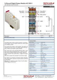
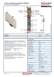
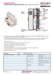
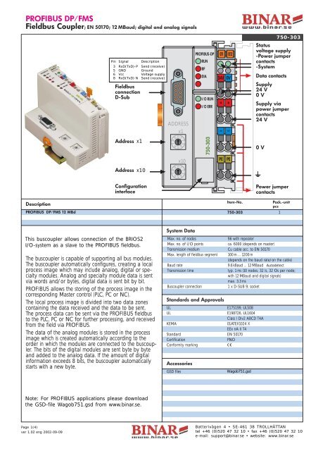
PROFIBUS DP/FMS<br />
Fieldbus Coupler; EN 50170; 12 MBaud; digital and analog signals<br />
<strong>750</strong>-<strong>303</strong><br />
Pin Signal Description<br />
3 RxD(TxD)-P Send (receive)<br />
5 GND Ground<br />
6 Vcc Voltage supply<br />
8 RxD(TxD) N Send (receive)<br />
Fieldbus<br />
connection<br />
D-Sub<br />
ADDRESS<br />
x1<br />
PROFIBUS-DP<br />
RUN<br />
BF<br />
DIA<br />
I/O RUN<br />
I/O ERR<br />
A<br />
B<br />
01 02<br />
C<br />
D<br />
24V 0V<br />
+ +<br />
— —<br />
Status<br />
voltage supply<br />
-Power jumper<br />
contacts<br />
-System<br />
Data contacts<br />
Supply<br />
24 V<br />
0 V<br />
Supply via<br />
power jumper<br />
contacts<br />
24 V<br />
Address<br />
x1<br />
<strong>750</strong>-<strong>303</strong><br />
0 V<br />
x10<br />
PE<br />
PE<br />
Address<br />
x10<br />
Configuration<br />
interface<br />
Power jumper<br />
contacts<br />
Description<br />
PROFIBUS DP/FMS 12 MBd<br />
Item-No.<br />
<strong>750</strong>-<strong>303</strong> 1<br />
Pack.-unit<br />
pcs<br />
This buscoupler allows connection of the of the BRIOS2<br />
I/O-system WAGO ➟I/O➟SYSTEM as a slave to as the a slave PROFIBUS to the PROFIBUS fieldbus. fieldbus.<br />
The buscoupler is capable of supporting all bus modules.<br />
The buscoupler automatically configures, creating a local<br />
process image which may include analog, digital or specialty<br />
modules. Analog and specialty module data is sent<br />
via words and/or bytes, digital data is sent bit by bit.<br />
PROFIBUS allows the storing of the process image in the<br />
corresponding Master control (PLC, PC or NC).<br />
The local process image is divided into two data zones<br />
containing the data received and the data to be sent.<br />
The process data can be sent via the PROFIBUS fieldbus<br />
to the PLC, PC or NC for further processing, and received<br />
from the field via PROFIBUS.<br />
The data of the analog modules is stored in the process<br />
image which is created automatically according to the<br />
order in which the modules are connected to the buscoupler.<br />
The bits of the digital modules are sent byte by byte<br />
and added to the analog data. If the amount of digital<br />
information exceeds 8 bits, the buscoupler automatically<br />
starts with a new byte.<br />
When implementing new installations with<br />
PROFIBUS DP, please consider fieldbus coupler<br />
<strong>750</strong>-333 with extended functions (page 1.016).<br />
Note: For PROFIBUS applications please also order<br />
Note: For PROFIBUS applications please download<br />
GSD files.<br />
the<br />
Item-No.<br />
GSD-file<br />
<strong>750</strong>-910.<br />
Wagob751.gsd from www.binar.se.<br />
or<br />
download it from: www.wago.com<br />
Page Subject 1(4) to design changes<br />
ver 08.10.2001 1.02 eng 2002-09-09<br />
System Data<br />
Max. no. of nodes<br />
96 with repeater<br />
Max. no. of I/O points<br />
ca. 6000 (depends on master)<br />
Transmission medium Cu cable acc. to EN 50170<br />
Max. length of fieldbus segment 100 m ... 1200 m<br />
(depends on the baud rate/on the cable)<br />
Baud rate<br />
9.6 kBaud ... 12 MBaud Autodetect<br />
Transmission time<br />
typ. 1 ms (10 nodes; 32 Is, 32 Os per node;<br />
with 12 MBaud and digital signals)<br />
max. 3.3 ms<br />
Buscoupler connection<br />
1 x D-SUB 9; socket<br />
Standards and Approvals<br />
UL<br />
E175199, UL508<br />
UL<br />
E198726, UL1604<br />
Class I Div2 ABCD T4A<br />
KEMA<br />
01ATEX1024 X<br />
EEx nA II T4<br />
Standard EN 50170<br />
Certification<br />
PNO<br />
Conformity marking 1<br />
Accessories<br />
GSD files Wagob751.gsd<br />
<strong>750</strong>-910<br />
Miniature WSB quick marking system pages 1.166 /167<br />
WAGO Kontakttechnik GmbH Postfach 2880 • D-32385 Batterivägen Minden Tel.: 405 • 71/887-0 SE-461 38 E-Mail: TROLLHÄTTAN info@wago.com<br />
Hansastr. 27 • D-32423 tel Minden +46 (0)520 Fax.: 05 4771/887-169 32 10 • fax Web: +46 http://www.wago.com<br />
(0)520 47 32 10<br />
e-mail: support@binar.se • website: www.binar.se
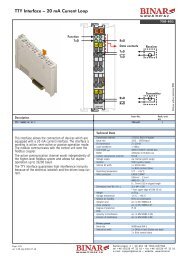
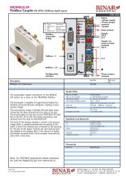
<strong>750</strong>-<strong>303</strong><br />
24 V<br />
1<br />
5<br />
24 V/0 V<br />
10nF<br />
DC<br />
DC<br />
Bus<br />
modules<br />
0V<br />
2<br />
6<br />
24 V<br />
24 V<br />
FIELDBUS INTERFACE<br />
ELECTRONICS<br />
3<br />
4<br />
7<br />
8<br />
0V<br />
0V<br />
10nF<br />
ELECTRONICS<br />
FIELDBUS<br />
INTERFACE<br />
<strong>750</strong>-<strong>303</strong><br />
Technical Data<br />
Max. no. of I/O modules 64<br />
Fieldbus<br />
Input process image<br />
max. 64 bytes<br />
Output process image<br />
max. 64 bytes<br />
Configuration<br />
via PC or PLC<br />
Voltage supply DC 24 V (-15 % ... +20 %)<br />
Input current max.<br />
500 mA at 24 V<br />
Efficiency of the power supply 87 %<br />
Internal current consumption 350 mA at 5 V<br />
Total current for I/O modules 1650 mA at 5 V<br />
Isolation<br />
500 V system /supply<br />
Voltage via power jumper contacts max. DC 24 V (-15 % ... +20 %)<br />
Current via power jumper contacts max. DC 10 A<br />
Operating temperature 0 °C ... +55 °C<br />
Wire connection CAGE CLAMP ®<br />
0.08 mm 2 ... 2.5 mm 2<br />
AWG 28 ... 14<br />
8 ... 9 mm /0.33 in stripped length<br />
Dimensions (mm) W x H x L 51 x 65* x 100<br />
* from upper edge of DIN 35 rail<br />
Weight<br />
ca. 195 g<br />
Storage temperature -25 °C ... +85 °C<br />
Relative air humidity<br />
95 % no condensation<br />
Vibration and acc. to IEC 60068-2-6<br />
shock resistance acc. to IEC 60068-2-27<br />
Degree of protection IP 20<br />
EMC<br />
Immunity to interference acc. to EN 50082-2 (96)<br />
Emission of interference acc. to EN 50081-2 (94)<br />
Item-No.<br />
Pack.-unit<br />
Variations<br />
pcs<br />
PROFIBUS DP 12 MBaud <strong>750</strong>-<strong>303</strong>/000-013 1<br />
Fieldbus<br />
Input process image<br />
max. 128 bytes<br />
Output process image<br />
max. 128 bytes<br />
Page Subject 2(4) to design changes<br />
ver 08.10.2001 1.02 eng 2002-09-09<br />
Batterivägen 4 • SE-461 38 TROLLHÄTTAN<br />
tel +46 (0)520 47 32 10 • fax +46 (0)520 47 32 10<br />
e-mail: support@binar.se • website: www.binar.se
Buscoupler PROFIBUS-DP – <strong>750</strong>-<strong>303</strong> BRIOS2<br />
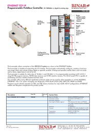
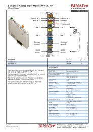
2. Node address<br />
The desired node address is set by<br />
means of the two encoding switches<br />
located on the buscoupler. The address<br />
is adjustable in the range of 0<br />
to 99.<br />
Address<br />
Ones<br />
x1<br />
9<br />
0<br />
1<br />
8 2<br />
Off 7 3<br />
6<br />
5<br />
4<br />
x1<br />
9 0 1<br />
8 2<br />
Off 7 3<br />
6 5 4<br />
x1<br />
x1<br />
9 0 1<br />
9 0 1<br />
8 2<br />
8 2<br />
7 3 Off 7 3<br />
6 5 4<br />
6 5 4<br />
The value of the switch at the bottom<br />
must be multiplied with 10, the value<br />
of the switch at the top must be<br />
added and this number is the value of<br />
the address.<br />
Address<br />
Tens<br />
x10<br />
9<br />
0<br />
1<br />
8 2<br />
7 3<br />
6<br />
5<br />
4<br />
<strong>750</strong>-<strong>303</strong><br />
x10<br />
9<br />
0<br />
1<br />
8 2<br />
7 3<br />
6<br />
5<br />
4<br />
x10<br />
9<br />
0<br />
1<br />
8 2<br />
7 3<br />
6<br />
5<br />
4<br />
x10<br />
9<br />
0<br />
1<br />
8 2<br />
7 3<br />
6<br />
5<br />
4<br />
The address should be set before<br />
switching on the buscoupler. Changing<br />
the address switches during operation<br />
does not affect the buscoupler<br />
address since it is read only during<br />
the power up sequence.<br />
Address 3 Address 17 Address 40<br />
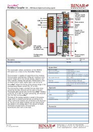
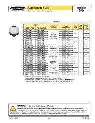
3 Diagnostic LEDs - fieldbus<br />
The fieldbus LEDs show the operating condition of the fieldbus. The functions of PROFIBUS are<br />
indicated by the LEDs “RUN”, “BF”, and “DIA”. The fourth LED available has no significance.<br />
LEDs Meaning Remedy<br />
RUN BF I/O RUN<br />
No function<br />
Test the voltage supply.<br />
OFF OFF OFF<br />
Power LED ON: Coupler defective<br />
Exchange coupler.<br />
Power LED OFF: No supply<br />
ON ON OFF<br />
ON OFF ON<br />
ON OFF OFF<br />
1. Coupler has left initialization and is ready for<br />
parameterization and configuration.<br />
2. Error in parameterization and/or configuration.<br />
3. Wrong station address.<br />
4. Break in the connection to the master (short<br />
circuit, wire break)<br />
RUN:<br />
Inputs are read, outputs are written.<br />
CLEAR:<br />
Inputs are read and outputs set.<br />
Start PROFIBUS-Master.<br />
Look for the projecting.<br />
Check the decimal switch.<br />
Check the bus cable.<br />
PLC stopped, another station<br />
does not work.<br />
RUN<br />
BF<br />
DIA<br />
I/O RUN<br />
I/O ERR<br />
4 Buscoupler startup and troubleshooting<br />
After configuration of the master connection and electrical installation of the fieldbus<br />
node/station, operation of the system can begin.<br />
After power to the Buscoupler and I/O modules has been applied, the Buscoupler verifies<br />
all internal functions, components and the communication interface by an internal diagnostic<br />
routine. Then the function modules and the existing configuration is determined.<br />
During the power up phase the ‘I/O ERR’ LED flashes with a high frequency. After a<br />
faultless power up the buscoupler enters the state ‘fieldbus start’. The green LED ‘RUN’<br />
indicates that the internal bus is operating normally.<br />
I/O RUN<br />
I/O ERR<br />
Page 3(4)<br />
ver 1.02 eng 2002-09-09<br />
ver 1.01 eng 2001-04-18<br />
Batterivägen 4 • SE-461 38 TROLLHÄTTAN<br />
tel +46 (0)520 47 32 10 • fax +46 (0)520 47 32 10<br />
e-mail: support@binar.se • website: www.binar.se
Buscoupler PROFIBUS-DP – <strong>750</strong>-<strong>303</strong> BRIOS2<br />
In case of a fault, the red ‘I/O ERR’ LED will continue flashing.<br />
By counting the number and frequency of flashes the fault can be easily identified quickly and accurately. A varying<br />
number of flashes and frequencies defines the fault. The table below describes the fault condition based on the<br />
counted number of ‘I/O ERR’ LED flashes.<br />
Sequence 1<br />
High frequency Pause<br />
Sequence 2<br />
Low frequency Pause<br />
Sequence 3<br />
Low frequency Pause<br />
I/O ERR<br />
Hardware and<br />
configuration error<br />
Error code Error argument<br />
No. of blinks No. of blinks Error description<br />
1<br />
0 EEPROM check sum error / check sum fault in parameter<br />
area of the flash memory.<br />
1 Overflow of the internal buffer memory for the inline code.<br />
2 Unknown data type.<br />
3 Module type of the flash program memory could not be determined<br />
/ is incorrect.<br />
4 Error during writing the flash memory.<br />
5 Error when deleting the flash memory.<br />
6 Changed I/O module configuration found after Autoreset.<br />
7 Invalid firmware.<br />
8 Timeout error serial EPROM.<br />
Additional<br />
configuration error<br />
2<br />
1 Process image is inactive at the switching operation Control<br />
or Monitor mode.<br />
2 Process image is bigger than the available cache.<br />
3 Error by the process image compilation.<br />
Internal bus<br />
command error<br />
3 0 Bus module(s) has (have) identified errors in the internal bus<br />
communication.<br />
Internal bus<br />
data error<br />
4<br />
0 Data error on internal bus or internal bus break at the bus<br />
coupler<br />
n* (n>0) internal bus break after module N, passive modules like supply<br />
terminal blocks do not count.<br />
Register<br />
communication error<br />
Fieldbus specific<br />
error<br />
I/O module<br />
not supported<br />
5 n* Internal bus error during register communication with the I/O<br />
module n.<br />
6 0 Number of I/O modules exceeded. The process image is<br />
bigger than the available cache.<br />
7 n* I/O module not supported at position n.<br />
Not used 8 - Not used<br />
CPU-TRAP-error 9 - Not used<br />
Blink code example:<br />
* The number of blink pulses (n) indicates the position of the I/O module.<br />
I/O modules without data are not counted (i.e. supply module without diagnostics).<br />
Assume that the 13th I/O module is removed. This will generate the following cyclically displayed blink sequence:<br />
1. The ‘I/O’ LED generates a fault display with the first blink sequence (red, approx. 10 Hz) and then pause.<br />
2. The first pause is followed by the second blink sequence (approx. 1 Hz). The ‘I/O’ LED blinks red four times<br />
and then pause. This indicates the error code 4 meaning an Internal bus data error.<br />
3. The second pause is followed by the third blink sequence (approx. 1 Hz). The ‘I/O’ LED blinks red twelve<br />
times and then pause. The error argument 12 means that the internal bus is interrupted after the 12th I/O<br />
module.<br />
After elimination of the fault, the buscoupler can only be set to the normal working condition by another POWER ON<br />
sequence.<br />
The green I/O RUN LED flashes when accessing the I/O modules internal data channels. After being switched on, the<br />
Buscoupler queries the configuration of the bus modules but does not carry out a data exchange with the I/O modules.<br />
This means that the red I/O ERR LED will extinguish after a faultless startup. The green I/O RUN LED indicates that<br />
data is being exchanged via the internal bus.<br />
Page 4(4)<br />
ver 1.02 eng 2002-09-09<br />
ver 1.01 eng 2001-04-18<br />
Batterivägen 4 • SE-461 38 TROLLHÄTTAN<br />
tel +46 (0)520 47 32 10 • fax +46 (0)520 47 32 10<br />
e-mail: support@binar.se • website: www.binar.se