MW3105 - Sefram
MW3105 - Sefram
MW3105 - Sefram

You also want an ePaper? Increase the reach of your titles
YUMPU automatically turns print PDFs into web optimized ePapers that Google loves.
<strong>MW3105</strong><br />
DIGITAL CLAMP MULTIMETER
2<br />
M <strong>MW3105</strong> A<br />
01
INTRODUCTION<br />
1.1 - Unpacking and inspection<br />
Upon removing your new Digital Clamp Meter from its packing, you should have the following items:<br />
1. Digital Clamp Meter.<br />
2. Test lead set (one black, one red).<br />
3. Carrying case.<br />
4. Instruction manual.<br />
5. Battery (installed).<br />
1.2 - Meter Safety<br />
Terms as marked on equipment:<br />
ATTENTION - Refer to manual.<br />
DOUBLE ISOLATION - (Protection Class II)<br />
DANGER - Risk of electric shock.<br />
3
Symbols in this manual<br />
This symbol indicates where cautionary or other information is found in the manual.<br />
Battery<br />
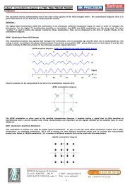
1.3 Front panel<br />
Refer to figure 1 and the following steps to familiarize yourself with the instrument’s front panel, controls and connectors.<br />
1. Hz F . Test lead input for frequency, resistance, capacitance, continuity and diode test measurements.<br />
2. Volt Plug . Positive (or high) test lead input for voltage measurements.<br />
3. COM Plug. Black (common neutral, ground), low side test lead input.<br />
4. Current Clamp Jaws. Use for current measurements without disconnecting circuit. Simply open jaws and loop around<br />
conductor.<br />
5. Lever. Press to open, or release to dose jaws.<br />
6. Power/Function/Range Selector. Rotary switch to turn power off or to select measurement range and function.<br />
4
7. Display, LCD Readout . Indicates function selected, data reading selected (PEAK, HOLD, etc.) over-range, polarity (-), and<br />
low battery status. Digit display: 3-3/4 digits with maximum reading 4000 for, with automatic placement of decimal point.<br />
8. HOLD. Press to freeze present reading at display and to display "HOLD" annunciator. Press again to exit.<br />
9. MAX/MIN. Press to record and enable display of minimum and maximum input levels. Press this button to increment through<br />
levels recorded and present input level. Display shows<br />
HOLD MAX or MIN and active level.<br />
10. PEAK. Push button store peak value of a varying input, PEAK displayed. Press to toggle in and out.<br />
11. ZERO. Push button to obtain difference between a stored reference and present reading, ZERO displayed. Stored<br />
reference is input level when ZERO data mode is enabled. Press and hold button down for at least 2 seconds to exit.<br />
12. RANGE. Button to select manual range mode and to increment present range; shown at display, in this mode, each<br />
time button is pressed range increments by 0.1. Range starts from active autoranging level. To exit, press and hold down this<br />
button for about 2 seconds.<br />
13. Bargraph. Provides analog display of magnitude and direction of change of input; 42 segments<br />
5
Figure 1<br />
6
SPECIFICATIONS<br />
2.1 General specifications<br />
Display : 3 ¾ digit LCD with a maximum reading of 3999<br />
Polarity : Automatic polarity indicated. « - » shown, « + » assumed.<br />
Measuring Rate : Nominal, 2 mes/sec.; Cap. & Freq., 1 mes/sec.<br />
Overrange Indication: OL shown, all digits blank.<br />
Low Battery Indication: symbol shown at about 7.4 V, or less.<br />
Power Requirement: Single 9 V battery (NEDA 1604A, 6F22).<br />
Battery Life : 100 hours typical (with alkaline)<br />
Jaw opening : 57mm (2.24’’).<br />
Position error : Add 1% to specified accuracy if conductor is not centered in jaws.<br />
Dimensions (H x W x D) : 277 x 102 x 49 mm (10.9" x 4" x 1.9").<br />
Weight : 540 g (18.9 oz), includes battery.<br />
Accessories supplied: battery, carrying case, test leads, instruction manual.<br />
Temperature coefficient: 0.1 x specified accuracy/°C (28 °C)<br />
Auto Power OFF : if not used, turns meter off after 30 minutes typical.<br />
7
2.2 Environmental conditions<br />
Indoor use only<br />
Maximum altitude of use: 2000 meters.<br />
Operating temperature : 0 °C to 50 °C,
2.3 Electrical Specifications<br />
Accuracy is given as ±(% of reading + number of digits) from 18 °C to 28 °C, with relative humidity up to 70%.<br />
Temperature coefficient: 0.1 x specified accuracy/°C (t 28 °C).<br />
DC Current - Manual ranging<br />
Range Resolution Accuracy Overload Protection<br />
400A 100mA ( 1.5% + 5 dgt)<br />
1000A 1A 0-600A ( 1.5% + 5 dgt) 1200A for 60 s maximum<br />
600-800A ( 2.5% + 5 dgt)<br />
800-1000A ( 3.5% + 5 dgt)<br />
Specifications given from 5% to 100% of the range. Accuracy given after having performed auto-zero of the clamp.<br />
AC Current - Manual ranging<br />
Range Resolution Accuracy 50-60Hz Accuracy 60-400Hz Overload<br />
Protection<br />
400A 100mA ( 1.5% + 5 dgt) ( 3.0% + 5 dgt)<br />
1000A 1A 0-600A ( 1.5% + 5 dgt) 0-600A ( 3.0% + 5 dgt)<br />
600-1000A ( 2.0% + 5 dgt) 600-1000A ( 3.5% + 5 dgt)<br />
Specifications given from 5% to 100% of the range.<br />
Crest factor : 3 max. Add 1% to accuracy for crest factor between 2 and 3.<br />
9<br />
Conversion : TRUE RMS.<br />
1200A for 60 s<br />
maximum
DC Voltage (using test leads, auto or manual ranging)<br />
Range Resolution Accuracy Input Impedance<br />
400mV 100µV > 1000M<br />
4V 1mV 11M<br />
40V 10mV ( 0.5% + 1 dgt) 10M<br />
400V 100mV 10M<br />
1000V 1V 10M<br />
Overload protection : 1000V DC or 750 VAC RMS.<br />
10
AC Voltage (using test leads, auto or manual ranging)<br />
Range Resolution Accuracy Input Impedance Overload protection<br />
50Hz to 500Hz<br />
400mV* 100µV > 1000M // 100pF<br />
4V 1mV 11M // 100pF 1000V DC or<br />
40V 10mV ( 1.5% + 4 dgt) 10M // 100pF 750V AC RMS<br />
400V 100mV 10M // 100pF<br />
1000V 1V 10M // 100pF<br />
Specifications given from 5% to 100% of the range (except 400mV range, see *)<br />
Conversion : TRUE RMS<br />
Crest factor : 3 max. Add 1% to accuracy for crest factor between 2 and 3<br />
* Input signal >40mV, bandwidth 50-100Hz for this range.<br />
11
Resistance (using test leads, auto and manual ranging)<br />
Range Resolution Accuracy Open circuit voltage Overload protection<br />
400 0.1 ( 1.2% + 4 dgt) 0.4V<br />
4K 1 ( 1.0% + 2 dgt) 0.4V<br />
40K 10 ( 1.0% + 2 dgt) 0.4V 500V DC or<br />
400K 100 ( 1.0% + 2 dgt) 0.4V AC RMS<br />
4M 1K ( 1.5% + 4 dgt) 0.4V<br />
40M 10K ( 2.0% + 4 dgt) 0.4V<br />
Continuity Test (using test leads)<br />
Range Threshold Response time Test current<br />
400 < 40 100ms typ.
Diode Test (using test leads)<br />
Range/Resolution Accuracy Open circuit voltage Test current<br />
4V / 1mV ( 1.0% + 2 dgt) 3.2V about 0.6mA<br />
Overload Protection : 500V DC or AC RMS<br />
Frequency (using test leads, auto or manual ranging)<br />
Range Resolution Accuracy Trigger level Overload protection<br />
100Hz 0.01Hz ( 0.1% + 10 dgt)<br />
1kHz 0.1Hz ( 0.1% + 4 dgt) 500V DC<br />
10kHz 1Hz ( 0.1% + 4 dgt) 2.5 V RMS or AC RMS<br />
100kHz 10Hz ( 0.1% + 8 dgt)<br />
400kHz 100Hz ( 0.1% + 20 dgt)<br />
NOTE: Frequencies 100khz, readings may tend to be unstable.<br />
Minimum frequency : 1Hz<br />
13
Capacitance (using test leads, auto and manual ranging)<br />
Range Resolution Accuracy Overload protection<br />
4nF 1pF ( 1.5% + 40 dgt)*<br />
40nF 10pF ( 1.5% + 4 dgt)*<br />
400nF 100pF ( 1.5% + 4 dgt) 500V DC or<br />
4µF 1nF ( 1.5% + 4 dgt) AC RMS<br />
40µF 10nF ( 1.5% + 4 dgt) for C
OPERATION<br />
This instrument has been designed and tested in accordance with IEC Publication 1010, Safety Requirements for<br />
Electronic Measuring Apparatus and has been supplied in a safe condition. This instruction manual contains some<br />
information and warnings which have to be followed by the user to ensure safe operation and to retain the instrument<br />
in safe condition.<br />
3.1 Precaution and preparations for measurements<br />
1. Read, thoroughly understand and follow the SAFETY instructions given in this manual.<br />
2. Examine your test leads. Make sure they are in good condition, free from cracks, etc., and that they make good contact with<br />
the plugs of your meter. Do this for safe operation and to avoid false readings.<br />
3. Before taking a measurement, review the related instructions in this manual.<br />
4. Before taking a measurement, estimate its expected value. If you are considerably out of an expected range, carefully review<br />
your circuit under test; it could be defective.<br />
5. If value of measurement is unknown, start with the highest range.<br />
6. Stay within the operating range of your meter. Never exceed the 750 V AC or 1000 V DC maximum limits and 500 V from<br />
COM plug to earth ground or reference.<br />
7. If an over-range is shown, immediately switch to a higher range.<br />
CAUTION<br />
Never switch between ranges while connected to high voltage. This prevents damage to the instrument.<br />
15
8. When using the jaws to take a measurement, center a single conductor of a cable in the jaws and perpendicular to the jaws<br />
to avoid false readings. When two or more conductors are in the jaws when an AC reading is taken, current flows in each<br />
wire tend to cancel each other. Off center wires produce lower readings.<br />
9. For reliable measurements, replace battery when the low battery symbol appears on display. See MAINTENANCE<br />
instructions to replace battery.<br />
10. Set function selector to OFF when not in use to conserve battery power.<br />
3.2 VOLTAGE MEASUREMENTS (Use these instructions for AC and DC measurements).<br />
CAUTION<br />
Never try to measure voltages greater than 750V AC or 1000V DC.<br />
1. Select AC or DC voltage and range. lf range is unknown, start with the highest range. Set function selector to V= for DC<br />
measurements or to V ~ for AC measurements.<br />
2. Plug red test lead to VOLT plug, black test lead to COM plug.<br />
3. Connect black test lead to common of circuit, red lead to point being measured at this circuit.<br />
4. Value at display is actual level being measured, + assumed, - (negative) shown. In AUTO mode only: decimal point is<br />
correctly located for best resolution.<br />
16
CAUTION<br />
Never switch between ranges while connected to high voltage to avoid personal harm and/or damage to the meter.<br />
6. Disconnect test leads from voltage source then switch meter to OFF to conserve power.<br />
3.3 RESISTANCE / CONTINUITY MEASUREMENTS<br />
CAUTION<br />
Remove power from circuit under test before making resistance measurements.<br />
1. Verify that power is off and that any capacitors are discharged in circuit about to be tested.<br />
2. For resistance measurements: In AUTO (default) mode, set function selector to Range is automatically selected for best<br />
resolution. If the meter is operating in manual ranging mode, select range that closely matches actual resistance expected.<br />
3. For continuity measurements:<br />
Set function selector to position.<br />
Plug black test lead into COM plug. Plug red test lead into HzF plug.<br />
5. Connect test leads across desired measuring points.<br />
17
6. Resistance measurements: Read resistance at display in , k, or M as shown by annunciator symbol.<br />
Continuity measurements: Audible tone sounds when resistance is less than about: 40 ohms.<br />
7. Switch meter to OFF when readings are done to conserve battery power.<br />
3.4 DIODE TESTS<br />
CAUTION<br />
Remove power from circuit under test before making diode measurements.<br />
1. Verify that power is off and that any capacitors are discharged in circuit about to be tested.<br />
2. Set function selector to position.<br />
Continuity is the default symbol.<br />
3. Plug black test lead into COM plug. Plug red lead into HzF plug.<br />
4. Connect black test lead to cathode of diode, red test lead to its anode. Typical forward voltages should be about as follows:<br />
Silicone diode: 0.7 V.<br />
Germanium diode: 0.3 V.<br />
5. Reverse test leads, black to anode, red to cathode. Voltage reading should be: 3.1V.<br />
6. Note: Make sure that correct reading is obtained in forward and reverse positions. If diode is partially shorted, the same or<br />
higher reading may be obtained in both positions. If diode is open, an overload OL may be shown in both positions.<br />
7. Switch meter to OFF to conserve power when tests are done.<br />
18
3.5 AC CURRENT MEASUREMENTS<br />
CAUTION<br />
Never try to measure currents where the maximum voltage between any conductor and ground exceeds 500 V to avoid<br />
personal harm and/or damage to the meter.<br />
1. Remove test leads from meter.<br />
2. Set function selector to A ~ for AC current measurements and choose range. If range is unknown, start with the highest<br />
range, 1000A.<br />
3. Press trigger on left side of meter to open jaws. Now, damp around a single conductor so it's centered and perpendicular in<br />
the jaws as shown in following illustration. Release trigger to damp jaws and make sure they are fully dosed.<br />
NOTE : Position jaws around only one conductor centered and perpendicular to jaws. If jaws are placed around two or more<br />
current carrying conductors reading will be false. For example, if damped around the line cord of an AC appliance, currents<br />
flowing through the cord tend to cancel each other giving a false reading.<br />
4. Read current level at display. If needed for better resolution, select a lower range.<br />
3.6 DC CURRENT MEASUREMENTS<br />
1. Set function selector to A = for DC current measurements and select range. lf range is unknown, start with the highest range,<br />
1000A.<br />
2. There may be a residual reading on the meter. Press the ZERO button to zero the meter.<br />
3. Clamp jaws around the conductor and read current level from display.<br />
19
4. For maximum accuracy, remove the jaws from around the conductor and press the ZERO button again the meter, Then<br />
repeat the measurement and use the second reading.<br />
3.7 FREQUENCY MEASUREMENTS<br />
1. Set function selector to Hz position. AUTO mode is on, range is automatically selected.<br />
2. Plug black test lead into COM plug. Plug red test lead into HzF plug.<br />
3. Connect test leads across desired measuring points. Make sure that peak of frequency signal does not exceed 500 V DC or<br />
AC.<br />
4. Switch meter to OFF to conserve power.<br />
20
3.8 CAPACITANCE MEASUREMENTS<br />
CAUTION<br />
1. Discharge capacitors before connecting to the meter. Capacitors should not be measured "in circuit”. Parallel<br />
components will invalidate the measurement.<br />
2. Verify that power is off and that any capacitors are discharged in circuit about to be tested. A capacitor can be safely<br />
discharged by connecting a 100 k resistor across its leads.<br />
3. Set function selector to capacitor position.<br />
4. Plug black test lead into COM plug. Plug red lead into HzF plug.<br />
5. Touch test leads to leads of capacitor. Be sure to observe polarity when testing polarized capacitors. Read capacity in µF at<br />
display.<br />
6. Accuracy Note: Measurement accuracy can be improved by first selecting the ZERO feature. Next, zero the display which<br />
automatically subtracts any residual capacitance in the meter and test leads. After zeroing, take your measurement. The<br />
new reading will be the true capacitance, residual capacitance subtracted from total capacitance.<br />
7. Switch meter to OFF to conserve power.<br />
3.9 AUTO POWER OFF<br />
Auto Power Off is a feature that conserves battery power when you forget to turn the power off. When the Function switch<br />
position has not been changed for about 30 minutes, the meter automatically turns off. If you are using the meter to make<br />
several measurements without changing the position of the Function switch, the meter may turn off. To restart, simply rotate the<br />
Function switch at least one position.<br />
21
3.10 MANUAL RANGING<br />
The meter normally operates in the autoranging mode, but may be switched to manual ranging by the RANGE button.<br />
The first press of the RANGE button switches the meter from autoranging to the manual ranging mode and the<br />
annunciator is displayed. The range does not change. With each additional press of the RANGE button, the meter steps to the<br />
next higher range until the highest range is reached, then it steps to lowest range. When a range is exceeded, a series of<br />
"beeps" are emitted until the correct range is reached. When any of the following modes are selected, the meter is automatically<br />
reverts to manual ranging. It may be necessary to preselect the correct range before making these measurements: MAX/MIN,<br />
HOLD, PEAK HOLD and Relative Mode.<br />
To exit manual ranging mode and return to autoranging, hold the RANGE button down for about 2 seconds. The range symbol<br />
will disappear from the display and the AUTO annunciator will reappear.<br />
3.11 DATA HOLD<br />
The Data Hold feature permits the displayed reading to be frozen. For example, when damped around a conductor where light<br />
conditions are poor, press the H HOLD button. The reading is frozen and can be read after unclamping the meter and bringing it<br />
into the light. While the Data Hold mode is enabled, the HOLD annunciator is displayed. Press the H HOLD button a second<br />
time to exit this mode. The HOLD annunciator disappears from the display.<br />
3.12 MAX/MIN HOLD<br />
The MAX/MIN HOLD feature permits recording the lowest and highest value of a changing measurement.<br />
The first press of the MAX/MIN button enables the MAX/MIN Record mode. The highest and lowest values measured since<br />
22
entering this mode are recorded and stored in memory. MAX or MIN or present values can be reviewed by successive presses<br />
of the MAX/MIN button. When MIN and HOLD are displayed, the reading shown is the "lowest" since entering this mode. When<br />
MAX and HOLD are displayed, the reading shown is the "highest" since entering this mode. When neither MAX nor MIN nor<br />
HOLD are displayed, but the manual ranging symbol remains, the present value is displayed and recording continues.<br />
Auto Power Off is overridden in the MAX/MIN Record mode so that recording may be extended for many hours if desired. To<br />
use the MAX/MIN Record mode properly, first connect the test leads to the point of measurement and then wait for the reading<br />
to stabilize. After it stabilizes, press the MAX/MIN button. If the button is pressed before the test leads are connected, the MIN<br />
reading will be zero. Also, the meter reverts to manual range operation upon entering the MAX/MIN Record mode. if the test<br />
leads are not yet connected, the meter will remain in the lowest range and may over-range when connected. If the variation<br />
swing of the value is great, it may be necessary to manually step to a higher range to prevent an over-range condition on the<br />
MAX value.<br />
To exit the MAX/MIN Record mode, hold the MAX/MIN button down for about 2 seconds.<br />
The MAX/MIN Record mode operates at the speed of the display update, about 2 times per second. That is, it records the MAX<br />
or MIN reading of the display. The speed of acquisition in this mode differs (slower) from the PEAK HOLD operation.<br />
3.13 PEAK HOLD<br />
The PEAK HOLD feature allows measurement of a peak value, for example, the starting current of a motor.<br />
To measure peak current, clamp the meter jaws around the conductor and place the meter in a PEAK HOLD mode before<br />
starting the current. Select AC current, meter reverts to manual ranging, then press the P PEAK button twice so the HOLD P<br />
annunciator is displayed along with manual range indicator.<br />
23
When measuring AC or DC voltage, frequency and resistance peak values with the meter, test leads are used. The general<br />
operation is similar to the description given for measuring current. When measuring AC or DC voltage and frequency, just as<br />
when measuring current, the meter is connected to the source being measured before power is applied. The remaining<br />
operation follows the description outlined for AC current. Peak resistance measurements must be made with the power off.<br />
PEAK HOLD operates very fast, in a few milliseconds, long before it's shown at the display.<br />
Exit the PEAK HOLD mode by holding the P PEAK button down for about 2 seconds.<br />
3.14 RELATIVE MODE<br />
Relative mode ( ZERO) permits measurements with respect to a reference other than zero. First, measure a value for use as<br />
your reference, then press the ZERO button. ZERO is now displayed and the meter REFERENCE READING reverts to<br />
manual ranging. The reference value now becomes zero. All subsequent measurements are "relative" to the reference value.<br />
For example, for a reference of 316 ohms, first measure a 316 ohm value. Upon entering the ZERO mode, a value of 316<br />
ohms becomes zero, 320 ohms is read as 4 and 310 ohms is read as -6. If the variation from the reference is too great, an<br />
overrange may occur signaled by beeps. When this happens, up-range the meter then reestablish ZERO reference on the<br />
new range.<br />
To exit the relative mode, hold the ZERO button down for about 2 seconds.<br />
24
MAINTENANCE<br />
WARNING<br />
Remove test leads before changing batteries. Never operate instrument with battery compartment open.<br />
CAUTION<br />
Remove discharged batteries immediately to prevent damage from battery leakage.<br />
BATTERY REPLACEMENT<br />
The low battery symbol on the display indicates that battery power under load has dropped to about 7.4 V. The meter may still<br />
be used for a short time afterwards; however, replace the battery as soon as possible.<br />
The battery compartment cover is located at the rear of the case - near bottom. To replace battery, remove screw in cover then<br />
remove cover. The meter uses a standard 9 V (NEDA 1604A / 6F22) battery. After replacing battery, be sure to replace cover<br />
and tighten screw to secure the compartment.<br />
HELPFUL HlNT, TEST LEADS<br />
Only use the safety type test leads like those supplied with this meter for safe operation and to avoid false readings. Periodically<br />
inspect these test leads to ensure that the conductors are not intermittent, corroded or broken. Keep the plug area of the meter<br />
free of dirt.<br />
Inspect the test leads for breaks in the insulation and replace as necessary.<br />
25
SEFRAM INSTRUMENTS & SYSTEMES<br />
32, rue Edouard MARTEL<br />
42100 SAINT-ETIENNE ( FRANCE)<br />
Declares, that the below mentioned product complies with :<br />
DECLARATION OF CE CONFORMITY<br />
according to EEC directives and NF EN 45014 norm<br />
The European low voltage directive 73/23/EEC :<br />
NF EN 61010-1 Safety requirements for electrical equipment for measurement, control and laboratory use.<br />
The European EMC directive 89/336/EEC, amended by 93/68/EEC :<br />
Emission standard EN 50081-1.<br />
Immunity standard EN 50082-1.<br />
Installation category: 600 V Cat II – 300 V Cat III<br />
Pollution degree: 2<br />
Product name :<br />
Model :<br />
Clamp Meter<br />
<strong>MW3105</strong><br />
Compliance was demonstrated in listed laboratory and record in test report number: RC 3105<br />
SAINT-ETIENNE : Name/Position :<br />
December 1 sț 1997<br />
T. TAGLIARINO / Quality Manager<br />
26
SEFRAM<br />
32, rue Edouard Martel<br />
BP 55<br />
42009 – SAINT-ETIENNE Cedex 2<br />
France<br />
Tel : 0825 56 50 50 (0,15€TTC/mn) or +33 4 77 59 36 81<br />
Fax : +33 4 77 57 23 23<br />
Web : www.sefram.fr<br />
E-mail : sales@sefram.fr<br />
28