MULTICAL® 601 & ULTRAFLOW® 14
MULTICAL® 601 & ULTRAFLOW® 14
MULTICAL® 601 & ULTRAFLOW® 14

You also want an ePaper? Increase the reach of your titles
YUMPU automatically turns print PDFs into web optimized ePapers that Google loves.
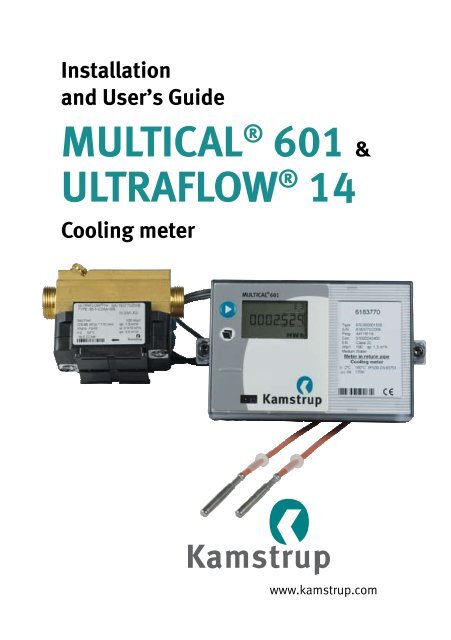
Installation<br />
and User’s Guide<br />
MULTICAL ® <strong>601</strong> &<br />
ULTRAFLOW ® <strong>14</strong><br />
Cooling meter<br />
www.kamstrup.com
Operation conditions<br />
Operation conditions/measuring ranges:<br />
Calculator q: 2°C…180°C DΘ: 3K…170K<br />
Temperature sensor pair q: 2°C…50°C DΘ: 3K…30K<br />
Flow sensor<br />
q: 2°C…50°C<br />
Mechanical environment:<br />
M1 (fixed installation with minimum vibration).<br />
Electromagnetic environment:<br />
E1 (Domestic and light industrial). Signal cables from the meter must be<br />
separated by at least 25 cm distance to other installations.<br />
Climatic environment:<br />
The installation of MULTICAL ® shall be made in non-condensing environments<br />
and in closed location (indoor). The ambient temperature must be within<br />
5…55°C.<br />
Maintenance and repair:<br />
The energy supplier is allowed to change communication module, battery and<br />
temperature sensor pair. The flow part must not be separated from the base<br />
unit that contains the flow sensor electronics. All repairs require a following<br />
calibration on an accredited laboratory.<br />
MULTICAL ® <strong>601</strong>, type 67-C is suitable for temperature sensors type Pt500.<br />
Battery for replacement: Kamstrup type 66-00-200-100.
MULTICAL ® <strong>601</strong> & ULTRAFLOW ® <strong>14</strong><br />
English<br />
installation<br />
Kamstrup A/S<br />
Industrivej 28, Stilling, DK-8660 Skanderborg<br />
TEL: +45 89 93 10 00 · FAX: +45 89 93 10 01<br />
info@kamstrup.com · www.kamstrup.com
1.<br />
General information<br />
Read this guide before installing the energy meter. If the meter is installed<br />
incorrectly, Kamstrup’s guarantee obligations will no longer apply.<br />
Please note that the following installation conditions must be obeyed:<br />
- Pressure stage ULTRAFLOW ® : PN16/PN25, see marking. Marking of flow<br />
part does not cover included accessories<br />
- Pressure stage Kamstrup<br />
sensor set type DS:<br />
- Pressure stage Kamstrup<br />
stainless steel pockets:<br />
PN16<br />
PN25<br />
2.<br />
Mounting of temperature sensors<br />
Temperature sensors used to measure flow and return temperatures make<br />
up a matched pair of sensors and must never be separated.<br />
Usually, MULTICAL ® <strong>601</strong> is supplied with mounted temperature sensors. The<br />
cable length must not be changed. Replacement of sensors, if required, must<br />
always be made in pairs.<br />
One sensor is marked with a red sign, and must be installed in the flow pipe<br />
(cold pipe). The other sensor is marked with a blue sign, and must be installed<br />
in the return pipe (warm pipe).<br />
2.1 Pocket sensor pair<br />
Preferably, sensor pockets must be mounted in tee-pieces or in 45°C lateral<br />
Y-pieces. The tip of the sensor pocket must be placed pointing towards the<br />
flow direction and in the middle of the water flow.<br />
Temperature sensors must be mounted from below.<br />
2
Temperature sensors should be inserted to the bottom of the pockets. If a quick<br />
response time is required, “non-hardening” heat conducting paste can be<br />
used.<br />
Push the plastic sleeve on the sensor cable into the sensor pocket and secure<br />
the cable with the supplied M4 sealing screw. Fasten the screw with your<br />
fingers only. Seal the pockets using seal and sealing wire.<br />
2.2 Short direct temperature sensor set<br />
The short direct sensor can be mounted in special ball valves or in special<br />
angle tee-pipes, both with threads up to R1 and built-in M10 union for the<br />
short direct sensor.<br />
For mounting in existing heating installations with standard angle tees<br />
Kamstrup A/S can also supply R½ and R¾ brass nipples which fit the short<br />
direct sensors.<br />
The short direct sensor can also be fitted directly into all ULTRAFLOW ® variants<br />
from Kamstrup A/S with G¾ and G1 thread on the meter case. Fasten the brass<br />
unions of the sensors lightly (approx. 4 Nm) by means of a 12 mm face wrench,<br />
and seal the sensors with seal and wire.<br />
Temperature sensors must be mounted from below.<br />
3
3.<br />
Information codes “E”<br />
MULTICAL ® <strong>601</strong> constantly monitors a series of important functions. If a serious<br />
error occurs in the measuring system or in the installation, an “Info” appears<br />
in the display and an info code can be read by activating the upper front plate<br />
button until the measuring unit shows an “Info” in the display. The info code is<br />
only visible while the error exists.<br />
Info code Description Response time<br />
0 No irregularities -<br />
1 Supply voltage has been cut off -<br />
8 Temperature sensor T1 outside measuring range 1…10 min.<br />
4 Temperature sensor T2 outside measuring range 1…10 min.<br />
ULTRAFLOW ® X4 info (if activated CCC=4XX)<br />
16 Flow sensor V1, Datacomm error After reset and 1 day (00:00)<br />
2048 Flow sensor V1, Wrong meter factor After reset and 1 day (00:00)<br />
4096 Flow sensor V1, Signal too low (Air) After reset and 1 day (00:00)<br />
16384 Flow sensor V1, Wrong flow direction After reset and 1 day (00:00)<br />
4.<br />
Mounting of flow sensor<br />
Before mounting the flow sensor, flush the system thoroughly and remove<br />
protection plugs/plastic membranes from the flow sensor. Correct flow sensor<br />
position (flow or return pipe) appears from the front label placed on the<br />
MULTICAL ® <strong>601</strong>. The flow direction is indicated by an arrow on the side of the<br />
flow sensor.<br />
Gasket<br />
Gasket<br />
Torgue approx. 4 Nm<br />
4<br />
Glands and gaskets must be mounted as shown on the above drawing.<br />
Straight inlet: ULTRAFLOW ® requires neither straight inlet nor outlet to meet<br />
the Measuring Instruments Directive (MID) 2004/22/EC, OIML R75:2002 and<br />
EN <strong>14</strong>34:2007. Only in case of heavy flow disturbances before the meter will a<br />
straight inlet section be necessary. We recommend to follow the guidelines in<br />
CEN CR 13582.<br />
To prevent cavitation, the operating pressure at the ULTRAFLOW ® must be min.<br />
1.5 bar at qp and min. 2.5 bar at qs.<br />
ULTRAFLOW ® must not be exposed to pressures below ambient pressure<br />
(vacuum).
®<br />
4.1 Mounting of ULTRAFLOW<br />
90° 90°<br />
ULTRAFLOW ® must be mounted vertically,<br />
horizontally or at any angle in between.<br />
Max. 45°<br />
ULTRAFLOW ® may be turned up to<br />
45° in relation to horizontal.<br />
The ULTRAFLOW ® housing must<br />
not be mounted facing upwards<br />
or downwards.<br />
5
4.1.1 Humidity and condensation<br />
When installed in humid environments ULTRAFLOW ® must be turned 45° in<br />
relation to horizontal as shown below.<br />
45°<br />
5.<br />
Mounting of the calculator<br />
The MULTICAL ® <strong>601</strong> calculator can be mounted in two different ways:<br />
5.1 Separately/wall mounting<br />
52 mm<br />
The wall bracket gives you the opportunity<br />
of mounting MULTICAL ® <strong>601</strong> directly on an<br />
even wall. Use the bracket as a template to<br />
mark and drill two holes with a diameter of<br />
6 mm in the wall.<br />
Installation of calculator<br />
6<br />
Front, vertical<br />
Front, at an angle<br />
between horizontal<br />
and vertical<br />
Front, horizontal
Note! Cables must be installed from below.<br />
Installation example with suspension.<br />
Note: The suspension must not be used on condensing pipes.<br />
Suspension kit item no. 5915-1<strong>14</strong>. Not included<br />
5.2 Panel mounting<br />
MULTICAL ® <strong>601</strong> can be mounted directly into panels by means of Kamstrup’s<br />
panel mounting kit, no. 66-99-104 (192 x <strong>14</strong>4 mm).<br />
6.<br />
Power supply<br />
MULTICAL ® <strong>601</strong> can be power supplied by means of a built-in lithium battery,<br />
an internal 24 VAC mains module or an internal 230 VAC mains module.<br />
The two wires from the battery or mains module are mounted in terminals 60<br />
and 61 of the calculator.<br />
The polarity has to be correct; connect the red wire to terminal no. 60 (+)<br />
and the black wire to terminal no. 61 (-).<br />
7
6.1 Battery supply<br />
MULTICAL ® <strong>601</strong> is connected to a lithium battery, D-cell. The battery is marked<br />
with installation year, e.g. 2007, as well as production date.<br />
Optimal battery life is obtained by keeping the battery temperature below 30°C,<br />
e.g. by wall mounting.<br />
The voltage of a lithium battery is almost constant throughout the whole<br />
lifetime of the battery (approx. 3.65 V). Therefore, it is not possible to determine<br />
the remaining capacity by measuring the voltage.<br />
The battery cannot and must not be charged and must not be short-circuited.<br />
Used batteries must be handed in for approved destruction, e.g. at Kamstrup’s.<br />
6.2 Mains modules<br />
The modules are protection class II and are connected via a two-wire cable<br />
(without earth) through the cable bush of the calculator placed in the right<br />
side of the connecting base. Use a connecting cable with an outer diameter<br />
of 5–10 mm and ensure correct dismantling as well as correct mounting of<br />
the cable relief.<br />
Max. permitted fuse: 6 A<br />
National installation regulations must be obeyed..<br />
Black<br />
Red<br />
Black<br />
Red<br />
24 VAC<br />
E.g. transformer 230/24 V,<br />
type 66-99-403 can be used.<br />
230 VAC<br />
This module is used for direct mains<br />
connection.<br />
NB! MULTICAL ® <strong>601</strong> cannot<br />
be supplied from 24 VDC.<br />
7.<br />
Operational check<br />
Carry out a operational check when the energy meter has been fully mounted.<br />
Open the thermo-regulators and cocks in order to establish a water flow<br />
through the heating system. Activate the upper push button on the<br />
MULTICAL ® <strong>601</strong> and check that the display values for temperature and<br />
water flow are reliable.<br />
8
8.<br />
Electrical connection<br />
The polarity of the temperature sensors T1 and T2 is<br />
unimportant.<br />
Use below colours at the flow sensors V1 and V2<br />
when connecting the ULTRAFLOW ® and electronic<br />
pick-up units.<br />
Terminal<br />
No.<br />
Standard<br />
measurement of heat and cooling<br />
T1 5–6 Sensor in flow pipe (red)<br />
T2 7–8 Sensor in return pipe (blue)<br />
9.<br />
Plug-in modules<br />
MULTICAL ® <strong>601</strong> can be extended with a number of extra functions in the form<br />
of plug-in modules. Below is a short description of the individual modules.<br />
9.1 Data + pulse inputs<br />
Data terminals are e.g. used for connecting a PC.<br />
The signal is passive and galvanically separated<br />
through optocouplers. Conversion into RS232 level<br />
requires connection of data cable 66-99-106 (D-Sub<br />
9F) or 66-99-098 (USB) with the following connections:<br />
62 Brown (DAT)<br />
63 White (REQ)<br />
64 Green (GND)<br />
NB! If data reading must be compatible with MULTICAL ® 66-CDE, top module<br />
67-06 must be used in MULTICAL ® <strong>601</strong>.<br />
The pulse inputs can be used for connecting electricity and water meters.<br />
Please note the maximum pulse frequency and correct pulse coding (l/pulse<br />
and Wh/pulse) which are selected by means of the FF and GG configuration.<br />
65 - 66 Input A<br />
67 - 68 Input B<br />
9
9.2 M-Bus, type 67-00-04/08/20<br />
M-Bus can be mounted in star, ring or bus topology. Depending on the<br />
power supply of the M-Bus Master as well as the total cable resistance, up<br />
to 250 meters can be connected.<br />
Cable resistance<br />
Cable capacity<br />
< 29 Ohm<br />
< 180 nF<br />
25 24<br />
The M-Bus network is to be connected to<br />
terminals 24 and 25. The polarity is unimportant.<br />
M-Bus is supplied with pulse inputs.<br />
NB! 67-00-04/08 requires installation of top<br />
modules type 67-06.<br />
9.3 Radio + pulse inputs, type 67-00-0A/0B/25/26<br />
The radio module is used for wireless communication via a<br />
license-free radio frequency and is available for internal or<br />
external antenna.<br />
For further information on radio please refer to<br />
Technical Description for Radio (5512-013).<br />
The pulse inputs in this module are identical with<br />
the ones described earlier.<br />
NB! 67-00-0A/0B requires installation of top module type<br />
67-06.<br />
Type 67-00-21 includes radio and router funtions.<br />
10
9.4 Analog outputs<br />
Type 67-00-23, see Installations manual 5512-369 (DK-GB-DE).<br />
9.5 Lon Works<br />
Type 67-00-24, see Installations manual 5512-396 (DK) or 5512-403 (GB).<br />
9.6 Top modules<br />
Type 67-01: RTC (Real Time Clock)<br />
The top module consists of real time clock and<br />
battery backup.<br />
When the MULTICAL ® <strong>601</strong> calculator top is placed<br />
in the connecting bracket and is powered, current<br />
date and time is transferred from the top module to<br />
the calculator.<br />
The top module is recommended for applications in<br />
which correct date/time in data loggers as well as in<br />
time-controlled tariff is considered important.<br />
Real time clock and battery backup are standard<br />
features in all other top modules.<br />
Terminal screws are not used in this module.<br />
Type 67-06: RTC + 66-C compatibility + pulse<br />
outputs<br />
The top module makes MULTICAL ® <strong>601</strong> data<br />
compatible with MULTICAL ® 66-C making it<br />
possible to use many of the previous base modules<br />
for MULTICAL ® 66-C in MULTICAL ® <strong>601</strong> too.<br />
Furthermore the top module has two pulse outputs<br />
for energy (CE) and volume (CV) respectively. The<br />
pulse resolution follows the display (determined in<br />
the CCC-code). E.g. CCC=119 (qp 1.5): 1 pulse/kWh<br />
and 1 pulse/0.01 m 3 . The pulse width is 32 ms.<br />
The pulse outputs are optoinsulated and stand<br />
30 VDC and 10 mA.<br />
11
Type 67-07: RTC + M-Bus<br />
M-Bus can be connected in star, ring and bus<br />
topology.<br />
Depending on the M-Bus Master and the cable<br />
length/cross section, up to 250 meters can be<br />
connected with primary addressing, and even more<br />
if secondary addressing is used.<br />
Cable resistance in network: < 29 Ohm<br />
Cable capacity in network: < 180 nF<br />
The connection polarity of terminals 24-25 is<br />
unimportant.<br />
Normally the primary address consists of the last<br />
digits of the customer number (000-250), but it<br />
can be changed via the PC program METERTOOL.<br />
Type 67-08: RTC + hourly data logger + pulse<br />
outputs<br />
This top module has two configurable pulse<br />
outputs, which are suitable for volume and<br />
energy pulses for heat meters, cooling meters and<br />
combined heat/cooling meters.<br />
The pulse resolution follows the display<br />
(determined in the CCC-code). E.g. CCC=119<br />
(qp 1.5):<br />
1 pulse/kWh and 1 pulse/0.01 m 3 .<br />
The pulse outputs are optoinsulated and stand<br />
30 VDC and 10 mA.<br />
Normally energy (CE) is connected to 16-17 and<br />
volume (CV) to 18-19, but other combinations can<br />
be selected via the PC program METERTOOL which<br />
is also used for selecting pulse widths<br />
32 or 100 ms.<br />
Furthermore, the module includes a hourly data<br />
logger.<br />
Type 67-0B: RTC + 2 pulse outputs for CE and CV +<br />
prog. data logger<br />
The RTC and pulse output functions of this top<br />
module are identical with the functions described<br />
under top module 67-08.<br />
The top module is prepared for use in a Kamstrup<br />
radio network together with the Radio Router<br />
base module 6700210003xx, read data being<br />
transferred to the system software via network unit<br />
RF Concentrator.<br />
5512-544 GB/07.2008/Rev. B1<br />
12
Consumed energy<br />
in kWh, MWh or GJ<br />
Consumed district<br />
cooling water<br />
Number of<br />
operating hours<br />
Current flow pipe<br />
temperature<br />
Press to see yearly<br />
and monthly average<br />
values<br />
Current return pipe<br />
temperature<br />
Press to see yearly<br />
and monthly average<br />
values<br />
Latest yearly<br />
target date<br />
Energy consumption<br />
count on latest<br />
yearly target date,<br />
followed by previous<br />
yearly target date<br />
followed by monthly<br />
target date data<br />
Date of latest yearly<br />
target date<br />
District cooling<br />
water volume count<br />
on latest yearly<br />
target date, followed<br />
by previous yearly<br />
target date<br />
followed by monthly<br />
target date data<br />
Current temperature<br />
difference<br />
(heating)<br />
Current water flow<br />
Press to see the peak<br />
value of the current year<br />
and historic yearly and<br />
monthly values<br />
Current cooling<br />
power<br />
Press to see the peak<br />
value of the current year<br />
and historic yearly and<br />
monthly values<br />
Current information<br />
code<br />
(contact the utility if the<br />
figure differs from<br />
”000”)<br />
Indication of the<br />
number of current<br />
and corrected error<br />
conditions<br />
Data logger<br />
indicates<br />
the date …<br />
… and the INFO<br />
code of the latest<br />
36 changes
MULTICAL ® <strong>601</strong><br />
Energy metering<br />
MULTICAL ® <strong>601</strong> functions in the following way:<br />
The flow sensor registrates how many m 3 (cubic metres) of district<br />
cooling water are circulating through the heating system.<br />
The temperature sensors, placed in flow and return flow pipes,<br />
register heating, i.e. the difference between the input and output<br />
temperatures.<br />
MULTICAL ® <strong>601</strong> calculates the consumed amount of energy based<br />
on the district cooling water volume and heating.<br />
Readings in the display<br />
When the upper front key is activated, a new reading appears.<br />
The lower front key is used to show historical readings and average<br />
values.<br />
4 minutes after the front key has been activated reading of consumed<br />
energy will automatically appear.<br />
www.kamstrup.com<br />
U S E R G U I D E<br />
The latest 8 digits<br />
of the customer<br />
number. This<br />
example displays<br />
customer number<br />
12345678912<br />
Current date<br />
The first max. 8<br />
digits of the<br />
customer number<br />
DDD =510<br />
Current time<br />
The target date<br />
appears in the<br />
order of month and<br />
day. In this<br />
example 1 June<br />
The counter’s<br />
serial number<br />
The counter’s<br />
program number. In<br />
this example:<br />
Installed in return<br />
flow, MWh and 100<br />
imp/l.<br />
Display segment<br />
test<br />
5512-544 GB/07.2008/Rev.B1