Design of Contact Stress Analysis in Straight Bevel Gear - ijcer
Design of Contact Stress Analysis in Straight Bevel Gear - ijcer
Design of Contact Stress Analysis in Straight Bevel Gear - ijcer

You also want an ePaper? Increase the reach of your titles
YUMPU automatically turns print PDFs into web optimized ePapers that Google loves.
International Journal <strong>of</strong> Computational Eng<strong>in</strong>eer<strong>in</strong>g Research||Vol, 03||Issue, 4||<br />
<strong>Design</strong> <strong>of</strong> <strong>Contact</strong> <strong>Stress</strong> <strong>Analysis</strong> <strong>in</strong> <strong>Straight</strong> <strong>Bevel</strong> <strong>Gear</strong><br />
1, N.Mohan Raj , 2, M.Jayaraj<br />
1 PG Scholar, Dept.<strong>of</strong> Mech.Engg,, Sri Krishna college <strong>of</strong> Technology, Kovaipudur, Tamilnadu, India-641042<br />
2 Assistant Pr<strong>of</strong>essor, Dept.<strong>of</strong> Mech.Engg, Sri Krishna college <strong>of</strong> Technology, Kovaipudur, Tamilnadu, India-42<br />
.<br />
Abstract<br />
Our present work concentrates on the three dimensional fillet stress analysis <strong>of</strong> bevel gear<br />
tooth us<strong>in</strong>g f<strong>in</strong>ite element method us<strong>in</strong>g APDL (Ansys Parametric <strong>Design</strong> Language). The stress<br />
distribution <strong>of</strong> bevel gear at the root <strong>of</strong> the tooth is evaluated under various load conditions such as<br />
uniformly vary<strong>in</strong>g load and a concentrated load at pitch po<strong>in</strong>t load. This paper also discusses load<br />
distribution on the pitch l<strong>in</strong>e and the stress distributions at the root fillet.<br />
Keywords:bevel gear; root fillet; f<strong>in</strong>ite element method.<br />
I. INTRODUCTION<br />
<strong>Gear</strong>s are used to transmit the power from one shaft to another shaft. For bevel gear is used to transmit<br />
the motion and power between to <strong>in</strong>tersect<strong>in</strong>g shaft and non-<strong>in</strong>tersect<strong>in</strong>g shaft. In recent years many approaches<br />
have done for stress analysis <strong>in</strong> straight bevel gear. Nalluveettil and Muthuveerappan [1] evaluate the bend<strong>in</strong>g<br />
stress <strong>of</strong> bevel gear by us<strong>in</strong>g FE method by chang<strong>in</strong>g pressure angle, torque, shaft angle, rim thickness and face<br />
width <strong>in</strong> gear model. Ramamurti, Nayak, Vijayendra and Sujatha [2] us<strong>in</strong>g f<strong>in</strong>ite element method, studied the<br />
three dimensional stress analysis <strong>of</strong> bevel gear teeth us<strong>in</strong>g cyclic symmetry concept.In this concept the<br />
displacement <strong>of</strong> a tooth is computed for each Fourier harmonic component <strong>of</strong> the contact l<strong>in</strong>e load and its<br />
reduced the computational effort. Nour, Djedid, Chevalier, Si-Chaib, Bouamrene [3] us<strong>in</strong>g FE method the<br />
contact analysis <strong>of</strong> spiral bevel gear has is done to evaluate the stress at root fillet <strong>of</strong> gear tooth. Vijayarangan<br />
and Ganesan [4] us<strong>in</strong>g three dimensional FE methods to analysis the behavior <strong>of</strong> composite bevel gear and it’s<br />
compared to the carbon steel and they concluded that boron/epoxy composite material is very much thought <strong>of</strong><br />
as material for transmit the power. Faydor, Litv<strong>in</strong> and Alfonso Fuentes [5] is evaluate the stress analysis for<br />
low-noise spiral bevel gear drives with adjusted bear<strong>in</strong>g contact us<strong>in</strong>g FE method.<br />
As, the stress value <strong>of</strong> gear is depends upon the parameters <strong>of</strong> the gear and load<strong>in</strong>g conditions on it. In<br />
our, work, the <strong>in</strong>fluence <strong>of</strong> stress at root <strong>of</strong> bevel gear under different load<strong>in</strong>g conditions are discussed.<br />
II. MODELING OF GEAR TOOTH<br />
The bevel gear geometrical model is developed <strong>in</strong> f<strong>in</strong>ite element s<strong>of</strong>tware package ANSYS through<br />
APDL (ANSYS Parametric <strong>Design</strong> Language) program us<strong>in</strong>g analytical equations given by Buck<strong>in</strong>gham [1].<br />
The gear specifications considered for analysis <strong>in</strong> this work are given <strong>in</strong> Table 1. The sequence <strong>of</strong> operations<br />
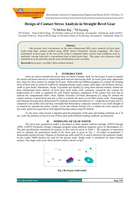
done to generate the geometrical model <strong>of</strong> the bevel gear is given <strong>in</strong> Fig. 1. 20 noded iso-parametric 3<br />
dimensional element hav<strong>in</strong>g 3 Degrees <strong>of</strong> freedom per node (solid 95) is used to descritize the geometric model.<br />
In this model 54000 element are used for the present study. S<strong>in</strong>gle tooth is considered for f<strong>in</strong>ite element<br />
analysis. The s<strong>in</strong>gle tooth sector f<strong>in</strong>ite element model is shown <strong>in</strong> fig.2<br />
Fig 1 <strong>Bevel</strong> gear tooth model<br />
www.<strong>ijcer</strong>onl<strong>in</strong>e.com ||April||2013|| Page 145
III. <strong>Bevel</strong> gear specification [4]<br />
Table 1<br />
S.NO PARAMETERS VALUE<br />
1 Pressure angle, α 20º<br />
2 Shaft angle, β 90<br />
3 Module(mm) 4<br />
4 Addendum(mm) 5.38<br />
5 Dedendum(mm) 3.37<br />
6 Rim<br />
18.8<br />
thickness(mm)<br />
7 Number <strong>of</strong> teeth 24<br />
8 Face width(mm) 20<br />
9 Cone<br />
107.33<br />
distance(mm)<br />
10 Pitch radius 48<br />
(mm)<br />
11 Semi cone angle, 26 º.34’<br />
δ<br />
12 Root fillet Trochoid<br />
13 Material C45Steel<br />
14 Poisson ratio 0.3<br />
15 Young’s<br />
Modulus<br />
2.01e5N/mm 2<br />
<strong>Design</strong> Of <strong>Contact</strong> <strong>Stress</strong> <strong>Analysis</strong>…<br />
Fig 2 Meshed tooth model (Number <strong>of</strong> elements: 54000)<br />
III. BOUNDARY CONDITIONS FOR APPLYING LOAD<br />
The nodes at the <strong>in</strong>ner radius <strong>of</strong> the rim are constra<strong>in</strong>ed <strong>in</strong> all directions and nodes <strong>in</strong> the side face <strong>of</strong><br />
rim are constra<strong>in</strong>ed <strong>in</strong> the direction perpendicular to the surface area. A study has been made for two different<br />
load<strong>in</strong>g conditions. They are uniform l<strong>in</strong>ear distributed load, and pitch po<strong>in</strong>t load at pitch po<strong>in</strong>t. The face width<br />
<strong>of</strong> the bevel gear tooth has divided <strong>in</strong>to 31 nodes for apply<strong>in</strong>g load and to evaluate.In our work, the total<br />
resultant force for apply<strong>in</strong>g load <strong>in</strong> gear is 1651N from [4]. In bevel gear, resultant tooth force Fn is applied <strong>in</strong><br />
tangentially (torque produc<strong>in</strong>g), radially (separat<strong>in</strong>g), and axially (thrust) components to the pitch po<strong>in</strong>t <strong>of</strong> gear,<br />
is designated Ft, Fr and Fa, respectively shown <strong>in</strong> figure-3.<br />
Fig 3 <strong>Gear</strong> tooth forces<br />
IV. PITCH POINT LOAD<br />
In this load<strong>in</strong>g conditions Fn is resolved <strong>in</strong> to Ft, Fr and Fa and they are applied to the pitch po<strong>in</strong>t. The<br />
pitch po<strong>in</strong>t load <strong>in</strong> bevel gear tooth shown <strong>in</strong> figure-4. The loads are calculated us<strong>in</strong>g the expressions,<br />
Fn = Ft/cosα, Fr = F t tan α cosδ, Fa = F t tan α s<strong>in</strong>δ<br />
Where,<br />
Ft = Tangential force<br />
α = Pressure angle<br />
δ = Semi cone angle<br />
www.<strong>ijcer</strong>onl<strong>in</strong>e.com ||April||2013|| Page 146
<strong>Design</strong> Of <strong>Contact</strong> <strong>Stress</strong> <strong>Analysis</strong>…<br />
V. UNIFORMLY DISTRIBUTED LINEAR LOAD<br />
The load uniformly distributed along the face width on pitch l<strong>in</strong>e and it is shown <strong>in</strong> figure.5<br />
Fig 4 Pitch po<strong>in</strong>t load<br />
Fig 5 Uniform distributed<br />
L<strong>in</strong>ear load<br />
VI. EVALUTION OF STRESS AT THE ROOT FILLET<br />
The tooth behavior is studied for the given load and the maximum pr<strong>in</strong>ciple stress is illustrated <strong>in</strong> Fig<br />
6,7, for various load<strong>in</strong>g conditions. The maximum fillet stress calculated as per AGMA standard for the given<br />
load is only 52.43N/mm².<br />
120<br />
Root stress(N/mm 2 )<br />
100<br />
80<br />
60<br />
40<br />
20<br />
0<br />
0 10 20 30<br />
Face width (mm)<br />
Pitch po<strong>in</strong>t load<br />
Uniform<br />
distributed l<strong>in</strong>ear<br />
load<br />
Figure 6 Root stress’s at drive side along face width<br />
It is observed from the graph that for the pitch po<strong>in</strong>t load the fillet stress at the drive side is gradually<br />
<strong>in</strong>creas<strong>in</strong>g from toe side to mid section and similar manner from the mid section to heel side it is gradually<br />
reduc<strong>in</strong>g. When the load is uniformly distributed along the entire pitch l<strong>in</strong>e, the stress value is more nearer to toe<br />
side when compare to that <strong>of</strong> heel side.<br />
Figure 7 Root stress’s at non drive side along face width<br />
www.<strong>ijcer</strong>onl<strong>in</strong>e.com ||April||2013|| Page 147
<strong>Design</strong> Of <strong>Contact</strong> <strong>Stress</strong> <strong>Analysis</strong>…<br />
It is observed from the graph that for the pitch po<strong>in</strong>t load the fillet stress at the non-drive side is<br />
gradually decreas<strong>in</strong>g from toe side to mid section and similar manner from the mid section to heel side it is<br />
gradually <strong>in</strong>creas<strong>in</strong>g. When the load is uniformly distributed along the entire pitch l<strong>in</strong>e, the stress value is more<br />
nearer to toe side when compare to that <strong>of</strong> heel side<br />
VII. CONCLUSION<br />
3D bevel gear model at f<strong>in</strong>ite element model us<strong>in</strong>g ANSYS has been generated and analyzed <strong>in</strong> this<br />
work. The <strong>in</strong>fluence load on the root stress <strong>in</strong> straight bevel gear is evaluated for two different conditions. The<br />
stress <strong>in</strong> gear tooth is high at toe side and comparatively low at heel side.<br />
REFERENCE<br />
[1] Buck<strong>in</strong>gham .E, Analytical mechanics <strong>of</strong> gears, Dover pubns, 1988.<br />
[2] S. J. Nalluveettil and G. Muthuveerappan,”F<strong>in</strong>ite element model<strong>in</strong>g and analysis <strong>of</strong> a straight bevel gear tooth”, computers &<br />
structures, vol. 48, no.4, pp.739-744, 1993.<br />
[3] V. Ramamurti, Nayak h. Vijayendra and c. Sujatha.”Static and dynamic analysis <strong>of</strong> spur and bevel gears us<strong>in</strong>g fem,”Mech mach.<br />
Theory vol.33, no.8, pp.1177-1193, 1998.<br />
[4] SS.Vijayarangan and N.Ganesan,” Static stress analysis <strong>of</strong> a composite bevel gear us<strong>in</strong>g a three dimensional f<strong>in</strong>ite element<br />
method”, computers & Structures, vol. 51, No. 6, pp, 771-783, 1994.<br />
[5] A. Nour, T. Djedid, Y. Chevalier, M.O. Si-Chaïb, and M.S.Bouamrene,” <strong>Stress</strong> analysis <strong>of</strong> spiral bevel gears us<strong>in</strong>g f<strong>in</strong>ite element<br />
method”<br />
[6] Faydor L. Litv<strong>in</strong> and Alfonso fuentes,”design and stress analysis <strong>of</strong> low-noise adjusted bear<strong>in</strong>g contact spiral bevel gears”,<br />
Nasa/Cr, 2002<br />
www.<strong>ijcer</strong>onl<strong>in</strong>e.com ||April||2013|| Page 148