Service Information Letter A-119 - Hartzell Engine Technologies
Service Information Letter A-119 - Hartzell Engine Technologies
Service Information Letter A-119 - Hartzell Engine Technologies

You also want an ePaper? Increase the reach of your titles
YUMPU automatically turns print PDFs into web optimized ePapers that Google loves.
<strong>Service</strong><br />
<strong>Information</strong> <strong>Letter</strong><br />
The technical content of this letter is FAA Approved<br />
<strong>Letter</strong> No. A-<strong>119</strong> Issue Date: Mar. 24, 2006<br />
Voltage Regulator Adjustment - VR515GA<br />
INTRODUCTION:<br />
Recently there have been several questions regarding access and adjustment of the Kelly Aerospace Power<br />
Systems (Electrodelta) voltage regulator part number VR515GA & VR515GA-1. The three primary inquiries<br />
were how to properly access the internal adjustment potentiometer, the proper range of adjustment, and<br />
whether adjustment voids the warranty.<br />
This <strong>Service</strong> <strong>Information</strong> letter is intended to provide answers to the above questions and to illustrate and<br />
elaborate the adjustment procedure..<br />
COMPLIANCE:<br />
At the discretion of the owner/operator or the facility performing maintenance any time a voltage<br />
regulator adjustment is required.<br />
EFFECTIVITY:<br />
Any aircraft or rotorcraft utilizing a Kelly Aerospace Power Systems (Electrodelta) voltage regulator part<br />
number VR515GA or VR515GA-1. (Both regulators are the same except for a change in the connector.)<br />
PROCEDURE:<br />
Voltage Regulator removed from Aircraft:<br />
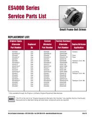
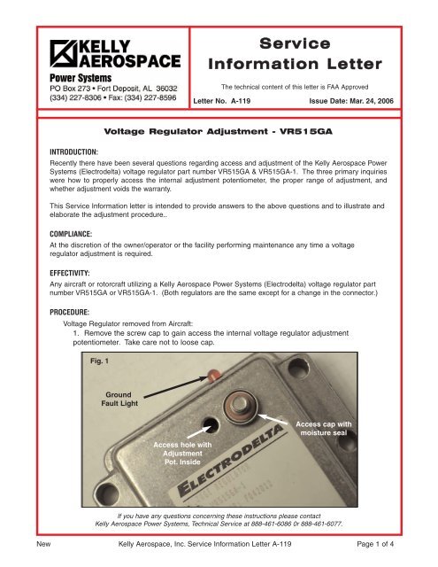
1. Remove the screw cap to gain access the internal voltage regulator adjustment<br />
potentiometer. Take care not to loose cap.<br />
Fig. 1<br />
Ground<br />
Fault Light<br />
Access hole with<br />
Adjustment<br />
Pot. Inside<br />
Access cap with<br />
moisture seal<br />
If you have any questions concerning these instructions please contact<br />
Kelly Aerospace Power Systems, Technical <strong>Service</strong> at 888-461-6086 0r 888-461-6077.<br />
New Kelly Aerospace, Inc. <strong>Service</strong> <strong>Information</strong> <strong>Letter</strong> A-<strong>119</strong> Page 1 of 4
PROCEDURE: (cont’d)<br />
Voltage Regulator Removed from aircraft: (cont’d)<br />
2. Assemble the test set up (harness) as shown in Figure 2. Use 20 to 22 gauge wire, common<br />
28v rated switch and common 28v lamps or LEDs. Use any appropriately sized male or female<br />
pin to connect to the voltage regulator connector terminals. Be sure to insulate test connections<br />
enough to avoid touching adjacent terminals.<br />
3. Attach an adjustable DC power supply capable of 0 to 34 volts at 1.5 amps to the power<br />
input wires as shown in Fig. 2. Hook up the black ground wire coming from the box (not in the<br />
connector) to a grounding point on your test bench.<br />
4. Observe the voltage regulator specifications in Table 1 and proceed to the tests below.<br />
5. Use only a properly calibrated meter for all measurements which has an error tolerance no<br />
greater than 1/2% of full scale.<br />
6. Use a non-metallic, flat blade, miniature screw driver for adjustments. Adjustment pot is<br />
a 360˚ pot. Do not force past limit as damage will occur.<br />
Pin No. Color Usage<br />
1 Blue Field<br />
2 Orange Sense<br />
3 Red Power<br />
4 Yellow Low Volt<br />
5 Black Ground<br />
6 White Over Volt<br />
Box Black Box Gnd<br />
Fig. 2 - Test Set Up<br />
Table 1 - Specifications<br />
Voltage Setting<br />
28.7 volts +/ - .05 volts<br />
Voltage Regulation Window<br />
.25 volt to 1.00 volt width (not a limit)<br />
28.25 v to 28.75 Midpoint (not a limit)<br />
Field Current<br />
4.0 amps continuous<br />
Over Voltage Trigger Point<br />
32.0 volts to 33.4 volts DC<br />
Low Voltage Setting<br />
Remains at or below 24 volts (Low volt lite on)<br />
Remains at or above 25 volts (Low volt lite off)<br />
New Kelly Aerospace, Inc. <strong>Service</strong> <strong>Information</strong> <strong>Letter</strong> A-<strong>119</strong> Page 2 of 4
Voltage Regulator Test and Adjustment (Removed from aircraft):<br />
CAUTION:<br />
WHILE PERFORMING THESE TESTS, DO NOT CONNECT OR<br />
DISCONNECT THE UNIT UNDER TEST WITHOUT FIRST<br />
TURNING OFF THE POWER SUPPLY. DAMAGE MAY RESULT TO<br />
THE VOLTAGE REGULATOR OR POWER SUPPLY.<br />
1. Voltage Regulator: Set Main Power Supply to 28.8 VDC. Adjust until the field indicator light<br />
is approximately half illuminated. Adjust input voltage upward until the field indicator light just goes<br />
OUT. This should be at approximately 30 volts. Readjust input voltage downward until the field<br />
indicator light just goes to full ON. This should be at approximately 28 volts. This completes the<br />
check out of the voltage regulation portion.<br />
2. Reset: Momentarily turn the alternator control switch OFF then ON again. The field indicator<br />
light shall illuminate indicating a reset. Use this procedure for reset whenever necessary.<br />
3. Overvoltage: With input power supply set to 28.8 VDC, adjust it slowly up to 31.0 volts. The<br />
field indicator light shall be OFF. Wait 10 seconds. and reduce input voltage to 28.8 volts. The field<br />
indicator light shall go back ON indicating the unit did not trip.<br />
4. GFP and Overvoltage: Raise input voltage to 33.4 volts. The field indicator light shall go OFF<br />
and both the ground fault protection (GFP) and overvoltage (OV) lights shall illuminate. Wait five<br />
seconds, reduce main supply voltage to 28.8 volts. The field indicator light shall remain OFF and<br />
GFP and OV lights shall remain ON signifying trip. Reset. Note the GFP light is an LED on the box.<br />
5. Low Voltage Indication: With input power supply set to 28.8 VDC, observe the Low Voltage<br />
(LV) indicator light. It should be OUT. Reduce input voltage to 24 volts. The LV light shall go ON.<br />
Return input voltage slowly back to 28.8 Volts. the LV light shall go OUT at approximately 26.5 Volts.<br />
This completes check out of the Low Voltage function.<br />
6. Output Ground Fault Protection (GFP): With the main power supply set to 28.8 VDC, (field<br />
indicator light half illuminated) while monitoring the current output meter of the power supply,<br />
momentarily apply a short circuit from ground to the field output lead, (Blue). The field indicator light<br />
shall go OUT with no continuous indication of over current on the meter and the GFP indicator light<br />
on the unit shall illuminate. Remove the short. The unit shall remain OFF with the GFP indicator<br />
light illuminated. Reset. GFP, the indicator light shall go out and the field indicator light shall come<br />
back ON at half brilliance as before the test. This completes check out of the GFP function.<br />
7. Inspect moisture seal on the screw cap and replace if necessary. Install the screw cap.<br />
8. If the unit being tested has been removed from an aircraft or rotorcraft and is being reinstalled,<br />
to be returned to service, a logbook entry of compliance with this service information letter is<br />
required.<br />
Voltage Regulator Adjustment (Installed in aircraft/rotorcraft):<br />
WARNING:<br />
SERIOUS INJURY CAN OCCUR DURING OPERATION OF<br />
PROPELLERS AND ROTOR BLADES. BE SURE THAT ALL<br />
PRECAUTIONS ARE TAKEN TO MAKE THE PROCEDURE SAFE.<br />
1. Gain access to the voltage regulator. Refer to the aircraft/rotorcraft manufacturers service<br />
and maintenance manuals.<br />
2. Remove the screw cap to gain access the internal voltage regulator adjustment<br />
potentiometer. Take care not to loose cap.<br />
3. With the aircraft/rotorcraft running attach a voltmeter to measure the aircraft/rotorcraft main<br />
DC bus voltage. (See Fig. 3.)<br />
New Kelly Aerospace, Inc. <strong>Service</strong> <strong>Information</strong> <strong>Letter</strong> A-<strong>119</strong> Page 3 of 4
Voltage Regulator Adjustment (Installed in aircraft/rotorcraft): (cont’d)<br />
4. Use a non-metallic, flat blade, miniature screw driver for adjustments. Adjustment pot is<br />
a 360˚ pot. Do not force past limit as damage will occur.<br />
5. Unless otherwise stated in the aircraft/rotorcraft manufacturers service and maintenance<br />
manuals, adjust the voltage regulator to 28.8 volts +/ - .05 volt. If regulation cannot be<br />
achieved, investigate cause starting with the ships systems (wiring, battery, and alternator). If<br />
ships system check OK, remove voltage regulator and perform the tests above or replace the<br />
voltage regulator.<br />
6. Upon successful completion of the adjustment procedure, inspect moisture seal on the<br />
screw cap and replace if necessary. Install the screw cap.and prepare the aircraft/rotorcraft for<br />
return to service.<br />
7. Make a logbook entry of compliance with this service information letter.<br />
Fig. 3 - Simplified<br />
Aircraft/rotorcraft Installation<br />
Pin No. Color Usage<br />
1 Blue Field<br />
2 Orange Sense<br />
3 Red Power<br />
4 Yellow Low Volt<br />
5 Black Ground<br />
6 White Over Volt<br />
Box Black Box Gnd<br />
Fig. 4<br />
Warranty Note:<br />
Adjustments to the voltage regulator<br />
(VR515GA or VR515GA-1) are permitted<br />
without voiding the Kelly Aerospace Power<br />
Systems Limited Warranty provided the<br />
“warranty seal” as shown in Fig.4 has not<br />
been broken or tampered with.<br />
New Kelly Aerospace, Inc. <strong>Service</strong> <strong>Information</strong> <strong>Letter</strong> A-<strong>119</strong> Page 4 of 4