bbhandbookchassis64 73 - Thomson Caravans
bbhandbookchassis64 73 - Thomson Caravans
bbhandbookchassis64 73 - Thomson Caravans

Create successful ePaper yourself
Turn your PDF publications into a flip-book with our unique Google optimized e-Paper software.
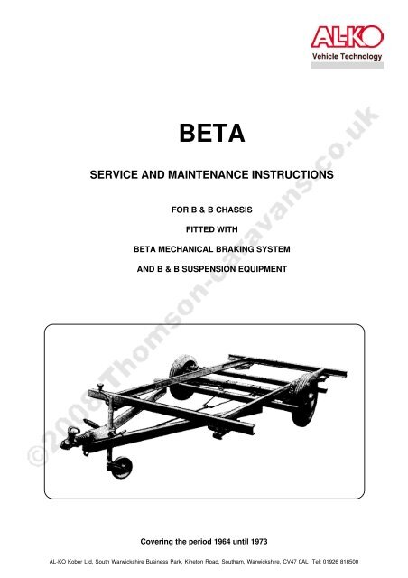
BETA<br />
SERVICE AND MAINTENANCE INSTRUCTIONS<br />
FOR B & B CHASSIS<br />
FITTED WITH<br />
BETA MECHANICAL BRAKING SYSTEM<br />
AND B & B SUSPENSION EQUIPMENT<br />
Covering the period 1964 until 19<strong>73</strong><br />
AL-KO Kober Ltd, South Warwickshire Business Park, Kineton Road, Southam, Warwickshire, CV47 0AL Tel: 01926 818500
Axle Equipment<br />
Adjustment - Lockheed 7" brakes<br />
1 Jack up axle raising<br />
wheel clear of ground.<br />
2 Remove road wheel.<br />
3 Revolve brake drum until adjustment<br />
hole is in line with toothed<br />
adjustment wheel. Insert a<br />
cranked lever or screwdriver not<br />
exceeding 6" in length, and turn<br />
the toothed wheel in a clockwise<br />
direction relative to it’s fixing,<br />
until one side bears against the<br />
drum. Then continue turning until<br />
both shoes bear hard. Back off<br />
the adjustment the least possible<br />
amount until the wheel can<br />
be revolved. This brake is then<br />
correctly adjusted. Carry out<br />
same procedure on opposite<br />
wheel.<br />
4 Replace road wheel, making<br />
sure to correctly tighten wheel<br />
nuts (Torque to 65lbs/ft in sequence<br />
- i.e. North, South, East,<br />
West - NEVER clockwise or anticlockwise.<br />
With 5 stud wheels<br />
Torque to 65lbs/ft in opposites.<br />
5 Carry out same procedure on<br />
opposite wheel.<br />
Adjustment - Lockheed 8", 9" and<br />
10" brakes<br />
1 Jack up axle, raising wheel<br />
clear of ground.<br />
2 Remove road wheel.<br />
3 Revolve brake drum until adjustment<br />
hole is in line with screwdriver<br />
slot-headed adjustment<br />
screw. Then with a screwdriver<br />
rotate the adjustment screw in a<br />
clockwise direction as far as it<br />
will go and then return it “two<br />
clicks” ensuring at the same time<br />
that brake drum revolves freely.<br />
This brake is then correctly adjusted.<br />
4 Replace road wheel, making sure<br />
to correctly tighten wheel nuts<br />
(Torque to 65lbs/ft in sequence -<br />
i.e. North, South, East, West -<br />
NEVER clockwise or anti-clockwise.<br />
With 5 stud wheels Torque<br />
to 65lbs/ft in opposites.<br />
5 Carry out same procedure on<br />
opposite wheel.<br />
Adjustment - Girling 12" brake<br />
1 Jack up axle raising wheel<br />
clear of ground.<br />
2 The square headed adjustment<br />
screw is located on the back of<br />
the brake back plate. This must<br />
be turned in a clockwise direction<br />
as far as it will go and then<br />
returning only sufficient to allow<br />
wheels to revolve freely. This<br />
brake is then correctly adjusted.<br />
3 Replace road wheel, making sure<br />
to correctly tighten wheel nuts<br />
(Torque to 65lbs/ft in sequence -<br />
i.e. North, South, East, West -<br />
NEVER clockwise or anti-clockwise.<br />
With 5 stud wheels Torque<br />
to 65lbs/ft in opposites.<br />
4 Carry out same procedure on<br />
opposite wheel.
SYMPTOM POSSIBLE CAUSE REMEDY<br />
Brake drag with overheating<br />
(Note: Heat is always<br />
generated under normal braking.<br />
These possible causes and<br />
actions are for overheating when<br />
not actually braking)<br />
Brake Inefficient<br />
1 Handbrake incorrectly ad<br />
justed.<br />
2 Pull rod not returning<br />
freely to the “OFF” posi<br />
tion.<br />
3 Weak or broken pull off<br />
springs.<br />
4 Expander assembly<br />
binding or seized.<br />
5 Shoes incorrectly adjusted.<br />
1 Glazed brake lining<br />
surfaces.<br />
2 Scored or rusty drum surface.<br />
3 Overrun assembly pull rod out<br />
of adjustment.<br />
4 Shoes incorrectly adjusted.<br />
Adjust handbrake according to<br />
recommendations.<br />
Check tension of pull rod, pull off<br />
springs. Check expander operation.<br />
See “possible cause”<br />
number 4.<br />
Examine condition of pull off<br />
spring over stretching or heat<br />
affected. Replace as necessary.<br />
Dismantle expander, lubricate<br />
and rebuild ensure expander is<br />
free to slide in the backplate slot.<br />
Carry out correct adjustment<br />
procedure.<br />
Clean glaze from shoe lining<br />
surface with dampened smooth<br />
emery paper and produce matt<br />
finish.<br />
Examine condition of brake drum<br />
surface light rusting may be<br />
removed with smooth emery<br />
paper. Otherwise if rusting or<br />
scoring is severe, renew drum.<br />
Carry out adjustment as recommended.<br />
Carry out correct brake adjustment<br />
procedure.<br />
ASBESTOS BRAKE LININGS<br />
Care should be taken in handling brake shoes which contain asbestos and the relevant<br />
regulations adhered to.
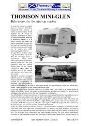
“BETA” OVERRUN ASSEMBLY<br />
Hand-Brake<br />
Greasing Points<br />
Reverse<br />
Lever<br />
Safety<br />
Catch<br />
Over-Run<br />
Lever<br />
Damper Bracket<br />
Break-Away Chain<br />
Damper<br />
Ratchet Plate<br />
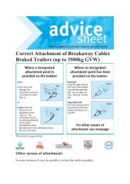
INDEPENDENT SUSPENSION CHASSIS<br />
Brake<br />
Suspension Spring<br />
Brake Linkage<br />
Hand-Brake<br />
50mm<br />
Coupling<br />
Head<br />
Breakaway<br />
Chain Guide<br />
Jockey Wheel Clamp<br />
Corner Legs<br />
Telescopic<br />
Jockey Wheel
PART PART NO. DESCRIPTION OF PART QTY<br />
12 CC 2194 Retaining Washer 1<br />
13 CC 2118 Split Ring 2<br />
14 04-22-092-100 Hydraulic Damper (Stabilus) 1<br />
15 317 UNF 3/8" UNF x 2 1/4" Hex Bolt 1<br />
16 CC 2293 Damper Bracket 1<br />
17 CC 9308 Split Ring 2<br />
18 CC 535 Rubber Washer 1<br />
19 3008 UNF 3/8" UNF Binx Nut 1<br />
20 CC 2201 Assembled Head and Shaft 1<br />
21 CC 1454 Mills Pin 1<br />
22 M.S. Pin<br />
23 CC 1470A Safety Catch Assembly 1<br />
24 Safety Catch Bolt M10 x 50<br />
25 CC 12610 50mm Plunger 1<br />
26 CC 1265A Outer Spring 1<br />
27 C 1266A Middle Spring 1<br />
28 C 1653 Inner Spring 1<br />
29 CC 1472A Spring 1<br />
30 CC 1471 Nylon Plunger 1<br />
31 CC 2108 Release Handle 1*<br />
32 Single Coil Washer M10 S.C. 1<br />
33 Full Nut M10 1<br />
34 CC 2760 PVC Boot 1<br />
35 SP 182 Grease Nipple 2<br />
36 Fixing Bolts, Spring Washer & Nut 2*<br />
37 CC 2096 Body Casting 1*<br />
38 Fixing Bolt, Spring Washer & Nut 2*<br />
39 SP245 3/16" Washer (was SP481) 2*<br />
40 SP 482 3/16" x 3/8" Screw 2*<br />
41 300L UNF 3/8" UNF Locknut 2<br />
42 2305 SC 3/8" Single Coil Washer 1<br />
43 2305 3/8" MS Washer 1<br />
44 CC 2485 Solenoid Cover Plate 1*<br />
45 CC 2132 1/4" UNF x 3/8" Socket Set Screw 1<br />
46 CC 2353 MS Pivot Tube 1<br />
47 CC 2120 Collar 1<br />
48 CC 2102 Overrun Brake Lever 1<br />
49 CC 2203 Handbrake Sub-Assembly 1<br />
50 CC 2548 Drive-in Rivet 2*<br />
51 CC 2124A Black Plastic Grip 1<br />
52 CC 21288 Release Knob 1<br />
53 CC 4147 Dirt Shroud (Stabilus) 1*<br />
54 CC 3506M Locking Handle (Jockey Wheel) 1<br />
55 CC 914 Pressure Pad (Light) (Not Shown) 1<br />
56 CC 715 Pressure Pad (Heavy) (Not Shown) 1<br />
* Check for availability
INDEPENDENT SUSPENSION<br />
PART PART NO. DESCRIPTION OF PART QTY<br />
Brake Rod - 3/8" MS<br />
1 CC 2782 Fork End 1*<br />
2 CC 2884 Rod/Fork Assembly 2<br />
3 CC 2884<br />
CC 1749 Brake Return Spring 2<br />
4 CC 1787 Tab 2<br />
CC 2049 Brake Rod Stop/Bolt Assembly 2<br />
5 356159 Damper Assembly (was SP 3608) 2<br />
6 Suspension Spring 2<br />
CC 1857<br />
5" (Blue)<br />
CC 1746<br />
6" (Black)<br />
CC 1747<br />
6" (Red)<br />
CC 1927<br />
6" (Brown)<br />
CC 2970<br />
6" (Purple)<br />
7 CC 2660 Spring Compression Bolt 2<br />
8 356193 Spring Place (was CC 1779) 2<br />
9 Nut 5/8" B.S.F. 2<br />
10 CC 3887 Rebound Stop 5" Spring 2<br />
356162 Rebound Stop 6" Spring (was CC 3857) 2<br />
11 CC 2242L Swinging Arm Assembly MK III LH (8" Drum) 1<br />
CC 2242R Swinging Arm Assembly MK III RH (8" Drum) 1<br />
CC 1698L Swinging Arm Assembly MK II LH (8" Drum) 1<br />
CC 1698R Swinging Arm Assembly MK II RH (8" Drum) 1<br />
12 356157 Nylon Bush (was CC 2326) 8<br />
13 356158 Sleeve (was CC 2376) 4<br />
14 CC 2882 Sleeve, Bolt, Nut, Tab Assembly 4*<br />
15 CC 2883 Brake Rod/Fork Assembly 2<br />
16 CC 3529 Compensator c/w Grease Nipple 2*<br />
17 701535 Compensator Pivot Bolt c/w Nut 2<br />
18 377433 Damper - Top Rubbers / Washer 2<br />
19 377434 Damper - Bottom Rubbers 2<br />
20 556295 Heavy Duty Washer 2<br />
* Check for availability
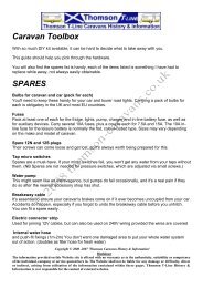
CORNER LEGS (STEADIES)<br />
12a<br />
9<br />
10<br />
5<br />
CC3560<br />
6<br />
7<br />
13a<br />
5<br />
6<br />
2<br />
11<br />
2<br />
12<br />
9<br />
10<br />
6<br />
5<br />
7<br />
7<br />
3<br />
8a<br />
13<br />
4<br />
5<br />
6<br />
2<br />
15<br />
2<br />
7<br />
3<br />
8<br />
CC2330<br />
4<br />
PART PART NO. DESCRIPTION OF PART QTY<br />
2/3 319 UNF/300B 2 1/2" x 3/8" UNF Bolt and Binx Nut 1<br />
2/4 315 UNF/300B 2" x 3/8" UNF Bolt and Binx Nut 1<br />
5/6 CC 602/CC 2762 Circlip and Pivot Pin 1<br />
7 CC 2335 Side Arm 1<br />
8 CC 2333 Leg (2330 Corner Steady) 1*<br />
8a CC 2337 Leg (CC 3560 Corner Steady) 1<br />
9 CC 591 Mills Pin 1<br />
10 CC 185 Washer 1<br />
11 CC 4693 Nut 1<br />
12 CC 2332 Screw (length 15 1/2") (CC 2330 Corner Steady) 1<br />
12a CC 651 Screw (length 17 3/4") (CC 3560 Corner Steady) 1<br />
13 CC 2331 Base Plate (CC 2330 Corner Steady) -*<br />
13a CC 3893 Base Plate (CC 3560 Corner Steady) -*<br />
15 CC 2338 Wing Nut 1*<br />
* Check for availability
Mechanical Brake for <strong>Caravans</strong> and Trailers<br />
4615-032 RH 4615-036 RH 4615-038 RH 4622-240 RH<br />
4615-033 LH 4615-037 LH 4615-039 LH 4622-241 LH<br />
8 x 1 1/2ins 8 x 1 1/2ins 9 x 1 1/2ins 9 x 1 3/4ins<br />
Ref Description 203 x 38mm 203 x 38mm 203 x 38mm 229 x 44mm<br />
1 Micram Adjustor 25254 25254 + See below 25254<br />
2 Mask 25253 25253 25253 25253<br />
3 Body 107282 RH 32038 32038 32038<br />
4 Inner Lever 3264-231 3624-231 3624-231 3624-231<br />
5 Pin 3414-254 3414-254 3414-254 3414-254<br />
6 Outer Lever (2) 115618 115618 115618 115618<br />
7 Pin 3414-253 3414-253 3414-253 3414-253<br />
8 Eye End 3761-420 4114055* 3761-420 3761-420<br />
9 Boot 32324 32324 32324 32324<br />
10 Pull off Spring 89726 89726 89726 33061<br />
11 Back plate 4562-770 RH 4562-038 RH 4562-038 RH 4564-102 RH<br />
4562-771 LH 4562-039 LH 4562-039 LH 4564-103 LH<br />
12 Nut K24001 K18609 K18609 K18609<br />
13 Spring Washer K19207 K19208 K19208 K19208<br />
14 Abutment 25294 25294 25294 25294<br />
15 Tension Spring 83462 25553 25553 25472<br />
16 Brake Shoes * * * *<br />
17 Expander SSB75647 SSB75648 SSB75644 SSB75644<br />
18 Pin 3443-232 - 3443-232 3443-232<br />
* Refer to Application Lists S101 or S825 + NB Ref 4615-038/9<br />
ñ Includes Pin Ref 18 Micram Part No. LB 04 HL031A Shoe S/A - 4523-092<br />
4622-242 RH 4622-244 RH 4632-028 RH 4632-286 RH<br />
4622-243 LH 4622-245 LH 4622-245 LH 4632-287 LH<br />
9 x 1 3/4ins 9 x 1 3/4ins 10 x 1 3/4ins 10 x 1 3/4ins<br />
Ref Description 229 x 44 mm 229 x 44mm 254 x 44mm 254 x 44mm<br />
1 Micram Adjustor 34137 25254 25254 25254<br />
2 Mask 25253 25253 25253 25253<br />
3 Body 4151-619 32038 88645 88645<br />
4 Inner Lever 3624-231 3624-231 88656 88645<br />
5 Pin 3414-254 3414-254 3414-252 88653<br />
6 Outer Lever (2) 115618 115618 88650 88650<br />
7 Pin 3414-253 3414-253 3414-255 91139<br />
8 Eye End 3761-420 3761-420 3761-422 104646<br />
9 Boot 32324 32324 32324 32324<br />
10 Pull off Spring 33061 33061 95393 95394<br />
11 Back plate 4564-102 RH 4564-102 RH 4586-674 RH 102382 RH<br />
4564-103 LH 4564-103 LH 4566-675 LH 102383 LH<br />
12 Nut K18609 K18609 K18609 K18609<br />
13 Spring Washer K19208 K19208 K19208 K19208<br />
14 Abutment 25294 25294 25294 25294<br />
15 Tension Spring 25472 25472 89963 25<strong>73</strong>8<br />
16 Brake Shoes * * * *<br />
17 Expander SSB75646 SSB75644 SSB75645 SSB75645<br />
18 Pin 3443-232 3443-232 3443-232 -<br />
* Refer to Application Lists S101 or S825 + NB Ref 4615-038/9<br />
ñ Includes Pin Ref 18 Micram Part No. LB 04 HL031A Shoe S/A - 4523-092