Download the Rubbery Owen Maintenance Manual in PDF Format
Download the Rubbery Owen Maintenance Manual in PDF Format
Download the Rubbery Owen Maintenance Manual in PDF Format
- No tags were found...

You also want an ePaper? Increase the reach of your titles
YUMPU automatically turns print PDFs into web optimized ePapers that Google loves.
INDEXPageGENERAL INSTRUCTIONS 2ASSEMBLY OF HUBS FITTED WITH TAPERROLLER BEARINGSPreparation 2Fitt<strong>in</strong>g 3Adjustment 3BRAKESAxles fitted with Girl<strong>in</strong>g brakes 4Axles fitted with Lockheed brakes 4Brake l<strong>in</strong><strong>in</strong>gs 4TORSION BAR AXLESReplacement 5<strong>Ma<strong>in</strong>tenance</strong> 5Boat trailer axles 5ELECTRIC BRAKE AXLESInitial adjustment6CHECKING THE ELECTRICAL CIRCUIT6CHECKING THE ELECTRICAL COMPONENTS61. Automatic controller bench check 62. Stop light switch 73. Hydraulic cyl<strong>in</strong>der leakage 74. Magnet assembly 75. Magnet bench check 8CHECKING THE MECHANICALCOMPONENTS1. Bear<strong>in</strong>gs and seals 82. Armature plates 83. Brake adjustment 8BOAT TRAILER ELECTRIC BRAKES9SMOOTHA-HITCH 10Electrically operated revers<strong>in</strong>g mechanism 10CHASSIS 10
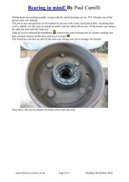
GENERAL INSTRUCTIONSTo ensure satisfactory operation of all work<strong>in</strong>g parts <strong>the</strong>follow<strong>in</strong>g <strong>in</strong>structions should be carried out at <strong>in</strong>tervals of3,000 miles or prior to <strong>the</strong> trailer rema<strong>in</strong><strong>in</strong>g stationary forperiods exceed<strong>in</strong>g six months unless o<strong>the</strong>rwise stated.ASSEMBLY OF HUBS FITTED WITH TAPER ROLLERBEARINGSPREPARATION(a) The hub or <strong>the</strong> hub portion of a comb<strong>in</strong>ed brakedrum and hub will have <strong>the</strong> taper roller bear<strong>in</strong>g cupssecurely and accurately <strong>in</strong> position.WHEELSCheck tightness of wheel nuts.Check tyre pressures weekly and ma<strong>in</strong>ta<strong>in</strong> <strong>the</strong> pressuresat maker’s recommendation. Any unusual pressure lossshould be <strong>in</strong>vestigated as under-<strong>in</strong>flation causes rapidtyre wear and may damage <strong>the</strong> cords of <strong>the</strong> fabric.(b) The <strong>in</strong>terior of <strong>the</strong> hubsmust be clean beforeliberally pack<strong>in</strong>g with goodquality high melt<strong>in</strong>g po<strong>in</strong>ttaper roller bear<strong>in</strong>g greasei.e. Ret<strong>in</strong>ax ‘A’, Nulsec ‘L’ orequivalent.HUBS(c) The operat<strong>in</strong>g diametersof <strong>the</strong> axle must be clean.Remove hub cap. Check taper roller bear<strong>in</strong>g adjustmentby rock<strong>in</strong>g hub. There should be little or no perceptibleshake but should be complete freedom to rotate. (Forlubrication of taper roller bear<strong>in</strong>gs see “Assembly ofhubs fitted with taper roller bear<strong>in</strong>gs”).(d) The taper roller bear<strong>in</strong>gcones must be greased as(b) ensur<strong>in</strong>g that <strong>the</strong>grease penetrates <strong>in</strong>side<strong>the</strong> roller cage, between<strong>the</strong> rollers and <strong>the</strong> cones,2
ADJUSTMENTFITTING(e) The <strong>in</strong>ner bear<strong>in</strong>gcone must be placed<strong>in</strong>side <strong>the</strong> <strong>in</strong>ner bear<strong>in</strong>gcup and <strong>the</strong> grease sealplaced <strong>in</strong>to position <strong>in</strong>side<strong>the</strong> hub.(g) The slotted nut must <strong>the</strong>n be tightened us<strong>in</strong>g aspanner.(f) The hub subassemblymust <strong>the</strong>n becarefully positioned on<strong>the</strong> axle and supportedsquarely until <strong>the</strong> outerbear<strong>in</strong>g cone has beenplaced <strong>in</strong> position <strong>in</strong>sideits cup, <strong>the</strong> washerplaced aga<strong>in</strong>st it, and <strong>the</strong>slotted nut handtightened aga<strong>in</strong>st <strong>the</strong>washer.If this procedure is notadhered to <strong>the</strong> greaseseal could be damaged.‘IIMPORTANT:Whilst this is be<strong>in</strong>g done <strong>the</strong> hub must be rotated byhand until it is locked by <strong>the</strong> tighten<strong>in</strong>g of <strong>the</strong> nut acuon<strong>the</strong>n slacken off <strong>the</strong> slotted nut through 120 (i.e. two fiatsI or until .003” to .007” end float is atta<strong>in</strong>ed. Periodicchecks must be made to ensure that <strong>the</strong> end float isma<strong>in</strong>ta<strong>in</strong>ed,NOTE! The hubs must not be struck with a malletThe selection of <strong>the</strong> appropriate slot to l<strong>in</strong>e up with <strong>the</strong>split p<strong>in</strong> hole must be made so that <strong>the</strong> end float isnearer to <strong>the</strong> .003” where possible. End float must neverbe less than .003” s<strong>in</strong>ce too little will pre-load <strong>the</strong>bear<strong>in</strong>gs and result <strong>in</strong> premature failure.(h) The split p<strong>in</strong> must be<strong>in</strong>serted and <strong>the</strong> outsideleg bent over as shown.The <strong>in</strong>side leg must be cutshort.3
(j) The hub cap is placed <strong>in</strong>toposition and secured by tapp<strong>in</strong>gwith a mallet.Correct sett<strong>in</strong>g of compensated brake l<strong>in</strong>kage on torsionBRAKESBefore attempt<strong>in</strong>g brake adjustment lift each wheel clear of<strong>the</strong> ground with a jack, and slacken off <strong>the</strong> hitch to brakel<strong>in</strong>kage.AXLES FITTED WITH GIRLING BRAKESAdjustment is effected by rotat<strong>in</strong>g<strong>the</strong> adjust<strong>in</strong>g screw (A) at <strong>the</strong> rearof each brake backplate <strong>in</strong> aclockwise direction until <strong>the</strong> shoesare <strong>in</strong> contact with <strong>the</strong> drums andprevent<strong>in</strong>g rotation of <strong>the</strong> hub; <strong>the</strong>screw is <strong>the</strong>n rotated three clicks<strong>in</strong> an anti-clockwise direction oruntil free rotation of wheel isobta<strong>in</strong>ed; re-set ma<strong>in</strong> brake l<strong>in</strong>kage.bar axles.Correct sett<strong>in</strong>g of compensated brake l<strong>in</strong>kage on squareAdjustment is effected by first remov<strong>in</strong>g <strong>the</strong> wheel, reveal<strong>in</strong>gAXLES FITTED WITH LOCKHEED BRAKESbeam axles.BRAKE LININGS<strong>the</strong> plastic cap <strong>in</strong> <strong>the</strong> brake drum. Remove <strong>the</strong> cap androtate <strong>the</strong> drum until <strong>the</strong> adjust<strong>in</strong>g screw appears <strong>in</strong> <strong>the</strong> hole.Us<strong>in</strong>g a screwdriver, rotate screw until shoes contact drumand prevent rotation of hub. Rotate screw <strong>in</strong> oppositedirection for three ‘clicks’, or until free rotation of <strong>the</strong> hub isobta<strong>in</strong>ed. Replace plastic cap and wheel. Re-set ma<strong>in</strong> brakel<strong>in</strong>kage.Inspect <strong>the</strong> brake l<strong>in</strong><strong>in</strong>gsfor wear, If a l<strong>in</strong><strong>in</strong>g isworn to <strong>the</strong> rivets itshould be replaced. If al<strong>in</strong><strong>in</strong>g is badlycontam<strong>in</strong>ated withgrease, oil etc., it mustbe replaced, s<strong>in</strong>cecontam<strong>in</strong>ation of thistype cannot be sanded ordissolved out.IMPORTANT. Always replacebrake l<strong>in</strong><strong>in</strong>gs <strong>in</strong>sets— on both brakes on<strong>the</strong> same axle.4
TORSION BAR AXLESREPLACEMENTTo replace a torsion bar lift <strong>the</strong> side required with a jack.Remove sw<strong>in</strong>g arm cone screw and locknut. Removebar from <strong>the</strong> sw<strong>in</strong>g arm sub-assembly. Tak<strong>in</strong>g care to placedimple for screw location <strong>in</strong> <strong>the</strong> torsion bar adjacent toscrew hole, fit new torsion bar and replace locknut andscrew, tighten<strong>in</strong>g both to torque of 55-60 lb ft. Refit sw<strong>in</strong>garm sub-assembly and replace locknut and screw,apply<strong>in</strong>g 55-60 lb. ft. torque. Reconnect brake end fitt<strong>in</strong>gand adjust as necessary. Replace wheel.MAINTENANCERemove sw<strong>in</strong>g arm sub-assembly on each side as outl<strong>in</strong>edabove.The follow<strong>in</strong>g are necessary as an anti-corrosivemeasure. Grease torsion bar and ground sleeve attachedto sw<strong>in</strong>g arm. The recommended lubricants for allapplications are Ret<strong>in</strong>ax ‘A’, Nulsec ‘L’ or equivalent.BOAT TRAILER AXLESRemove <strong>the</strong> wheel. Remove brake cable end fitt<strong>in</strong>g fromabutments on underside of axle tube.On <strong>the</strong> required side and near <strong>the</strong> centre front, slackenSpecial attention should be given to boat trailer axleswhich are subjected to immersion dur<strong>in</strong>g boat launch<strong>in</strong>gsTo ensure <strong>the</strong> satisfactory operation of all work<strong>in</strong>g parts<strong>the</strong> follow<strong>in</strong>g <strong>in</strong>structions should be carried out at <strong>in</strong>tervalsof six months or before trailer is stored.1. Carry out normal torsion bar and square beam axlema<strong>in</strong>tenance as previously stated2. Remove wheels. Remove plastic and wash out brakedrums with clean fresh water. Refit plastic caps andwheels. A short run after this operation us<strong>in</strong>g <strong>the</strong> brakes asmuch as possible will ensure thorough dry<strong>in</strong>g out forstorage.3.Remove hub caps. Inspect <strong>in</strong>ternal fitt<strong>in</strong>gs forcorrosion. Repack with grease if required. Replace hub cap.<strong>the</strong> locknut on <strong>the</strong> axle tube. Remove <strong>the</strong> cone screwand locknut.Remove sw<strong>in</strong>g arm sub-assembly and torsion bar bytapp<strong>in</strong>g with mallet <strong>the</strong> <strong>in</strong>side face of sw<strong>in</strong>g arm close to<strong>the</strong> tube.4. SPECIAL NOTE FOR CONTINUED SUBMERSION INSEA WATER.Where <strong>the</strong>re has been submersion <strong>in</strong> <strong>the</strong> sea water for periodsof more than one hour wash<strong>in</strong>g out of brakes after eachsubmersion as outl<strong>in</strong>ed <strong>in</strong> (2) is essential for cont<strong>in</strong>uedsatisfactory operation.5
ELECTRIC BRAKE AXLESINITIAL ADJUSTMENTFor controllers fitted with hydraulic plungeradjustment.Before road use <strong>the</strong> controller lever should be turned toset <strong>the</strong> adjustment <strong>in</strong> <strong>the</strong> mean position.Dur<strong>in</strong>g <strong>in</strong>itial road tests adjust <strong>the</strong> hydraulic plunger ifnecessary to give <strong>the</strong> optimum performance. Slightvariations may be carried out by rotation of <strong>the</strong>controller ever dur<strong>in</strong>g tow<strong>in</strong>g to suit requirements.CHECKING THE ELECTRICAL CIRCUITTEST INSTRUMENTIn order to check <strong>the</strong> electrical circuit and components,a D. C. ammeter should be used (0-15 amps for 2 to 4brakes). However, <strong>in</strong> an emergency an automotivelamp may be used as a test bulb. Be sure to use anautomotive test bulb of <strong>the</strong> same voltage (6 volt or 12volt) as <strong>the</strong> trailer brakes.TESTING THE CIRCUITFirst check <strong>the</strong> cont<strong>in</strong>uity of <strong>the</strong> system. To do thisconnect <strong>the</strong> trailer to <strong>the</strong> tow<strong>in</strong>g vehicle, <strong>the</strong>n place <strong>the</strong>ammeter or test bulb <strong>in</strong> <strong>the</strong> circuit as shown <strong>in</strong> diagram.NOTE: Whenever connect<strong>in</strong>g <strong>the</strong> ammeter, you canavoid possible damage to <strong>the</strong> ammeter by connect<strong>in</strong>gone lead <strong>the</strong>n just touch<strong>in</strong>g <strong>the</strong> o<strong>the</strong>r lead quickly. If <strong>the</strong>needle goes over <strong>the</strong> wrong way <strong>the</strong> polarity is reversed.To correct, simply reverse <strong>the</strong> leads, <strong>the</strong>n complete <strong>the</strong>connection. Now operate <strong>the</strong> controller slowly. The cut<strong>in</strong>lowest current should read from 1 to 1Ö amp. Theread<strong>in</strong>g will vary, depend<strong>in</strong>g on <strong>the</strong> voltage and <strong>the</strong>number of brakes <strong>in</strong> <strong>the</strong> system. For 8” and 9” dia. 2braked axles <strong>the</strong> amperage read<strong>in</strong>g should be 5-6 for 12volt tow<strong>in</strong>g systems. If <strong>the</strong> ammeter registers <strong>the</strong> correcthigh and low read<strong>in</strong>gs and shows smooth current modulationyou may assume that <strong>the</strong> controller is function<strong>in</strong>gproperly. If you do not show <strong>the</strong> correct high and low or <strong>the</strong>modulation is poor, check <strong>the</strong> follow<strong>in</strong>g electrical circuitproblems.If you are us<strong>in</strong>g a test light <strong>in</strong>stead of an ammeter, <strong>the</strong> bulbshould be ‘out’ when <strong>the</strong> controller is ‘off’, burn dimly ascontroller application starts, and gradually burn morebrightly as <strong>the</strong> controller handle is moved toward ‘on’. In full‘on’ position <strong>the</strong> bulb should burn with maximumbrightness.CHECK WITHOUT TRAILERIf trailer is not available a quick check of <strong>the</strong> tow<strong>in</strong>g vehiclecircuit may be made by <strong>in</strong>sert<strong>in</strong>g <strong>the</strong> test bulb at <strong>the</strong> tow<strong>in</strong>gvehicle connector socket. Operate <strong>the</strong> controller slowly. If,as <strong>the</strong> controller handle is moved toward ‘on’ <strong>the</strong> light goesfrom dim to bright or <strong>the</strong> ammeter shows a gradual rise, <strong>the</strong>tow<strong>in</strong>g vehicle circuit is probably alright.CHECKING THE ELECTRICAL COMPONENTSWhen, after check<strong>in</strong>g <strong>the</strong> circuit <strong>the</strong> trouble is located <strong>in</strong> aspecific component (such as <strong>the</strong> controller or a brakemagnet) it is advisable to remove this component andcheck it on <strong>the</strong> bench.1 AUTOMATIC CONTROLLER BENCH CHECKTo bench check <strong>the</strong> controller, connect to ammeter or testlight as shown <strong>in</strong> diagram.BE SUREPOLARITYIS CORRECTFOR METERUSE .5 OHMMINIMUMRESI STANCEIN CIRCUIT.
The ammeter or test light should vary smoothly from‘off’ to ‘on’. If it does not vary smoothly or shows nocurrent when <strong>the</strong> controller is at full ‘on’, remove <strong>the</strong>controller cover and <strong>in</strong>spect <strong>the</strong> resistor coil. If <strong>the</strong> coilis burned out, it must be replaced. A burned out coilcan be detected by visual <strong>in</strong>spection.CAUTION. The resistor coil should last <strong>in</strong>def<strong>in</strong>itelyunder normal operat<strong>in</strong>g conditions. If <strong>the</strong> coil is burnedout, carefully check <strong>the</strong> entire electrical system for ashort circuited condition. A short circuit can damageany electric brake controller.After replac<strong>in</strong>g <strong>the</strong> coil be sure <strong>the</strong>re is at least .020”clearance between <strong>the</strong> contactor strip and <strong>the</strong> coilwhen <strong>the</strong> controller handle is unapplied.HYDRAULIC.CYLINDER.020” GAPRESISTORCOIL.020” GAP3 HYDRAULIC CYLINDER LEAKAGEWhen check<strong>in</strong>g <strong>the</strong> electrical circuit of <strong>the</strong> controller it isadvisable to check its hydraulic cyl<strong>in</strong>der at <strong>the</strong> sametime, to be sure it is tight and free Of leakage.If leakage does occur it is recommended that <strong>the</strong>complete hydraulic cyl<strong>in</strong>der assembly be replaced,When reconnect<strong>in</strong>g <strong>the</strong> controller <strong>in</strong>to <strong>the</strong> hydraulicsystem of <strong>the</strong> tow<strong>in</strong>g vehicle, bleed and checkconnections.4 MAGNET ASSEMBLYWithout remov<strong>in</strong>g <strong>the</strong> magnet assembly from <strong>the</strong> brake,<strong>in</strong>spect <strong>the</strong> magnet for wear and flatness. If <strong>the</strong> magnetrubb<strong>in</strong>g surface is flat it need not be replaced until <strong>the</strong>friction element shows signs of wear<strong>in</strong>g through. To check<strong>the</strong> wear<strong>in</strong>g surface for flatness lay a straight edge on<strong>the</strong> magnet.ORIGINAL SURFACEABNORMALWEAR:STLAJ G~EDGENORMALWEAR~EPLACEMAG.ASSY.)j2 STOP LIGHT SWITCHAll K.H. controllers are now equipped with a separatestop light switch which allows full current supply to <strong>the</strong>trailer stop lights throughout brake application. It shouldThis gap can be adjusted by loosen<strong>in</strong>g one screwthrough an access hole <strong>in</strong> <strong>the</strong> bottom of <strong>the</strong> controllercase.Before replac<strong>in</strong>g with a new magnet determ<strong>in</strong>e <strong>the</strong>cause of <strong>the</strong> improper wear. First check <strong>the</strong> magnetlever pivot. A worn pivot bush<strong>in</strong>g can cause <strong>the</strong> magnetlever to cock,. thus allow<strong>in</strong>g <strong>the</strong> magnet to tip aga<strong>in</strong>st <strong>the</strong>armature plate.If this condition exists <strong>the</strong> lever assembly should bereplaced. When re<strong>in</strong>stall<strong>in</strong>g magnets, be sure to <strong>in</strong>stall <strong>the</strong>loom (lead wires) properly, avoid<strong>in</strong>g k<strong>in</strong>ks and allow<strong>in</strong>gample clearance for <strong>the</strong> lever to move through its full travel.Operate <strong>the</strong> lever <strong>in</strong> both directions to be sure <strong>the</strong> loommoves properly without b<strong>in</strong>d<strong>in</strong>g, k<strong>in</strong>k<strong>in</strong>g, or <strong>in</strong>terfer<strong>in</strong>gwith lever movement.7
5 MAGNET BENCH CHECK CHECKING THE MECHANICAL COMPONENTSTo check electrically remove <strong>the</strong> magnet for bench test.To check for a possible coil-to-case short, connect <strong>the</strong>magnet <strong>in</strong> series with <strong>the</strong> ammeter (or suitable test bulb)BE SURE METERPOLARITY IS CORRECT1 BEARINGS AND SEALSRemove <strong>the</strong> hub, drum and armature plate assembly.The procedure for do<strong>in</strong>g this and reassembl<strong>in</strong>g isoutl<strong>in</strong>ed earlier. Inspect <strong>the</strong> bear<strong>in</strong>g cups and cones forwear and damage. If damaged replace with new bear<strong>in</strong>gcups and cones. ALWAYS replace cups and cones <strong>in</strong>sets. Inspect seals for damage; replace if necessary.2 ARMATURE PLATESMAGNET LEADSas shown. S<strong>in</strong>ce <strong>the</strong> short may be <strong>in</strong>termittent, move <strong>the</strong>leads and rap <strong>the</strong> magnet while check<strong>in</strong>g. If <strong>the</strong> ammetershows current or <strong>the</strong> test bulb lights, a short is present.Replace with a new magnet assembly.To check for possible shorts with<strong>in</strong> <strong>the</strong> magnet coil,connect as shown.BE SURE METERPOLARITY IS CORRECTInspect <strong>the</strong> armature plates. Under normal conditions<strong>the</strong> armature plate should last <strong>in</strong>def<strong>in</strong>itely However, if anarmature plate shows excessive surface damage due tosevere contam<strong>in</strong>ation (mud, small stones etc.) it caneasily be replaced. If only one plate is damaged, only<strong>the</strong> damaged plate needs to be replaced.BRAKE LININGSee General Instructions, page 4.3 BRAKE ADJUSTMENTThe brake adjust<strong>in</strong>g screw is at <strong>the</strong> bottom of <strong>the</strong> brakeand is accessible through an open<strong>in</strong>g <strong>in</strong> <strong>the</strong> back plate,which is sealed with a plug. After remov<strong>in</strong>g <strong>the</strong> plug <strong>the</strong>adjust<strong>in</strong>g screw may be turned <strong>in</strong> ei<strong>the</strong>r direction with<strong>the</strong> blade of a screwdriver. While sp<strong>in</strong>n<strong>in</strong>g <strong>the</strong> wheel,turn <strong>the</strong> adjust<strong>in</strong>g screw until <strong>the</strong> wheel has a heavydrag, <strong>the</strong>n back off until <strong>the</strong> wheel turns freely. Replace<strong>the</strong> plug to keep out dirt and moisture.MAGNET LEADSCheck current, which should be 2½ to 3 amps. If <strong>the</strong>current value does not register on <strong>the</strong> ammeter, <strong>the</strong>magnet should be replaced.
BOAT TRAILER ELECTRIC BRAKESSpecial attention should be given to boat trailer brakeswhich are subjected to immersion dur<strong>in</strong>g boatlaunch<strong>in</strong>gs. The General Instructions for torsion baraxles cover<strong>in</strong>g boat trailer operation are applicable.Before stor<strong>in</strong>g trailer, it is advisable to remove <strong>the</strong>brake drums and <strong>in</strong>spect <strong>the</strong> brake assembly. It isessential that all parts are dry and free from corrosion.If necessary, disassemble <strong>the</strong> brake, clean <strong>the</strong> shoes,back plate etc., <strong>the</strong>n lightly lubricate <strong>the</strong> anchor,magnet pivot, shoe contact jo<strong>in</strong>ts on <strong>the</strong> back plates,and <strong>the</strong> adjuster assembly.Inspect bear<strong>in</strong>gs and bear<strong>in</strong>g seals; replace ifnecessary. Repack bear<strong>in</strong>gs and re-assemble drumand wheel assembly, (see page 2).q
CHASSISSMOOTHA HITCHThe design of <strong>the</strong> hitch is such that <strong>the</strong> ma<strong>in</strong>tenancerequired is kept to a m<strong>in</strong>imum.It is only necessary to lubricate all <strong>the</strong> pivot po<strong>in</strong>ts,grease through both grease nipples, and ensure that <strong>the</strong>socket of <strong>the</strong> coupl<strong>in</strong>g head is well lubricated. Therecommended lubricant is Ret<strong>in</strong>ax ‘A’, Nulsec ‘L’ orequivalent.ELECTRICALLY OPERATED REVERSING MECHANISMFor ma<strong>in</strong>tenance of <strong>the</strong> hitch and axle units look under<strong>the</strong> appropriate head<strong>in</strong>gs.It is essential that <strong>the</strong> brake l<strong>in</strong>kage is kept free from dirtand rust, and is lubricated regularly at <strong>the</strong> pivot po<strong>in</strong>ts.This will ensure that <strong>the</strong> brak<strong>in</strong>g system functionsefficiently.The brake l<strong>in</strong>kage adjustment is at <strong>the</strong> hitch and on <strong>the</strong>ma<strong>in</strong> brake rod.Lubricate ‘jack leg’ pivot po<strong>in</strong>ts, and grease ma<strong>in</strong> threads.Occasionally make visual checks for damage to jack legsand chassis members.The general ma<strong>in</strong>tenance is <strong>the</strong> same as for <strong>the</strong> manualSmootha Hitch.NOTE: It is essential that <strong>the</strong> reverse lever <strong>in</strong>side <strong>the</strong>hitchbox and <strong>the</strong> top of <strong>the</strong> hitch base plate are keptclean and free from grease. If this is not done, <strong>the</strong>re is<strong>the</strong> possibility of <strong>the</strong> reverse lever stick<strong>in</strong>g to <strong>the</strong> baseplate so mak<strong>in</strong>g <strong>the</strong> reverse mechanism of <strong>the</strong> hitch<strong>in</strong>operative.Periodically check that wir<strong>in</strong>g and <strong>the</strong> electrical connectionsare <strong>in</strong> good condition.SUPPLY OPERATING THREE - PIN WATERPROOFBATTERY SWITCH PLUG AND SOCKETMICRO- SWITCH
NOSE WEIGHTS1973 1974M 2 103 lbs 101lbsG 2 83 lbs 77lbsG 4 92 lbs 91 lbsGN 110 lbs 100 lbsGD 114 lbs 110 lbsGG 149 lbs 135 lbsGM 114 lbs 103 lbsGA 119 lbs 106 lbsGE 169 lbs 157 lbsC 103 lbs 99 lbsN.B. The actual nose weight of each caravan does notnecessarily correspond to <strong>the</strong> recommended nose weightwhilst on tow.V12 M 2 G4 G2 GD GN 90 - 100lbsC GG GA GM GE 110 – 120 lbs