Technical Instructions - HP 4500 (Drum Unit)
Technical Instructions - HP 4500 (Drum Unit)
Technical Instructions - HP 4500 (Drum Unit)

Create successful ePaper yourself
Turn your PDF publications into a flip-book with our unique Google optimized e-Paper software.
<strong>HP</strong><strong>4500</strong>TECHDRUM<br />
<strong>Technical</strong> <strong>Instructions</strong> Printers OEM Info Tools 1<br />
CORPORATE<br />
LOS ANGELES, USA<br />
US 1 800 394.9900<br />
Int’l +1 818 837.8100<br />
FAX 1 800 394.9910<br />
Int’l +1 818 838.7047<br />
ATLANTA, USA<br />
US 1 877 676.4223<br />
Int’l +1 770 516.9488<br />
FAX 1 877 337.7976<br />
Int’l +1 770 516.7794<br />
DALLAS, USA<br />
US 1 877 499.4989<br />
Int’l +1 972 840.4989<br />
FAX 1 877 774.1750<br />
Int’l +1 972 840.1750<br />
MIAMI, USA<br />
US 1 800 595.429<br />
Int’l +1 305 594.3396<br />
FAX 1 800 522.8640<br />
Int’l +1 305 594.3309<br />
NEW YORK, USA<br />
US 1 800 431.7884<br />
Int’l +1 631 345.0121<br />
FAX 1 800 431.8812<br />
Int’l +1 631345.0690<br />
SANFORD,USA<br />
US 1 800 786.9049<br />
Int’l +1 919 775.4584<br />
FAX 1 800 786.9049<br />
Int’l +1 919 775.4584<br />
TORONTO, CAN<br />
CAN 1 877 848.0818<br />
Int’l +1 905 712.9501<br />
FAX 1 877 772.6773<br />
Int’l +1 905 712.9502<br />
BUENOS AIRES, ARG<br />
ARG 0810 444.2656<br />
Int’l +011 4583.5900<br />
FAX +011 4584.3100<br />
MELBOURNE, AUS<br />
AUS 1 800 003. 100<br />
Int’l +62 03 9561.8102<br />
FAX 1 800 004.302<br />
Int’l +62 03 9561-7751<br />
SYDNEY, AUS<br />
AUS 1 800 003.100<br />
Int’l +62 02 9648.2630<br />
FAX 1800 004.302<br />
Int’l +62 02 9548.2635<br />
<strong>HP</strong><strong>4500</strong>/4550<br />
<strong>HP</strong><strong>4500</strong>N/4550N<br />
<strong>HP</strong><strong>4500</strong>DN/4550DN<br />
Photo 1a<br />
Photo 1b<br />
Photo 2<br />
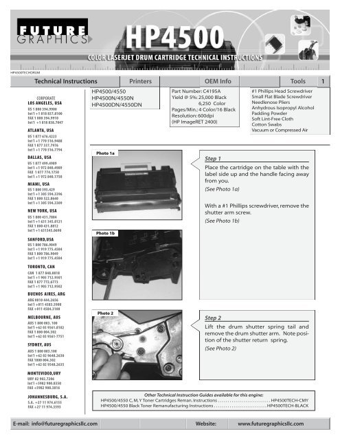
Part Number: C4195A<br />
Yield @ 5%: 25,000 Black<br />
6,250 Color<br />
Pages/Min.: 4 Color/16 Black<br />
Resolution: 600dpi<br />
(<strong>HP</strong> ImageRET 2400)<br />
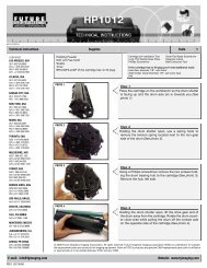
Step 1<br />
#1 Phillips Head Screwdriver<br />
Small Flat Blade Screwdriver<br />
Needlenose Pliers<br />
Anhydrous Isopropyl Alcohol<br />
Padding Powder<br />
Soft Lint-Free Cloth<br />
Cotton Swabs<br />
Vacuum or Compressed Air<br />
Place the cartridge on the table with the<br />
label side up and the handle facing away<br />
from you.<br />
(See Photo 1a)<br />
With a #1 Phillips screwdriver, remove the<br />
shutter arm screw.<br />
(See Photo 1b)<br />
Step 2<br />
Lift the drum shutter spring tail and<br />
remove the drum shutter arm. Note position<br />
of the shutter return spring.<br />
(See Photo 2)<br />
MONTEVIDEO,URY<br />
URY 02 902.7206<br />
Int’l +5982 900.8358<br />
FAX +5982 908.3816<br />
JOHANNESBURG, S.A.<br />
S.A. +27 11 974.6155<br />
FAX +27 11 974.3593<br />
Other <strong>Technical</strong> Instruction Guides available for this engine:<br />
<strong>HP</strong><strong>4500</strong>/4550 C, M, Y Toner Cartridges Reman. <strong>Instructions</strong> . . . . . . . . . . . . . . . . . . . . . . . . . . . <strong>HP</strong><strong>4500</strong>TECH-CMY<br />
<strong>HP</strong><strong>4500</strong>/4550 Black Toner Remanufacturing <strong>Instructions</strong> . . . . . . . . . . . . . . . . . . . . . . . . . . . <strong>HP</strong><strong>4500</strong>TECH-BLACK<br />
E-mail: info@futuregraphicsllc.com Website: www.futuregraphicsllc.com
2 <strong>HP</strong><strong>4500</strong> <strong>Technical</strong> <strong>Instructions</strong><br />
Notes<br />
Photo 3a<br />
Step 3<br />
Slide the shutter wire out on each side<br />
and set aside for now.<br />
(See Photo 3a and 3b)<br />
Photo 3b<br />
Photo 4<br />
Step 4<br />
Remove the seven (7) Phillips head<br />
screws from the left side plate.<br />
(See Photo 4)<br />
Photo 5<br />
Step 5<br />
Pull off the blue knob on the end of the<br />
drum shaft.<br />
(See Photo 5)<br />
Photo 6<br />
Step 6<br />
Turn the cartridge and remove the six (6)<br />
phillips head screws from the right side<br />
plate .<br />
(See Photo 6)<br />
Need trust-worthy, detailed <strong>Technical</strong><br />
<strong>Instructions</strong> for another engine?<br />
V isit: www.futuregraphicsllc.com
<strong>HP</strong><strong>4500</strong> <strong>Technical</strong> <strong>Instructions</strong> 3<br />
Photo 7<br />
Step 7<br />
Carefully remove the right-side plate.<br />
(See Photo 7)<br />
Notes<br />
Photo 8<br />
Step 8<br />
With the assembly inverted, remove the<br />
left side plate while balancing the drum<br />
in its normal position.<br />
(See Photo 8)<br />
Photo 9<br />
Step 9<br />
Remove the drum.<br />
(See Photo 9)<br />
Photo 10<br />
Step 10<br />
Remove the PCR cover by inserting a flat<br />
blade screwdriver in the center slot and<br />
release the latch.<br />
(See Photo 10)<br />
Need help with a particular remanufacturing<br />
problem?<br />
Call the <strong>Technical</strong> Resource Center from<br />
8am - 5pm PST: 800 394.9900
4 <strong>HP</strong><strong>4500</strong> <strong>Technical</strong> <strong>Instructions</strong><br />
Notes<br />
Photo 11<br />
Step11<br />
Remove the PCR, wipe clean with a soft,<br />
dry cloth and set aside.<br />
(See Photo 11)<br />
Photo 12<br />
Step12<br />
Remove the two Phillips head machine<br />
screws holding the wiper blade in position.<br />
(See Photo 12)<br />
Photo 13a<br />
Photo 13b<br />
Step 13<br />
Note the stabilizer bar attached to the<br />
wiper blade with two (2) long shouldered<br />
screws.<br />
(See Photo13a)<br />
The stabilizer bar must be moved to the<br />
new wiper blade. Note the correct position<br />
before removing it from the used<br />
part. Apply the adhesive strip to the stabilizer<br />
bar and carefully affix to the new<br />
blade. Anchor with two (2) screws.<br />
(See Photo13b)<br />
Photo 14<br />
Step 14<br />
Remove the chip housing located on the<br />
left side of the cartridge by removing the<br />
two Phillips head screws from the bracket.<br />
(See Photo 14)<br />
Need trust-worthy, detailed <strong>Technical</strong><br />
<strong>Instructions</strong> for another engine?<br />
V isit: www.futuregraphicsllc.com<br />
Photo 15<br />
Step 15<br />
Replace the chip with a new one by prying<br />
up on the old one to extract it. Press a<br />
new chip into position. Follow the<br />
detailed instruction printed on the<br />
replacement chip label.<br />
NOTE: Used chips can be sent into Future<br />
Graphics to be reset.<br />
(See Photo 15)
<strong>HP</strong><strong>4500</strong> <strong>Technical</strong> <strong>Instructions</strong> 5<br />
Photo 16<br />
Step 16<br />
Note the position of the auger gears.<br />
Remove the nine gears from the side of<br />
the cartridge.<br />
(See Photo 16)<br />
Notes<br />
Photo 17<br />
Step 17<br />
Using dry, compressed air, blow out the<br />
waste toner through the auger gear<br />
holes.<br />
(See Photo 17)<br />
NOTE: It is very important to get all the<br />
toner out of the waste unit. Failure to do<br />
so may result in a premature “<strong>Drum</strong> Life<br />
Low” or “<strong>Drum</strong> Life Out” error message.<br />
Step 18<br />
Reinstall the waste hopper gears.<br />
Step 19<br />
Reinstall the chip housing with the two (2) Phillips head screws.<br />
Photo 20<br />
Step 20<br />
Inspect the mylar recovery blade for damage,<br />
kinks, or waves. Replace if necessary.<br />
(See Photo 20)<br />
Photo 21<br />
Step 21<br />
Install wiper blade assembly and adjust<br />
the position with a blade spacing tool.<br />
(See Photo 21)<br />
Step 22<br />
Reinstall the cleaned replacement PCR.<br />
Need help with a particular remanufacturing<br />
problem?<br />
Call the <strong>Technical</strong> Resource Center from<br />
8am - 5pm PST: 800 394.9900
6 <strong>HP</strong><strong>4500</strong> <strong>Technical</strong> <strong>Instructions</strong><br />
Notes<br />
Photo 23a<br />
Photo 23b<br />
Step 23<br />
Put the padding powder on wiper blade<br />
and drum.<br />
(See Photo 23a)<br />
Install drum left and right side and rotate<br />
the drum toward the wiper blade while<br />
wiping off any powder from the PCR.<br />
Continue turning and wiping until the<br />
PCR is free of any powder.<br />
(See Photo 23b)<br />
Step 24<br />
Finish assembly in reverse order of disassembly.<br />
Future Graphics (FG) is a distributor of compatible replacement parts and products for imagining equipment.<br />
None of FG's products are genuine OEM replacement parts and no affiliation or sponsorship is to be implied between FG and any OEM.<br />
E-mail: info@futuregraphicsllc.com Website: www.futuregraphicsllc.com