Spatial confinement of ultrasonic force fields in microfluidic channels
Spatial confinement of ultrasonic force fields in microfluidic channels
Spatial confinement of ultrasonic force fields in microfluidic channels

Create successful ePaper yourself
Turn your PDF publications into a flip-book with our unique Google optimized e-Paper software.
Ultrasonics 49 (2009) 112–119<br />
Contents lists available at ScienceDirect<br />
Ultrasonics<br />
journal homepage: www.elsevier.com/locate/ultras<br />
<strong>Spatial</strong> <strong>conf<strong>in</strong>ement</strong> <strong>of</strong> <strong>ultrasonic</strong> <strong>force</strong> <strong>fields</strong> <strong>in</strong> micr<strong>of</strong>luidic <strong>channels</strong><br />
Otto Manneberg a , S. Melker Hagsäter b , Jessica Svennebr<strong>in</strong>g a , Hans M. Hertz a , Jörg P. Kutter b ,<br />
Henrik Bruus b , Mart<strong>in</strong> Wiklund a, *<br />
a Biomedical and X-ray Physics, Royal Institute <strong>of</strong> Technology, KTH-AlbaNova, SE-106 91 Stockholm, Sweden<br />
b Department <strong>of</strong> Micro- and Nanotechnology, Technical University <strong>of</strong> Denmark, DTU Nanotech, Build<strong>in</strong>g 345 East, DK-2800 Kongens Lyngby, Denmark<br />
article<br />
<strong>in</strong>fo<br />
abstract<br />
Article history:<br />
Received 21 January 2008<br />
Received <strong>in</strong> revised form 9 June 2008<br />
Accepted 19 June 2008<br />
Available onl<strong>in</strong>e 8 July 2008<br />
PACS:<br />
43.25.Gf<br />
Keywords:<br />
Ultrasonic manipulation<br />
Acoustic radiation <strong>force</strong><br />
Micr<strong>of</strong>luidic chip<br />
Particle image velocimetry<br />
<strong>Spatial</strong> <strong>conf<strong>in</strong>ement</strong><br />
Cell handl<strong>in</strong>g<br />
We demonstrate and <strong>in</strong>vestigate multiple localized <strong>ultrasonic</strong> manipulation functions <strong>in</strong> series <strong>in</strong> micr<strong>of</strong>luidic<br />
chips. The manipulation functions are based on spatially separated and conf<strong>in</strong>ed <strong>ultrasonic</strong> primary<br />
radiation <strong>force</strong> <strong>fields</strong>, obta<strong>in</strong>ed by local match<strong>in</strong>g <strong>of</strong> the resonance condition <strong>of</strong> the micr<strong>of</strong>luidic<br />
channel. The channel segments are remotely actuated by the use <strong>of</strong> frequency-specific external transducers<br />
with refract<strong>in</strong>g wedges placed on top <strong>of</strong> the chips. The <strong>force</strong> field <strong>in</strong> each channel segment is characterized<br />
by the use <strong>of</strong> micrometer-resolution particle image velocimetry (micro-PIV). The <strong>conf<strong>in</strong>ement</strong> <strong>of</strong><br />
the <strong>ultrasonic</strong> <strong>fields</strong> dur<strong>in</strong>g s<strong>in</strong>gle- or dual-segment actuation, as well as the cross-talk between two adjacent<br />
<strong>fields</strong>, is characterized and quantified. Our results show that the field <strong>conf<strong>in</strong>ement</strong> typically scales<br />
with the acoustic wavelength, and that the cross-talk is <strong>in</strong>significant between adjacent <strong>fields</strong>. The goal<br />
is to def<strong>in</strong>e design strategies for implement<strong>in</strong>g several spatially separated <strong>ultrasonic</strong> manipulation functions<br />
<strong>in</strong> series for use <strong>in</strong> advanced particle or cell handl<strong>in</strong>g and process<strong>in</strong>g applications. One such pro<strong>of</strong><strong>of</strong>-concept<br />
application is demonstrated, where flow-through-mode operation <strong>of</strong> a chip with flow splitt<strong>in</strong>g<br />
elements is used for two-dimensional pre-alignment and addressable merg<strong>in</strong>g <strong>of</strong> particle tracks.<br />
Ó 2008 Elsevier B.V. All rights reserved.<br />
1. Introduction<br />
Ultrasonic stand<strong>in</strong>g wave (USW) manipulation technology <strong>in</strong><br />
micr<strong>of</strong>luidic chips has recently emerged as a powerful tool for,<br />
e.g., cont<strong>in</strong>uous alignment, separation, trapp<strong>in</strong>g and aggregation<br />
<strong>of</strong> micrometer-sized particles or cells [1,2]. We have previously<br />
shown that it is possible to generate <strong>in</strong>dependent stand<strong>in</strong>g wave<br />
<strong>fields</strong> <strong>in</strong> different directions <strong>in</strong>side a micr<strong>of</strong>luidic channel, where<br />
each field is addressed by a specific external transducer [3]. However,<br />
a rema<strong>in</strong><strong>in</strong>g problem is that USW manipulation technology<br />
has poor spatial localization <strong>in</strong> comparison to alternative contactless<br />
manipulation methods such as dielectrophoresis [4] and optical<br />
tweezers [5]. In the present paper, we demonstrate for the first<br />
time multiple spatially separated and conf<strong>in</strong>ed <strong>ultrasonic</strong> <strong>force</strong><br />
<strong>fields</strong> by microchannel design, with the aim <strong>of</strong> develop<strong>in</strong>g more<br />
advanced and complex lab-on-a-chip systems based on USW<br />
technology.<br />
One characteristic <strong>of</strong> the present USW manipulation technology<br />
(that differs from the characteristics <strong>of</strong> dielectrophoresis and optical<br />
tweezers), is the possibility to generate a uniform <strong>force</strong> field <strong>in</strong><br />
the entire fluid channel <strong>in</strong> a chip. For example, with USW technology<br />
it is possible to guide a particle or a cell through a micr<strong>of</strong>luidic<br />
* Correspond<strong>in</strong>g author. Tel.: +46 8 5537 8134; fax: + 46 8 5537 8466.<br />
E-mail address: mart<strong>in</strong>@biox.kth.se (M. Wiklund).<br />
chip at constant velocity and without any contact with the channel<br />
walls [3], or to separate particles from a suspension at high flow<br />
rates [2]. On the other hand, dielectrophoresis has been used <strong>in</strong><br />
more complex particle or cell process<strong>in</strong>g systems where several<br />
manipulation functions are located at different sites along the fluid<br />
channel [4]. Here, different micro-electrode geometries def<strong>in</strong>e different<br />
addressable manipulation functions, each with high spatial<br />
accuracy <strong>in</strong> terms <strong>of</strong> both localization and <strong>conf<strong>in</strong>ement</strong> <strong>of</strong> the correspond<strong>in</strong>g<br />
dielectrophoretic <strong>force</strong> field. Thus, advanced s<strong>in</strong>gleparticle<br />
handl<strong>in</strong>g and process<strong>in</strong>g systems are realized by comb<strong>in</strong><strong>in</strong>g<br />
several consecutive manipulation functions (such as alignment,<br />
park<strong>in</strong>g, sort<strong>in</strong>g, separation, etc.) and a cont<strong>in</strong>uous driv<strong>in</strong>g fluid<br />
flow. In comparison to dielectrophoresis, USW technology has a<br />
much lower degree <strong>of</strong> <strong>in</strong>strumentation complexity [6], and also<br />
better prospects for gentle and long-term handl<strong>in</strong>g <strong>of</strong> sensitive<br />
cells [7,8]. Therefore, it is <strong>of</strong> <strong>in</strong>terest to <strong>in</strong>vestigate if USW technology<br />
can be used <strong>in</strong> advanced particle process<strong>in</strong>g systems based on<br />
comb<strong>in</strong>ations <strong>of</strong> several spatially separated and localized manipulation<br />
functions.<br />
To date, several different methods have been suggested for coupl<strong>in</strong>g<br />
<strong>of</strong> ultrasound from a transducer <strong>in</strong>to a well-def<strong>in</strong>ed stand<strong>in</strong>g<br />
wave <strong>in</strong> a micr<strong>of</strong>luidic chip. The standard approach is based on the<br />
one-dimensional resonator that consists <strong>of</strong> a stack <strong>of</strong> plane-parallel<br />
layers: a PZT layer, a coupl<strong>in</strong>g layer, a fluid layer and a reflect<strong>in</strong>g<br />
layer [7,9,10], or with the reflect<strong>in</strong>g layer exchanged for another<br />
0041-624X/$ - see front matter Ó 2008 Elsevier B.V. All rights reserved.<br />
doi:10.1016/j.ultras.2008.06.012
O. Manneberg et al. / Ultrasonics 49 (2009) 112–119 113<br />
coupl<strong>in</strong>g layer and PZT layer [11,12]. However, it has been shown<br />
that <strong>in</strong> silicon/glass-based micr<strong>of</strong>luidic chips, it is not <strong>of</strong> critical<br />
importance how the system is excited. For example, one reported<br />
method is based on excit<strong>in</strong>g the channel perpendicularly to the<br />
outgo<strong>in</strong>g wave from an external transducer [2]. An alternative approach,<br />
developed <strong>in</strong> our lab, is based on oblique coupl<strong>in</strong>g via a<br />
refract<strong>in</strong>g wedge on an external transducer for controlled direct<strong>in</strong>g<br />
<strong>of</strong> the <strong>in</strong>cident wave <strong>in</strong>to the fluid channel [6]. Another reported<br />
method is based on bend<strong>in</strong>g vibrations <strong>of</strong> a glass plate <strong>in</strong> contact<br />
with the fluid channel [13]. However, all these methods typically<br />
result <strong>in</strong> a stand<strong>in</strong>g wave field that extends along the whole fluid<br />
channel. Thus, it is difficult to conf<strong>in</strong>e an <strong>ultrasonic</strong> field <strong>in</strong> a chip<br />
by wave propagation from an external transducer only.<br />
We note that by <strong>in</strong>tegrat<strong>in</strong>g the PZT elements <strong>in</strong> the fluid channel,<br />
localization and <strong>conf<strong>in</strong>ement</strong> <strong>of</strong> an <strong>ultrasonic</strong> stand<strong>in</strong>g wave<br />
field can be obta<strong>in</strong>ed [14–16]. In such devices, the extent <strong>of</strong> the<br />
<strong>ultrasonic</strong> field is similar to the size <strong>of</strong> the PZT element (typically,<br />
0.5–0.8 mm wide square elements designed for operation around<br />
10 MHz). However, the generated stand<strong>in</strong>g wave field has a complicated<br />
lateral distribution due to strong near-field effects. Furthermore,<br />
the experimental arrangement is more complicated<br />
and less flexible than <strong>in</strong> similar devices us<strong>in</strong>g external transducers<br />
(e.g., <strong>in</strong> Refs. 2,6). Another restriction with channel-<strong>in</strong>tegrated PZT<br />
elements is the limited optical access, which excludes trans-illum<strong>in</strong>ation<br />
microscopy techniques. F<strong>in</strong>ally, s<strong>in</strong>ce the PZT element is <strong>in</strong><br />
direct contact with the fluid <strong>in</strong>side the microchannel, the biocompatibility<br />
may be reduced due to, e.g., heat<strong>in</strong>g (cf. Ref. 8).<br />
In the present paper, we demonstrate for the first time spatial<br />
localization, separation and <strong>conf<strong>in</strong>ement</strong> <strong>of</strong> multiple <strong>ultrasonic</strong><br />
stand<strong>in</strong>g wave <strong>fields</strong> <strong>in</strong> optically transparent micr<strong>of</strong>luidic chips utiliz<strong>in</strong>g<br />
remote actuation from external transducers. The method is<br />
based on local match<strong>in</strong>g <strong>of</strong> the channel width to the transducer frequency<br />
<strong>in</strong> chips with non-uniform channel cross-sections. We<br />
present results from two different chip designs; one for <strong>in</strong>vestigat<strong>in</strong>g<br />
the dependence <strong>of</strong> the <strong>conf<strong>in</strong>ement</strong> on small differences <strong>in</strong><br />
channel width, and one with flow splitt<strong>in</strong>g elements designed for<br />
two-dimensional alignment and addressable merg<strong>in</strong>g <strong>of</strong> particle<br />
tracks. The <strong>ultrasonic</strong> <strong>fields</strong> are quantified by the use <strong>of</strong> micrometer-resolution<br />
particle image velocimetry (micro-PIV) [17] dur<strong>in</strong>g<br />
actuation <strong>of</strong> a s<strong>in</strong>gle channel segment, or <strong>of</strong> two adjacent channel<br />
segments simultaneously. The results are important for the understand<strong>in</strong>g<br />
<strong>of</strong> how <strong>ultrasonic</strong> resonances are formed <strong>in</strong> micr<strong>of</strong>luidic<br />
chips, as well as for develop<strong>in</strong>g future particle handl<strong>in</strong>g systems<br />
with tailor-made, localized and conf<strong>in</strong>ed <strong>ultrasonic</strong> resonances by<br />
microchannel design.<br />
2. Theoretical background<br />
As a basic condition for the design process, we assume that an<br />
<strong>ultrasonic</strong> resonance can be localized and conf<strong>in</strong>ed through proper<br />
match<strong>in</strong>g <strong>of</strong> the width and height (relative to the acoustic wavelength)<br />
<strong>of</strong> a particular channel segment. Furthermore, we assume<br />
that the total three-dimensional resonant field <strong>in</strong> a chip is a superposition<br />
<strong>of</strong> one-dimensional and spatially harmonic resonances <strong>in</strong><br />
orthogonal directions, and that each such one-dimensional resonance<br />
can be remotely excited by an external frequency-specific<br />
transducer. These conditions are the start<strong>in</strong>g po<strong>in</strong>t for the theoretical<br />
background presented below. However, we are aware that the<br />
conditions are simplifications. In reality, the resonances <strong>in</strong> a micr<strong>of</strong>luidic<br />
chip should be regarded as full three-dimensional <strong>fields</strong> that<br />
extend not only <strong>in</strong> the fluid channel but rather <strong>in</strong> the whole chip<br />
structure. Therefore, the degree <strong>of</strong> localization and <strong>conf<strong>in</strong>ement</strong><br />
<strong>of</strong> the field <strong>in</strong>to a particular part <strong>of</strong> the fluid channel is a function<br />
<strong>of</strong> not only the channel geometry, but also the acoustic impedances<br />
and geometries <strong>of</strong> all support<strong>in</strong>g layers to the channel structure,<br />
<strong>in</strong>clud<strong>in</strong>g the whole fluid channel itself [18]. The validity <strong>of</strong> our<br />
simplified conditions below is further discussed <strong>in</strong> Section 5.<br />
2.1. Ultrasonic stand<strong>in</strong>g wave manipulation<br />
It has long been known that particles <strong>in</strong> an <strong>ultrasonic</strong> stand<strong>in</strong>g<br />
wave will be subjected to a primary radiation <strong>force</strong> F PR , which attracts<br />
suspended particles to the nodes or ant<strong>in</strong>odes <strong>of</strong> the stand<strong>in</strong>g<br />
wave depend<strong>in</strong>g on the acoustic properties <strong>of</strong> the particles<br />
relative to the surround<strong>in</strong>g medium [19]. Gor’kov has shown that<br />
the <strong>force</strong> on a particle <strong>of</strong> volume V <strong>in</strong> an arbitrary acoustic field<br />
is given by [20]<br />
F PR ¼<br />
<br />
hp<br />
Vr 2 i<br />
f 1<br />
2qc<br />
3<br />
2 qf hv 2 i<br />
2<br />
2<br />
<br />
where the brackets denote time-averag<strong>in</strong>g and q and c are the density<br />
and speed <strong>of</strong> sound <strong>in</strong> the medium. f 1 and f 2 are contrast factors<br />
which depend on the speed <strong>of</strong> sound and the density <strong>of</strong> the medium<br />
and particle accord<strong>in</strong>g to<br />
<br />
qc 2<br />
q p<br />
q<br />
f 1 ¼ 1 and f<br />
q p<br />
c 2 2 ¼ 2<br />
ð2Þ<br />
p<br />
2q p<br />
þ q<br />
where the <strong>in</strong>dex p <strong>in</strong>dicates ‘‘particle”. In the simple case <strong>of</strong> a onedimensional<br />
spatially s<strong>in</strong>usoidal stand<strong>in</strong>g wave <strong>in</strong> the x direction,<br />
Eq. (1) reduces to [20]<br />
F PR ðxÞ ¼ Vp2 0 k <br />
f<br />
4qc 2 1 þ 3 <br />
2 f 2 s<strong>in</strong>ð2kxÞ<br />
ð3Þ<br />
where k is the wavenumber, def<strong>in</strong>ed as k =2p/k where k is the<br />
acoustic wavelength. As mentioned above, a microchip conta<strong>in</strong><strong>in</strong>g<br />
a microchannel is a complex resonator. However, to a first approximation,<br />
the <strong>force</strong>s <strong>in</strong> such a channel can be obta<strong>in</strong>ed by simple<br />
superposition <strong>of</strong> plane-parallel resonators <strong>in</strong> perpendicular directions,<br />
each with a <strong>force</strong> field given by Eq. (3) [21]. This approximation<br />
(i.e., assum<strong>in</strong>g no coupl<strong>in</strong>g between the orthogonal <strong>fields</strong>) is<br />
sufficiently accurate if the superposed <strong>fields</strong> do not operate at frequencies<br />
that are multiples <strong>of</strong> each other [22].<br />
2.2. Force field quantification by micro-PIV<br />
In the present work, the primary radiation <strong>force</strong> field F PR is<br />
quantified <strong>in</strong> two dimensions (x and z, cf. Fig. 1) us<strong>in</strong>g the micro-<br />
PIV technique, <strong>in</strong> which the motion <strong>of</strong> tracer particles <strong>in</strong> the form<br />
<strong>of</strong> velocity vector <strong>fields</strong> is acquired from consecutive image frames<br />
[17]. F PR is proportional to the bead velocity given that no other<br />
<strong>force</strong>s or flows are present, and that the time after activat<strong>in</strong>g a<br />
transducer is well above the time constant s p for reach<strong>in</strong>g <strong>force</strong><br />
equilibrium between F PR and the viscous Stokes drag. The time<br />
constant s p is given by [23]<br />
s p ¼ 2q p<br />
r 2 =9g p ð4Þ<br />
where r p is the radius <strong>of</strong> the particle and g is the viscosity <strong>of</strong> the liquid<br />
medium. When represent<strong>in</strong>g the relative <strong>force</strong> <strong>fields</strong> with<br />
velocity <strong>fields</strong>, possible sources <strong>of</strong> error are, e.g., acoustic stream<strong>in</strong>g<br />
[24] and sedimentation by gravity. Acoustic stream<strong>in</strong>g will, through<br />
viscous drag, <strong>in</strong>fluence the particles with a <strong>force</strong> proportional to the<br />
particle radius r. AsF PR is proportional to r 3 , the stream<strong>in</strong>g will typically<br />
dom<strong>in</strong>ate when the particles are small (r 0.5 lm) whereas<br />
F PR will typically dom<strong>in</strong>ate when the particles are larger (r 5 lm),<br />
as <strong>in</strong> our experiments. The time constant s sed for sedimentation a<br />
(vertical) distance h <strong>in</strong> a fluid channel is given by<br />
s sed ¼<br />
h 9gh<br />
¼<br />
v sed 2ðq p<br />
qÞr 2 p g ð5Þ<br />
ð1Þ
114 O. Manneberg et al. / Ultrasonics 49 (2009) 112–119<br />
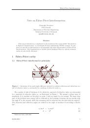
In our experiments, we used two different chip designs (described<br />
<strong>in</strong> detail <strong>in</strong> the next paragraph). Fig. 1a is a photograph<br />
<strong>of</strong> one <strong>of</strong> the chips used with mounted transducers and Fig. 1b<br />
illustrates the pr<strong>in</strong>ciples <strong>of</strong> the oblique coupl<strong>in</strong>g method (described<br />
<strong>in</strong> Refs. [3,6]). Both chips are fabricated from 51.4 22 mm 2 glasssilicon-glass<br />
stacks with the microchannel plasma etched <strong>in</strong>to the<br />
silicon layer (GeSim, Germany). The bottom glass plate <strong>of</strong> both<br />
chips is 200 lm thick, i.e., close to standard microscope coverslip<br />
thickness. This allows <strong>in</strong>vestigation <strong>of</strong> the channel us<strong>in</strong>g any k<strong>in</strong>d<br />
<strong>of</strong> high-resolution optical microscopy, <strong>in</strong>clud<strong>in</strong>g both trans- and<br />
epi-illum<strong>in</strong>ation techniques. The transducers were fabricated by<br />
glu<strong>in</strong>g planar PZT elements (Pz26, Ferroperm, Denmark) to alum<strong>in</strong>um<br />
wedges (cf. Fig. 1a) with a cross-section <strong>of</strong> 5 5mm 2 , and<br />
driven at peak-to-peak voltages up to 13 V by separate function<br />
generators operat<strong>in</strong>g at different frequencies with<strong>in</strong> the range<br />
1.5–7 MHz. The alum<strong>in</strong>um wedges were attached to the chip (cf.<br />
Fig. 1a) us<strong>in</strong>g a quick-dry<strong>in</strong>g and water-soluble adhesive gel (Tensive,<br />
Parker Laboratories, USA).<br />
The channel designs <strong>in</strong> the two <strong>in</strong>vestigated chips are schematically<br />
illustrated <strong>in</strong> Fig. 2. In both designs, the channel height is<br />
110 lm and the widths are specifically designed to spatially conf<strong>in</strong>e<br />
resonances to a certa<strong>in</strong> part <strong>of</strong> the channel by match<strong>in</strong>g <strong>of</strong><br />
width and frequency as to fulfill the simplified resonance condition<br />
L ¼ m 2 k ¼ m 2 c f<br />
ð6Þ<br />
Fig. 1. Photograph (a) and schematic (not to scale) <strong>of</strong> cross-section (b) <strong>of</strong> the ‘‘Split<br />
Chip” with mounted transducers. The ruler scale is <strong>in</strong> millimeter. In (b), the dashed<br />
l<strong>in</strong>es represent wavefronts <strong>in</strong>cident at an angle typical for manipulation <strong>in</strong> the x<br />
direction.<br />
where L is the channel width <strong>in</strong> the relevant direction, m is a positive<br />
<strong>in</strong>teger, k is the acoustic wavelength <strong>in</strong> the fluid, c is the speed<br />
<strong>of</strong> sound <strong>in</strong> the fluid and f is the acoustic frequency. The first chip<br />
(the ‘‘Step Chip”, cf. Fig. 2a) has a straight channel with three 15-<br />
mm long sections <strong>of</strong> different width (643 lm, 600 lm and<br />
500 lm). This chip is designed to utilize the <strong>fields</strong> from four different<br />
transducers, three <strong>of</strong> which act to focus particles <strong>in</strong> the x direction<br />
<strong>in</strong> each <strong>of</strong> the segments and one to levitate them <strong>in</strong> the y<br />
direction aga<strong>in</strong>st the <strong>force</strong> <strong>of</strong> gravity. The second chip (the ‘‘Split<br />
Chip”) has a more complex channel structure <strong>in</strong>clud<strong>in</strong>g two flow<br />
splitt<strong>in</strong>g elements, as illustrated <strong>in</strong> Fig. 2b. This chip is designed<br />
to use the <strong>fields</strong> from five different transducers operat<strong>in</strong>g at different<br />
frequencies to excite resonances <strong>in</strong> different parts <strong>of</strong> the chip, as<br />
<strong>in</strong>dicated <strong>in</strong> Fig. 2b. Four <strong>of</strong> these can perform focus<strong>in</strong>g <strong>of</strong> the particles<br />
<strong>in</strong> the x direction, and one is used to levitate the beads <strong>in</strong><br />
the y direction. Thus, the operator can choose between merg<strong>in</strong>g particle<br />
tracks 1 + 2, tracks 2 + 3 or all tracks (cf. Fig. 2b). This pr<strong>in</strong>ciple<br />
where v sed is the sedimentation speed and g is the acceleration <strong>of</strong><br />
gravity. A typical value <strong>of</strong> s sed <strong>in</strong> our micro<strong>channels</strong> is 1 m<strong>in</strong>ute<br />
(for 5-lm-diam. polyamide beads <strong>in</strong> water, and choos<strong>in</strong>g h as half<br />
the channel height), and is therefore <strong>of</strong> little importance.<br />
2.3. Comb<strong>in</strong>ed <strong>ultrasonic</strong> stand<strong>in</strong>g wave manipulation and flow<br />
At the employed flow level (0.1 lL/s) <strong>in</strong> our flow-through<br />
experiments (cf. Section 4.2), the flow is lam<strong>in</strong>ar <strong>in</strong> the whole<br />
channel structure (e.g., the Reynolds number is 1). This means<br />
that once the <strong>force</strong> from the <strong>ultrasonic</strong> field has positioned a particle<br />
<strong>in</strong> a streaml<strong>in</strong>e, it will stay <strong>in</strong> that streaml<strong>in</strong>e until subjected<br />
to an external <strong>force</strong>. In our experiments, we dist<strong>in</strong>guish between a<br />
streaml<strong>in</strong>e (path <strong>of</strong> a fluid element) and a particle track (path <strong>of</strong> a<br />
suspended particle).<br />
3. Experimental arrangement<br />
Fig. 2. Schematics (not to scale) top-view <strong>of</strong> the two employed chips; the ‘‘Step<br />
Chip” (a) and the ‘‘Split Chip” (b). The horizontal l<strong>in</strong>es <strong>in</strong> the <strong>channels</strong> <strong>in</strong>dicate the<br />
pressure node pattern, i.e., the l<strong>in</strong>es to which particles are focused. The th<strong>in</strong> dashed<br />
l<strong>in</strong>es <strong>in</strong> (b) mark the boundaries <strong>of</strong> the spatially conf<strong>in</strong>ed resonances <strong>in</strong> each<br />
channel segment. The levitator transducers operat<strong>in</strong>g at 7.1 MHz is not shown, but<br />
is placed to the far right <strong>in</strong> experiments.
O. Manneberg et al. / Ultrasonics 49 (2009) 112–119 115<br />
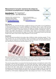
Fig. 3. Characterization <strong>of</strong> the primary radiation <strong>force</strong> field F PR <strong>in</strong> the ‘‘Step Chip”<br />
(cf. Fig. 2a), measured by micrometer-resolution particle image velocimetry (micro-<br />
PIV). Actuation at 2.62 MHz <strong>of</strong> the left channel segment (a), at 3.51 MHz <strong>of</strong> the right<br />
channel segment (b), and at 2.62 and 3.51 MHz <strong>of</strong> both channel segments<br />
simultaneously (c). White arrows <strong>in</strong>dicate the relative sizes and directions <strong>of</strong> the<br />
<strong>force</strong>s immediately after actuation is <strong>in</strong>itialized. Dark regions <strong>in</strong>dicate the bead<br />
pattern after 10 s <strong>of</strong> actuation. The length <strong>of</strong> the coord<strong>in</strong>ate arrows <strong>in</strong> (a)<br />
corresponds to a velocity <strong>of</strong> 10 lm/s.<br />
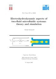
Fig. 4. Characterization <strong>of</strong> the primary radiation <strong>force</strong> field F PR <strong>in</strong> the ‘‘Split Chip”<br />
(cf. Fig. 2b), measured by micrometer-resolution particle image velocimetry (micro-<br />
PIV). Actuation at 2.94 MHz <strong>of</strong> the lower right channel segment (a), at 2.10 MHz <strong>of</strong><br />
the left channel segment (b), and at 2.94 and 2.10 MHz <strong>of</strong> both channel segments<br />
simultaneously (c). White arrows <strong>in</strong>dicate the relative sizes and directions <strong>of</strong> the<br />
<strong>force</strong>s immediately after actuation is <strong>in</strong>itialized. Dark regions <strong>in</strong>dicate the bead<br />
pattern after 10 s <strong>of</strong> actuation. The length <strong>of</strong> the coord<strong>in</strong>ate arrows <strong>in</strong> (a)<br />
corresponds to a velocity <strong>of</strong> 10 lm/s.<br />
could easily be expanded, and more <strong>in</strong>- or outlets added, to accommodate<br />
to the needs <strong>of</strong> a specific application (cf. Section 5).<br />
Each resonance frequency was identified by tun<strong>in</strong>g the applied<br />
transducer frequency <strong>in</strong> small steps around the expected frequency<br />
(accord<strong>in</strong>g to Eq. 6) and observ<strong>in</strong>g the particle manipulation response<br />
<strong>in</strong> the correspond<strong>in</strong>g channel segment. The operat<strong>in</strong>g frequency<br />
was then manually selected via the optimal ability to<br />
position particles quickly and uniformly <strong>in</strong>to the nodes. Micro-<br />
PIV measurements were performed at all sites where the <strong>channels</strong><br />
change width. To <strong>in</strong>vestigate the degree <strong>of</strong> spatial <strong>conf<strong>in</strong>ement</strong>,<br />
measurements were made with operation <strong>of</strong> either <strong>of</strong> the two or<br />
both transducers correspond<strong>in</strong>g to actuation <strong>of</strong> the channel segments<br />
on each sides <strong>of</strong> the change <strong>in</strong> channel width (cf. Section
116 O. Manneberg et al. / Ultrasonics 49 (2009) 112–119<br />
Fig. 6. Demonstration <strong>of</strong> addressable merg<strong>in</strong>g <strong>of</strong> particle tracks <strong>in</strong> the ‘‘Split Chip”.<br />
Panels (a) and (b) show the particle tracks without and with actuation <strong>of</strong> the upper<br />
left channel segment, respectively. Panel (c) shows merg<strong>in</strong>g <strong>of</strong> the two lower<br />
particle tracks by actuation <strong>of</strong> the lower left channel segment. The chip site <strong>in</strong> (a)<br />
and (b) is located at the 2.5-MHz transducer, and the chip site <strong>in</strong> (c) is located at the<br />
3.0-MHz transducer (cf. Fig. 2b).<br />
were recorded <strong>in</strong> pairs with a CCD camera (HiSense MkII, Dantec<br />
Dynamics, Denmark) mounted on an <strong>in</strong>verted microscope (Axio-<br />
Vert 100, Zeiss, Germany) with a 10 /0.25 NA objective. The sample<br />
was illum<strong>in</strong>ated <strong>in</strong> back-lit mode by a light emitt<strong>in</strong>g diode (K2,<br />
Lumileds, USA) [25]. The velocity vector <strong>fields</strong> were generated<br />
us<strong>in</strong>g essentially the same protocol as described by Hagsäter<br />
et al. [18]. Before each new micro-PIV measurement, the channel<br />
was flushed and re-seeded to give a homogenous start<strong>in</strong>g distribution<br />
<strong>of</strong> beads.<br />
4. Results<br />
Fig. 5. Quantification <strong>of</strong> the field <strong>conf<strong>in</strong>ement</strong> and cross-talk <strong>in</strong> the ‘‘Split Chip” (cf.<br />
Fig. 4). The diagrams present the x components (cf. coord<strong>in</strong>ate system <strong>in</strong> Fig. 4) <strong>of</strong><br />
the velocity vectors along 31 z-axes equally spaced <strong>in</strong> the x direction. (a) Shows the<br />
x component <strong>of</strong> the sum <strong>of</strong> the velocity <strong>fields</strong> acquired when actuat<strong>in</strong>g the two<br />
channel segments separately (cf. Fig. 4a and b). (b) Shows the x component <strong>of</strong> the<br />
velocity field acquired when actuat<strong>in</strong>g both channel segments simultaneously (cf.<br />
Fig. 4c).<br />
4). We also demonstrate flow-through-mode operation with the<br />
Split Chip operated with up to four <strong>in</strong>dependent transducers<br />
simultaneously.<br />
Two different k<strong>in</strong>ds <strong>of</strong> particles were employed <strong>in</strong> the experiments;10.4<br />
lm green-fluorescent polystyrene beads (Bangs Labs,<br />
USA) for the flow-through experiments and 5 lm polyamide beads<br />
(Danish Phantom Design, Denmark) for the micro-PIV <strong>in</strong>vestigations.<br />
The beads were chosen for their resemblance to cells <strong>in</strong> both<br />
volume and acoustic properties. The beads were diluted <strong>in</strong> phosphate-buffered<br />
sal<strong>in</strong>e (PBS), pH 7.4, with 0.05% Tween-20 and<br />
<strong>in</strong>troduced <strong>in</strong>to the system by use <strong>of</strong> a syr<strong>in</strong>ge pump and Teflon<br />
(FEP) tub<strong>in</strong>g.<br />
In the flow-through-mode experiments (cf. Fig. 6), imag<strong>in</strong>g was<br />
performed us<strong>in</strong>g an <strong>in</strong>verted microscope (AxioVert 135 M, Zeiss,<br />
Germany) with a 2.5 /0.075 NA objective and a CCD camera (AxioCam<br />
HSc, Zeiss, Germany). In order to visualize both the beads<br />
and the microchannel, epi-flourescence and low-level trans-illum<strong>in</strong>ation<br />
were used simultaneously. For the micro-PIV measurements<br />
performed without flow (cf. Figs. 3 and 4), image frames<br />
In this section, we report on micro-PIV results when the two<br />
chips (the ‘‘Step Chip” and the ‘‘Split Chip”) are operated without<br />
flow dur<strong>in</strong>g <strong>ultrasonic</strong> actuation <strong>of</strong> one or several channel segments.<br />
The micro-PIV results are analyzed <strong>in</strong> order to quantify<br />
the spatial separation and <strong>conf<strong>in</strong>ement</strong> <strong>of</strong> the <strong>force</strong> <strong>fields</strong>, and possible<br />
cross-talk between two adjacent channel segments. Furthermore,<br />
we demonstrate flow-through operation <strong>of</strong> the Split Chip,<br />
which is designed for two-dimensional alignment and addressable<br />
merg<strong>in</strong>g <strong>of</strong> particle tracks.<br />
4.1. Micro-PIV measurements<br />
Micro-PIV measurements were made at all sites where the<br />
<strong>channels</strong> change width, both <strong>in</strong> the Step Chip and <strong>in</strong> the Split Chip<br />
(cf. Fig. 2). However, <strong>in</strong> order to m<strong>in</strong>imize the number <strong>of</strong> figures we<br />
have chosen to present results from one representative site <strong>in</strong> each<br />
chip, which is sufficient for the important conclusions. The results<br />
are presented as plots <strong>of</strong> the velocity vector <strong>fields</strong> (white arrows)<br />
superimposed with images <strong>of</strong> beads (dark regions) <strong>in</strong> the micro<strong>channels</strong><br />
(bright regions) (cf. Figs. 3 and 4). Typically, the vector<br />
field plots are averages <strong>of</strong> 10–15 data sets. The micro-PIV image<br />
frames were recorded immediately 1 after turn<strong>in</strong>g on the trans-<br />
1 ‘‘Immediately” means approximately a few tenths <strong>of</strong> a second after turn<strong>in</strong>g on the<br />
transducer(s). This is well above the time constant, s, for reach<strong>in</strong>g equilibrium<br />
between the radiation <strong>force</strong> and the viscous drag (s 1 ms, cf. Section 2.2), and well<br />
below the time to reach a static bead distribution <strong>in</strong> the channel (10 s).
O. Manneberg et al. / Ultrasonics 49 (2009) 112–119 117<br />
ducer(s), thus represent<strong>in</strong>g the <strong>in</strong>itial and transient motion <strong>of</strong> beads.<br />
In contrast, the bead images were acquired after a few seconds, thus<br />
represent<strong>in</strong>g the (near-)steady-state distribution <strong>of</strong> manipulated<br />
beads. F<strong>in</strong>ally, <strong>in</strong> order to <strong>in</strong>vestigate and compare the radiation<br />
<strong>force</strong> <strong>fields</strong> produced by <strong>in</strong>dividual transducers, no levitation (<strong>in</strong><br />
the y direction) was performed dur<strong>in</strong>g the micro-PIV measurements.<br />
4.1.1. Micro-PIV measurements <strong>in</strong> the Step Chip<br />
In Fig. 3, the results are presented from measurements at the<br />
transition region from a 600 lm wide channel (left side) to a<br />
643 lm wide channel (right side) <strong>in</strong> the Step Chip. In Fig. 3a the<br />
600-lm-wide segment is actuated at 2.62 MHz, <strong>in</strong> Fig. 3b the<br />
643-lm-wide segment is actuated at 3.51 MHz and <strong>in</strong> Fig. 3c both<br />
segments are actuated simultaneously at 2.62 and 3.51 MHz,<br />
respectively. Ideally, each <strong>force</strong> field should be conf<strong>in</strong>ed to its correspond<strong>in</strong>g<br />
channel segment (cf. Eq. 6). However, <strong>in</strong> Fig. 3a we see<br />
that the resonance ‘‘leaks” over to the adjacent channel segment.<br />
Although the <strong>force</strong>s are larger <strong>in</strong> the left segment, they are still significant<br />
<strong>in</strong> the right segment (i.e., on average a few times smaller to<br />
the right than to the left). Thus, a 7%-change <strong>in</strong> channel width is<br />
here not enough for fully conf<strong>in</strong><strong>in</strong>g the resonance to the proposed<br />
channel segment. On the other hand, the performance <strong>in</strong> Fig. 3b is<br />
much better <strong>in</strong> terms <strong>of</strong> <strong>conf<strong>in</strong>ement</strong>. Here, the <strong>force</strong>s <strong>in</strong> the left<br />
channel segment are <strong>in</strong>significant <strong>in</strong> comparison to the right segment,<br />
and the transition region (def<strong>in</strong>ed as the approximately distance<br />
from maximum to <strong>in</strong>significant <strong>force</strong>s <strong>in</strong> the z direction) is <strong>of</strong><br />
the order <strong>of</strong> k/4. F<strong>in</strong>ally, Fig. 3c shows the results when both channel<br />
segments are actuated simultaneously. Interest<strong>in</strong>gly, we see<br />
here that the ‘‘resonance-leakage” <strong>in</strong>to the right segment orig<strong>in</strong>at<strong>in</strong>g<br />
from actuation <strong>of</strong> the left segment (cf. Fig. 3a) is quenched by<br />
the actuation <strong>of</strong> the right segment. We also note that the vector<br />
field <strong>in</strong> Fig. 3c is not equal to the sum <strong>of</strong> the vector <strong>fields</strong> <strong>in</strong><br />
Fig. 3a and b. For example, the periodic variation <strong>of</strong> the <strong>force</strong> along<br />
the z direction <strong>in</strong> the right channel segment <strong>in</strong> Fig. 3c can not be<br />
derived from the vector <strong>fields</strong> <strong>in</strong> Fig. 3a and b.<br />
4.1.2. Micro-PIV measurements <strong>in</strong> the Split Chip<br />
In Fig. 4, the results from measurements at one site <strong>in</strong> the Split<br />
Chip are presented. The sub-figures show actuation at 2.94 MHz <strong>of</strong><br />
the lower right channel segment (Fig. 4a), actuation at 2.10 MHz <strong>of</strong><br />
the left channel segment (Fig. 4b), and actuation at 2.94 MHz and<br />
2.10 MHz <strong>of</strong> both segments simultaneously (Fig. 4c). Here, we<br />
see almost no ‘‘resonance-leakage” (as seen <strong>in</strong> Fig. 3a). Instead,<br />
the <strong>fields</strong> are well-conf<strong>in</strong>ed and <strong>in</strong>dependent, and with a transition<br />
region along the z-axis (cf. Section 4.1.1) <strong>of</strong> the order <strong>of</strong> k/2. In<br />
Fig. 4c, we also note the occurrence <strong>of</strong> areas hav<strong>in</strong>g velocity <strong>fields</strong><br />
<strong>of</strong> rotational character. Such vortices, produced by acoustic stream<strong>in</strong>g,<br />
may <strong>in</strong>fluence the particle movement <strong>in</strong> areas with low radiation<br />
<strong>force</strong>s (e.g., <strong>in</strong> the transition region between two adjacent<br />
channel segments).<br />
In order to quantify more accurately the degree <strong>of</strong> spatial <strong>conf<strong>in</strong>ement</strong>,<br />
we have plotted the lateral velocity components (i.e.,<br />
<strong>in</strong> the x direction <strong>in</strong> Fig. 4 where the radiation <strong>force</strong> is strongest)<br />
at different x-coord<strong>in</strong>ates across the channel width, as a function<br />
<strong>of</strong> the z-position (i.e., along the channel direction). In Fig. 5a, the<br />
lateral velocities dur<strong>in</strong>g s<strong>in</strong>gle-segment actuation are plotted (i.e.,<br />
the x components <strong>of</strong> the <strong>fields</strong> shown <strong>in</strong> both Fig. 4a and b). In<br />
Fig. 5b, the lateral velocities dur<strong>in</strong>g dual-segment actuation are<br />
plotted (i.e., the x components <strong>of</strong> the field shown <strong>in</strong> Fig. 4c). Interest<strong>in</strong>gly,<br />
we note that the <strong>force</strong>s are weaker <strong>in</strong> the central region<br />
(i.e., 300 lm
118 O. Manneberg et al. / Ultrasonics 49 (2009) 112–119<br />
this degree <strong>of</strong> <strong>conf<strong>in</strong>ement</strong> is seen <strong>in</strong> Fig. 3a, where the <strong>force</strong> field<br />
gradient <strong>in</strong> the z direction outside the actuated channel segment is<br />
very small. The result is a resonance that ‘‘leaks” out <strong>in</strong>to the rest <strong>of</strong><br />
the fluid channel. We believe that one reason for this poor <strong>conf<strong>in</strong>ement</strong><br />
could be bad match<strong>in</strong>g between the transducer resonance<br />
and the channel resonance. As a comparison, for a conventionally<br />
designed one-dimensional layered resonator (where the transducer<br />
is an active part <strong>of</strong> the resonator), the <strong>force</strong>s are typically<br />
halved if the driv<strong>in</strong>g frequency is changed with only 0.5% from a<br />
resonance peak [26]. InFig. 3, the change <strong>in</strong> channel width corresponds<br />
to a change <strong>in</strong> resonance frequency <strong>of</strong> 7%. Thus, given a<br />
similar performance <strong>in</strong> our chip as <strong>in</strong> Ref. [26], we would not expect<br />
any <strong>force</strong>s <strong>of</strong> significance outside the actuated channel segment.<br />
On the other hand, if the channel segments are considered<br />
separately it is also possible that the wider channel segment <strong>in</strong><br />
Fig. 3a is wide enough to be close to another resonance peak than<br />
the peak <strong>in</strong> the th<strong>in</strong>ner segment. For example, when tun<strong>in</strong>g the<br />
actuation frequency for a certa<strong>in</strong> channel segment there are typically<br />
several resonance frequencies separated with similar (relative)<br />
steps as the relative change <strong>in</strong> channel width <strong>in</strong> Fig. 3. Thus,<br />
we believe that similar resonances would be found if we could<br />
‘‘tune” the channel segment width at a fixed frequency (cf. e.g.,<br />
Ref. [27]). One simple design strategy to avoid resonance leakage<br />
is to employ much larger steps <strong>in</strong> channel width, as demonstrated<br />
<strong>in</strong> the Split Chip.<br />
When two adjacent channel segments are actuated simultaneously<br />
by the use <strong>of</strong> two transducers operat<strong>in</strong>g at different frequencies,<br />
we conclude that no cross-talk <strong>of</strong> significance (for the<br />
performance <strong>of</strong> each manipulation function) occurs <strong>in</strong> neither <strong>of</strong><br />
the two chips. Typically, there is a near-<strong>force</strong>-free transition region<br />
between the manipulation functions <strong>of</strong> length k/4 <strong>in</strong> the Step<br />
Chip (cf. Fig. 3c), and k/2 <strong>in</strong> the Split Chip (cf. Figs. 4c and 5).<br />
The reason for the longer transition region <strong>in</strong> the Split Chip is<br />
due to the gradually (and not stepwise) <strong>in</strong>creas<strong>in</strong>g channel width<br />
<strong>in</strong> that chip. However, it is important to note that the sum <strong>of</strong> the<br />
<strong>force</strong> <strong>fields</strong> dur<strong>in</strong>g s<strong>in</strong>gle-segment actuation is not equal the <strong>force</strong><br />
field dur<strong>in</strong>g dual-segment actuation. M<strong>in</strong>or field coupl<strong>in</strong>g effects<br />
are visible <strong>in</strong> Figs. 3 and 4, e.g., periodic <strong>force</strong> variations <strong>in</strong> the z<br />
direction (along the channel), acoustic-stream<strong>in</strong>g-<strong>in</strong>duced vortices<br />
<strong>in</strong> low-<strong>force</strong> regions, and mutual quench<strong>in</strong>g <strong>of</strong> ‘‘leaky” resonances<br />
<strong>in</strong> the <strong>in</strong>termediate area between the segments. Neither <strong>of</strong> these<br />
effects causes any reduction <strong>in</strong> performance <strong>of</strong> significance <strong>of</strong> a<br />
particle handl<strong>in</strong>g/process<strong>in</strong>g chip based on several spatially separated<br />
manipulation functions (as demonstrated <strong>in</strong> e.g., Fig. 6).<br />
F<strong>in</strong>ally, it should be noted that the radiation <strong>force</strong>s are not constant<br />
throughout the segment (i.e., along the z-axis) to which it is<br />
conf<strong>in</strong>ed. There will be periodically recurr<strong>in</strong>g areas where the<br />
focus<strong>in</strong>g component <strong>of</strong> the <strong>force</strong> is very weak, or <strong>in</strong>deed is almost<br />
equal to zero. Actually, this is a general effect that is visible dur<strong>in</strong>g<br />
both s<strong>in</strong>gle- and multi-segment actuation. The reason is that we do<br />
not solely have a simple stand<strong>in</strong>g wave <strong>in</strong> the channel, but rather a<br />
three-dimensional resonance which exists <strong>in</strong> the whole chip structure,<br />
<strong>in</strong>clud<strong>in</strong>g all support<strong>in</strong>g layers to the fluid channel (such as<br />
the silicon layer, the glass layers, the external transducers, and<br />
even the microscope chip holder). While it is possible to design<br />
the system so that the <strong>force</strong> field is considerably conf<strong>in</strong>ed, the rest<br />
<strong>of</strong> the chip will still <strong>in</strong>fluence the actual shape <strong>of</strong> the conf<strong>in</strong>ed field.<br />
F<strong>in</strong>ite-element simulations on our chips (data not shown) us<strong>in</strong>g<br />
the method described <strong>in</strong> Ref. [18] predict the existence <strong>of</strong> such<br />
areas, which are confirmed <strong>in</strong> our experiments (cf. e.g., Fig. 3c)<br />
but also <strong>in</strong> other reports (see e.g., Refs. 18,22,28). The <strong>in</strong>fluence<br />
<strong>of</strong> the entire chip (<strong>in</strong> terms <strong>of</strong> material choices and geometry) on<br />
the resonance shape is the underly<strong>in</strong>g reason for this phenomenon.<br />
For example, a simple and straight half-wavelength channel does<br />
not focus particles <strong>in</strong>to a straight l<strong>in</strong>e, but rather <strong>in</strong>to slightly<br />
curved l<strong>in</strong>es and at some places not at all under static (no-flow)<br />
conditions. However, this effect is <strong>of</strong>ten not visible <strong>in</strong> flow-through<br />
applications for several reasons. Firstly, the lam<strong>in</strong>ar flow pr<strong>of</strong>ile<br />
will cause a particle to simply follow its streaml<strong>in</strong>e through areas<br />
where the <strong>force</strong>s are low. Secondly, any effect on the bead movement<br />
due to the <strong>force</strong> asymmetry around curved nodes is typically<br />
cancelled out <strong>in</strong> flow-through-mode. In our suggested flowthrough<br />
application (cf. Section 4.2), these effects will be <strong>of</strong> little<br />
or no importance for the performance <strong>of</strong> the chip. However, for a<br />
chip designed for no or very low flow, or designed for retention<br />
<strong>of</strong> particles <strong>in</strong> a flow, the effects must be considered as a part <strong>of</strong><br />
the design process.<br />
Acknowledgements<br />
The authors would like to thank Peder Skafte-Pedersen at MIC/<br />
DTU for his simulations <strong>of</strong> resonances <strong>in</strong> the chip. This paper was<br />
generated <strong>in</strong> the context <strong>of</strong> the CellPROM project, funded under<br />
the 6th Framework Program <strong>of</strong> the European Community (Contract<br />
No.: NMP4-CT-2004-500039). The work was also supported by the<br />
Swedish Research Council for Eng<strong>in</strong>eer<strong>in</strong>g Sciences.<br />
References<br />
[1] M. Wiklund, H.M. Hertz, Ultrasonic enhancement <strong>of</strong> bead-based bioaff<strong>in</strong>ity<br />
assays, Lab Chip 6 (2006) 1279–1292.<br />
[2] T. Laurell, F. Petersson, A. Nilsson, Chip <strong>in</strong>tegrated strategies for acoustic<br />
separation and manipulation <strong>of</strong> cells and particles, Chem. Soc. Rev. 36 (2007)<br />
492–506.<br />
[3] O. Manneberg et al., Elementary manipulation functions for gentle and longterm<br />
handl<strong>in</strong>g <strong>of</strong> cells <strong>in</strong> micro<strong>channels</strong> by <strong>ultrasonic</strong> stand<strong>in</strong>g waves, Proc. <strong>of</strong><br />
Nanotech-Montreux 2006, Montreux, Switzerland, 2006.<br />
[4] T. Müller, A. Pfennig, P. Kle<strong>in</strong>, G. Gradl, M. Jäger, T. Schnelle, The potential <strong>of</strong><br />
dielectrophoresis for s<strong>in</strong>gle-cell experiments, IEEE Eng. Med. Biol. 22 (2003)<br />
51–61.<br />
[5] J. Enger, M. Goksör, K. Ramser, P. Hagberg, D. Hanstorp, Optical tweezers<br />
applied to a micr<strong>of</strong>luidic system, Lab Chip 4 (2004) 196–200.<br />
[6] M. Wiklund, C. Günther, R. Lemor, M. Jäger, G. Fuhr, H.M. Hertz, Ultrasonic<br />
stand<strong>in</strong>g wave manipulation technology <strong>in</strong>tegrated <strong>in</strong>to a dielectrophoretic<br />
chip, Lab Chip 6 (2006) 1537–1544.<br />
[7] J. Hultström, O. Manneberg, K. Dopf, H.M. Hertz, H. Brismar, M. Wiklund,<br />
Proliferation and viability <strong>of</strong> adherent cells manipulated by stand<strong>in</strong>g-wave<br />
ultrasound <strong>in</strong> a micr<strong>of</strong>luidic chip, Ultrasound Med. Biol. 33 (2007) 145–151.<br />
[8] J. Svennebr<strong>in</strong>g, O. Manneberg, M. Wiklund, Temperature regulation dur<strong>in</strong>g<br />
<strong>ultrasonic</strong> manipulation for long-term cell handl<strong>in</strong>g <strong>in</strong> a micr<strong>of</strong>luidic chip, J.<br />
Micromech. Microeng. 17 (2007) 2469–2474.<br />
[9] J.J. Hawkes, W.T. Coakley, Force field particle filter, comb<strong>in</strong><strong>in</strong>g ultrasound<br />
stand<strong>in</strong>g waves and lam<strong>in</strong>ar flow, Sens. Actuator B-Chem. 75 (2001) 213–<br />
222.<br />
[10] N.R. Harris, M. Hill, S. Beeby, Y. Shen, N.M. White, J.J. Hawkes, W.T. Coakley, A<br />
silicon micr<strong>of</strong>luidic <strong>ultrasonic</strong> separator, Sens. Actuator B-Chem. 95 (2003)<br />
425–434.<br />
[11] K. Yasuda, Non-destructive non-contact handl<strong>in</strong>g method for biomaterials <strong>in</strong><br />
micro-chamber by ultrasound, Sens. Actuator B-Chem. 64 (2000) 128–135.<br />
[12] S. Kapishnikov, V. Kantsler, V. Ste<strong>in</strong>berg, Cont<strong>in</strong>uous particle size separation<br />
and size sort<strong>in</strong>g us<strong>in</strong>g ultrasound <strong>in</strong> a microchannel, J. Stat. Mech. P01012<br />
(2006) 1–15.<br />
[13] A. Haake, J. Dual, Position<strong>in</strong>g <strong>of</strong> small particles by an ultrasound field excited<br />
by surface waves, Ultrasonics 42 (2004) 75–80.<br />
[14] T. Lilliehorn, U. Simu, M. Nilsson, M. Almqvist, T. Step<strong>in</strong>ski, T. Laurell, J. Nilsson,<br />
S. Johansson, Trapp<strong>in</strong>g <strong>of</strong> microparticles <strong>in</strong> the near field <strong>of</strong> an <strong>ultrasonic</strong><br />
transducer, Ultrasonics 43 (2005) 293–303.<br />
[15] T. Lilliehorn, M. Nilsson, U. Simu, S. Johansson, M. Almqvist, J. Nilsson, T.<br />
Laurell, Dynamic array<strong>in</strong>g <strong>of</strong> microbeads for bioassays <strong>in</strong> micr<strong>of</strong>luidic<br />
<strong>channels</strong>, Sens. Actuator B-Chem. 106 (2005) 851–858.<br />
[16] M. Evander, L. Johansson, T. Lilliehorn, J. Piskur, M. L<strong>in</strong>dvall, S. Johansson, M.<br />
Almqvist, T. Laurell, J. Nilsson, Non<strong>in</strong>vasive acoustic cell trapp<strong>in</strong>g <strong>in</strong> a<br />
micr<strong>of</strong>luidic perfusion system for onl<strong>in</strong>e bioassays, Anal. Chem. 79 (2007)<br />
2984–2991.<br />
[17] J.G. Santiago, S.T. Wereley, C.D. Me<strong>in</strong>hart, D.J. Beebe, R.J. Adrian, A particle<br />
image velocimetry system for micr<strong>of</strong>luidics, Exp. Fluids 25 (1998) 316–319.<br />
[18] S.M. Hagsäter, T. Glasdam Jensen, H. Bruus, J.P. Kutter, Acoustic resonances <strong>in</strong><br />
micr<strong>of</strong>luidic chips: Full-image micro-PIV experiments and numerical<br />
simulations, Lab Chip 7 (2007) 1336–1344.<br />
[19] M. Gröschl, Ultrasonic separation <strong>of</strong> suspended particles – Part I:<br />
fundamentals, Acta Acustica 84 (1998) 432–447.<br />
[20] L.P. Gor’kov, On the <strong>force</strong>s act<strong>in</strong>g on a small particle <strong>in</strong> an acoustic field <strong>in</strong> an<br />
ideal fluid, Sov. Phys. Doklady 6 (1962) 773–775.<br />
[21] M. Wiklund, Ultrasonic enrichment <strong>of</strong> microparticles <strong>in</strong> bioaff<strong>in</strong>ity assays, PhD<br />
Thesis, Royal Institute <strong>of</strong> Technology (2004) ISBN 91-7283-723-3.
O. Manneberg et al. / Ultrasonics 49 (2009) 112–119 119<br />
[22] S. Oberti, A. Neild, J. Dual, Manipulation <strong>of</strong> micrometer sized particles with<strong>in</strong> a<br />
micromach<strong>in</strong>ed fluidic device to form two-dimensional patterns us<strong>in</strong>g<br />
ultrasound, J. Acoust. Soc. Am. 121 (2007) 778–785.<br />
[23] H. Bruus, Theoretical Micr<strong>of</strong>luidics, Oxford University Press, Oxford, 2007.<br />
[24] L.K. Zarembo, Acoustic stream<strong>in</strong>g, <strong>in</strong>: L.D. Rozenberg (Ed.), High-Intensity<br />
Ultrasonic Fields, Plenum Press, New York, 1971, pp. 138–199. vol. 85, part 3.<br />
[25] S.M. Hagsäter, C.H. Westergaard, H. Bruus, J.P. Kutter, Investigations on LED<br />
illum<strong>in</strong>ation for micro-PIV <strong>in</strong>clud<strong>in</strong>g a novel front-lit configuration, Exp. Fluids<br />
44 (2008) 211–219.<br />
[26] M. Hill, The selection <strong>of</strong> layer thicknesses to control acoustic radiation <strong>force</strong><br />
pr<strong>of</strong>iles <strong>in</strong> layered resonators, J. Acoust. Soc. Am. 114 (2003) 2654–2661.<br />
[27] M. Wiklund, J. Toivonen, M. Tirri, P. Hänn<strong>in</strong>en, H.M. Hertz, Ultrasonic<br />
enrichment <strong>of</strong> microspheres for ultrasensitive biomedical analysis <strong>in</strong><br />
confocal laser-scann<strong>in</strong>g fluorescence detection, J. Appl. Phys. 96 (2004)<br />
1242–1248.<br />
[28] S.M. Hagsäter, A. Lensh<strong>of</strong>, P. Skafte-Pedersen, J.P. Kutter, T. Laurell, H. Bruus,<br />
Acoustic resonances <strong>in</strong> straight micro <strong>channels</strong>: beyond the 1Dapproximation,<br />
Lab Chip (2008). doi: 10.1039/b801028e.