The HFB Face Database for Heterogeneous Face Biometrics ...
The HFB Face Database for Heterogeneous Face Biometrics ...
The HFB Face Database for Heterogeneous Face Biometrics ...

You also want an ePaper? Increase the reach of your titles
YUMPU automatically turns print PDFs into web optimized ePapers that Google loves.
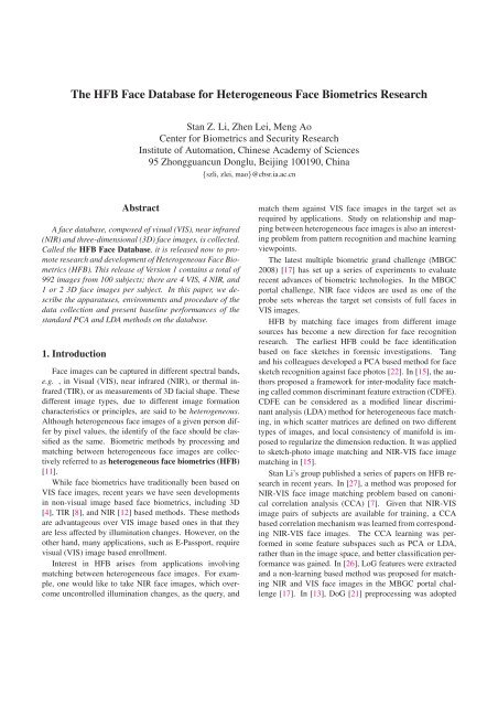
<strong>The</strong> <strong>HFB</strong> <strong>Face</strong> <strong>Database</strong> <strong>for</strong> <strong>Heterogeneous</strong> <strong>Face</strong> <strong>Biometrics</strong> Research<br />
Stan Z. Li, Zhen Lei, Meng Ao<br />
Center <strong>for</strong> <strong>Biometrics</strong> and Security Research<br />
Institute of Automation, Chinese Academy of Sciences<br />
95 Zhongguancun Donglu, Beijing 100190, China<br />
{szli, zlei, mao}@cbsr.ia.ac.cn<br />
Abstract<br />
A face database, composed of visual (VIS), near infrared<br />
(NIR) and three-dimensional (3D) face images, is collected.<br />
Called the <strong>HFB</strong> <strong>Face</strong> <strong>Database</strong>, it is released now to promote<br />
research and development of <strong>Heterogeneous</strong> <strong>Face</strong> <strong>Biometrics</strong><br />
(<strong>HFB</strong>). This release of Version 1 contains a total of<br />
992 images from 100 subjects; there are 4 VIS, 4 NIR, and<br />
1 or 2 3D face images per subject. In this paper, we describe<br />
the apparatuses, environments and procedure of the<br />
data collection and present baseline per<strong>for</strong>mances of the<br />
standard PCA and LDA methods on the database.<br />
1. Introduction<br />
<strong>Face</strong> images can be captured in different spectral bands,<br />
e.g. , in Visual (VIS), near infrared (NIR), or thermal infrared<br />
(TIR), or as measurements of 3D facial shape. <strong>The</strong>se<br />
different image types, due to different image <strong>for</strong>mation<br />
characteristics or principles, are said to be heterogeneous.<br />
Although heterogeneous face images of a given person differ<br />
by pixel values, the identify of the face should be classified<br />
as the same. Biometric methods by processing and<br />
matching between heterogeneous face images are collectively<br />
referred to as heterogeneous face biometrics (<strong>HFB</strong>)<br />
[11].<br />
While face biometrics have traditionally been based on<br />
VIS face images, recent years we have seen developments<br />
in non-visual image based face biometrics, including 3D<br />
[4], TIR [8], and NIR [12] based methods. <strong>The</strong>se methods<br />
are advantageous over VIS image based ones in that they<br />
are less affected by illumination changes. However, on the<br />
other hand, many applications, such as E-Passport, require<br />
visual (VIS) image based enrollment.<br />
Interest in <strong>HFB</strong> arises from applications involving<br />
matching between heterogeneous face images. For example,<br />
one would like to take NIR face images, which overcome<br />
uncontrolled illumination changes, as the query, and<br />
match them against VIS face images in the target set as<br />
required by applications. Study on relationship and mapping<br />
between heterogeneous face images is also an interesting<br />
problem from pattern recognition and machine learning<br />
viewpoints.<br />
<strong>The</strong> latest multiple biometric grand challenge (MBGC<br />
2008) [17] has set up a series of experiments to evaluate<br />
recent advances of biometric technologies. In the MBGC<br />
portal challenge, NIR face videos are used as one of the<br />
probe sets whereas the target set consists of full faces in<br />
VIS images.<br />
<strong>HFB</strong> by matching face images from different image<br />
sources has become a new direction <strong>for</strong> face recognition<br />
research. <strong>The</strong> earliest <strong>HFB</strong> could be face identification<br />
based on face sketches in <strong>for</strong>ensic investigations. Tang<br />
and his colleagues developed a PCA based method <strong>for</strong> face<br />
sketch recognition against face photos [22]. In [15], the authors<br />
proposed a framework <strong>for</strong> inter-modality face matching<br />
called common discriminant feature extraction (CDFE).<br />
CDFE can be considered as a modified linear discriminant<br />
analysis (LDA) method <strong>for</strong> heterogeneous face matching,<br />
in which scatter matrices are defined on two different<br />
types of images, and local consistency of manifold is imposed<br />
to regularize the dimension reduction. It was applied<br />
to sketch-photo image matching and NIR-VIS face image<br />
matching in [15].<br />
Stan Li’s group published a series of papers on <strong>HFB</strong> research<br />
in recent years. In [27], a method was proposed <strong>for</strong><br />
NIR-VIS face image matching problem based on canonical<br />
correlation analysis (CCA) [7]. Given that NIR-VIS<br />
image pairs of subjects are available <strong>for</strong> training, a CCA<br />
based correlation mechanism was learned from corresponding<br />
NIR-VIS face images. <strong>The</strong> CCA learning was per<strong>for</strong>med<br />
in some feature subspaces such as PCA or LDA,<br />
rather than in the image space, and better classification per<strong>for</strong>mance<br />
was gained. In [26], LoG features were extracted<br />
and a non-learning based method was proposed <strong>for</strong> matching<br />
NIR and VIS face images in the MBGC portal challenge<br />
[17]. In [13], DoG [21] preprocessing was adopted
to alleviate the differences of NIR and VIS images, and R-<br />
LDA [16] combined with MB-LBP features [14] was then<br />
utilized to derive the most discriminant subspace. In [10],<br />
a coupled spectral regression framework was proposed to<br />
match between NIR and VIS face images. In [9], a CCA<br />
based regression method, that worked in NIR and 3D tensor<br />
spaces, was proposed to recover 3D face shape from a single<br />
NIR face image. In [25], a regularized kernel CCA and<br />
patch strategy was proposed to learn relationship between<br />
VIS and 3D face images. In [24], an analysis-by-synthesis<br />
method is developed to trans<strong>for</strong>m an NIR face query image<br />
to its VIS counterparts, and then compared to the target<br />
template VIS face images.<br />
In this paper, we describe a face database, called the<br />
“<strong>HFB</strong> <strong>Face</strong> <strong>Database</strong>”, <strong>for</strong> <strong>HFB</strong> research. Visual (VIS),<br />
near infrared (NIR) and three-dimensional (3D) face images<br />
are collected. <strong>The</strong> <strong>HFB</strong> <strong>Face</strong> <strong>Database</strong> is produced<br />
and released to promote and advance <strong>HFB</strong> research and development.<br />
This release of Version 1 contains a total of 992<br />
images from 100 subjects. For every subjects, there are 4<br />
VIS, 4 NIR, and 1 or 2 3D face images. We present the<br />
the baseline per<strong>for</strong>mances of the standard PCA and LDA<br />
methods <strong>for</strong> the database.<br />
Several face databases have been existing, including VIS<br />
databases such as AT&T [1], CMU [20], FERET [19],<br />
FRGC [18] etc., CBSR NIR database [5], and 3D databases<br />
like FRAV3D [6], BJUT-3D [3] and so on. <strong>The</strong> <strong>HFB</strong><br />
database described in this paper will add a new dimension<br />
in face recognition research.<br />
In the rest of the paper, Section 2 introduces the devices<br />
used to collect different modalities of faces. Section 3 and 4<br />
depict the collection procedure and content of the database.<br />
<strong>The</strong> baseline per<strong>for</strong>mances with different experiment configurations<br />
are presented in Section 5.<br />
2. Data Acquisition Setup<br />
Figure 1. <strong>The</strong> VIS camera and the capture environment.<br />
2.2. NIR face images<br />
<strong>The</strong> NIR images are captured by a home-brew device<br />
[12]. In order to obtain good quality NIR image, two strategies<br />
are designed to control the light direction: (1) mount<br />
active lights on the camera to provide frontal lighting, (2)<br />
minimize environmental lighting. We set two requirements<br />
on the active lighting: (1) the lights should be strong enough<br />
to produce a clear frontal-lighted face image without causing<br />
disturbance to human eyes, and (2) the minimization of<br />
the environmental lighting should have minimum reduction<br />
of the intended active lighting.<br />
We use NIR light-emitting diodes (LEDs) of 850nm as<br />
the active lighting source, which are strong enough <strong>for</strong> indoor<br />
use and are power-effective. Such NIR lights are almost<br />
invisible to human eyes, yet most CCD and CMOS<br />
sensors have sufficient response at this spectrum point.<br />
When mounted on the camera, the LEDs are approximately<br />
co-axial to the camera direction, and thus provide<br />
the best possible straight frontal lighting, better than<br />
mounted anywhere else; moreover, when the LEDs and<br />
camera are together, control of the lights can be more easily<br />
using a circuit in the box. <strong>The</strong> geometric layout of the LEDs<br />
on the camera panel may be carefully designed such that the<br />
illumination on the face is as homogeneous as possible.<br />
This section describes the hardware devices and environments<br />
<strong>for</strong> the collection of the VIS, NIR and 3D face<br />
images.<br />
2.1. Visual <strong>Face</strong> Images<br />
<strong>The</strong> visual color face images are captured using Canon<br />
A640 Camera. <strong>The</strong> image resolution is 640 × 480. <strong>The</strong><br />
camera is fixed on a tripod and the subjects are asked to be<br />
seated on a chair in front of the white background, as shown<br />
in Fig. 1. <strong>The</strong> height of digital camera is adjusted manually<br />
so that the face is in the central part of the image. Four<br />
frontal images with neutral and smile expression (or with<br />
and without glasses) as well as two different distances are<br />
captured.<br />
Figure 2. <strong>The</strong> NIR face camera and the capture environment.<br />
<strong>The</strong> strength of the total LED lighting should be such that<br />
it results in the NIR face images with good S/N ratio when<br />
the camera-face distance is between 80-120 cm, a conve-
nient range <strong>for</strong> the user. A guideline is that it should be as<br />
strong as possible, at least stronger than expected environmental<br />
illumination, yet does not cause sensor saturation.<br />
A concern is the safety to human eyes. When the sensor<br />
working in the normal mode is not saturated, the safety is<br />
guaranteed.<br />
Our solution <strong>for</strong> requirement (2) above is to use a long<br />
pass optical filter to cut off visible light while allowing NIR<br />
light to pass. We choose a filter such that ray passing rates<br />
are 0%, 50%, 88%, and 99% at the wavelength points of<br />
720, 800, 850, and 880nm, respectively. <strong>The</strong> filter cuts<br />
off visible environmental lights (< 700nm) while allowing<br />
most of the 850nm NIR light to pass.<br />
Fig. 2 illustrates the hardware device and its relationship<br />
with the face. <strong>The</strong> device consists of 18 NIR LEDs, an NIR<br />
camera, and the box. <strong>The</strong> NIR LEDs and camera are <strong>for</strong><br />
NIR face image acquisition. <strong>The</strong> hardware and the face are<br />
relatively positioned in a way that the lighting is frontal and<br />
NIR rays provide nearly homogenous illumination on face.<br />
<strong>The</strong> imaging hardware works at a rate of 30 frames per second<br />
with the USB 2.0 protocol <strong>for</strong> 640 × 480 images.<br />
<strong>The</strong> NIR imaging device used in this paper is a standard<br />
version <strong>for</strong> indoor use and under fluorescent lighting. For<br />
use in conditions with significant NIR components, it would<br />
require an enhanced version. <strong>The</strong> enhanced version developed<br />
in [28] provides clear face images even under sunlight.<br />
<strong>The</strong> subjects are seated on a chair facing the NIR capture<br />
device. Subjects are asked to change their expression<br />
and move near and far from the camera. <strong>The</strong> NIR device<br />
captures a series of images of the process and we finally<br />
select four images with different expressions and poses.<br />
2.3. 3D <strong>Face</strong> Images<br />
<strong>The</strong> 3D faces are acquired using a Minolta vivid 910<br />
laser scanner, as shown in Fig. 3. <strong>The</strong> laser scanner provides<br />
the depth (z-direction) <strong>for</strong> every point in the visible<br />
(x,y) plane of the faces. <strong>The</strong> background color is set to be<br />
black in order to absorb the laser better to reduce the noise<br />
of the captured data.<br />
<strong>The</strong> process of 3D face acquisition takes about 3 seconds<br />
per scan. <strong>The</strong> subjects are asked to tidy their hair so as not<br />
to block the eyebrows and eyes, and keep still during the<br />
acquisition process. For most subjects, two 3D faces with<br />
different distances are acquired.<br />
Figure 3. 3D face capture device and environment. Subjects are<br />
seated in front of black background and scanned by Minolta vivid<br />
910 laser scanner.<br />
This release of <strong>HFB</strong> database Ver.1 includes the following:<br />
1. <strong>The</strong> raw images, including (1) the VIS and (2) the NIR<br />
images of size 640 × 480 in the JPEG <strong>for</strong>mat, and (3)<br />
the 3D faces with wrl <strong>for</strong>mat;<br />
2. <strong>The</strong> processed 3D faces: <strong>Face</strong> regions not belonging<br />
to the face are discarded and then the 3D data is processed<br />
by removing high noise and filling holes using<br />
an interpolation algorithm. Finally, the 3D points are<br />
sampled to <strong>for</strong>m the depth images. <strong>The</strong> sizes vary from<br />
image to image.<br />
3. <strong>The</strong> eye coordinates of the VIS, NIR and 3D depth images,<br />
manually labeled.<br />
4. Cropped versions of the raw VIS, NIR and depth images.<br />
<strong>The</strong> crop was made in two sizes, 32 × 32 and<br />
128 × 128, and is done based on the eye coordinates.<br />
Some samples are shown in Figs. 4 and 5. <strong>The</strong> cropped<br />
VIS, NIR and depth faces are used <strong>for</strong> baseline experiments<br />
(see the next section). <strong>The</strong> download website is<br />
http://www.cbsr.ia.ac.cn/english/<strong>Database</strong>s.asp.<br />
3. <strong>Database</strong> Description<br />
Thus, the <strong>HFB</strong> face database consists of 100 subjects in<br />
total, including 57 males and 43 females. <strong>The</strong>re are 4 VIS<br />
and 4 NIR face images per subject. For the 3D faces, there<br />
are 2 face images per subject <strong>for</strong> 92 subjects and 1 per subject<br />
<strong>for</strong> the other 8 subjects. Fig. 4 shows some face image<br />
examples.<br />
Figure 5. Cropped face examples of VIS (1st row), NIR (2nd row)<br />
and 3D depth faces (3rd row).
Figure 4. VIS, NIR and 3D raw data from one subject.<br />
4. Baseline Results<br />
<strong>The</strong> standard PCA [23] and LDA [2] are used as the baseline<br />
methods. Six experiments, explained in table 1, are designed<br />
to obtain the baseline per<strong>for</strong>mance on the cropped<br />
VIS, NIR and 3D depth images.<br />
Table 1. Configurations of six experiments.<br />
Exp.1 Exp.2 Exp.3 Exp.4 Exp.5 Exp.6<br />
Gallery VIS NIR VIS 3D NIR 3D<br />
Probe NIR VIS 3D VIS 3D NIR<br />
Two protocols are designed to test the baseline per<strong>for</strong>mances<br />
<strong>for</strong> every of the six experiments. In protocol I, 2<br />
VIS and 2 NIR images are selected per subject, and this<br />
<strong>for</strong>ms the training set; and the remaining 2 VIS and 2 NIR<br />
images are used <strong>for</strong> the test set. For 3D faces, <strong>for</strong> the subjects<br />
containing two images, 1 is selected <strong>for</strong> training and<br />
the other is used <strong>for</strong> testing. For the subjects containing<br />
only 1 image, the image is selected <strong>for</strong> testing. <strong>The</strong>re is no<br />
overlapping in images between training and testing set. In<br />
protocol II, the images of the first 70 subjects are selected<br />
to <strong>for</strong>m the training set, and the images of the last 30 subjects<br />
are used as the testing set. <strong>The</strong>re is no overlapping in<br />
subjects between training and testing sets.<br />
For the PCA method, the dimension of subspace is retained<br />
by preserving the 98% of the total energy. Table 2 illustrates<br />
the reduced PCA dimensions <strong>for</strong> the experiments.<br />
For the LDA method, more specifically, the Fisher-LDA<br />
method [2], PCA is first per<strong>for</strong>med to make the with-in<br />
class scatter matrix non-singular, giving a subspace of dimensionality<br />
of sample num minus class num; LDA is then<br />
applied on the reduced subspace to find the final c − 1 LDA<br />
dimensions, where c is the class number. <strong>The</strong>re<strong>for</strong>e, the final<br />
dimensionality of the LDA feature is 99 and 69 <strong>for</strong> the<br />
experiments in Protocol I and Protocol II, respectively. In
the testing phase, the cosine distance is adopted to evaluate<br />
the similarity of different samples and the maximum correlation<br />
criterion is used <strong>for</strong> the classification.<br />
Table 2. Reduced dimension of PCA <strong>for</strong> different experiments.<br />
Protocol I Protocol II<br />
32x32 128x128 32x32 128x128<br />
Exp.1&Exp.2 75 149 78 175<br />
Exp.3&Exp.4 51 92 46 93<br />
Exp.5&Exp.6 43 84 49 103<br />
Tables 3 and 4 show the rank-1 recognition rates <strong>for</strong> six<br />
experiments following protocol I and II with two size images<br />
respectively and Figs. 6 and 7 illustrate the corresponding<br />
cumulative match curves.<br />
We have the following conclusions <strong>for</strong> the baseline per<strong>for</strong>mances:<br />
1. For the <strong>HFB</strong> problems in the baseline experiments, the<br />
unsupervised method of the PCA per<strong>for</strong>med poorly.<br />
Comparatively, the supervised method of the Fisher-<br />
LDA per<strong>for</strong>med much better.<br />
2. For the LDA, the per<strong>for</strong>mance of protocol I was much<br />
better than that of protocol II, due to the fact that the<br />
subjects are all seen in both training and testing sets.<br />
However, Protocol II is often more relevant to practical<br />
situations in applications. <strong>The</strong> ability to generalize is a<br />
great challenge in <strong>HFB</strong>.<br />
3. Among the six experiments, the results of Exp. 1 and<br />
Exp. 2 were better than others. That was because the<br />
imaging <strong>for</strong>mation principles are relatively similar <strong>for</strong><br />
VIS and NIR images, but are completely different from<br />
that of 3D depth imaging.<br />
4. In summary, the baseline per<strong>for</strong>mance of the <strong>HFB</strong> face<br />
database was relatively poor. Development of effective<br />
methods are needed to create high per<strong>for</strong>mance <strong>HFB</strong><br />
algorithms .<br />
5. Conclusions<br />
In this paper, we introduced the <strong>HFB</strong> face database of<br />
VIS-NIR-3D face images <strong>for</strong> <strong>HFB</strong> research. <strong>The</strong> imaging<br />
devices, environments and acquisition procedures are described.<br />
Six experiments designed <strong>for</strong> the baseline per<strong>for</strong>mances<br />
on the database are presented. In the future, we will<br />
collect more face images in several sessions, to provide time<br />
elapse variations and to enlarge the <strong>HFB</strong> database.<br />
Acknowledgements<br />
This work was supported by the following funding<br />
resources: National Natural Science Foundation Project<br />
#60518002, National Science and Technology Support Program<br />
Project #2006BAK08B06, National Hi-Tech (863)<br />
Program Projects #2006AA01Z192, #2006AA01Z193, and<br />
#2008AA01Z124, Chinese Academy of Sciences 100 people<br />
project, and AuthenMetric R&D Funds.<br />
References<br />
[1] AT&T <strong>Database</strong>. http://www.cl.cam.ac.uk/research/dtg/<br />
attarchive/facedatabase.html. 2<br />
[2] P. Belhumeur, J. Hespanha, and D. Kriegman. Eigenfaces vs.<br />
fisherfaces: recognition using class specific linear projection.<br />
IEEE Transactions on Pattern Analysis and Machine Intelligence,<br />
19(7):711–720, 1997. 4<br />
[3] BJUT-3D <strong>Database</strong>. http://www.bjpu.edu.cn/sci/multimedia/<br />
mul-lab/3dface/facedatabase.htm. 2<br />
[4] K. W. Bowyer, Chang, and P. J. Flynn. A survey of 3D and<br />
multi-modal 3d+2d face recognition. In Proceedings of International<br />
Conference on Pattern Recognition, pages 358–<br />
361, August 2004. 1<br />
[5] CBSR NIR <strong>Face</strong> Dataset. http://www.cse.ohiostate.edu/otcbvs-bench/.<br />
2<br />
[6] FRAV3D <strong>Database</strong>. http://www.frav.es/databases/FRAV3d/.<br />
2<br />
[7] H. Hotelling. Relations between two sets of variates.<br />
Biometrika, 28:321–377, 1936. 1<br />
[8] S. G. Kong, J. Heo, B. Abidi, J. Paik, and M. Abidi. Recent<br />
advances in visual and infrared face recognition - A review.<br />
Computer Vision and Image Understanding, 97(1):103–135,<br />
January 2005. 1<br />
[9] Z. Lei, Q. Bai, R. He, and S. Z. Li. <strong>Face</strong> shape recovery from<br />
a single image using cca mapping between tensor spaces. In<br />
Proceedings of IEEE Computer Society Conference on Computer<br />
Vision and Pattern Recognition, pages 1–7, 2008. 2<br />
[10] Z. Lei, S. Liao, and S. Z. Li. Coupled spectral regressoin<br />
<strong>for</strong> matching heterogeneous faces. In Proceedings of IEEE<br />
Computer Society Conference on Computer Vision and Pattern<br />
Recognition, 2009. 2<br />
[11] S. Z. Li. <strong>Heterogeneous</strong> face biometrics. In S. Z. Li, editor,<br />
Encyclopedia of <strong>Biometrics</strong>. Springer, 2009. 1<br />
[12] S. Z. Li, R. Chu, S. Liao, and L. Zhang. Illumination invariant<br />
face recognition using near-infrared images. IEEE<br />
Transactions on Pattern Analysis and Machine Intelligence,<br />
29(4):627–639, April 2007. 1, 2<br />
[13] S. Liao, D. Yi, Z. Lei, R. Qin, and S. Z. Li. <strong>Heterogeneous</strong><br />
face recognition from local structures of normalized appearance.<br />
In Proceedings of IAPR/IEEE International Conference<br />
on <strong>Biometrics</strong>, 2009. 1<br />
[14] S. Liao, X. Zhu, Z. Lei, L. Zhang, and S. Z. Li. Learning<br />
multi-scale block local binary patterns <strong>for</strong> face recognition.<br />
In Proceedings of IAPR/IEEE International Conference on<br />
<strong>Biometrics</strong>, pages 828–837, 2007. 2
Table 3. Rank-1 recognition rates <strong>for</strong> Protocol I.<br />
Methods Exp.1 Exp.2 Exp.3 Exp.4 Exp.5 Exp.6<br />
PCA-32 0.0550 0.0950 0.0200 0.0200 0.0100 0.0150<br />
PCA-128 0.0600 0.1050 0.0200 0.0200 0.0100 0.0100<br />
LDA-32 0.7700 0.8350 0.3300 0.4700 0.4600 0.4150<br />
LDA-128 0.8050 0.8550 0.2400 0.3950 0.3300 0.3400<br />
Table 4. Rank-1 recognition rates <strong>for</strong> Protocol II.<br />
Methods Exp.1 Exp.2 Exp.3 Exp.4 Exp.5 Exp.6<br />
PCA-32 0.0667 0.0667 0.0351 0.0333 0.1228 0.0750<br />
PCA-128 0.0667 0.0667 0.0175 0.0333 0.1228 0.0667<br />
LDA-32 0.2750 0.3167 0.1228 0.2500 0.2632 0.2250<br />
LDA-128 0.3083 0.4500 0.2982 0.2333 0.2632 0.2167<br />
[15] D. Lin and X. Tang. Inter-modality face recognition. In Proceedings<br />
of the European Conference on Computer Vision,<br />
pages 13–26, 2006. 1<br />
[16] J. Lu, K. N. Plataniotis, and A. N. Venetsanopoulos. Regularization<br />
studies on lda <strong>for</strong> face recognition. In Proceedings of<br />
IEEE International Conference on Image Processing, pages<br />
63–66, 2004. 2<br />
[17] MBGC 2008. http://face.nist.gov/mbgc/. 1<br />
[18] P. J. Phillips, P. J. Flynn, W. T. Scruggs, K. W. Bowyer,<br />
J. Chang, K. Hoffman, J. Marques, J. Min, and W. J. Worek.<br />
Overview of the face recognition grand challenge. In Proceedings<br />
of IEEE Computer Society Conference on Computer<br />
Vision and Pattern Recognition, pages 947–954, 2005.<br />
2<br />
[19] P. J. Phillips, H. Moon, S. A. Rizvi, and P. J. Rauss. <strong>The</strong><br />
FERET evaluation methodology <strong>for</strong> face-recognition algorithms.<br />
IEEE Transactions on Pattern Analysis and Machine<br />
Intelligence, 22(10):1090–1104, 2000. 2<br />
[20] T. Sim, S. Baker, and M. Bsat. <strong>The</strong> CMU pose, illumination,<br />
and expression database. IEEE Transactions on Pattern<br />
Analysis and Machine Intelligence, 25(12):1615–1618,<br />
2003. 2<br />
[21] X. Tan and B. Triggs. Enhanced local texture feature sets<br />
<strong>for</strong> face recognition under difficult lighting conditions. In<br />
Proceedings of the IEEE International Workshop on Analysis<br />
and Modeling of <strong>Face</strong>s and Gestures, 2007. 1<br />
[22] X. Tang and X. Wang. <strong>Face</strong> sketch recognition. IEEE<br />
Transactions on Circuits and Systems <strong>for</strong> Video Technology,<br />
14(1):50–57, 2004. 1<br />
[23] M. A. Turk and A. P. Pentland. <strong>Face</strong> recognition using eigenfaces.<br />
In Proceedings of IEEE Computer Society Conference<br />
on Computer Vision and Pattern Recognition, pages 586–<br />
591, Hawaii, June 1991. 4<br />
[24] R. Wang, J. Yang, D. Yi, and S. Z. Li. An analysis-bysynthesis<br />
method <strong>for</strong> heterogeneous face biometrics. In Proceedings<br />
of IAPR/IEEE International Conference on <strong>Biometrics</strong>,<br />
2009. 2<br />
[25] W. Yang, D. Yi, Z. Lei, J. Sang, and S. Z. Li. 2d-3d face<br />
matching using cca. In Proc. IEEE International Conference<br />
on Automatic <strong>Face</strong> and Gesture Recognition, 2008. 2<br />
[26] D. Yi, S. Liao, Z. Lei, J. Sang, and S. Z. Li. Partial face<br />
matching between near infrared and visual images in mbgc<br />
portal challenge. In Proceedings of IAPR/IEEE International<br />
Conference on <strong>Biometrics</strong>, 2009. 1<br />
[27] D. Yi, R. Liu, R. Chu, Z. Lei, and S. Z. Li. <strong>Face</strong> matching<br />
between near infrared and visible light images. In Proceedings<br />
of IAPR/IEEE International Conference on <strong>Biometrics</strong>,<br />
pages 523–530, 2007. 1<br />
[28] D. Yi, R. Liu, R. Chu, R. Wang, D. Liu, and S. Z. Li. Outdoor<br />
face recognition using enhanced near infrared imaging.<br />
In Proceedings of IAPR/IEEE International Conference on<br />
<strong>Biometrics</strong>, pages 415–423, 2007. 3
1<br />
1<br />
0.9<br />
0.9<br />
0.8<br />
0.8<br />
Cumulative Match Score<br />
0.7<br />
0.6<br />
0.5<br />
0.4<br />
0.3<br />
0.2<br />
0.1<br />
0<br />
PCA−32<br />
PCA−128<br />
LDA−32<br />
LDA−128<br />
5 10 15 20 25 30 35 40<br />
Rank<br />
Cumulative Match Score<br />
0.7<br />
0.6<br />
0.5<br />
0.4<br />
0.3<br />
0.2<br />
0.1<br />
0<br />
PCA−32<br />
PCA−128<br />
LDA−32<br />
LDA−128<br />
5 10 15 20 25 30 35 40<br />
Rank<br />
Exp. 1 (VIS-NIR)<br />
Exp. 2 (NIR-VIS)<br />
1<br />
1<br />
0.9<br />
0.9<br />
0.8<br />
0.8<br />
Cumulative Match Score<br />
0.7<br />
0.6<br />
0.5<br />
0.4<br />
0.3<br />
0.2<br />
0.1<br />
0<br />
PCA−32<br />
PCA−128<br />
LDA−32<br />
LDA−128<br />
5 10 15 20 25 30 35 40<br />
Rank<br />
Cumulative Match Score<br />
0.7<br />
0.6<br />
0.5<br />
0.4<br />
0.3<br />
0.2<br />
0.1<br />
0<br />
PCA−32<br />
PCA−128<br />
LDA−32<br />
LDA−128<br />
5 10 15 20 25 30 35 40<br />
Rank<br />
Exp. 3 (VIS-3D)<br />
Exp. 4 (3D-VIS)<br />
1<br />
1<br />
0.9<br />
0.9<br />
0.8<br />
0.8<br />
Cumulative Match Score<br />
0.7<br />
0.6<br />
0.5<br />
0.4<br />
0.3<br />
0.2<br />
0.1<br />
0<br />
PCA−32<br />
PCA−128<br />
LDA−32<br />
LDA−128<br />
5 10 15 20 25 30 35 40<br />
Rank<br />
Cumulative Match Score<br />
0.7<br />
0.6<br />
0.5<br />
0.4<br />
0.3<br />
0.2<br />
0.1<br />
0<br />
PCA−32<br />
PCA−128<br />
LDA−32<br />
LDA−128<br />
5 10 15 20 25 30 35 40<br />
Rank<br />
Exp. 5 (NIR-3D)<br />
Exp. 6 (3D-NIR)<br />
Figure 6. Cumulative match curves <strong>for</strong> protocol I.
1<br />
1<br />
0.9<br />
0.9<br />
0.8<br />
0.8<br />
Cumulative Match Score<br />
0.7<br />
0.6<br />
0.5<br />
0.4<br />
0.3<br />
0.2<br />
0.1<br />
PCA−32<br />
PCA−128<br />
LDA−32<br />
LDA−128<br />
Cumulative Match Score<br />
0.7<br />
0.6<br />
0.5<br />
0.4<br />
0.3<br />
0.2<br />
0.1<br />
PCA−32<br />
PCA−128<br />
LDA−32<br />
LDA−128<br />
0<br />
5 10 15 20 25 30 35 40<br />
Rank<br />
0<br />
5 10 15 20 25 30 35 40<br />
Rank<br />
Exp. 1 (VIS-NIR)<br />
Exp. 2 (NIR-VIS)<br />
1<br />
1<br />
0.9<br />
0.9<br />
0.8<br />
0.8<br />
Cumulative Match Score<br />
0.7<br />
0.6<br />
0.5<br />
0.4<br />
0.3<br />
0.2<br />
0.1<br />
PCA−32<br />
PCA−128<br />
LDA−32<br />
LDA−128<br />
Cumulative Match Score<br />
0.7<br />
0.6<br />
0.5<br />
0.4<br />
0.3<br />
0.2<br />
0.1<br />
PCA−32<br />
PCA−128<br />
LDA−32<br />
LDA−128<br />
0<br />
5 10 15 20 25 30 35 40<br />
Rank<br />
0<br />
5 10 15 20 25 30 35 40<br />
Rank<br />
Exp. 3 (VIS-3D)<br />
Exp. 4 (3D-VIS)<br />
1<br />
1<br />
0.9<br />
0.9<br />
Cumulative Match Score<br />
0.8<br />
0.7<br />
0.6<br />
0.5<br />
0.4<br />
0.3<br />
0.2<br />
0.1<br />
PCA−32<br />
PCA−128<br />
LDA−32<br />
LDA−128<br />
Cumulative Match Score<br />
0.8<br />
0.7<br />
0.6<br />
0.5<br />
0.4<br />
0.3<br />
0.2<br />
0.1<br />
PCA−32<br />
PCA−128<br />
LDA−32<br />
LDA−128<br />
0<br />
5 10 15 20 25 30 35 40<br />
Rank<br />
0<br />
5 10 15 20 25 30 35 40<br />
Rank<br />
Exp. 5 (NIR-3D)<br />
Exp. 6 (3D-NIR)<br />
Figure 7. Cumulative match curves <strong>for</strong> protocol II.