Synchronous Serial IO Serial Peripheral Interface (SPI) Multi ...
Synchronous Serial IO Serial Peripheral Interface (SPI) Multi ...
Synchronous Serial IO Serial Peripheral Interface (SPI) Multi ...

Create successful ePaper yourself
Turn your PDF publications into a flip-book with our unique Google optimized e-Paper software.
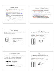
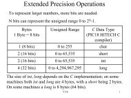
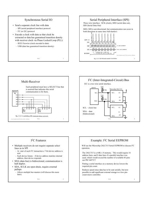
<strong>Synchronous</strong> <strong>Serial</strong> <strong>IO</strong><br />
• Send a separate clock line with data<br />
– <strong>SPI</strong> (serial peripheral interface) protocol<br />
–I 2 C (or I2C) protocol<br />
• Encode a clock with data so that clock be<br />
extracted or data has guaranteed transition density<br />
with receiver clock via Phase-Locked-Loop (PLL)<br />
– IEEE Firewire (clock encoded in data)<br />
– USB (data has guaranteed transition density)<br />
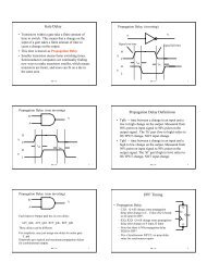
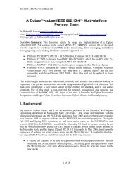
<strong>Serial</strong> <strong>Peripheral</strong> <strong>Interface</strong> (<strong>SPI</strong>)<br />
Three wire interface: SCK (clock), SDO (serial data out),<br />
SDI (<strong>Serial</strong> Data Out)<br />
SDO, SDI is uni-directional, but communication can occur in<br />
both directions at same time (full-duplex).<br />
From: The Quintessential PIC Microcontroller, Sid Katzen<br />
V 0.1 1<br />
V 0.1 2<br />
<strong>Multi</strong>-Receiver<br />
Each peripheral must have a SELECT line that<br />
is asserted that indicates this serial<br />
communication is for them.<br />
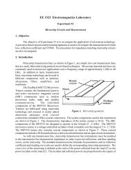
I 2 C (Inter-Integrated-Circuit) Bus<br />
I2C is a two wire serial interface.<br />
16F873<br />
Vdd<br />
10K<br />
Microchip 24LC515<br />
SCL<br />
SCL A2<br />
Vdd<br />
SDA<br />
10K<br />
SDA<br />
A1<br />
A0<br />
SCL – clock line<br />
SDA – data<br />
(bidirectional)<br />
SCL<br />
SDA<br />
A2<br />
A1<br />
A0<br />
From: The Quintessential PIC Microcontroller, Sid Katzen V 0.1 3<br />
V 0.1 4<br />
I 2 C Features<br />
• <strong>Multi</strong>ple receivers do not require separate select<br />
lines as in <strong>SPI</strong><br />
– At start of each I 2 C transaction a 7-bit device address is<br />
sent<br />
– Each device listens – if device address matches internal<br />
address, then device responds<br />
• SDA (data line) is bidirectional, communication is<br />
half duplex<br />
• SDA, SCLK are open-drain, require external<br />
pullups<br />
– Allows multiple bus masters (will discuss this more<br />
later).<br />
Example: I 2 C <strong>Serial</strong> EEPROM<br />
Will use the Microchip 24LC515 <strong>Serial</strong> EEPROM to discuss I 2 C<br />
operation.<br />
The 24LC515 is a 64K x 8 memory. This would require 16<br />
address lines, and 8 data lines if a parallel interface was<br />
used, which would exceed the number of available <strong>IO</strong> pins<br />
our PIC16873!!!<br />
Putting a serial interface on a memory device lowers the<br />
required pin count.<br />
Reduces speed since data has to be sent serially, but now<br />
possible to add significant external storage to a low pincount<br />
micro controller.<br />
V 0.1 5<br />
V 0.1 6
I 2 C Device Addressing<br />
Each I2C device has either a 7-bit or 10-bit device address.<br />
We will use an I2C EEPROM and an I2C DAC (Digital-to-<br />
Analog Converter, MAX517) in lab. Both of these devices<br />
have a 7-bit address.<br />
Upper four bits are assigned by device manufacturer and are<br />
hardcoded in the device. Lower three bits are used in<br />
different ways by manufacturer.<br />
Microchip 24LC515 LC515 control byte (contains slave address):<br />
SCL A2<br />
7 6 5 4 3 2 1 0 R/W = 1<br />
for read, 0<br />
A1<br />
1 0 1 0 B0 A1 A0 R/W for write.<br />
SDA A0 ‘B0’ is block select (upper/lower 32K). A1, A0<br />
are chip selects, four devices on one bus.<br />
V 0.1 7<br />
IDLE: SCL,<br />
SDA high.<br />
START: high<br />
to low<br />
transition on<br />
SDA while<br />
SCL high.<br />
Valid data:<br />
While clock is<br />
high, data<br />
valid and<br />
stable.<br />
I2C Transmission<br />
Data<br />
changes<br />
while<br />
clock is<br />
low.<br />
STOP: low to<br />
high transition<br />
on SDA while<br />
SCL high.<br />
V 0.1 8<br />
Acknowledgement<br />
ACK sent by slave after every 8-bits received. Master releases line<br />
(stops driving), samples line on next clock.<br />
Slave MUST pull line low. If Master does not detect ACK, then<br />
sets error bit. If Slave does not pull line low, the pullup resistors<br />
will pull the line low.<br />
Most common cause of ACK error – incorrect device address.<br />
Byte Write Operation<br />
• Byte Write: used to write one byte<br />
– Send Control Byte, High address byte, low address<br />
byte, data.<br />
– After data is sent, takes 5 ms for write to complete<br />
– SLOOOOOWWWWWW....<br />
V 0.1 9<br />
‘0’ indicates write mode.<br />
‘X’ because block select bit<br />
chooses high or low 32K.<br />
V 0.1 10<br />
Page Write Operation<br />
• Send a block of 64 bytes, then perform write<br />
– Send starting address, followed by 64 bytes<br />
– After 64 bytes sent, wait 5 ms for write to complete<br />
– Much faster than individual writes<br />
Address must be on a page boundary. For page size = 64 = 0x40,<br />
starting address must be a multiple of 64.<br />
V 0.1 11<br />
Speed Comparison<br />
• Assume a 400 Khz I 2 C bus, 2.5 us clock period<br />
(2.5 e-6)<br />
• Random write:<br />
– 9 bit transmission = 2.5 us * 9 = 22.5 us<br />
– 5 ms + 22.5 us* 4 (control,addhi,addlo,data) =5.09 ms<br />
– For 64 bytes = 325 ms approximately, not counting software<br />
overhead.<br />
• Page Write<br />
– 67 bytes total (control, addhi, addlo, data)<br />
– 5 ms + 67 * 22.5 us = 6.5 ms!!!<br />
V 0.1 12
Checking for end-ofwrite<br />
Timing on write is<br />
guaranteed to finish after 5<br />
ms. But can end sooner; to<br />
determine if write finished<br />
use polling method.<br />
No ACK means device is<br />
still busy with last write.<br />
V 0.1 13<br />
Read Operation: Current Address<br />
• An internal counter is used to keep track of last<br />
address used<br />
• A current address read uses this address, only<br />
sends the command byte<br />
– Internal counter incremented after read operation<br />
‘1’ indicates read<br />
operation<br />
‘no ack’ because slave is<br />
driving data back to<br />
master.<br />
V 0.1 14<br />
Random Read Operation<br />
• Must first set the internal address counter by<br />
starting a write operation, but aborting by not<br />
sending data byte<br />
Sequential Read<br />
• Like a current address read, but after Slave sends<br />
data byte, Master sends ACK instead of STOP<br />
– Slave then sends next byte<br />
– Can do this from 0x0000h to 0x7FFF (lower 32K block). When<br />
0x7FFF is reached, address rolls over to 0x0000<br />
– Upper block goes from 0x8000 to 0xFFFF; at 0xFFFF address<br />
rolls over to 0x8000<br />
– Internal address counter is only 15 bits wide.<br />
Aborted random write (address only,<br />
no data)<br />
Current address read<br />
V 0.1 15<br />
V 0.1 16<br />
PIC 16 I 2 C Registers<br />
• <strong>Synchronous</strong> <strong>Serial</strong> Port on PIC implements I2C<br />
• Registers are:<br />
– SSPCON – control register - we will always set this to<br />
0x28 which enables I2C MASTER mode.<br />
– SSPCON1 – control register - used to initiate a<br />
START/STOP conditions, indicates if ACK has been<br />
received<br />
– SSPSTAT – status register – check this to see if byte<br />
finished transmitting, or byte has been received<br />
– SSPBUF – read/write to this register for data transfer<br />
– SSPADD – used to control clock rate<br />
I 2 C on the PIC16<br />
• Will always use master mode on the PIC16<br />
– This means that the PIC will always initiate all I 2 C bus<br />
activity<br />
• To set I2C clock rate, write 8-bit value to the<br />
SPADD register<br />
– Clock rate = Fosc/(4 *(SSPADD+1))<br />
• I 2 C standard defines 100 KHz and 400 KHz but in<br />
reality just about any clock rate from DC to 400<br />
KHz wors<br />
V 0.1 17<br />
V 0.1 18
Lab #8: Read/Write to <strong>Serial</strong> EEPROM<br />
• Lab #8 has you read/write to a <strong>Serial</strong> EEPROM<br />
via the I2C bus<br />
• The files i2cmsu.h, i2cmsu.c define interface<br />
subroutines for the I2C bus<br />
– This file also has subroutines for random read/write,<br />
block read/write for the serial eeprom<br />
• The file memblk.c tests uses the subroutines to<br />
read/write data to the serial EEPROM.<br />
V 0.1 19<br />
i2cmsu.c Subroutines<br />
• i2c_idle() – wait for idle condition on I2C bus<br />
• i2c_Start() – send a START and wait for START<br />
end<br />
• i2c_Stop() – send a STOP and wait for STOP end<br />
• i2c_doAck() – do an ACK cycle<br />
• i2c_doNak() – do a NACK cycle<br />
• i2c_WriteTo(address) – do a i2c_Start(), then send<br />
address to I2C bus.<br />
• i2c_PutByte(byte) – write byte to I2C, wait for<br />
finish, then get an ACK<br />
• i2c_GetByte() – get a byte from I2C bus<br />
V 0.1 20<br />
Random Read: memread(cmd,addr)<br />
i2c_Writeto (write_cmd)<br />
i2c_PutByte (address_hibyte)<br />
i2c_PutByte (address_lobyte)<br />
i2c_Stop()<br />
i2c_Writeto (read_cmd)<br />
i2c_GetByte ()<br />
i2c_Stop()<br />
cmd is unsigned char<br />
that has EEprom i2c<br />
device address<br />
addr is unsigned char is<br />
memory address within<br />
EEprom<br />
Set internal address<br />
counter.<br />
Read byte from<br />
current address<br />
V 0.1 21<br />
memread(cmd,addr)<br />
Does a random read of EEPROM<br />
/* random read */<br />
unsigned char mem_read(unsigned char cmd,int addr) {<br />
unsigned char hbyte, lbyte, val;<br />
if (addr & 0x8000) { // if MSB set , set block select bit<br />
cmd = cmd | 0x08;<br />
}<br />
hbyte = (addr >> 8) & 0x7F; // high address byte<br />
lbyte = (addr) & 0xFF; // low address byte<br />
i2c_WriteTo(cmd); // send write cmd, do this to set address counter<br />
i2c_PutByte(hbyte); // send high address byte<br />
i2c_PutByte(lbyte); // send low address byte<br />
i2c_Stop();<br />
// send stop<br />
cmd = cmd | 0x1; // set read bit<br />
i2c_WriteTo(cmd); // send read cmd, address set by previous cmd<br />
val = i2c_GetByte(); // read data<br />
i2c_Stop();<br />
// send stop<br />
return(val);<br />
}<br />
V 0.1 22<br />
i2c_Writeto (write_cmd)<br />
i2c_PutByte (address_hibyte)<br />
i2c_PutByte (address_lobyte)<br />
i = 0;<br />
i2c_PutByte (); i++<br />
i = 64?<br />
i2c_Stop()<br />
Page Write<br />
set starting<br />
address.<br />
Send 64 bytes.<br />
Page (Block) Write<br />
/* block write */<br />
void block_mem_write(unsigned char cmd,int addr, char *buf) {<br />
unsigned char hbyte, lbyte, val;<br />
hbyte = (addr >> 8) & 0x7F; // high address byte<br />
lbyte = (addr) & 0xFF; // low address byte<br />
i2c_WriteTo(cmd); // send write cmd<br />
i2c_PutByte(hbyte); // send high address byte<br />
i2c_PutByte(lbyte); // send low address byte<br />
for (k=0;k
i2c_Writeto (write_cmd)<br />
i2c_PutByte (address_hibyte)<br />
i2c_PutByte (address_lobyte)<br />
i2c_Stop()<br />
i2c_Writeto (read_cmd)<br />
i2c_GetByte (); i++<br />
i = 64?<br />
yes<br />
i2c_Stop()<br />
no<br />
i2c_doAck();<br />
Block Read<br />
set starting<br />
address.<br />
Send read<br />
command<br />
Use sequential<br />
read to get 64<br />
bytes.<br />
Sequential read can read up<br />
to 32K, block size of 64<br />
bytes was arbitrary<br />
V 0.1 25<br />
Block Read in C<br />
/* block read */<br />
void block_mem_read(unsigned char cmd,int addr,char *buf) {<br />
unsigned char hbyte;<br />
unsigned char lbyte;<br />
unsigned char k;<br />
if (addr & 0x8000) {<br />
// if MSB set , set block select bit<br />
cmd = cmd | 0x08;<br />
}<br />
hbyte = (addr >> 8) & 0x7F; // high address byte<br />
lbyte = (addr) & 0xFF; // low address byte<br />
i2c_WriteTo(cmd); // send write cmd, do this to set address counter<br />
i2c_PutByte(hbyte); // send high address byte<br />
i2c_PutByte(lbyte); // send low address byte<br />
i2c_Stop();<br />
// send stop<br />
cmd = cmd | 0x1; // set read bit<br />
i2c_WriteTo(cmd);<br />
for (k=0;k
i2c_PutByte()<br />
i2c_PutByte(unsigned char byte) {<br />
i2c_idle();<br />
/* write data */<br />
SSPBUF = byte;<br />
/* wait until finished */<br />
while(bittst(SSPSTAT,2));<br />
/* wait for acknowledge */<br />
while(bittst(SSPCON2,6));<br />
}<br />
i2c_FastPutByte deletes this call.<br />
SSPBUF holds<br />
outgoing data<br />
Cleared when<br />
transmit finished.<br />
Cleared when<br />
ACK received.<br />
V 0.1 31<br />
i2c_WriteTo<br />
i2c_WriteTo(unsigned char addr) {<br />
/* first, send start */<br />
i2c_Start();<br />
SSPBUF = addr; /* write data */<br />
/* wait until finished */<br />
while(bittst(SSPSTAT,2));<br />
/* wait for acknowledge */<br />
while(bittst(SSPCON2,6));<br />
}<br />
SSPBUF holds<br />
outgoing data<br />
Cleared when<br />
transmit finished.<br />
Cleared when<br />
ACK received.<br />
V 0.1 32<br />
i2c_GetByte()<br />
unsigned char i2c_GetByte() {<br />
unsigned char byte;<br />
i2c_idle();<br />
/* initiate read event */<br />
bitset(SSPCON2,3);<br />
/* wait until finished */<br />
while(bittst(SSPCON2,3));<br />
while (!(bittst(SSPSTAT,0)));<br />
byte = SSPBUF; /* read data */<br />
return(byte);<br />
Get data<br />
}<br />
Enable receive<br />
Will be cleared when<br />
finished.<br />
Receive buffer<br />
should be full<br />
V 0.1 33<br />
Lab 9: I2C & <strong>Serial</strong> EEPROM<br />
Goal: Capture streaming data from serial port, store to serial<br />
EEPROM<br />
Capture 64<br />
bytes from<br />
serial port to<br />
buffer<br />
Page Write of 64<br />
bytes<br />
Interrupt service routine<br />
stores bytes in a buffer.<br />
Problem: While writing<br />
bytes to serial EEPROM,<br />
more bytes are arriving!!!<br />
Solution: Use two buffers! Second<br />
buffer captures data while first<br />
buffer data written to EEPROM.<br />
V 0.1 34<br />
0<br />
Save char in buff0<br />
64 bytes?<br />
yes<br />
Write_flag = 1<br />
Char arrival<br />
triggers interrupt<br />
Active buffer?<br />
no<br />
no<br />
exit interrupt service<br />
1<br />
Two Buffers<br />
Interrupt Service<br />
Subroutine<br />
Save char in buff1<br />
64 bytes?<br />
yes<br />
Write_flag = 1<br />
At least one of the 64 byte buffers<br />
MUST be in bank1, not enough<br />
room for both in bank0.<br />
While writing data to<br />
EEPROM from one<br />
buffer, use other buffer<br />
to receive incoming data.<br />
ISR sets write_flag to<br />
indicate to main() that 64<br />
bytes has been received,<br />
and that<br />
block_mem_write()<br />
should be called.<br />
active_buffer flag set by<br />
main() to indicate what<br />
buffer the ISR uses for<br />
byte storage.<br />
V 0.1 35<br />
Streaming Write Loop: main()<br />
Streaming Write Loop<br />
0<br />
Page write buff0<br />
Write_flag?<br />
Active buffer?<br />
Active buffer = 1 Active buffer = 0<br />
1<br />
Write_flag = 0<br />
addr = addr + 64<br />
0<br />
1<br />
Page write buff1<br />
Wait for interrupt service<br />
routine to fill a buffer.<br />
V 0.1 36
What do you have know?<br />
• <strong>Serial</strong> <strong>Peripheral</strong> <strong>Interface</strong> (<strong>SPI</strong>) – how is this<br />
different from I2C?<br />
• I2C Protocol<br />
– What is start, stop, ack conditions, purpose of each<br />
– How is data sent, received<br />
– Device addressing<br />
• <strong>Serial</strong> EEPROM<br />
– Sequential, Random Read operations<br />
– Random, Block Write operations<br />
V 0.1 37