
Create successful ePaper yourself
Turn your PDF publications into a flip-book with our unique Google optimized e-Paper software.
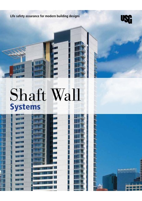
Life safety assurance for modern building designs<br />
Shaft Wall<br />
Systems
Walls that enclose elevator shafts, stairwells and other vertical shafts are the lifeline<br />
of a building. Should a fire occur, firefighters control the use of elevators, leaving<br />
stairwells as the only <strong>me</strong>ans for occupant egress or rescue within the building. Since<br />
these walls are an important part of the building, they must have the strength to<br />
withstand lateral loads and provide needed fire protection.<br />
User’s Guide<br />
-<br />
-<br />
-<br />
This brochure explains:<br />
What a shaft wall system <strong>com</strong>prises<br />
The different applications where shaft wall systems can be used<br />
How to select and specify the appropriate <strong>com</strong>ponents of a shaft<br />
wall system<br />
Pages<br />
Understand Your System<br />
4<br />
Overview<br />
Applications<br />
Sustainability<br />
High-Performance Shaft Walls<br />
Understand Your System<br />
10<br />
Performance Selector<br />
Limiting Heights<br />
Design Your System<br />
13<br />
Design Details<br />
Specify Your System<br />
21<br />
Application Guide Specifications<br />
For More Information<br />
Technical Service<br />
Website:<br />
www.usg-<strong>me</strong>.<strong>com</strong><br />
www.usg.<strong>com</strong><br />
3 USG Shaft Wall Systems
Overview<br />
Applications<br />
SHEETROCK Brand Shaft Wall Systems are non-loadbearing gypsum wall<br />
partition assemblies constructed from outside the shaft at each floor.<br />
Shafts are enclosed early in construction, and the walls are finished later along<br />
with interior partitions. Installation is quick and easy, using <strong>com</strong>ponents and<br />
application procedures familiar to <strong>me</strong>chanics. This system installs faster than<br />
other multilayer gypsum panel systems because it is installed from one side,<br />
leaving the shaft free of scaffolding. The assemblies are constructed of gypsum<br />
liner panels friction-fitted into C-H studs in a progressive manner, with gypsum<br />
panels, gypsum fiber panels or ce<strong>me</strong>nt board applied to the face.<br />
Walls<br />
Use SHEETROCK Brand Shaft Wall Systems to construct elevator shafts,<br />
<strong>me</strong>chanical shafts, stairwells, air return shafts and horizontal <strong>me</strong>mbranes.<br />
These shafts are vital for vertical <strong>com</strong>munication, power, water, fresh air,<br />
exhaust, and a <strong>me</strong>ans of egress.<br />
Intermittent Air Pressure Loads<br />
Typical Shaft<br />
Wall Assembly<br />
Utility Chase<br />
USG C-H Stud<br />
1”SHEETROCK Brand gypsum liner<br />
or enhanced gypsum liner panels<br />
USG J-Runner<br />
Two USG J-Runners<br />
1”SHEETROCK Brand gypsum liner<br />
or enhanced gypsum liner panels<br />
Elevator shafts<br />
Ideal for elevator shafts since the walls can be constructed<br />
from one side, leaving the shaft free of scaffolding. This<br />
allows elevator equip<strong>me</strong>nt to be installed simultaneously.<br />
Intermittent Air Pressure Loads<br />
Stair shafts<br />
Ac<strong>com</strong>modates stair shafts by allowing both sides of<br />
the wall to be finished when required. For added abuse<br />
resistance in stairwells, face layer panels can be<br />
substituted with FIBEROCK Brand Abuse-Resistant Panels.<br />
Sustained Pressure Loads<br />
USG C-H Stud<br />
SHEETROCKBrand gypsum panels<br />
SHEETROCKBrand gypsum panels<br />
Elevator shaft<br />
Elevator shaft door fra<strong>me</strong><br />
Elevator car<br />
Mechanical shafts<br />
Vertical HVAC piping and ductwork can easily be<br />
contained within the system, as well as allowing for wall<br />
penetrations when required.<br />
Air shafts (unlined)<br />
The system can also be used for vertical air shafts<br />
within the building. Shafts can be unlined when specific<br />
conditions are <strong>me</strong>t. Unlined shaft walls can ac<strong>com</strong>modate<br />
sustained air pressure up to 10 psf.<br />
4 USG Shaft Wall Systems<br />
5 USG Shaft Wall Systems
Applications<br />
Walls<br />
Solid Shafts<br />
Horizontal Stud Shafts<br />
Steel Framing<br />
USG Steel J-Runner (JR)<br />
USG Steel C-H Stud (CH)<br />
2"<br />
1 1 /2"<br />
2 1 /2", 4", 6"<br />
1"<br />
2 1 /2", 4", 6"<br />
1 3 /8"<br />
7 /32"<br />
1"<br />
USG Steel Jamb-Strut (JS)<br />
USG Steel E-Stud (ES)<br />
Solid shafts are normally used in areas where a small<br />
section of shaft wall is needed for a single vertical pipe<br />
penetration. The solid shaft is structurally limited to a height<br />
of 12 feet, since the system has no studs.<br />
For certain applications, equip<strong>me</strong>nt limitations so<strong>me</strong>ti<strong>me</strong>s<br />
make it difficult to install shaft liner panels and studs vertically.<br />
This is true for walls separating shafts when there is<br />
only a structural beam provided for supporting the wall.<br />
1"<br />
2 1 /2", 4", 6" 3"<br />
1"<br />
2 1 /2"<br />
1"<br />
4", 6"<br />
3 /8"<br />
Ceilings<br />
Shafts Wall Ceiling Membrane<br />
1"<br />
3 /4"<br />
1"<br />
3 /4"<br />
Thickness-Steel Framing a Components<br />
Style<br />
CH, ES, JR, JS<br />
Design Thickness b<br />
in.<br />
0.0359<br />
Minimum Thickness<br />
mm in.<br />
mm ga.<br />
0.90 0.0341 0.90 20<br />
The system can also be installed horizontally when a<br />
horizontal fire-rated <strong>me</strong>mbrane is required. Membranes have<br />
been approved under NER-258 for 1- and 2-hour fire ratings.<br />
Thickness-Steel Framing a Components<br />
Item Code Description Thickness Thickness Average Weight Area (sq.in.)<br />
Gauge (mm) (lb/lin.ft)<br />
212CH-34 USG Steel C-H Stud (CH) (1½” x 2½” x 1⅜”) 20 0.90 1.007<br />
0.301<br />
400CH-34 USG Steel C-H Stud (CH) (1½” x 4” x 1⅜”) 20 0.90 1.185<br />
0.354<br />
600CH-34 USG Steel C-H Stud (CH) (1½” x 6” x 1⅜”) 20 0.90 1.423<br />
0.425<br />
212ES-34 USG Steel E-Stud (ES) (1” x 2½” x ¾”) 20 0.90 0.765<br />
0.228<br />
400ES-34 USG Steel E-Stud (ES) (1” x 4” x ¾”) 20 0.90 0.941<br />
0.282<br />
600ES-34 USG Steel E-Stud (ES) (1” x 6” x ¾”) 20 0.90 1.1806 0.353<br />
212JR-34<br />
400JR-34<br />
600JR-34<br />
USG Steel J-Runner (JR) (1” x 2½” x 2”) 20<br />
USG Steel J-Runner (JR) (1” x 4” x 2”) 20<br />
USG Steel J-Runner (JR) (1” x 6” x 2”) 20<br />
0.90<br />
0.90<br />
0.90<br />
0.639<br />
0.732<br />
1.0495<br />
0.1911<br />
0.219<br />
0.314<br />
212JS-34<br />
400JS-34<br />
600JS-34<br />
USG Steel Jamb Strut (JS) (1” x 2½” x 3”) 20<br />
USG Steel Jamb Strut (JS) (1” x 4” x 3”) 20<br />
USG Steel Jamb Strut (JS) (1” x 6” x 3”) 20<br />
0.90<br />
0.90<br />
0.90<br />
0.756<br />
0.933<br />
1.171<br />
0.226<br />
0.279<br />
0.35<br />
6 USG Shaft Wall Systems<br />
7 USG Shaft Wall Systems<br />
Note<br />
(a) Studs and runners <strong>com</strong>ply with ASTM C645. (b) Properties of steel framing <strong>me</strong>mbers have been calculated in conformance with ANSI Specification for the Design of<br />
Cold-For<strong>me</strong>d Steel Structural Members, 1996 edition. (c) Full section modulus to be used with corresponding design stress.
Performance Testing<br />
Testing Results<br />
Sustainability<br />
The LEED® (Leadership in Energy and Environ<strong>me</strong>ntal Design) program is a guideline for building solutions<br />
established by the U.S. Green Building Council (USGBC).<br />
LEED's mission is to transform the building industry by establishing a <strong>com</strong>mon standard of <strong>me</strong>asure<strong>me</strong>nt to<br />
define what constitutes a “green building.” To this end, LEED provides a fra<strong>me</strong>work for assessing building<br />
performance and <strong>me</strong>eting sustainability goals. This fra<strong>me</strong>work assigns points for certain sustainability<br />
criteria, such as sustainable site develop<strong>me</strong>nt, water savings, energy efficiency, materials selection and<br />
indoor environ<strong>me</strong>ntal quality.<br />
Specific products cannot be LEED-certified, because there are many contingent factors on each project that<br />
must be considered. However, certain products may assist you in obtaining LEED points for your design<br />
solution. For example:<br />
USGBC LEED Credits<br />
Product Family<br />
95% gypsum, 5% paper,<br />
SHEETROCK Brand Panels- ~5% 0%-95% 3.6 MJ/kg 43-50 none 95+%<br />
23 plants nationwide d ave.<br />
with wax and glass fiber<br />
Percent varies across<br />
36.5%<br />
1% starch; special panel<br />
SHEETROCK Brand Paper Tape 0 0 6 MJ/kg<br />
none 95+% Paper<br />
SHEETROCK Brand<br />
0 25% 40.8 MJ/kg<br />
none<br />
Steel,paper & non-solvent<br />
Paper-Faced Bead<br />
organic adhesive<br />
SHEETROCK Brand Metal Bead 0 25% 34.8MJ/kg<br />
none<br />
Steel<br />
Joint Compound-<br />
0 0 3 MJ/KG 100
Performance Selector<br />
Wall Systems — Limiting Heights<br />
Wall Systems — Limiting Heights Table<br />
Structural<br />
Performance<br />
Limiting Heights<br />
Elevator Shaft<br />
Pressures<br />
A.<br />
B.<br />
C.<br />
SHEETROCK Brand Shaft Wall Systems are engineered to withstand<br />
pressure loads and provide in-service impact resistance to ensure long-term<br />
performance and durability. Use this section to determine the size and<br />
gauge of framing for the system you select. You will need to know elevator<br />
pressures and other in-service demands.<br />
Impact-Resistant for Durability<br />
Impacted with a 60 lb. sand bag, SHEETROCK Brand Shaft Wall Systems proved durable. In the test, three<br />
impacts each were made at 15 ft.-lb., 30 ft.-lb., and each following 15 ft.-lb. interval until failure. At 270<br />
ft.-lb. the test was stopped; while cracked, the wall was not penetrated. For additional information about<br />
abuse-resistant, secure or other hardened applications, contact United States Gypsum Company at 800<br />
USG.4YOU.<br />
Flexing Resistance for In-Service Performance<br />
Shaft walls are subjected to both positive and negative pressures as elevator cabs rise and descend. This<br />
piston effect of an elevator in its shaft causes continual flexing of the shaft wall. In tests, SHEETROCK Brand<br />
Shaft Wall Systems were subjected to over one million full oscillation cycles to model wall performance<br />
through the life of the building. These tests showed that a 25 ga. J-Runner is inadequate at the top or<br />
bottom of a shaft wall. As the long runner leg is continually flexed from wall deflection, it can rupture and<br />
screws can strip out and fracture from the flexing. Oscillation tests showed 24 ga. J-Runners minimize these<br />
problems and are essential to long-term safety.<br />
Maximum partition heights are shown for four different intermittent air pressure loads and three allowable<br />
deflections. The applied pressure load is selected by the designer based on elevator cab speed and the number<br />
of elevators per shaft. Instead of using only deflection criteria, United States Gypsum Company design data<br />
consider several additional factors in determining limiting partition heights.<br />
Bending stress—the unit force exerted which will break or distort the stud.<br />
End reaction shear—determined by the amount of force applied to the stud which will bend or shear the<br />
J-Runner or cripple the stud.<br />
Deflection—the actual deflection under a load. Allowable deflection is based on the amount of bending<br />
under load that a particular wall can experience without exceeding a prescribed ratio<br />
related to partition height.<br />
The air pressure load on shaft walls depends upon the elevator cab speed and the number of elevators per<br />
shaft. The following re<strong>com</strong><strong>me</strong>ndations are derived from United States Gypsum Company tests conducted in<br />
three high-rise buildings ranging in height from 17 to 100 stories.<br />
Intermittent Air Pressure<br />
Load (wind load)–psfa<br />
Stud Type<br />
and Size<br />
Designation<br />
Allowable<br />
deflection<br />
Fire-rated system B,D,F,G,H,I<br />
2-1/2’’ C-H Studs<br />
4” C-H Studs<br />
6” C-H Studs<br />
Double 6” C-H Studs d<br />
Stud Type<br />
and Size<br />
2-1/2’’ C-H Studs<br />
4” C-H Studs<br />
6” C-H Studs<br />
Double 6” E-Studs d 212CH-34<br />
400CH-34<br />
600CH-34<br />
600ES-34<br />
Designation<br />
212CH-34<br />
400CH-34<br />
600CH-34<br />
600ES-34<br />
L/120<br />
L/240<br />
L/360<br />
L/120<br />
L/240<br />
L/360<br />
L/120<br />
L/240<br />
L/360<br />
L/120<br />
L/240<br />
L/360<br />
Allowable<br />
deflection<br />
L/120<br />
L/240<br />
L/360<br />
L/120<br />
L/240<br />
L/360<br />
L/120<br />
L/240<br />
L/360<br />
L/120<br />
19’2’’(d)<br />
15’3’’(d)<br />
13’4’’(d)<br />
22’10’’(d)<br />
18’2’’(d)<br />
15’10’’(d)<br />
28’0’’(c)<br />
25’1’’(d)<br />
21’11’’(d)<br />
28’0”(c)<br />
28’0”(c)<br />
26’3”(d)<br />
Fire-rated<br />
5<br />
—<br />
—<br />
—<br />
22’0’’(d)<br />
17’6’’(d)<br />
15’3”(d)<br />
28’0’’(c)<br />
24’3’’(d)<br />
21’22’’(d)<br />
28’0”(c)<br />
15’9”(f)<br />
13’4”(d)<br />
11’7”(d)<br />
20’0”(d)<br />
15’10”(d)<br />
13’10”(d)<br />
27’7”(d)<br />
21’11”(d)<br />
19’2”(d)<br />
28’0”(c) e<br />
26’3”(d) e<br />
23’0”(d)<br />
system<br />
7٫5<br />
—<br />
—<br />
—<br />
19’3’’(d)<br />
15’3’’(d)<br />
13’4’’(d)<br />
26’8’’(d) e<br />
21’2’’(d) e<br />
18’6’’(d)<br />
28’0”(c) e<br />
13’8”(f)<br />
12’1”(d)<br />
10’7”(d)<br />
18’2”(d)<br />
14’5”(d)<br />
12’7”(d)<br />
24’8”(f) e<br />
19’11’’(d)<br />
17’5”(d)<br />
28’0”(c) e<br />
24’0”(d) e<br />
21’0”(d) e<br />
C c<br />
10<br />
—<br />
—<br />
—<br />
17’6’’(d) e<br />
13’11’’(d)<br />
12’2’’(d)<br />
20’2’’(v) e<br />
19’3’’(d) e<br />
16’9’’(d) e<br />
28’0”(c) e<br />
L/240 28’0”(c) 24’9”(d) 22’6”(d) e<br />
L/360 25’3”(d) 21’9”(d) 19’6’’(d)<br />
5<br />
7٫5<br />
10<br />
15<br />
11’2’’(f)<br />
10’7’’(d)<br />
9’3’’(d)<br />
15’0’’(f) e<br />
12’7’’(d)<br />
11’0”(d)<br />
18’0’’(v) e<br />
17’5’’(d) e<br />
15’2’’(d)<br />
20’0”(v) e<br />
20’0”(v) e<br />
18’3”(d) e<br />
15<br />
—<br />
—<br />
—<br />
15’0’’(f) e<br />
12’2’’(d) e<br />
10’7”(d) e<br />
13’6’’(v) e<br />
13’6’’(v) e<br />
13’6’’(v) e<br />
20’0”(v) e<br />
20’0”(v) e<br />
17’3”(d) e<br />
Fire-rated System E b<br />
5 7٫5 10<br />
17’7’’(d)<br />
14’0’’(d)<br />
12’2’’(d)<br />
23’7’’(d)<br />
15’4”(d)<br />
12’2”(d)<br />
10’8”(d)<br />
20’7”(d)<br />
13’8”(f)<br />
11’1”(d)<br />
9’8”(d)<br />
18’5”(f)<br />
18’9’’(d) 16’4”(d) 14’10”(d)<br />
16’4’’(d) 14’3”(d) 13’0”(d)<br />
28’0’’(c) 26’5”(d) e 24’0”(f) e<br />
24’0’’(d) 20’11”(d) e 19’0’’(d)<br />
20’11’’(d) 18’4”(d) 16’8”(d)<br />
28’0”(c) 28’0”(c) e 28’0”(c) e<br />
28’0”(c) 26’0”(d) e 23’6”(d) e<br />
26’3”(d) 22’9”(d) 20’6”(d) e<br />
Fire-rated System a c<br />
5 7٫5 10<br />
17’2’’(d)<br />
14’0’’(d)<br />
12’3’’(d)<br />
14’8”(f)<br />
12’3”(d)<br />
10’8”(d)<br />
12’9”(f)<br />
11’1”(d)<br />
9’0”(d)<br />
22’0’’(d) 19’3’’(d) 17’6’’(d) e<br />
17’6’’(d) 15’3’’(d) 13’11’’(d)<br />
15’3’’(d) 13’4’’(d) 12’2’’(d)<br />
28’0’’(c) 28’0’’(c) 20’2’’(v) e<br />
24’3’’(d) 21’2’’(d) e 19’3’’(d) e<br />
20’2’’(d) 18’6’’(d) 16’9’’(d) e<br />
28’0”(c) 28’0”(c) e 28’0”(c) e<br />
28’0”(c) 24’9”(d) 22’6’’(d) e<br />
25’3”(d) 21’9”(d) 19’6”(d)<br />
15<br />
11’2’’(f)<br />
9’8’’(d)<br />
8’6’’(d)<br />
15’0’’(f) e<br />
13’0’’(d)<br />
11’4”(d)<br />
18’0’’(v) e<br />
16’8’’(d) e<br />
14’6’’(d)<br />
20’0”(v) e<br />
20’0”(v) e<br />
18’0”(d) e<br />
15<br />
10’5’’(f)<br />
9’8’’(d)<br />
8’6’’(d)<br />
15’0’’(f) e<br />
12’2’’(d) e<br />
10’7”(d) e<br />
13’6’’(v)<br />
13’6’’(v) e<br />
13’6’’(v) e<br />
20’0”(v) e<br />
20’0”(v) e<br />
17’3”(d) e<br />
Re<strong>com</strong><strong>me</strong>nded Elevator Shaft Pressure Load<br />
Elevator Velocity ft./min. One or two elevators per shaft Three or more elevators per shaft<br />
0 to 180 5.0 psf 5.0 psf<br />
180 to 700 7.5 psf 5.0 psf<br />
700 to 1,600 10.0 psf 7.5 psf<br />
1,600 to 2,000 15.0 psf 7.5 psf<br />
Note<br />
Runner fasteners should withstand 193 lb. single shear and 200 lb. bearing force; attach<strong>me</strong>nt spacing should not exceed 24’’ o.c. See the Performance Selector for<br />
system references and rated assembly details. L/180 data available upon request from United States Gypsum Company. Limiting criteria: f–bending stress,<br />
d–deflection, v–end reaction shear, c–practical limitation. (a) Stud spacing of 24’’ for all values. (b) For assembly with single-layer board both sides of studs.<br />
(c) For assembly with single-layer board attached to studs. (d) Attach<strong>me</strong>nt of USG Steel Double 6’’ E-Stud for SHEETROCK Brand Shaft Wall Systems. The studs are<br />
to be attached back-to-back (web to web) with pairs 1/2’’ of type S-12 pan head screws installed in two rows, spaced as widely apart as possible. The first and last<br />
pairs of fasteners shall start within 6’’ of each end of the studs. They shall then be spaced at a maximum of 12’’ on center throughout the body of the entire stud.<br />
(e) Use JR20 runner for this height.<br />
Note<br />
(a) Single-cab high-speed elevator shafts may require special design considerations.<br />
10 USG Shaft Wall Systems<br />
11 USG Shaft Wall Systems
Performance Selector<br />
Design Details<br />
Wall Systems — Limiting Heights<br />
Ceiling Membrane<br />
Unlined Shafts<br />
1.<br />
2.<br />
3.<br />
4.<br />
5.<br />
Gypsum shaft walls have been used for many years for vent and air shafts. Their fire-resistant features and<br />
economical dry construction make them ideal for this use. To function properly, vent and air shaft systems<br />
should be designed with the following performance provisions:<br />
Gypsum board surface temperature does not exceed 125 °F.<br />
Separate approved liners should be installed in areas subject to continuous moisture overspray, condensation<br />
or air stream temperature over 125 °F.<br />
Air stream dew point temperatures are maintained below gypsum board surface temperature.<br />
The assembly is constructed to withstand sustained design uniform air pressure loads not exceeding 10<br />
psf. Startup surge loads should not be greater than 1-1/2 ti<strong>me</strong>s the design static load. (See table below for<br />
limiting heights.)<br />
To ensure airtight construction, select appropriate sealants and apply where required.<br />
2-Hr. Rated Assembly – Horizontal Membrane or Metal Duct Enclosure<br />
duct surface<br />
fastener 24" o.c. max. (shear and<br />
withdrawal resistance as required by<br />
specific design conditions<br />
sealant<br />
1 /2‘’ type S pan<br />
head screw at<br />
12" o.c. (attach<br />
both sides of C-H<br />
stud & J-runner<br />
at top and bottom<br />
of stud<br />
Sustained pressure load–psf<br />
2-hr. fire-rated system<br />
1-hr. fire-rated system<br />
fastener 24" o.c. max. (shear and<br />
withdrawal resistance as required<br />
by specific design conditions<br />
1" SHEETROCK Brand<br />
gypsum liner panel<br />
max. height 4'-0"<br />
Stud Type<br />
and Size<br />
Designation<br />
Stud<br />
Spacing<br />
2-1/2’’ C-H Studs<br />
4” C-H Studs<br />
6” C-H Studs<br />
Double 6” E-Studs d 212CH-34<br />
400CH-34<br />
600CH-34<br />
600ES-34<br />
24’’<br />
24’’<br />
24’’<br />
24’’<br />
L/120<br />
L/240<br />
L/360<br />
L/120<br />
L/240<br />
L/360<br />
L/120<br />
L/240<br />
L/360<br />
L/120<br />
L/240<br />
L/360<br />
Allowable<br />
deflection<br />
5 10 5<br />
10<br />
14’8’’<br />
13’4’’<br />
11’7’’<br />
20’0’’<br />
15’10’’<br />
13’10’’<br />
27’7’’<br />
21’11’’<br />
19’2’’<br />
28’0’’<br />
26’3’’<br />
23’0’’<br />
10’5’’<br />
10’7’’<br />
9’3’’<br />
15’0’’ a<br />
12’7’’<br />
11’0’’<br />
14’8’’<br />
12’2’’<br />
10’8’’<br />
19’3’’<br />
15’3’’<br />
13’4’’<br />
18’0’’ a<br />
26’8’’ a<br />
17’5’’ a<br />
21’2’’<br />
15’2’’<br />
18’6’’<br />
20’0’’ a<br />
28’0’’ a<br />
20’0’’ a<br />
24’9’’<br />
18’3’’ a 21’9’’<br />
10’5’’<br />
9’8’’<br />
8’3’’<br />
15’0’’ a<br />
12’2’’ a<br />
10’7’’ a<br />
13’6’’ a<br />
13’6’’ a<br />
13’6’’ a<br />
20’0’’ a<br />
20’0’’ a<br />
17’3’’ a<br />
sealant<br />
USG steel C-H stud<br />
Rotated Section<br />
max. span 8'-11" with 25 ga. studs<br />
max. span 11'-8" with 20 ga. studs<br />
USG steel J-runner<br />
1-Hr. Fire Rated Assembly (see NER-258) – Corridor Ceiling and Stair Soffit<br />
SHEETROCK Brand<br />
gypsum panels<br />
2-Hr. Fire Rated Assembly (see NER-258) – Corridor Ceiling and Stair Soffit<br />
1" SHEETROCK Brand<br />
gypsum liner panel<br />
1" SHEETROCK Brand<br />
gypsum liner panel<br />
USG steel<br />
C-H stud<br />
fasteners as<br />
required 24" o.c.<br />
USG steel J-runner<br />
USG steel<br />
C-H stud<br />
fasteners as<br />
required 24" o.c.<br />
USG steel J-runner<br />
SHEETROCK Brand<br />
gypsum panel<br />
sealant<br />
SHEETROCK Brand<br />
gypsum panels<br />
sealant<br />
Note<br />
Runner fasteners should withstand 193 lb. single shear and 200 lb. bearing force; attach<strong>me</strong>nt spacing should not exceed 24’’ o.c. (a) Use JR20 runner for this height.<br />
12 USG Shaft Wall Systems<br />
13 USG Shaft Wall Systems
Design Details<br />
Basic Interfaces — System B<br />
Head Section<br />
Dynamic Head Section (UL Design HW-D-0372)<br />
Wall Junction<br />
Outside Corner<br />
1" max.<br />
3 /8" to 1 /2"<br />
USG steel J-runner<br />
sealant as required<br />
for sound<br />
1 1 /2" min.<br />
USG steel C-H stud<br />
SHEETROCK Brand<br />
gypsum panels<br />
1" SHEETROCK Brand<br />
gypsum liner panel<br />
1 /8" max. gap<br />
3" max.<br />
1" max.<br />
3 /8" to 1 /2"<br />
SHEETROCK Brand<br />
gypsum liner<br />
panel 6" wide<br />
strip to flute contour<br />
1" SHEETROCK Brand<br />
gypsum liner panel<br />
5 /8" joint width<br />
with sealant<br />
mineral wool<br />
batt 4 pcf min.<br />
USG steel J-runner<br />
1 1 /2" min.<br />
1" mineral wool<br />
batt 4 pcf min.<br />
USG steel C-H stud<br />
SHEETROCK Brand<br />
gypsum panels<br />
USG steel<br />
C-H stud<br />
sealant<br />
1" SHEETROCK Brand<br />
gypsum liner panel<br />
USG steel J-runner<br />
1" SHEETROCK Brand<br />
gypsum liner panel<br />
USG corner<br />
reinforce<strong>me</strong>nt<br />
SHEETROCK Brand<br />
gypsum panels<br />
USG steel J-runner<br />
1" SHEETROCK Brand<br />
gypsum liner panel<br />
Base Section<br />
Call Button Box<br />
Wall Intersection<br />
Inside Corner<br />
25 ga. steel strip<br />
(6"x12" min.)<br />
4" min<br />
over<br />
2"<br />
75˚<br />
min.<br />
1" SHEETROCK Brand<br />
gypsum liner panel<br />
SHEETROCK Brand<br />
gypsum panels<br />
gypsum panel cant screw–<br />
attached to vertical studs<br />
(for projections over 2")<br />
USG steel C-H stud<br />
USG steel J-runner<br />
sealant as required<br />
for sound<br />
call button box<br />
SHEETROCK Brand<br />
gypsum panels<br />
1" SHEETROCK Brand<br />
gypsum liner panels<br />
sealant<br />
USG steel J-runner<br />
fasteners as<br />
required 24" o.c.<br />
SHEETROCK Brand<br />
gypsum panels<br />
1" SHEETROCK Brand<br />
gypsum liner panel<br />
SHEETROCK Brand<br />
gypsum panels<br />
USG corner<br />
reinforce<strong>me</strong>nt<br />
USG steel C-H stud<br />
USG steel J-runner<br />
1" SHEETROCK Brand<br />
gypsum liner panel<br />
14 USG Shaft Wall Systems<br />
15 USG Shaft Wall Systems
Design Details<br />
Basic Interfaces — System B<br />
Outlet/Switch Box<br />
Control Joint<br />
Handrail Application<br />
Steel Beam<br />
1" SHEETROCK Brand<br />
gypsum liner panels<br />
1" SHEETROCK Brand<br />
gypsum liner panels<br />
1 /2" joint width<br />
outlet box<br />
Note: the surface area of individual<br />
outlet or switch boxes shall not<br />
exceed 16 square inches. The<br />
aggregate surface area of all boxes<br />
shall no exceed 100 square inches.<br />
(per U.L. fire resistance directory)<br />
SHEETROCK Brand<br />
gypsum panels<br />
USG steel J-runner<br />
SHEETROCK Brand<br />
gypsum panels<br />
sealant<br />
mineral wool insulation<br />
control joint<br />
steel plate (20 ga. min.)<br />
fastened to studs parallel<br />
to stringers as required<br />
1" SHEETROCK Brand<br />
gypsum liner panel<br />
SHEETROCK Brand<br />
gypsum panel<br />
steel beam with fireproofing<br />
power-actuated<br />
fastener 24" o.c.<br />
USG steel J-runner<br />
attached to beam<br />
before fireproofing<br />
1" SHEETROCK Brand<br />
gypsum liner panel<br />
SHEETROCK Brand<br />
gypsum panels<br />
Stair Hanger and Rod Application<br />
Stair Hanger and Rod Application Cross Section at Stair Hanger<br />
Steel Beam with Z-Clip<br />
Steel Beam with Offset<br />
stairwell side<br />
stair stringer<br />
hanger rod<br />
1" SHEETROCK Brand<br />
gypsum liner panel<br />
SHEETROCK Brand<br />
gypsum panel<br />
stair landing<br />
hanger rod<br />
steel beam with fireproofing<br />
steel beam with fireproofing<br />
SHEETROCK Brand<br />
gypsum panels<br />
USG steel C-H<br />
stud 24" o.c.<br />
Z-clip attached to beam<br />
before fireproofing<br />
Z-clip max. spacing<br />
24" o.c. min. 20 ga. min.<br />
2 fasteners per leg<br />
1 1 /2" min.<br />
8" max.<br />
fasteners<br />
steel angle<br />
1" SHEETROCK Brand<br />
gypsum liner panel<br />
fasteners<br />
USG steel J-runner<br />
1" SHEETROCK Brand<br />
gypsum liner panel<br />
USG steel C-H stud<br />
SHEETROCK Brand<br />
gypsum panels<br />
SHEETROCK Brand<br />
gypsum panels<br />
continuous 14 ga.<br />
steel plate<br />
USG steel J-runner<br />
attached to beam<br />
before fireproofing<br />
1" SHEETROCK Brand<br />
gypsum liner panel<br />
16 USG Shaft Wall Systems<br />
17 USG Shaft Wall Systems
Design Details<br />
Fire Damper<br />
Elevator Door Framing<br />
Typical Penetrations Elevation at Duct Opening<br />
Elevator Door Framing<br />
Elevator Door Rough Opening<br />
USG steel J-runner<br />
A<br />
duct opening<br />
B<br />
USG steel J-runner<br />
ceiling<br />
20 ga. jamb strut<br />
screw attached<br />
both sides<br />
USG C-H stud<br />
A<br />
A<br />
USG C-H stud<br />
10'-0"<br />
max<br />
USG steel E-studs<br />
back to back<br />
USG steel C-H studs<br />
USG steel J-runner<br />
USG steel<br />
J-runner<br />
screw attached<br />
both sides<br />
USG steel<br />
J-runner<br />
USG steel J-runner<br />
USG steel<br />
J-runner header<br />
USG jamb strut<br />
5'-0" max. opening<br />
20 ga. jamb strut<br />
10'-0"<br />
max<br />
1" SHEETROCK<br />
Brand gypsum<br />
liner panel on each<br />
side of jamb strut<br />
USG steel J-runner<br />
Section A<br />
1-1/2 Hr. Fire Damper Tested per UL R13479<br />
Section B<br />
1-1/2 Hr. Fire Damper Tested per UL R13479<br />
screw attached<br />
both sides<br />
USG steel J-runner<br />
Section A-A Detail<br />
1" SHEETROCK<br />
Brand gypsum<br />
liner panel<br />
USG steel<br />
J-runner<br />
header<br />
1 /2" max.<br />
damper sleeve<br />
SHEETROCK Brand<br />
gypsum panels<br />
1 /2" x 1 /2" x<br />
16 gauge<br />
galvanized angle<br />
damper sleeve<br />
1 /2" max.<br />
USG steel E-stud<br />
SHEETROCKBrand<br />
gypsum panels<br />
fasten both<br />
sides of C-H<br />
stud to J runner<br />
1" SHEETROCK<br />
Brand gypsum<br />
liner panel<br />
screw attach<br />
at bottom leg<br />
of C-H stud<br />
1 /2" x 1 /2" x<br />
16 gauge<br />
galvanized angle<br />
18 USG Shaft Wall Systems<br />
19 USG Shaft Wall Systems<br />
Note<br />
1. Framing at elevator door shall be a minimum 4’’ studs and runners 20 gauge.<br />
2. Horizontal place<strong>me</strong>nt of liner panel and C-H Studs per UL Design U437.<br />
3. Flanges of the jamb strut must be continously braced by screw connections to the liner and face panels 12’’ o.c.<br />
4. For doors greater than 5’ wide and/or transom heights greater than 4’, reinforce the 400JS-34 with a nested 400ES-34.
Design Details<br />
Application Guide<br />
Specifications<br />
Wall Systems – Horizontal C-H Studs<br />
Horizontal Shaftwall Elevation<br />
USG steel<br />
J-runner header<br />
USG C-H studs<br />
USG steel J-runners<br />
Section B-B Wall Intersection<br />
C<br />
C<br />
1" SHEETROCK Brand<br />
gypsum liner panels<br />
A<br />
A<br />
D<br />
D<br />
B<br />
B<br />
Section C-C Head Section<br />
sealant<br />
5 /8" SHEETROCK<br />
Brand FIRECODE Core<br />
gypsum panels<br />
Section D-D Base Section<br />
1"<br />
structural <strong>me</strong>mber<br />
USG steel J-runner<br />
1" SHEETROCK Brand<br />
gypsum liner panel<br />
Shaft Wall<br />
Installation<br />
A.<br />
1.<br />
2.<br />
3.<br />
4.<br />
5.<br />
6.<br />
7.<br />
USG Steel Framing and SHEETROCK Brand Gypsum Liner Panels<br />
Position steel J-runners at floor and ceiling with the short leg toward finish side of wall.<br />
Securely attach runners to structural supports with powder actuated fasteners at both ends and max. 24’’ o.c.<br />
For attach<strong>me</strong>nt to steel fra<strong>me</strong> construction install floor and ceiling J-Runners and J-Runners or E-Studs on<br />
columns and beams before steel is fireproofed.<br />
For attach<strong>me</strong>nt to structural steel use Z-shaped stand-off clips secured to structural steel before fireproofing<br />
application.<br />
Remove spray-fireproofing from J-Runners and E-Studs before installing gypsum liner panels.<br />
For wall heights less than maximum available panel height cut gypsum liner panels no more than 1’’ less than<br />
floor-toceilingheight and erect vertically between J-Runners.<br />
Where shaft wall height shaft exceed maximum available panel length pieces of gypsum liner panel must be<br />
butted together at factory cut ends.<br />
a. Position gypsum liner panel end joints within upper and lower third points of wall.<br />
b. Stagger joints top and bottom in adjacent panels.<br />
c. Screw studs to runners on walls over 16.<br />
Cut C-H Studs 3/8’’ to not more than 1/2’’ less than floor-to-ceiling height.<br />
Install C-H Studs between gypsum liner panels with liner securely engaged.<br />
8.<br />
9.<br />
10. Terminations: Install full-length steel E-Studs or J-Runners vertically at T-intersections, corners, door jambs, and<br />
columns.<br />
11. Openings: Fra<strong>me</strong> with vertical E-Stud or J-Runner at vertical edges, horizontal J-Runner at head and sill.<br />
Reinforce as shown in this brochure. Suitably fra<strong>me</strong> all openings to maintain structural support for wall.<br />
12. Elevator Door Fra<strong>me</strong>s: Install jamb struts each side of elevator door fra<strong>me</strong>s to act as strut-studs.<br />
13. Steel Hinged Door Fra<strong>me</strong>s: Install floor-to-ceiling steel E-Studs each side to act as strut-studs.<br />
14. Attach strut-stud (see 3.2.A.12 or 3.2.A.13) to floor and ceiling runners with two 3/8’’ TYPE S-12 pan head<br />
screws. Attach strut-studs to jamb anchors with 1/2’’ TYPE S-12 screws. Over steel doors, install a cut-tolength<br />
section of J-Runner and attach to strut-studs with 3/8’’ TYPE S-12 screws.<br />
5 /8" SHEETROCK<br />
Brand FIRECODE Core<br />
gypsum panels<br />
1" SHEETROCK Brand<br />
gypsum liner panel<br />
locate screws<br />
to avoid studs<br />
sealant<br />
USG steel C-H stud<br />
USG steel J-runner<br />
3 /8" J-runner to stud<br />
1 /2" J-runner to panel<br />
5 /8 " SHEETROCK<br />
Brand FIRECODECore<br />
gypsum panels<br />
sealant<br />
1" SHEETROCK Brand<br />
gypsum liner panel<br />
USG steel J-runner<br />
structural <strong>me</strong>mber<br />
B.<br />
C.<br />
1.<br />
2.<br />
3.<br />
4.<br />
5.<br />
6.<br />
Resilient Channels<br />
Install Resilient Channels (RC-1 or equivalent) horizontally to face of studs, within 6’’ of floor and ceiling.<br />
Apply Resilient Channels a maximum of 24’’ o.c. vertically (with open face up).<br />
Attach Resilient Channels to studs with 3/8’’ TYPE S screws driven through holes in mounting flange.<br />
Splice channel by nesting directly over stud; screw-attach through both flanges. Reinforce with screws at both<br />
ends of splice.<br />
Install 1/2’’ x 3’’ wide continuous gypsum filler strips to top and bottom runner.<br />
Gypsum Panel application with Resilient Channel: Apply base layer horizontally to resilient channels with end<br />
joints staggered. Fasten with 1’’ TYPE S screws 12’’ o.c. Apply face layer vertically with joints staggered; attach<br />
to channels with 1- 5/8 TYPE S screws 12’’ o.c.<br />
SHEETROCK Brand Gypsum Panels<br />
Gypsum panels and fastening must be per the corresponding fire-resistance design number that is the basis of<br />
design. See the Performance Selector in this brochure for specific fire-resistance design numbers. The System<br />
references below correspond to the Performance Selector found on pages 14-15.<br />
Per UL Design U415 SHEETROCK Brand Gypsum Panels may be applied vertically or horizontally in all of<br />
the systems below except System F. Please note appropriate fastener spacing.<br />
System A—U415 or U469, 1 hour fire-resistance rating. Apply one layer 5/8’’ SHEETROCK Brand FIRECODE<br />
Core Gypsum Panels to studs and runners with 1’’ TYPE S or S-12 (typical) Screws. Fastener Spacing – Space<br />
screws 12’’ o.c. for vertical panel application, 8’’ o.c. for horizontal panel application.<br />
Note<br />
Horizontal framing shall be a minimum 4’’ C-H Studs and runners 20 gauge.<br />
20 USG Shaft Wall Systems<br />
21 USG Shaft Wall Systems
Application Guide<br />
Specifications<br />
System B—U415 or U438, 2 hour fire-resistance rating. Apply two layers of 1/2’’ SHEETROCK Brand FIRE-<br />
CODE C Core Gypsum Panels. Apply base layer to studs with 1’’ TYPE S or S-12 (typical) screws. Space screws<br />
24 o.c. along edges and in the field of the panels for vertical application, 16’’ o.c. for horizontal application.<br />
Apply face layer to studs and J-Runners with 1-5/8’’ TYPE S or S-12 (typical) screws. Space screws 12’’<br />
along the edges and in the field when applied vertically, 8’’ o.c. when applied horizontally. Stagger all joints<br />
between base and face layers.<br />
System D—U415 or U459, 2 hour fire-resistance rating. Install 1-1/2’’ THERMAFIBER SAFB mineral wool batts<br />
in stud cavity. Apply base layer of 5/8’’ SHEETROCK Brand FIRECODE C Core Gypsum Panels using 1’’ TYPE<br />
S or S-12 (typical) screws spaced 24 o.c. when applied vertically. Space screws 16’’ o.c. when board applied<br />
horizontally. Apply face layer of 1/2’’ DUROCK Brand Ce<strong>me</strong>nt Board to C-H Studs with 1-5/8’’ DUROCK Brand<br />
Screws spaced 8o.c.<br />
System E—U415 or U467, 2 hour fire-resistance rating. Apply one layer 1/2’’ SHEETROCK Brand FIRECODE C<br />
Core Gypsum Panels to both sides of C-H Studs. Fasten with 1 TYPE S or S-12 (typical) screws. Space screws<br />
12 o.c. along the edges and in the field for vertical panel application, 8 o.c. for horizontal.<br />
System F—U415, 2 hour fire-resistance rating. Apply base layer 1/2 SHEETROCK Brand FIRECODE C Core<br />
Gypsum Panels to resilient channels with 1’’ TYPE S or S-12 (typical) screws spaced 24o.c. Stagger end joints.<br />
Apply face layer 1/2’’ SHEETROCK Brand FIRECODE C Core Gypsum Panels with 1-5/8 TYPE S or S-12 (typical)<br />
screws spaced 12’’ o.c.<br />
D.<br />
7. Steel Angles should be minimum 20 gauge, 2’’ x 2’’ x 2’’ for 4’’ C-H Studs, and 2’’ x 2’’ x 4’’ for 6’’ C-H<br />
Studs. Clips are centered under and tight to the web of the C-H Studs, but not attached to the studs. Clips<br />
are attached through the web of the vertical J-Runners to the underlying structural supporting ele<strong>me</strong>nt with<br />
a minimum of two 1/2’’ Type S-12 pan head screws.<br />
8. As an alternative to the preceding Angle Clip, fasten each end of the horizontal C-H Stud to the vertical<br />
J-Runner legs with 1/2’’ Type S-12 pan-head steel screws on both sides of the wall.<br />
9. End reactions of the horizontal C-H Studs must be ac<strong>com</strong>modated by the structural ele<strong>me</strong>nt required at the<br />
ends of the wall, and must be determined by a licensed professional engineer.<br />
10. The allowable height of the wall is predicated on the structural adequacy of the vertical structural ele<strong>me</strong>nts.<br />
SHEETROCK Brand Gypsum Panels (for vertical and horizontal shaft walls)<br />
Vent Shaft Enclosure—U529, 2-hour fire-resistance rating. Install 1’’ x 2’’’ x 25 ga. galvanized steel angles<br />
as runners on floor, ceilings, and partition ends. Fasten runners or angles securely to structure with suitable<br />
fasteners spaced 24’’ o.c. max. Install 1/2’’ SHEETROCK Brand FIRECODE C Core Gypsum Panels vertically.<br />
Fasten to angles with 1’’ TYPE S or S-12 (typical) screws spaced 12’’ o.c. Apply SHEETROCK Brand DURA-<br />
BOND Setting-Type or EASY SAND Lightweight Setting- Type Joint Compound on back side of liner panel<br />
and sheet-laminate to shaft-side board with vertical joints offset 12’’ from inner board joints. Also screw to<br />
shaft side board with 1-1/2’’ long Type G screws spaced 24’’ o.c. in both directions.<br />
Laminate face board to liner panels in similar manner. Install face boards vertically with joints offset 12’’ from<br />
liner panel joints. Apply pressure when placing boards to ensure good adhesive bond and fasten to liner<br />
panel with 1-1/2’’ Type G screws, spaced 24’’ o.c.<br />
System G—U415, 3 hour fire-resistance rating. Apply two layers of 5/8’’ SHEETROCK Brand FIRECODE C<br />
Core Gypsum Panels using TYPE S or S-12 (typical) screws spaced 12’’ o.c. Apply first and second (inner) layers<br />
vertically or horizontally over room side of steel C-H Studs. When applied vertically, center joints between<br />
panels over studs. Stagger all joints a minimum 24’’. When panels are applied horizontally stagger joints a<br />
minimum 12. Apply third layer of 5/8 SHEETROCK Brand FIRECODE C Core Gypsum Panels vertically or horizontally<br />
over room side of steel C-H Studs using 2-1/4’’ TYPE S or S-12 (typical) screws. Space screws 16 o.c<br />
when board is applied vertically, 12’’ o.c. when board is applied horizontally.<br />
Accessory<br />
Application<br />
A.<br />
B.<br />
Gypsum Panel Joints—Finish all face layer joints and internal angles with a SHEETROCK Brand Interior<br />
Finishing System installed according to manufacturer’s directions. See product folder J1424 for detailed<br />
re<strong>com</strong><strong>me</strong>ndations.<br />
Corner Bead—Reinforce all vertical and horizontal exterior corners with SHEETROCK Brand Paper Faced<br />
Bead. See product folder J1424 for detailed re<strong>com</strong><strong>me</strong>ndations.<br />
System H—U415, 3 hour fire-resistance rating. Alternate to System G above. Apply third layer of 5/8’’ SHEET-<br />
ROCK Brand FIRECODE C Core Gypsum Panels to other side of steel C-H Studs.<br />
C.<br />
Metal Trim—Where shaft wall terminates against masonry or other dissimilar material, apply SHEETROCK<br />
Brand Paper Faced Bead and Trim over face layer edge.<br />
Horizontal Assemblies —2 hour fire-resistance rating. Install three layers of 1/2’’ SHEETROCK Brand<br />
FIRECODE C Core Gypsum Panels to horizontally installed C-H and/or E-Studs. Apply the base layer with 1’’<br />
TYPE S or S-12 (typical) screws spaced 24 o.c. Apply the mid layer in the sa<strong>me</strong> manner with joints offset 2’<br />
and attached with 1-5/8’’ TYPE S or S-12 (typical) screws spaced 12’’ o.c. Apply the face layer attached with<br />
2-1/4’’ TYPE S or S-12 (typical) screws spaced 12’’ o.c. Place face layer end joints between studs and secure<br />
with 1-1/2’’ Type G screws 8’’ o.c.<br />
1.<br />
2.<br />
3.<br />
4.<br />
5.<br />
6.<br />
Horizontal Stud Shaft Wall<br />
Attach horizontal J-Runners at the floor and top of wall and vertical J-Runners to structural supporting<br />
ele<strong>me</strong>nts with powder actuated fasteners located not greater than 2’’ from ends and spaced no more than<br />
24’’ on center with short leg of J-Runner toward the finish side of the wall.<br />
Install Gypsum Liner Panels horizontally without butt joints, which limits the width of the wall to the available<br />
length of the Liner Panels.<br />
Cut Gypsum Liner Panels 1’’ less than the width of the wall, and center the panels between the vertical<br />
J-Runners. The top edge of the uppermost Liner Panel to be cut 1’’ less than the wall height to clear the 1’’<br />
leg of the top J-Runner.<br />
Free edge of the uppermost and lower Liner Panels attached to the long leg of the top and bottom J-Runners<br />
with 1-5/8’’ long Type S or S-12 steel screws spaced no greater than 12 ‘‘on centers.<br />
Cut C-H Studs to maintain a 1/4’’ gap at each end of the wall.<br />
Install C-H Studs horizontally with the open “C” section of the studs facing down, and spaced 24’’ on center.<br />
22 USG Shaft Wall Systems<br />
23 USG Shaft Wall Systems
www.usg-<strong>me</strong>.<strong>com</strong><br />
USG Middle East Ltd.<br />
Dammam, Saudi Arabia<br />
Tel: +966 3 812 0995<br />
Fax: +966 3 812 1029<br />
e-mail: info@usg<strong>me</strong>.<strong>com</strong><br />
Jeddah, Saudi Arabia<br />
Tel: +966 2 639 2172<br />
+966 2 691 0251<br />
Fax: +966 2 682 3711<br />
e-mail: jeddahsales@usg<strong>me</strong>.<strong>com</strong><br />
Riyadh, Saudi Arabia<br />
Tel: +966 1 291 8351<br />
+966 1 291 8923<br />
Fax: +966 1 291 8894<br />
e-mail: riyadhsales@usg<strong>me</strong>.<strong>com</strong><br />
Dubai, U.A.E.<br />
Tel: +971 4 295 4443<br />
Fax: +971 4 295 4566<br />
e-mail: jumandxb@emirates.net.ae<br />
Doha, Qatar<br />
Tel: +974 44 231 146<br />
Fax: +974 44 231 100<br />
qatarsales@usg<strong>me</strong>.<strong>com</strong><br />
Manama, Bahrain<br />
Tel: +973 17 581 596<br />
Fax: +973 17 581 597<br />
info@usg<strong>me</strong>.<strong>com</strong><br />
Beirut, Lebanon<br />
Tel: +961 1 360 888<br />
+961 1 365 309<br />
Fax: +961 1 365 280<br />
+961 1 361 461<br />
e-mail: salesbeirut@usg<strong>me</strong>.<strong>com</strong><br />
Metric Specifications<br />
USG Corporation, through its<br />
operating subsidiaries, will<br />
provide <strong>me</strong>tric conversions on<br />
its products and systems to<br />
help specifiers match <strong>me</strong>tric<br />
design sizes. In addition,<br />
so<strong>me</strong> products are available in<br />
<strong>me</strong>tric di<strong>me</strong>nsions from<br />
selected manufacturing<br />
plants. Refer to SA100,<br />
Fire-Resistant Assemblies, for<br />
additional information and a<br />
Table of Metric Equivalents.<br />
Trademarks<br />
The following trademarks<br />
used herein are owned by<br />
United States Gypsum or a<br />
related <strong>com</strong>pany:<br />
AQUA-TOUGH,<br />
DUR-A-BEAD, DURABOND,<br />
DUROCK,EASY SAND,<br />
FIBEROCK, FIRECODE,<br />
HUMITEK, IMPERIAL, PLUS 3,<br />
RC-1, SHEETROCK,<br />
TUFF-HIDE, ULTRACODE,<br />
USG. TYPE S and S-12 are<br />
trademarks of ITW buildex.<br />
THERMAFIBER is a trademark<br />
of THERMAFIBER LLC. LEED is<br />
a registered trademark of U.S.<br />
Green Building Council.<br />
Notice<br />
We shall not be liable for<br />
incidental and consequential<br />
consequential damages,<br />
directly or indirectly<br />
sustained, nor for any loss<br />
caused by application of these<br />
goods not in accordance with<br />
current printed instructions or<br />
for other than the intended<br />
use. Our liability is expressly<br />
limited to replace<strong>me</strong>nt of<br />
defective goods. Any claim<br />
shall be dee<strong>me</strong>d waived<br />
unless made in writing to us<br />
within thirty (30) days from<br />
date it was or reasonably<br />
should have been discovered.<br />
Note<br />
All products described here<br />
may not be available in all<br />
geographic markets. Consult<br />
your local sales office or<br />
representative for information.<br />
Safety First!<br />
Follow good safety and<br />
industrial hygiene practices<br />
during handling and<br />
installation of all products<br />
and systems. Take necessary<br />
precautions and wear the<br />
appropriate personal<br />
protective equip<strong>me</strong>nt as<br />
needed. Read material safety<br />
data sheets and related<br />
literature on products before<br />
specification and/or<br />
installation.