PEER 2007 Seismic Design Competition Rules.pdf
PEER 2007 Seismic Design Competition Rules.pdf
PEER 2007 Seismic Design Competition Rules.pdf

Create successful ePaper yourself
Turn your PDF publications into a flip-book with our unique Google optimized e-Paper software.
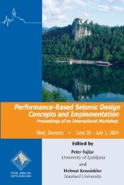
<strong>2007</strong> Undergraduate <strong>Seismic</strong> <strong>Design</strong><br />
<strong>Competition</strong> <strong>Rules</strong><br />
Fourth Annual <strong>Competition</strong><br />
Sponsored by:<br />
- Pacific Earthquake Engineering Research (<strong>PEER</strong>) Center<br />
- Multi-Disciplinary Center for Earthquake Engineering Research (MCEER)<br />
- Mid-America Earthquake (MAE) Center<br />
- Earthquake Engineering Research Institute (EERI)<br />
<strong>Competition</strong> Developed, Planned and Hosted by:<br />
<strong>PEER</strong>, MCEER, MAE Student Leadership Councils<br />
http://peer.berkeley.edu/students<br />
http://mceer.buffalo.edu/education/slc/<br />
http://mae.ce.uiuc.edu/graduate/slc_index.html
Table of Contents<br />
Page<br />
1.0 Introduction 2<br />
1.1 <strong>2007</strong> <strong>Competition</strong> Objectives 2<br />
1.2 Summary of Rule Changes 3<br />
1.3 Structural <strong>Design</strong> Objective 3<br />
1.4 Tentative <strong>Competition</strong> Schedule 4<br />
2.0 Overview of <strong>Rules</strong> and Eligibility Requirements 5<br />
3.0 Instrumentation and Data Processing 14<br />
3.1 Instrumentation 14<br />
3.2 Data Processing 15<br />
4.0 Structural Testing 17<br />
4.1 Shake Table 17<br />
4.2 Structural Weights at Floor Levels 17<br />
4.3 Accelerometer Placement 17<br />
5.0 Performance-Based Scoring Method 22<br />
5.1 Annual Income 22<br />
5.2 Annual Initial Building Cost 22<br />
5.3 Annual <strong>Seismic</strong> Cost 22<br />
6.0 Scoring 25<br />
6.1 Annual Income 25<br />
6.2 Oral Presentation 25<br />
6.3 Poster 25<br />
6.4 Architecture 26<br />
6.5 Workmanship 26<br />
6.6 Final Scoring 27<br />
7.0 Example Problem 28<br />
8.0 Special Awards 33<br />
9.0 Registration 34<br />
10.0 Expenses / Shipping 35<br />
11.0 Maps 36<br />
12.0 <strong>Competition</strong> Sponsors 37<br />
13.0 <strong>Competition</strong> History 41<br />
Undergraduate <strong>Seismic</strong> <strong>Design</strong> <strong>Competition</strong> 1
1.0 Introduction<br />
This section describes the competition objectives, the major rule changes for <strong>2007</strong><br />
and the structural design objective. A tentative competition schedule will be<br />
presented as well.<br />
1.1 <strong>2007</strong> <strong>Competition</strong> Objectives<br />
The objectives of this Fourth Annual Undergraduate <strong>Seismic</strong> <strong>Design</strong><br />
<strong>Competition</strong> sponsored by the three centers of earthquake research including<br />
<strong>PEER</strong>, MCEER and MAE are:<br />
• To provide civil engineering undergraduate students an opportunity to<br />
do a hands on project within a performance-based seismic design<br />
framework by designing and fabricating a cost effective frame<br />
structure that performs well under earthquake simulation.<br />
• To promote the study of earthquake engineering amongst<br />
undergraduates.<br />
• To build the awareness of the versatile activities at <strong>PEER</strong>, MCEER<br />
and MAE among the civil engineering students and faculty at the core<br />
universities as well as the general public in order to encourage nationwide<br />
participation.<br />
• To increase the attentiveness of the value and benefit of the Student<br />
Leadership Council (SLC) representatives and officers among the core<br />
universities for the recruitment and development of SLC, which is a<br />
key liaison between students and each of the three research centers.<br />
The competition will be held on February 8 th and 9 th , <strong>2007</strong> at the Universal<br />
City Hilton Hotel in Los Angeles, California. This event will be held in<br />
conjunction with the EERI Annual Meeting. Undergraduate teams are<br />
strongly encouraged to attend the sessions of this conference. More<br />
information about this conference is available online at: http://www.eeri.org<br />
Accommodations for competing teams will be provided on the nights of<br />
February 7 th , 8 th and 9 th at the Universal City Hilton Hotel.<br />
The competition will be open to teams from any university, and it will be<br />
organized by three earthquake engineering research centers, in the U.S.: the<br />
Pacific Earthquake Engineering Research Center (<strong>PEER</strong>), the<br />
Multidisciplinary Center for Earthquake Engineering Research (MCEER), and<br />
the Mid America Earthquake Engineering Research Center (MAE). <strong>PEER</strong> is<br />
headquartered at the University of California, Berkeley, MCEER is<br />
headquartered at the State University of New York, at Buffalo and MAE is<br />
headquartered at the University of Illinois at Urbana-Champaign. Only teams<br />
affiliated with one of the three research centers (<strong>PEER</strong>, MCEER or MAE) will<br />
be eligible for financial support from their respective center’s educational<br />
Undergraduate <strong>Seismic</strong> <strong>Design</strong> <strong>Competition</strong> 2
program, but the organizing committee encourages the participation of any<br />
team and to that end, will assist any team’s search for financial support to<br />
attend the competition.<br />
1.2 Summary of Rule Changes<br />
1.2.a Just as in the 2006 competition hosted by <strong>PEER</strong> and EERI, a<br />
performance based scoring method will be used, and is based on<br />
three primary components: annual income, annual initial building<br />
cost, and annual seismic cost. These three components will be<br />
used to calculate the structural performance, in terms of annual<br />
revenue. The team with the largest annual revenue will be the<br />
winning team. Details of each component are given in Sections 5<br />
and 6.<br />
1.2.b Detailed restrictions placed on damping devices are included<br />
section 2.9.i.<br />
1.2.c <strong>PEER</strong> will not ship the base and roof plates to each team before the<br />
competition. Rather, upon arrival, each team will receive their<br />
base and roof plates, at which time they may attach them to the<br />
structure. Further details are included in sections 2.10 and 2.11.<br />
1.2.d The annual income generated by rentable floor space has been<br />
reduced by roughly 30% and noted in section 5.1.<br />
1.2.e Sponsor names and logos are permitted on the structure in<br />
accordance with section 2.3.<br />
1.3 Structural <strong>Design</strong> Objective<br />
Your team has been hired to submit a design for a multi-level commercial<br />
office building. To verify the seismic load resistance system, a scaled model<br />
must be constructed from balsa wood and will be tested under severe<br />
earthquake simulation. Model structures shall be constructed at a scale of<br />
72:1. Structures will be tested on the UCIST unidirectional earthquake shake<br />
table, with plan dimensions of 45.7 cm by 45.7 cm (18.0 inch by 18.0 inch)<br />
and a payload capacity of 15.0 kg (33 lb). Structures should withstand scaled<br />
versions of ground motions recorded during the 1940 El Centro, 1994<br />
Northridge and 1995 Kobe earthquakes, which will be available online at the<br />
following website: http://peer.berkeley.edu/students/<strong>Seismic</strong>.html<br />
<strong>Seismic</strong> performance of the designated structure will be evaluated by<br />
monitoring the accelerations at the roof and on the shake table. Accelerations<br />
will be integrated, as discussed in Section 3.0, to obtain displacements. A<br />
structure that has a low peak drift ratio between the roof and the shake table is<br />
desired, as well as a low peak roof acceleration.<br />
Model dimension details are as specified:<br />
Maximum number of floor levels: 29 levels<br />
Minimum number of floor levels: 15 levels<br />
Maximum building plan dimensions: 39.4 cm (15.5 inch) square<br />
Undergraduate <strong>Seismic</strong> <strong>Design</strong> <strong>Competition</strong> 3
Minimum individual floor plan area: 232 cm 2 (36.0 inch 2 )<br />
Total building floor plan area (all floors): 1 m 2 to 3 m 2 (10.76 ft 2 to 32.3 ft 2 )<br />
Required floor height: 5.08 cm (2.00 inch), See section 6.4<br />
for tolerances<br />
Required lobby level height (1 st level): 10.2 cm (4.00 inch), See section 6.4<br />
for tolerances<br />
Maximum Model height:<br />
1.52 m (5 ft)<br />
Diaphragms (floors):<br />
Actual floors need not be<br />
constructed, beam members are<br />
adequate<br />
1.4 Tentative <strong>Competition</strong> Schedule<br />
The competition schedule presented below is subject to change. Teams will<br />
be notified of the final schedule in the weeks leading up to the event. See the<br />
competition website for updates to the competition schedule.<br />
Wednesday, February 7, <strong>2007</strong><br />
PM<br />
Long-distance-traveling teams arrive<br />
Thursday, February 8, <strong>2007</strong><br />
AM<br />
Short-distance-traveling teams arrive<br />
Noon – 1:00 PM Lunch (at Conference)<br />
1:00 – 3:00 PM Model Preparation (if needed)<br />
4:00 – 7:00 PM Team Presentations to public<br />
7:00 – 8:30 PM Dinner (at Conference)<br />
Friday, February 9, <strong>2007</strong><br />
8:00 – 9:00 AM Breakfast<br />
8:00 – 10:00 AM Model Inspection, and Weigh-In<br />
11:00 AM – noon Judging<br />
Noon – 1:00 PM Lunch (at Conference)<br />
1:00 – 6:00 PM Shake Table Testing<br />
7:00 – 8:30 PM Dinner (at Conference)<br />
Saturday, February 10, <strong>2007</strong><br />
10:00 – 10:30 AM Judges Meeting to Finalize Scores<br />
Noon – 1:00 PM Awards Ceremonies<br />
PM<br />
Return Travel<br />
NOTE: This schedule allows a lot of free time for participating students to take advantage<br />
of conference events, presentations and social functions.<br />
Undergraduate <strong>Seismic</strong> <strong>Design</strong> <strong>Competition</strong> 4
2.0 Overview of <strong>Rules</strong> and Eligibility Requirements<br />
2.1 Eligibility:<br />
The following rules shall be strictly followed:<br />
2.1.a<br />
Participants must be currently enrolled undergraduate students and<br />
may come from any university in the USA or internationally.<br />
Undergraduate teams from schools associated with <strong>PEER</strong>, MCEER<br />
or MAE are eligible for financial support from their respective<br />
center. For teams from schools unassociated with <strong>PEER</strong>, MCEER<br />
or MAE who wish to enter and desire assistance in finding<br />
financial support, the organizing committee will assist the search<br />
for funding.<br />
2.1.b Teams may have as many undergraduate student participants as<br />
they wish; however, for <strong>PEER</strong>, MCEER and MAE affiliated<br />
schools, the expenses (travel, lodging, etc) of only a certain<br />
number of students will be covered by the center. This number<br />
will be determined after the registration deadline and announced to<br />
all registered teams.<br />
2.1.c<br />
Each competing university can enter one student team and one<br />
structure at the competition.<br />
2.1.d Completed registration and preliminary structural plans must be<br />
submitted by November 30 th , 2006. See section 6.0 for registration<br />
details.<br />
2.1.e<br />
The following universities are eligible to enter one team:<br />
<strong>PEER</strong> Core Institutions:<br />
University of California, Berkeley<br />
University of California, Davis<br />
University of California, Irvine<br />
University of California, Los Angeles<br />
University of California, San Diego<br />
California Institute of Technology<br />
Stanford University<br />
University of Southern California<br />
University of Washington<br />
<strong>PEER</strong> Affiliate Institutions:<br />
California Polytechnic State University, San Luis Obispo<br />
California State University, Los Angeles<br />
California State University, Northridge<br />
San Jose State University<br />
University of Hawaii<br />
Oregon State University<br />
MCEER Affiliated Institutions<br />
California State University, Los Angeles<br />
City University of New York<br />
Cornell University<br />
Undergraduate <strong>Seismic</strong> <strong>Design</strong> <strong>Competition</strong> 5
Florida A&M University<br />
New Jersey Institute of Technology<br />
Pennsylvania State University<br />
University of British Columbia<br />
State University of New York, Buffalo<br />
University of California, Irvine<br />
University of California, Los Angeles<br />
University of Colorado, Boulder<br />
University of Illinois, Urbana-Champaign<br />
University of Nevada, Reno<br />
University of Southern California<br />
University of Wisconsin, Green Bay<br />
MAE Affiliated Institutions<br />
Georgia Institute of Technology<br />
Texas A&M University<br />
University of Illinois, Urbana-Champaign<br />
University of Memphis<br />
University of Michigan<br />
University of Puerto Rico, Mayagüez<br />
University of Texas, Austin<br />
Washington University<br />
2.2 There is no limit to the number of sponsors supporting the materials supplied,<br />
transportation, and other expenses.<br />
2.3 If financial assistance was provided by external sponsors, those sponsors’<br />
names and/or logos may appear on the structure or on any clothing worn by<br />
the team. However, it should be below the school name, which is at the top of<br />
the structure, as described in section 2.4.<br />
2.4 The university name should be placed at the top of the structure, on a banner<br />
or paper (non-structural element). The size of this banner shall not exceed a<br />
length of 6 inch and a height of 1 inch.<br />
2.5 The structure shall be constructed prior to competition. No structural<br />
modifications will be allowed at the competition. If a structure is damaged in<br />
transport, it may be repaired to its original design at the competition.<br />
2.6 Participating teams are responsible for transportation of their structure to and<br />
from the competition site. Transportation of structure should be considered in<br />
the design and construction of the model. See Section 8.0 for transportation<br />
details.<br />
Undergraduate <strong>Seismic</strong> <strong>Design</strong> <strong>Competition</strong> 6
2.7 <strong>PEER</strong> will be responsible for selecting three to five judges from the structural<br />
and earthquake engineering industry and academia to score all aspects at the<br />
competition.<br />
2.8 Judges will determine the direction of shaking on the structure.<br />
2.9 Structural Model<br />
2.9.a<br />
Structures shall be made of balsa wood. Columns may have a<br />
maximum cross section of 6.4 mm (1/4 inch) by 6.4 mm (1/4 inch).<br />
Beams may have a maximum cross section of 6.4 mm (1/4 inch)<br />
by 3.2 mm (1/8 inch). Built up beams or columns, consisting of<br />
two or more balsa wood members glued together, are not<br />
permitted. Circular balsa wood columns are permitted with a<br />
diameter up to 6.4 mm (1/4 inch).<br />
2.9.b Allowable lateral force resisting systems include: x bracing,<br />
diagonal bracing, eccentric bracing, moment connections, and<br />
shear walls.<br />
2.9.c Diagonal bracing elements, including x-braces, shall be<br />
constructed only in vertical planes, in the North-South, or East-<br />
West directions. A brace in a three dimensional space will not be<br />
allowed and will result in no income for the space. Braces in three<br />
dimensional space will be allowed only if used on an exterior<br />
portion of the structure with such three dimensional geometry.<br />
2.9.d Shear walls constructed of balsa wood with a thickness not<br />
exceeding 3.2 mm (1/8 inch) are allowed. Shear walls must have a<br />
minimum length of 25.4 mm (1.00 inch). Shear wall height is not<br />
restricted. Columns can be attached to the ends of a shear wall.<br />
2.9.e<br />
2.9.f<br />
Moment frame connections are allowed. The height and length of<br />
such connections shall not exceed 3 times the maximum cross<br />
sectional dimension (width or thickness) of the members being<br />
joined, as shown in Figure 2-1. The thickness shall not exceed the<br />
minimum cross sectional dimension of the members being joined.<br />
The interior building core, usually reserved for elevators,<br />
emergency exit staircases, and utilities, etc, can still be considered<br />
as "usable floor space" ONLY IF the braces, shear walls and<br />
columns do not block the access to it. To be specific, for each<br />
floor, a minimum of one access opening in the E-W direction and a<br />
minimum of one access opening in the N-S direction are required.<br />
Each access opening should have minimum model dimensions of<br />
25.4 mm (1.00 inch) width by 38.1 mm (1.50 inch) height. The<br />
model will need adequate space at floors which will have a weight<br />
installed through it during shaking. See section 2.13 for details of<br />
added dead weight.<br />
2.9.g Each structure shall be constructed at a scale of 72:1. This<br />
corresponds to a prototype scale floor height of 3.66 m (12 ft) and<br />
a model scale floor height of 50.8 mm (2 inch).<br />
Undergraduate <strong>Seismic</strong> <strong>Design</strong> <strong>Competition</strong> 7
2.9.h Floor level diaphragms need not be constructed. Weights, to be<br />
attached at the competition, will simulate the dead load of floor<br />
diaphragms, office walls, furniture, and live load.<br />
2.9.i<br />
2.9.j<br />
Structural damping devices, such as viscous dampers, are allowed<br />
in the design.<br />
2.9.i.1 A damper will be included in the weight of the structure.<br />
Any material is allowed to manufacture a mass damper.<br />
The implementation of such a device needs to allow for the<br />
placement of weights as discussed in Sections 2.14 and 4.2.<br />
Damper attachments to the structure may not reinforce any<br />
other structural connections.<br />
2.9.i.2 Teams should consider that damping devices installed in 3-<br />
dimensional space (not in the same plane as an existing<br />
wall) will reduce rentable floor space as the dampers render<br />
the space unusable.<br />
2.9.i.3 Limits on the dimensions of column and beam cross<br />
sections are outlined in section 2.9.a. Dampers may be<br />
connected to beams or columns, but a single damper-tostructure<br />
connection may not be made to both a beam and a<br />
column.<br />
2.9.i.3.1<br />
2.9.i.3.2<br />
2.9.i.3.3<br />
If a damper is connected to a column, the<br />
column’s cross-section may not be increased<br />
beyond the limits in section 2.9.a by the<br />
connection.<br />
If a damper is connected to a beam, the beam’s<br />
cross-section may not be increased beyond<br />
twice the limits listed in section 2.9.a. That is to<br />
say that if a beam is constructed of 1/8” X 1/4”<br />
balsawood section, the damper connection may<br />
expand the cross-section of the beam to 1/4” X<br />
1/4”.<br />
The length of the connections described above,<br />
in the direction of the connected beam or<br />
column, may not exceed 1 inch.<br />
Connections of structural members can be made only from wood<br />
glue. Connections of structural members to the base plate or to the<br />
roof plate can be made using wood glue or hot glue.<br />
2.9.k The connection between the base board and first level columns<br />
should be carefully designed to prevent uplift (or separation of the<br />
columns from the base board).<br />
2.10 Structural Model Base Plate<br />
2.10.a A plywood base plate will be used to attach the structure to the<br />
shaking table, and will be fabricated to the provided specifications<br />
by the Organizing Committee. Upon arrival at the competition,<br />
Undergraduate <strong>Seismic</strong> <strong>Design</strong> <strong>Competition</strong> 8
each team will receive their base plate and may then attach it to the<br />
already-built structure.<br />
2.10.b An engineering diagram depicting the manufactured base plate is<br />
shown in Figure 2-2.<br />
2.11 Structural Model Roof Plate<br />
2.11.a A plywood roof plate will be used to attach the accelerometer to<br />
the structure, and will be fabricated to the provided specifications<br />
by the Organizing Committee. Upon arrival at the competition,<br />
each team will receive their roof plate and may then attach it to the<br />
already-built structure.<br />
2.11.b The roof plate will be a plywood plate of thickness 7.62 mm (3/8<br />
inch) with dimensions of 152 mm by 152 mm (6 inch by 6 inch).<br />
The plate will have four 6.35 mm (1/4 inch) diameter holes drilled<br />
at 12.7 mm (5 inch) on center to allow for attachment of<br />
accelerometer, using bolts, as shown in Figure 4-4. Teams will<br />
need to ensure total access to all four holes to allow attachment of<br />
weighted mass and accelerometer to roof plate.<br />
2.12 Structure Dimensions<br />
2.12.a The maximum base plan dimension of the structure shall be 45.7<br />
cm (15.5 inch) square.<br />
2.12.b The minimum plan area for any single floor is 232 cm 2 (36.0<br />
inch 2 ).<br />
2.12.c No floor plan area shall exceed the floor plan area of the level<br />
beneath.<br />
2.12.d Structural height is limited to 1.52 m (5 ft). Structural height shall<br />
be measured from the top of the base floor to the uppermost beam<br />
member of the top level. The base floor is defined as the top of the<br />
base plate<br />
2.13 Structural Loading<br />
2.13.a A dead load of 1.02 kg (2.25 lb) will be placed on floors at<br />
increments of one eighth of the structural height (H/8). The dead<br />
load (weights) will be placed starting at floor levels corresponding<br />
to (1/8) * H up to (7/8) * H. In cases where a floor does not exist<br />
at an exact increment of H/8, the weight will be attached to the<br />
nearest higher floor.<br />
2.13.b Dead loads to be placed at increments of H/8 will consist of a<br />
threaded bar, with a length of 914 mm (36.0 inch), and a diameter<br />
of 12.7 mm (1/2 inch). Each threaded bar will have washers and<br />
nuts to generate a weight of 1.02 kg (2.25 lb) at the floor level.<br />
2.13.c Weights will be attached to the frame in the direction<br />
perpendicular to shaking. Vertical weight connection members<br />
(columns) will be needed on all four sides of the structure, since<br />
judges will decide the direction of shaking. See Figure 4-3 for a<br />
Undergraduate <strong>Seismic</strong> <strong>Design</strong> <strong>Competition</strong> 9
typical weight attachment. Note that some moderate compressive<br />
force is required to secure the weights from moving relative to the<br />
structure during shaking and the structures should be designed to<br />
accommodate these compressive forces and should provide support<br />
so that the threaded rods do not move relative to the structure<br />
during shaking.<br />
2.13.d A dead load of 1.59 kg (3.5lb), including the accelerometer, will be<br />
placed at the roof level. The weight will consist of a steel plate<br />
with dimensions of 15.24 cm by 15.24 cm by 1.27 cm (6 inch by 6<br />
inch by 0.5 inch), with a weight of 0.45 kg (3.0 lbs), and the<br />
accelerometer, which weighs 0.23 kg (0.5 lbs). See Figure 4-4 for<br />
roof configuration.<br />
2.14 Mass of the structural model, including the base and roof plate and any<br />
damping devices, should not exceed 6.24 kg (13.75 lb). The payload<br />
capacity of the shake table is 15.0 kg (33 lb), and approximately 8.73 kg<br />
(19.25 lb) of weights will be attached to the floors and roof, leaving 6.24<br />
kg (13.75 lb) as a maximum allowable structural mass.<br />
2.15 The structural finish must be bare wood. Paint or other coatings will not<br />
be allowed on the structure.<br />
2.16 Scaled Earthquake Ground Motion Records to be used for the testing can<br />
be downloaded from: http://peer.berkeley.edu/students/<strong>Seismic</strong>.html<br />
2.17 Questions should be directed to the <strong>PEER</strong> student leadership council<br />
(SLC) via email to: seismic.design.competition@gmail.com<br />
2.18 In the Spirit of the <strong>Competition</strong>, the Judges and/or SLC may take<br />
disciplinary action, including warnings, point deductions, or<br />
disqualification of a team or entry for inappropriate use of materials,<br />
language, alcohol, uncooperativeness, or general unprofessional behavior<br />
of team members or persons associated with a team. The judges have the<br />
final authority to determine what constitutes a violation of the “spirit of<br />
the competition” and may take appropriate action towards point deduction<br />
or disqualification.<br />
2.19 Oral Presentation<br />
2.19.a Each team will give a five minute oral presentation to a panel of<br />
judges. Judges will have 5 minutes to ask questions following the<br />
presentation. Presentations will be open to the public.<br />
2.19.b Presentations should review the structural design, lateral force<br />
resisting system, performance prediction, and any other details of<br />
relevance.<br />
2.19.c An LCD projector and laptop, running Microsoft Windows XP,<br />
and PowerPoint (Office XP) will be provided.<br />
Undergraduate <strong>Seismic</strong> <strong>Design</strong> <strong>Competition</strong> 10
2.19.d Teams will be allowed to run presentations from their own laptops.<br />
However, it is strongly recommended that presentations be brought<br />
on a USB memory stick and/or CD-ROM in case of technical<br />
difficulties with the LCD projector.<br />
2.19.e Judges will determine the order for team presentations and<br />
structural testing by random draw.<br />
2.20 Poster<br />
2.20.a A poster shall be displayed to show the structural design (plan<br />
view, elevation views, and 3D views – if generated), performance<br />
prediction, economics, project management, and any other relevant<br />
details.<br />
2.20.b The university name and <strong>PEER</strong> and EERI logos should appear at<br />
the top of the poster.<br />
2.20.c Posters shall have a height of 1.1 m (42 inch) and a width of 0.91<br />
m (36 inch).<br />
2.20.d A minimum font size of 20 is recommended for general text, and a<br />
font size of 40 for the university name.<br />
2.21 A unique architectural form and quality workmanship is highly desired by<br />
the owner, as shown in Figure 2-3. See Scoring Section 6.<br />
Figure 2-1: Allowable Moment Frame Connection Detail<br />
Undergraduate <strong>Seismic</strong> <strong>Design</strong> <strong>Competition</strong> 11
9.75 in o.c. 4.125 in o.c.<br />
.875 in<br />
15.5 in<br />
15.5 inch square<br />
building footprint<br />
16.25 in<br />
15.5 in<br />
18 in<br />
3/4 inch holes<br />
3/8 inch thick<br />
plywood base<br />
plate outline<br />
18 in<br />
Figure 2-2: Engineering drawing of base plate to be distributed to teams upon arrival at<br />
the competition.<br />
Undergraduate <strong>Seismic</strong> <strong>Design</strong> <strong>Competition</strong> 12
Figure 2-3 Structural/Architectural Concepts<br />
Undergraduate <strong>Seismic</strong> <strong>Design</strong> <strong>Competition</strong> 13
3.0 Instrumentation and Data Processing<br />
This section describes the instrumentation setup used to collect the acceleration data,<br />
and the methods of data processing used to obtain transient displacements from the<br />
recorded accelerations.<br />
3.1 Instrumentation<br />
Horizontal acceleration will be measured in the direction of shaking using<br />
accelerometers mounted on the roof of the structure and on the base shaker<br />
(Fig. 3-1).<br />
⎛ Δ<br />
Roof<br />
− Δ<br />
Floor<br />
⎞<br />
EDP1<br />
= max⎜<br />
⎟<br />
H<br />
⎝<br />
⎠<br />
EDP2<br />
= max RoofAcceleration<br />
Figure 3-1: Schematic of instrumentation layout and measured engineering demand<br />
parameters for structure without base isolation.<br />
Undergraduate <strong>Seismic</strong> <strong>Design</strong> <strong>Competition</strong> 14
ΔRoof - ΔFloor<br />
Roof<br />
Roof<br />
Acceleration<br />
Individual columns may<br />
not be base isolated.<br />
All columns must be<br />
bolted to a continuous<br />
floor plate.<br />
Base (Shake Table)<br />
Base Plate<br />
Base<br />
Acceleration<br />
Figure 3-2: Schematic of a structure with base isolation used for individual columns.<br />
Such configurations are not allowed.<br />
Technical specifications of the shaker table, data acquisition system and<br />
accelerometers can be found at http://peer.berkeley.edu/students/<strong>Seismic</strong>.html.<br />
3.2 Data Processing<br />
Displacements will be computed from recorded each acceleration time series<br />
by performing the following steps:<br />
1. Transfer the acceleration records into the frequency domain using a Fourier<br />
transform.<br />
2. Digitally high-pass filter the acceleration recordings in the frequency domain<br />
using a 3 rd order Butterworth filter with a corner frequency of 0.8 Hz.<br />
3. Double integrate the filtered acceleration records over time to obtain<br />
displacements.<br />
A portion of the low-frequency range of the raw acceleration signals must be<br />
removed using a digital filter prior to double integration because the low<br />
frequency content of the signals is small compared with the noise in the<br />
signals. Highly unrealistic displacements would be obtained if the raw data<br />
were integrated in time without first filtering off some of the low frequency<br />
content because of the low-frequency noise. An undesired but unavoidable<br />
consequence of the filtering is that the low-frequency portion of the<br />
acceleration signals, which contains permanent displacements, must be<br />
removed. As a result, the displacements computed by double-integrating the<br />
acceleration records are transient displacements; the low-frequency<br />
Undergraduate <strong>Seismic</strong> <strong>Design</strong> <strong>Competition</strong> 15
permanent component will not be reflected in the computed displacement<br />
time series.<br />
Undergraduate <strong>Seismic</strong> <strong>Design</strong> <strong>Competition</strong> 16
4.0 Structural Testing<br />
This section will present an overview of the structural testing requirements. Details<br />
for the shake table, weights placed at floor levels, roof weight, and accelerometers<br />
will be presented<br />
4.1 Shake Table<br />
The unidirectional earthquake shake table to be used for testing has the<br />
dimensions and bolt hole pattern as shown in Figure 4-1. Shake table payload<br />
capacity is 15.0 kg (33 lb).<br />
4.2 Structural Weights at Floor Levels<br />
Details for the threaded bar weights are discussed in Section 2.13. It is<br />
strongly recommended that your team purchase a sample weight to ensure<br />
proper attachment and fit to your structure at the competition. Additional<br />
vertical members (columns) at the location of weights will be needed, as<br />
shown in Figures 4-2 and 4-3. The weights must be secured from translation<br />
that might occur during shaking. Weights cannot be secured to the beam<br />
alone. Weights will be secured to the structure using nuts and washers, as<br />
discussed in Section 2.13. Weights will be hand tightened to the structure;<br />
this will result in a potential inward deformation of the exterior frame, if the<br />
weight location is not braced with beams, as shown in Figure 4-3.<br />
4.3 Accelerometer Placement<br />
Two accelerometers will be utilized in the competition. For each structure,<br />
one accelerometer will be attached to the shake table (on the bottom), and one<br />
accelerometer will be placed at the roof level.<br />
Undergraduate <strong>Seismic</strong> <strong>Design</strong> <strong>Competition</strong> 17
457 mm<br />
(18 inch)<br />
4.76 mm<br />
(3/16 inch)<br />
diameter hole<br />
457 mm<br />
(18 inch)<br />
4.76 mm (3/16 inch)<br />
diameter threaded holes<br />
located at 82.6 mm (3.25<br />
inch) center to<br />
82.6 mm<br />
(3.25 inch)<br />
82.6 mm<br />
(3.25 inch)<br />
(a.) Plan View of Shake Table<br />
(b.) Photograph of Shake Table and Operation PC (Data Acquisition not shown)<br />
Figure 4-1: University Consortium for Instructional Shake Tables (UCIST) Earthquake<br />
Undergraduate <strong>Seismic</strong> <strong>Design</strong> <strong>Competition</strong> 18
Typical Floor Elevation View<br />
Washer<br />
Nut<br />
Extra vertical members (columns)<br />
to allow for support of threaded<br />
bar, washer and nut<br />
Column<br />
Beam<br />
Threaded Bar<br />
Typical Floor Plan View<br />
Nut<br />
Washer<br />
Threaded Bar<br />
Nut and washers<br />
will be tightened<br />
by hand to secure<br />
weights for testing<br />
– this will cause<br />
the frame to<br />
deflect inwards, if<br />
not properly<br />
braced<br />
Column<br />
Direction of<br />
shaking (to<br />
be decided<br />
by judges)<br />
Recommended<br />
locations for extra<br />
beams to prevent<br />
deflection of frame<br />
due to clamping<br />
action of weight<br />
attachment<br />
Figure 4-2: Anchorage of Weights to Structure<br />
Undergraduate <strong>Seismic</strong> <strong>Design</strong> <strong>Competition</strong> 19
(a.) Example of insufficient support for threaded bars that prevents the requisite<br />
tightening of the nuts, thereby permitting the bars to move relative to the structure<br />
during shaking. Vertical columns at the location of threaded bars would have<br />
facilitated weight attachment, including tightening of the nuts to prevent rolling<br />
and sliding of the bars during shaking.<br />
Accelerometer<br />
Vertical Columns at Threaded<br />
Bar Locations<br />
Threaded Bar Weights (2005<br />
<strong>Competition</strong>)<br />
(b.) Example of an ideal support for threaded bars. Vertical columns facilitated weight<br />
attachment, and prevented rolling and sliding of the bars during shaking. Photo taken at<br />
2005 competition, which had a different threaded bar weight distribution than 2006.<br />
Figure 4-3: Typical Weight Attachment<br />
Undergraduate <strong>Seismic</strong> <strong>Design</strong> <strong>Competition</strong> 20
Roof Elevation View<br />
Bracing scheme not shown<br />
Roof Plan View<br />
Note: roof plate will<br />
need to be attached at<br />
the center of the roof<br />
to ensure even weight<br />
distribution.<br />
0.25 in diameter holes<br />
5.0 in<br />
6.0 in<br />
5.0 in<br />
6.0 in<br />
Steel Plate<br />
Figure 4-4: Weight and Accelerometer at Roof Level<br />
Undergraduate <strong>Seismic</strong> <strong>Design</strong> <strong>Competition</strong> 21
5.0 Performance-Based Scoring Method<br />
This section describes the performance-based method used to score the seismic<br />
performance of the structures in the seismic competition. The method consists of<br />
three primary components: 1. Annual income, 2. Annual initial building cost, and 3.<br />
Annual seismic cost. The final measure of structural performance is the annual<br />
revenue, computed as annual income minus annual building construction cost minus<br />
annual seismic cost. An example problem in Section 7.0 demonstrates the scoring<br />
method.<br />
5.1 Annual Income<br />
Annual building income will be based on useable floor space, with higher<br />
floors bringing in more income than lower floors as follows:<br />
$250 per year per square inch for floors 1 through 15.<br />
$350 per year per square inch for floors between 16 through 24.<br />
$450 per year per square inch for floors 25 and taller .<br />
5.2 Annual Initial Building Cost<br />
The cost of the building will be the cost of the land beneath the building<br />
footprint plus the cost of the structure. The cost of land is $35,000 per square<br />
inch of building footprint. Building footprint is defined as the floor plan area<br />
of the first level (note that no level can exceed the floor plan area of the first<br />
level). The initial cost of the building is $10,000,000 per kilogram of building<br />
mass. The building mass includes the mass of the structure and any energy<br />
dissipation devices (e.g. viscous dampers). Building mass will not include the<br />
mass of the base and roof plate or threaded bars. The mass of these<br />
aforementioned items is known and will be subtracted from the mass<br />
measured at the competition. The annual building construction cost will be<br />
computed by dividing the cost of land and the initial cost of the building by<br />
the design life of the building (100 years).<br />
5.3 Annual <strong>Seismic</strong> Cost<br />
The structures will be subjected to a series of three ground motions with<br />
increasing intensity. Small design ground motions occur more frequently than<br />
large design ground motions, and the frequency with which each ground<br />
motion is anticipated to occur is represented by its return period (Table 5-1).<br />
Undergraduate <strong>Seismic</strong> <strong>Design</strong> <strong>Competition</strong> 22
Table 5-1: Return periods for ground<br />
motions used in competition.<br />
Motion Return Period<br />
(Years)<br />
El Centro 50<br />
Northridge 150<br />
Kobe 200<br />
Economic damage from each earthquake will be assessed using loss functions<br />
that relate dollar loss to different engineering demand parameters (EDP's) that<br />
will be measured when the structures are shaken with the ground motions.<br />
The EDP's are:<br />
• EDP1 = Peak absolute value of drift ratio between the roof and floor of the<br />
structure.<br />
• EDP2 = Peak of absolute value of roof acceleration.<br />
The engineering demand parameters are illustrated schematically in Figure 3-<br />
1. Annual economic damage for a given motion will be computed by<br />
summing the economic loss for each EDP for that motion, and then dividing<br />
by that motion's return period. Annual seismic economic damage will be<br />
computed by summing the annual economic damage for the three ground<br />
motions imposed. Each loss function is discussed in detail in the sections that<br />
follow.<br />
5.3.a<br />
Loss Caused by Structural Damage (EDP1)<br />
Structural damage to the buildings will be correlated with the peak<br />
drift ratio between the roof and the first floor [Drift Ratio = (Δ Roof<br />
– Δ Floor )/H]. The maximum cost of repairing structural damage<br />
will be assumed equal to the initial construction cost of the<br />
structure (does not include the cost of land, only the cost of the<br />
structure itself). The loss function relating cost of structural<br />
damage to drift ratio will be defined as a cumulative normal<br />
probability density function with mean drift ratio of 0.04 and<br />
standard deviation of 0.01. The distribution function can be<br />
computed using many commercially-available software packages<br />
(e.g. the NORMDIST function in Microsoft Excel, with the<br />
'cumulative' field set to TRUE). The function is plotted in terms of<br />
normalized cost in Figure 5-1.<br />
Undergraduate <strong>Seismic</strong> <strong>Design</strong> <strong>Competition</strong> 23
Structure Repair Cost /<br />
Initial Structural Cost<br />
1<br />
0.8<br />
0.6<br />
0.4<br />
0.2<br />
0<br />
0 0.02 0.04 0.06 0.08<br />
Peak Drift Ratio<br />
max |(Δ Roof<br />
- Δ Floor<br />
)/H|<br />
Figure 5-1: Loss function relating structural replacement cost to peak drift ratio.<br />
5.3.b Loss Caused by Equipment Damage (EDP2)<br />
The structure will house equipment with a total value of<br />
$20,000,000 that is sensitive to structural acceleration. Damage to<br />
this equipment will be related to the peak of the absolute value of<br />
roof acceleration using a loss function that is a cumulative normal<br />
probability density function with mean peak roof acceleration of<br />
1.5 g, and standard deviation of 0.5 g. The loss function is plotted<br />
in Figure 5-2.<br />
Equipment Cost ( x$10 6 )<br />
20<br />
16<br />
12<br />
8<br />
4<br />
0<br />
0 1 2 3<br />
max |Roof Acceleration| (g)<br />
Figure 5-2: Loss function relating equipment cost to peak roof acceleration.<br />
Undergraduate <strong>Seismic</strong> <strong>Design</strong> <strong>Competition</strong> 24
6.0 Scoring<br />
The following section will describe the procedure to generate the overall final<br />
competition score. The final competition score will depend on the annual revenue, as<br />
determined from Section 5.0, the oral presentation, the poster, workmanship of<br />
structure, and architecture of structure. Scores in terms of an annual revenue will be<br />
assigned for the oral presentation and poster. The final competition score will be in<br />
terms of annual revenue, hence the team with the greatest annual revenue will be the<br />
winning team.<br />
6.1 Annual Income<br />
As determined by performance and rental income described in Section 5.0.<br />
6.2 Oral Presentation<br />
A maximum of 5 team members will be eligible to give the 5 minute<br />
presentation. The oral presentation, as discussed in Section 2.19, will be<br />
assigned a score based on annual revenue. A high quality oral presentation<br />
will give your team the reputation as being one of the top structural firms.<br />
The building owner will get to “brag” that your high quality team did the<br />
structural design for his/her building, and charge higher rents.<br />
The presentations will be given a scored from 0 to 10. A score of 10 is best<br />
while a score of 0 is a very poor presentation. The annual income will then be<br />
multiplied by the score as a percentage. A complete breakdown of annual<br />
income increases for presentations is shown in the Table 6-1. For example, a<br />
presentation score of 8 will increase the annual income by 8%, etc.<br />
Annual Income<br />
Score<br />
Increase, X<br />
10 10%<br />
9 9%<br />
8 8%<br />
7 7%<br />
6 6%<br />
5, etc. 5%, etc<br />
Table 6-1: Annual Income Increase for Oral Presentations.<br />
6.3 Poster<br />
The poster, as discussed in Section 2.20, will be assigned a score based on<br />
annual revenue. A high quality poster will have a similar effect as a high<br />
quality presentation. A complete breakdown of annual income increases for<br />
posters is shown in the Table 6-2.<br />
Undergraduate <strong>Seismic</strong> <strong>Design</strong> <strong>Competition</strong> 25
Annual Income<br />
Score<br />
Increase, Y<br />
10 10%<br />
9 9%<br />
8 8%<br />
7 7%<br />
6 6%<br />
5, etc. 5%, etc<br />
Table 6-2: Annual Income Increase for Posters.<br />
6.4 Architecture<br />
A unique architectural design is highly desired by the owner. The architecture<br />
of the model, as discussed in Section 2.21, will be assigned a score based on<br />
annual revenue. Like the poster and presentation, an aesthetically pleasing<br />
structure will have a similar effect as a high quality presentation. Vice-versa,<br />
a rectangular box-like structure will receive a low architectural score. A<br />
complete breakdown of annual income increases for architecture is shown in<br />
the Table 6-3.<br />
Annual Income<br />
Score<br />
Increase, Z<br />
10 10%<br />
9 9%<br />
8 8%<br />
7 7%<br />
6 6%<br />
5, etc. 5%, etc<br />
Table 6-3: Annual Income Increase for Architecture<br />
6.5 Workmanship<br />
The distance between any two floors, center to center, should be:<br />
Lobby Floor Height = 4in +/- 3/16in<br />
Floor spacing = 2in +/- 3/16in .<br />
The total height of the building, from top of base board to bottom of roof plate,<br />
should be:<br />
Building Height = (2*number of floors + 2in) +/- 3/8 in.<br />
Failure to comply with dimensional tolerances will result in increased building<br />
costs according to the following criteria:<br />
M = +2% of total building cost per 3/16 inch per floor height deviation from<br />
specified dimension<br />
Undergraduate <strong>Seismic</strong> <strong>Design</strong> <strong>Competition</strong> 26
N = +5% of total building cost per 3/8 inch building height deviation from<br />
specified dimension<br />
Heights between dimensional increments will be rounded to the next increment.<br />
For example, a floor height of 2.3 in will receive a building costs increase of M =<br />
+2%, and a building height of 50.7 in, when the design height was 50.0 inch, will<br />
receive an increase of N = +5%.<br />
6.6 Final Scoring<br />
The final score will be in terms of annual revenue, ideally a profit. The team<br />
with the greatest final annual building revenue will be the winning team.<br />
Annual building revenue will be the final annual income minus final annual<br />
building cost and final annual seismic cost.<br />
Final Annual Income, FAI, can be stated as:<br />
FAI = (1+X+Y+Z) * AI<br />
Where:<br />
AI: Annual Income<br />
X: Annual Income Increase from Presentation<br />
Y: Annual Income Increase from Poster<br />
Z: Annual Income Increase from Architecture<br />
Final Annual Building Cost, FABC, can be stated as:<br />
Where:<br />
FABC = (1+M+N) * ABC<br />
ABC: Annual Building Cost<br />
M: Annual Building Cost Increase from inadequate tolerances on floor<br />
height<br />
N: Annual Building Cost Increase from inadequate tolerances on total<br />
height<br />
Final Annual <strong>Seismic</strong> Cost, FASC, can be stated as:<br />
FASC = Annual <strong>Seismic</strong> Cost<br />
The Final Annual Building Revenue, FABR, can be stated as:<br />
FABR = (1+X+Y+Z) * AI - (1+M+N) * ABC - FASC<br />
= FAI-FABC-FASC<br />
Undergraduate <strong>Seismic</strong> <strong>Design</strong> <strong>Competition</strong> 27
7.0 Example Problem<br />
It should be noted that allowable building footprint dimensions from 2004 differ than<br />
those required by this year’s competition.<br />
In this section, the performance of the structure from the UCSD team from the 2004<br />
<strong>PEER</strong> seismic competition will be computed to demonstrate the performance-based<br />
scoring system. Data for the structure can be downloaded from<br />
http://peer.berkeley.edu/students/<strong>Seismic</strong>.html.<br />
7.1 Annual Income<br />
The structure was 15 stories tall, and the useable floor area was 2.8 m 2 (4,340<br />
inch 2 ). The annual income per square meter is $250 since all of the floors are<br />
lower than 1 meter. Hence, the income for the building is (4,340 in 2 )·($250 /<br />
in 2 / year) = $1,085,000 / year.<br />
7.2 Annual Initial Building Cost<br />
The structure occupied a footprint area of 0.21 m 2 (324 inch 2 ). Hence, the<br />
cost of land beneath the building was (324 in 2 ) · ($35,000 / in 2 ) =<br />
$11,340,000. Divided by the design life of the structure, the annual cost of<br />
land is ($11,340,000) / (100 years) = $113,400 / year.<br />
7.3 Annual <strong>Seismic</strong> Cost<br />
The mass of the structure was 1.5 kg (3.3 lb). Hence, the initial construction<br />
cost was (1.5 kg) · ($10,000,000 / kg) = $15,000,000. Divided by the design<br />
life of the structure, the annual cost of the building is ($15,000,000) / (100<br />
years) = $150,000 / year.<br />
The annual initial building cost is the sum of the cost of the land and the cost<br />
of the building, which is $113,400 / year + $150,000 / year = $263,400 / year.<br />
The time series from which the EDP's are computed are shown in Figs. 7-1<br />
through 7-3 for the three earthquake motions. The structure did not utilize<br />
base isolation, so there is zero displacement between the floor and the base.<br />
The EDP's are summarized in Table 7-1.<br />
Undergraduate <strong>Seismic</strong> <strong>Design</strong> <strong>Competition</strong> 28
Drift Ratio<br />
0.02<br />
0.01<br />
0<br />
-0.01<br />
-0.02<br />
EDP1 = 0.014<br />
Roof<br />
Acceleration (g)<br />
1<br />
0.5<br />
0<br />
-0.5<br />
-1<br />
EDP2 = 0.91 g<br />
Figure 7-1: Time series for the 2004 UCSD structure during the El Centro motion.<br />
Drift Ratio<br />
0.03<br />
0<br />
-0.03<br />
EDP1 = 0.023<br />
Roof<br />
Acceleration (g)<br />
2<br />
1<br />
0<br />
-1<br />
-2<br />
EDP2 = 1.62 g<br />
0 6 8<br />
Time (s)<br />
Figure 7-2:: Time series for the 2004 UCSD structure during the Northridge motion.<br />
0.03<br />
Drift Ratio<br />
0<br />
-0.03<br />
EDP1 = 0.023<br />
Roof<br />
Acceleration (g)<br />
2<br />
1<br />
0<br />
-1<br />
-2<br />
EDP2 = 1.90 g<br />
0 6 8<br />
Time (s)<br />
Figure 7-3: Time series for the 2004 UCSD structure during the Kobe motion.<br />
Undergraduate <strong>Seismic</strong> <strong>Design</strong> <strong>Competition</strong> 29
Engineering Demand Parameter (EDP)<br />
Motion<br />
Max |Drift Ratio|<br />
(EDP1)<br />
Max |Roof Acc| (g)<br />
(EDP2)<br />
El Centro 0.014 0.91<br />
Northridge 0.023 1.62<br />
Kobe 0.023 1.90<br />
Table 7-1: Engineering demand parameters measured during ground motions for<br />
example structure.<br />
The seismic costs for each ground motion computed from the EDP's in Table 7-1<br />
are shown in Figure 7-4. The values are also summarized in Table 7-2, along<br />
with the annual seismic cost for each EDP obtained by dividing the seismic cost<br />
by the ground motion return period.<br />
EDP2 Cost ($) EDP1 Cost ($)<br />
16,000,000<br />
12,000,000<br />
8,000,000<br />
4,000,000<br />
0<br />
20,000,000<br />
16,000,000<br />
12,000,000<br />
8,000,000<br />
4,000,000<br />
0<br />
EDP1<br />
EDP2 (g)<br />
Motion<br />
El Centro<br />
Northridge<br />
Kobe<br />
Figure 7-4 : <strong>Seismic</strong> cost summary for 2004 UCSD structure.<br />
Motion<br />
Cost $ (Annual Cost $/year)<br />
EDP1<br />
EDP2<br />
El Centro 75,900 (1,518) 2,352,840 (47,057)<br />
Northridge 681,830 (4,546) 11,866,110 (79,107)<br />
Kobe 681,830 (3,409) 15,769,820 (78,849)<br />
Table 7-2: <strong>Seismic</strong> cost caused by imposed ground motions.<br />
Undergraduate <strong>Seismic</strong> <strong>Design</strong> <strong>Competition</strong> 30
The total annual seismic cost is equal to the sum of annual seismic cost for each<br />
EDP for each ground motion:<br />
Annual <strong>Seismic</strong> Cost = $1,518 + $47,057 + $4,546 + $79,107 + $3,409 +<br />
$78,849<br />
Annual <strong>Seismic</strong> Cost = $214,457<br />
7.4 Annual Income Increase from Presentation, Poster, and Architecture<br />
The team had both an excellent presentation and poster, and thus received<br />
scores of 10 on both. Since a unique architecture was not encouraged then, the<br />
structure was box-like in shape, and thus would have received an architecture<br />
score of 4. As a result, their annual income increased as follows:<br />
X = +10%<br />
Y = +10%<br />
Z = 4%<br />
Annual Income Increase from Presentation<br />
Annual Income Increase from Poster<br />
Annual Income Increase from Architecture<br />
FAI = (1+X+Y+Z) * AI= (1 + 0.10 + 0.10 + 0.04) * $1,085,000<br />
= $1,345,400<br />
7.5 Annual Building Cost Increase from inadequate tolerances on floor<br />
height and building height<br />
In this example, assume the structure’s lobby floor height was 4.80 in. Also<br />
assume that the structure had 3 floors that measured 2.25in (center to center)<br />
and that the building height, measured to be 60.8 in., from top of base board to<br />
bottom of roof plate, when their original design building height was 60 in.<br />
Their building cost increased as follows:<br />
M=4*2% (lobby height) + 3*2% =+14%<br />
N= 2*5% =+10%<br />
FABC = (1+M+N) * ABC=(1+0.14+0.10)* $263,400<br />
= $326,616<br />
7.6 Final Annual Building Revenue<br />
The final score is calculated in the following:<br />
Final Annual Income, FAI:<br />
FAI = $1,345,400<br />
Final Annual Building Cost, FABC:<br />
FABC = $326,616<br />
Undergraduate <strong>Seismic</strong> <strong>Design</strong> <strong>Competition</strong> 31
Final Annual <strong>Seismic</strong> Cost, FASC:<br />
FASC = $214,457<br />
The Final Annual Building Revenue, FABR:<br />
FABR = FAI -FABC – FASC<br />
= $803,927<br />
Undergraduate <strong>Seismic</strong> <strong>Design</strong> <strong>Competition</strong> 32
8.0 Special Awards<br />
8.1 Charles Richter Award for the Spirit of the <strong>Competition</strong><br />
One of the most well known earthquake magnitude scales, the Richter Scale,<br />
was developed in 1935 by Charles Richter, of the California Institute of<br />
Technology. In honor of his contribution to earthquake engineering, the team<br />
which best exemplifies the spirit of the competition will be awarded the<br />
Charles Richter Award for the Spirit of <strong>Competition</strong>. This award will be<br />
determined by the judges.<br />
8.2 Egor Popov Award for Structural Innovation<br />
Egor Popov, was a Professor at UC Berkeley for almost 55 years when he<br />
passed away in 2001. Popov conducted research that led to many advances in<br />
seismic design of steel frame connections and systems, including eccentric<br />
bracing. Popov was born in Russia, and escaped to Manchuria in 1917 during<br />
the Russian Revolution. After spending his youth in China, he immigrated to<br />
the U.S. and studied at UC Berkeley, Cal Tech, MIT and Stanford. In honor<br />
of his contribution to structural and earthquake engineering, the team which<br />
makes the best use of technology and/or structural design to resist seismic<br />
loading will be awarded the Egor Popov Award for Structural Innovation.<br />
This award will be determined by the judges.<br />
Undergraduate <strong>Seismic</strong> <strong>Design</strong> <strong>Competition</strong> 33
9.0 Registration<br />
9.1 Team Registration<br />
A team registration form must be submitted via e-mail to<br />
seismic.design.competition@gmail.com by November 30 th , 2006. The team<br />
registration form can be found at the end of this document.<br />
9.2 Model Details Required for Registration<br />
After registration, teams must also submit the following preliminary plans for<br />
your structure by January 12 th , <strong>2007</strong>. Acceptable formats include Word<br />
documents or .PDF. The overseeing committee will review plans to ensure<br />
that competing structures will meet the requirements, particularly for weight<br />
attachment and attachment to the shake table. It is recommended that if<br />
construction is scheduled to begin before the January 12 th deadline, plans<br />
should be submitted for approval before construction begins.<br />
1. Plan View for the first level, showing column layout, and any braces and/or walls<br />
2. Plan View for typical levels<br />
3. Plan View for the roof level<br />
4. Elevation View (N-S) and (E-W)<br />
Undergraduate <strong>Seismic</strong> <strong>Design</strong> <strong>Competition</strong> 34
10.0 Expenses / Shipping<br />
As the primary sponsors of this competition, <strong>PEER</strong>, MCEER and MAE will fund some<br />
members of each team from a university associated or affiliated with <strong>PEER</strong>, MCEER or<br />
MAE. This funding includes hotel accommodations for three nights (February 7 th , 8 th<br />
and 9 th ) and airfare or mileage reimbursement. Some meals during the competition and<br />
annual meeting will be provided by the EERI annual meeting and additional meals will<br />
provided by <strong>PEER</strong>, MCEER and MAE for teams with such affiliations. EERI has<br />
extended a discounted annual meeting registration fee of $25 per student. This<br />
registration fee as well as other travel expenses incurred will not be reimbursed by <strong>PEER</strong>,<br />
MCEER or MAE. Each affiliated team can submit receipts for up to $200 to their<br />
affiliated center to cover expenses related to model construction and shipping. Teams are<br />
strongly encouraged to seek funding from their departments, ASCE Student Chapters,<br />
local engineering community, etc. Such funds could be used to cover registration fees<br />
and send additional team members to the competition.<br />
If the model will be shipped to the competition via FedEX or UPS, then a strong box<br />
(crate like) with minimum of 2 inches of padding surrounding the entire model is<br />
recommended. The box or crate should be labeled fragile, insured for an appropriate<br />
amount, and if possible instructed to be transported with great caution. A heavy box will<br />
be costly to ship, so be efficient in design of shipping boxes. Models should be shipped<br />
early enough such that final delivery will occur several days prior to the competition. A<br />
late model cannot be tested.<br />
The shipping address and details will be posted on the competition website.<br />
Address for travel purposes:<br />
Universal City Hilton Hotel<br />
555 Universal Hollywood Drive<br />
Universal City, CA<br />
91608-1001<br />
Universal City Hilton<br />
Undergraduate <strong>Seismic</strong> <strong>Design</strong> <strong>Competition</strong> 35
11.0 Maps<br />
Figure 11-1: Detail Map of Universal City Hilton Hotel and surrounding area<br />
Figure 11-2: Area map of Universal City Hotel in proximity to Los Angeles<br />
Undergraduate <strong>Seismic</strong> <strong>Design</strong> <strong>Competition</strong> 36
12.0 <strong>Competition</strong> Sponsors<br />
Pacific Earthquake Engineering Research (<strong>PEER</strong>) Center<br />
http://peer.berkeley.edu<br />
The <strong>PEER</strong> Center is a National Science Foundation (NSF)<br />
earthquake engineering research center located at the University<br />
of California, Berkeley campus, Richmond Field Station. The<br />
<strong>PEER</strong> Center is a part of NSF's program to reduce losses due to<br />
earthquakes through the National Earthquake Hazard Reduction<br />
Program (NEHRP). The Federal Government, the State of<br />
California and private industry provide funding for the Center.<br />
Investigators from over twenty universities and several<br />
consulting companies conduct research in earthquake-related<br />
geohazard assessment, engineering seismology, risk<br />
management, public policy, geotechnical and structural<br />
engineering.<br />
<strong>PEER</strong> organizes its research around the concept of<br />
performance-based earthquake engineering, in which owners<br />
and other decision makers define performance targets in terms<br />
of safety, cost and functionality needs. This approach translates<br />
these performance targets into engineering criteria that aim to<br />
produce facilities that perform to expectations.<br />
In addition to conducting research to develop performancebased<br />
earthquake engineering technology, the <strong>PEER</strong> Center's<br />
mission is to disseminate its findings to earthquake<br />
professionals who ensure the results are useful, useable and<br />
used.<br />
The <strong>PEER</strong> Center's goals include the development of a fully<br />
integrated approach for more reliable earthquake engineering to<br />
meet the needs of the public. These goals also include:<br />
• Establishing liaisons with business and industry leading to continuous and<br />
mutually beneficial interactions<br />
• Fostering the transfer of knowledge and technology into design and construction<br />
practice<br />
• Developing next-generation earthquake engineering technology to meet the needs<br />
of the construction industry<br />
• Providing university students with a broad understanding of the requirements for<br />
bringing sophisticated products from the laboratory to the marketplace<br />
• Pursuing crosscutting interdisciplinary research and education<br />
• Improving training for practicing engineers<br />
Undergraduate <strong>Seismic</strong> <strong>Design</strong> <strong>Competition</strong> 37
Multi-Disciplinary Center for Earthquake Engineering Research (MCEER)<br />
http://mceer.buffalo.edu<br />
MCEER is a national center of excellence dedicated to the discovery<br />
and development of new knowledge, tools and technologies that equip<br />
communities to become more disaster resilient in the face of<br />
earthquakes and other extreme events. MCEER accomplishes this<br />
through a system of multidisciplinary, multi-hazard research,<br />
education and outreach initiatives.<br />
Headquartered at the University at Buffalo, The State University of<br />
New York, MCEER was originally established by the National<br />
Science Foundation (NSF) in 1986, as the first National Center for<br />
Earthquake Engineering Research (NCEER). In 1998, it became<br />
known as the Multidisciplinary Center for Earthquake Engineering<br />
Research (MCEER), from which the current name, MCEER, evolved.<br />
Comprising a consortium of researchers and industry partners from<br />
numerous disciplines and institutions throughout the United States,<br />
MCEER’s mission has expanded from its original focus on earthquake<br />
engineering to one which addresses the technical and socio-economic<br />
impacts of a variety of hazards, both natural and man-made, on critical<br />
infrastructure, facilities, and society.<br />
Funded principally by NSF, the Research Foundation of the State of<br />
New York, and the Federal Highway Administration, the Center<br />
derives additional support from the Department of Homeland<br />
Security/Federal Emergency Management Agency, other state<br />
governments, academic institutions, foreign governments and private<br />
industry.<br />
Undergraduate <strong>Seismic</strong> <strong>Design</strong> <strong>Competition</strong> 38
Mid-America Earthquake (MAE) Center<br />
http://mae.ce.uiuc.edu<br />
The Mid-America Earthquake Center is one of three national<br />
earthquake engineering research centers established by the National<br />
Science Foundation and its partner institutions.<br />
The MAE Center, headquartered at the University of Illinois at<br />
Urbana-Champaign, consists of a consortium of nine core<br />
institutions, and is funded by NSF and each core university as well<br />
as through joint collaborative projects with industry and other<br />
affiliations.<br />
Center projects fall under four general types: (a) core research, (b)<br />
stakeholder research, (c) education and (d) outreach.<br />
Core research is separated into four thrust areas. The four thrust<br />
areas are (a) Consequence-based Risk Management Framework (b)<br />
Engineering Engines, (c) Social and Economic Sciences, and (d)<br />
Information Technology. A thrust leader for each of these four<br />
programs is responsible for the planning and execution of research<br />
and implementation projects.<br />
Targeted stakeholder groups apply core research results to earthquake risk mitigation<br />
across the systems of interest to them. The targeted stakeholder groups include a diverse<br />
portfolio of interests such as state transportation departments, state emergency<br />
management agencies and utilities operators.<br />
Projects in the Education Program integrate research and education for both<br />
undergraduate and graduate students, advance earthquake curricula and outreach to precollege<br />
students, and enhance public awareness.<br />
Annual project agendas are developed by a Leadership Team chaired by the Center<br />
Director and consisting of program thrust leaders and co-leaders. Overall direction and<br />
goals of the Center are set by the Executive Advisory Board, which also approves the<br />
annual project agenda as proposed by the Leadership Team. In addition, the<br />
Industrial/Stakeholder Advisory provides<br />
Undergraduate <strong>Seismic</strong> <strong>Design</strong> <strong>Competition</strong> 39
Earthquake Engineering Research Institute (EERI)<br />
http://www.eeri.org/<br />
The Earthquake Engineering Research Institute is a national, nonprofit, technical society<br />
of engineers, geoscientists, architects, planners, public officials, and social scientists.<br />
EERI members include researchers, practicing professionals, educators, government<br />
officials, and building code regulators.<br />
The objective of EERI is to reduce earthquake risk by advancing the science and practice<br />
of earthquake engineering, by improving understanding of the impact of earthquakes on<br />
the physical, social, economic, political and cultural environment, and by advocating<br />
comprehensive and realistic measures for reducing the harmful effects of earthquakes.<br />
Undergraduate <strong>Seismic</strong> <strong>Design</strong> <strong>Competition</strong> 40
13.0 <strong>Competition</strong> History<br />
First <strong>Competition</strong>: May 12 th , 2004<br />
University of California, Berkeley – Richmond Field Station<br />
1. University of California, Irvine (Team 1)<br />
2 (tie). University of California, Irvine (Team 2)<br />
2 (tie). University of California, San Diego<br />
4. University of California, Davis<br />
5. Oregon State University<br />
Second <strong>Competition</strong>: April 30 th , 2005<br />
University of California, Berkeley – Davis Hall Structures Lab<br />
1. University of California, Davis (Team 2)<br />
2. Florida A&M University (MCEER)<br />
3. University of California, Berkeley<br />
4 (tie). Oregon State University<br />
4 (tie). University of California, Davis (Team 1)<br />
6. University of Illinois, Urbana-Champaign (MAE)<br />
Third <strong>Competition</strong>: April 21 st - 22 nd , 2006<br />
Moscone Center, San Francisco, California<br />
1. University of Washington<br />
2. University of California, Berkeley<br />
3. University of Buffalo<br />
4. University of California, Davis<br />
5. Georgia Tech<br />
6. University of Hawaii<br />
7. Oregon State University<br />
8. University of California, San Diego<br />
Undergraduate <strong>Seismic</strong> <strong>Design</strong> <strong>Competition</strong> 41
NOTES:<br />
Undergraduate <strong>Seismic</strong> <strong>Design</strong> <strong>Competition</strong> 42
<strong>2007</strong> Undergraduate <strong>Seismic</strong> <strong>Design</strong> <strong>Competition</strong><br />
TEAM REGISTRATION FORM—DUE November 30 th , 2006<br />
e-mail to: seismic.design.competition@gmail.com<br />
University: ____________________________ Affiliation (check one)<br />
Team Captain: _________________________ Year _____________<br />
Other / None<br />
Email Address: _________________________<br />
Team Member 1 _________________________ Year _____________<br />
Team Member 2 _________________________ Year _____________<br />
Team Member 3 _________________________ Year _____________<br />
Team Member 4 _________________________ Year _____________<br />
Team Member 5__________________________ Year______________<br />
Team Member 6 _________________________ Year _____________<br />
Team Member 7 _________________________ Year _____________<br />
Team Member 8 _________________________ Year _____________<br />
Team Member 9 _________________________ Year _____________<br />
Team Member 10__________________________ Year______________<br />
Note: For affiliated schools, the exact number of team members which the supporting<br />
consortium can fund will be determined after teams have registered. (It is likely that at<br />
least three traveling members will be funded per team) Additional members may attend<br />
with funds your team is able to raise.<br />
Don’t forget to submit Construction Plans before construction and before January 12 th ,<br />
<strong>2007</strong>. See section 9.2.<br />
Undergraduate <strong>Seismic</strong> <strong>Design</strong> <strong>Competition</strong> 43