01-2008 LAMBO OBD II - Intro_input_output_service - Automobili ...
01-2008 LAMBO OBD II - Intro_input_output_service - Automobili ...
01-2008 LAMBO OBD II - Intro_input_output_service - Automobili ...
Create successful ePaper yourself
Turn your PDF publications into a flip-book with our unique Google optimized e-Paper software.
<strong>Automobili</strong> Lamborghini s.p.a. <strong>OBD</strong><strong>II</strong> – MY 08 <strong>Intro</strong>duction Page 1<br />
<strong>OBD</strong> Group 8NL-V<br />
Test Group 8NLXV05.0406 – 8NLXV06.5474<br />
<strong>OBD</strong> Description<br />
Issue date: 08/nov/2006<br />
Revision date:<br />
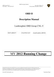
<strong>OBD</strong> <strong>II</strong><br />
Description Manual<br />
Lamborghini <strong>OBD</strong> Group 8NL-V<br />
TEST GROUP -<br />
8NLXV05.0406 L140 Gallardo V10<br />
8NLXV06.5474 L147 Murcielago V12<br />
MY <strong>2008</strong><br />
_____________________________________________________________________________________________________________
<strong>Automobili</strong> Lamborghini s.p.a. <strong>OBD</strong><strong>II</strong> – MY 08 <strong>Intro</strong>duction Page 2<br />
<strong>OBD</strong> Group 8NL-V<br />
Test Group 8NLXV05.0406 – 8NLXV06.5474<br />
<strong>OBD</strong> Description<br />
MODEL YEAR <strong>2008</strong> <strong>OBD</strong> <strong>II</strong><br />
- PART I -<br />
Issue date: 08/nov/2006<br />
Revision date:<br />
<strong>Intro</strong>duction;<br />
This “<strong>LAMBO</strong>RGHINI <strong>OBD</strong> <strong>II</strong> DESCRIPTION MANUAL” is intended to be a description of the<br />
strategies implemented by Lamborghini to fulfill CARB requirements for MY <strong>2008</strong> passenger cars for<br />
the On Board Diagnostic systems (<strong>OBD</strong><strong>II</strong>) installed in the Lamborghini Cars.<br />
Due to the fact that both test group 8NLXV05.0406 (L140 Gallardo V10) and test group<br />
8NLXV06.5474 (L147 Murcielago V12) use the same HW (Lie 2003 ECUs), the same software, the<br />
same <strong>input</strong> / <strong>output</strong> structure (see table below) and, of course, the same <strong>OBD</strong><strong>II</strong> strategies, Lamborghini<br />
Grouped the two test groups in the same <strong>OBD</strong><strong>II</strong> group 8NL-V. In this manual the calibration parameters<br />
which are different between the two cars will be underlined, otherwise the description should be<br />
considered as common to the two applications.<br />
Lamborghini Engine management is composed by two LIE ECUs (one for each bank), that manage<br />
the engine itself, and a third ECU, called GFA, that manage the auxiliary functions. Both LIEs and GFA<br />
manage the Lamborghini <strong>OBD</strong><strong>II</strong> System. They should be considered as component of the same system.<br />
The Lamborghini Gallardo and Murcielago can be optionally equipped with an electronic<br />
transmission; the system is the same for both cars and consists in a manual transmission (no changes on<br />
the clutch and gear-box) coupled with an electronic-hydraulic control for the movements of the clutch<br />
and for the selection and engagement of the gears. The system is managed by a dedicated TCM.<br />
Due to the statement above, the Lamborghini Engine Control Module and Transmission Control<br />
Module have been developed on the management of the following kind of <strong>input</strong> / <strong>output</strong> signal as<br />
described in the tables below.<br />
_____________________________________________________________________________________________________________
<strong>Automobili</strong> Lamborghini s.p.a. <strong>OBD</strong><strong>II</strong> – MY 08 <strong>Intro</strong>duction Page 3<br />
<strong>OBD</strong> Group 8NL-V<br />
Test Group 8NLXV05.0406 – 8NLXV06.5474<br />
<strong>OBD</strong> Description<br />
Issue date: 08/nov/2006<br />
Revision date:<br />
List of all electronic powertrain <strong>input</strong> and <strong>output</strong> signals;<br />
(including those not monitored by the <strong>OBD</strong> <strong>II</strong> system) that identifies which signals are monitored by<br />
the <strong>OBD</strong> <strong>II</strong> system Powertrain ( §1968 .2 (h)(2.7)).<br />
ECM <strong>input</strong>/<strong>output</strong>:<br />
Signal<br />
Description<br />
<strong>OBD</strong> 2<br />
L140<br />
L147 monitoring<br />
Input – Pin 4 of each Lie Water Temperature bank 1<br />
Water Temperature<br />
yes<br />
(pin bank 2 free)<br />
(one for each bank)<br />
Input – Internal to Gfa Barometric Pressure yes<br />
Input – Pin 41 of each Lie Air Temperature bank 2 (pin bank 1 free) Air Temperature (one yes<br />
for each bank)<br />
Input – Pin 6 of each Lie Rear on/off Lambda sensor (One for each bank) yes<br />
Input – Pin 19 of each Lie Front Uego Lambda sensor (Vp+, one for each bank) yes<br />
Input – Pin 22 of each Lie Front Uego Lambda sensor (Vp- / Vs-, one for each bank) yes<br />
Input – Pin 45 of each Lie Front Uego Lambda sensor (Vs+, one for each bank) yes<br />
Input – Pin 34 of each Lie Front Uego Lambda sensor (RComp, one for each bank) yes<br />
Input – Pin 30 of each Lie Catalyst Temperature (one for each bank) yes<br />
Input – Pin 31 Lie bank 2 Oil Temperature yes<br />
Input – Pin 43 Lie bank 1 Oil pressure no<br />
Input – Pin 16 Lie bank 2 Tank pressure yes<br />
Input – Pin 33 of each Lie Manifold Absolute Pressure yes<br />
Input – Pin 15 of each Lie Pedal position – ECU 1 gets the signal from sensor 1, ecu 2 from sensor 2 yes<br />
Input – Pin 12 of each Lie Signal MOT yes<br />
Input – Pin 38 of each Lie Signal CAM inlet (one for each bank) yes<br />
Input – Pin 28 of each Lie / KEY ON<br />
yes<br />
Pin 2 of Gfa<br />
Input – Pin 47 of bank 1 Brake status no<br />
Input – Pin 47 of bank 2 Brake light no<br />
Input – Pin 48 of bank 1 Air conditioning no<br />
Input – Pin B15 Gfa Exhaust Pressure right yes<br />
Input – Pin C6 Gfa Exhaust Pressure left yes<br />
Input – Pin 32 of each Lie Knock signal no<br />
Input – Pin 49 of each Lie Signal CAM outlet (one for each bank) yes<br />
Input – Pin B 1 Gfa Switch Positive Crank Ventilation (PCV) right yes<br />
Input – Pin B 1 Gfa Switch Positive Crank Ventilation (PCV) left yes<br />
Communication CAN – Pin CAN Low main 1 Mbit<br />
yes<br />
7 of each Lie / D14 Gfa<br />
Communication CAN – Pin CAN High main 1 Mbit<br />
yes<br />
8 of each Lie / D3 Gfa<br />
Communication CAN – Pin CAN Low DRIVE BY WIRE 250 Kbit (one for each bank)<br />
yes<br />
9 of each Lie<br />
Communication CAN – Pin CAN High DRIVE BY WIRE 250 Kbit ( one for each bank)<br />
yes<br />
10 of each Lie<br />
Input – Pin 35 of each Lie / Write enable<br />
no<br />
D16 Gfa<br />
Input – Pin 36 of each Lie ECU selection yes<br />
Output – Pin 65 Lie bank 2 Canister Vent Valve yes<br />
Output – Pin 63 of each Lie Purge Valve (one for each bank) yes<br />
Output – Pin 62 of each Lie Intake variable timing valves (one for each bank) yes<br />
Output – Pin 64 of each Lie Exhaust variable timing valves (one for each bank) yes<br />
Output – Pin 65 Lie bank 1 Electro valve Air pump yes<br />
Output – Pin 54 Lie bank 2 Electro valve Exhaust noise control system (ENCS) yes<br />
Output – Pin 55 Lie bank 2 Electro valve Variable Intake System (VIS) yes<br />
_____________________________________________________________________________________________________________
<strong>Automobili</strong> Lamborghini s.p.a. <strong>OBD</strong><strong>II</strong> – MY 08 <strong>Intro</strong>duction Page 4<br />
<strong>OBD</strong> Group 8NL-V<br />
Test Group 8NLXV05.0406 – 8NLXV06.5474<br />
<strong>OBD</strong> Description<br />
Issue date: 08/nov/2006<br />
Revision date:<br />
Output – Pin 58 Lie bank 1 Relay Air Pump Yes<br />
(Functional)<br />
Output – Pin 60 of each Lie Front UEGO sensor Heater (one for each bank) yes<br />
Output – Pin 59 of each Lie Injectors power supply relay (one for each bank) no<br />
Output – Pin 58 Lie bank 2 Coil power supply relay (one for each bank) no<br />
Output – Pin from 68 to 73 Single coils cylinders from 1 to 10 (pin 73 of Single coils cylinders yes<br />
of each Lie<br />
Output – Pin from 74 to 79<br />
of each Lie<br />
Communication Serial – Pin<br />
21 of each Lie / D15 of Gfa<br />
Input - Pin 2 of each Lie /<br />
Pin 1 of Gfa<br />
each bank free)<br />
Injector cylinders from 1 to 10 (pin 79 of each<br />
bank free)<br />
LINE K<br />
Battery voltage<br />
from 1 to 12<br />
Injector cylinders from<br />
1 to 12<br />
yes<br />
yes<br />
yes<br />
TCM <strong>input</strong>/<strong>output</strong>:<br />
Signal Description <strong>OBD</strong> 2<br />
monitoring<br />
Communication CAN “L” CAN Low<br />
yes<br />
pin 7<br />
Communication CAN “H” CAN High<br />
yes<br />
pin 19<br />
Communication Serial – Pin<br />
49<br />
K-line<br />
yes<br />
Input pin 78 Switch door no<br />
Input pin 46, 34, 35, 47 Clutch position sensor yes<br />
Input pin 38, 50 Clutch speed yes<br />
Can Driveline speed yes<br />
Output pin 32 Electro valve 1 yes<br />
Output pin 44 Electro valve 2 yes<br />
Output pin 29 Electro valve 3 yes<br />
Output pin 3 Electro valve 4 yes<br />
Output pin 30 Electro valve 5 yes<br />
Output pin 43 Electro valve 6 yes<br />
Input pin 48 Engine speed yes<br />
Input pin 39 Gear select sensor yes<br />
Input pin 51 Gear shift sensor yes<br />
Input pin 40 Hydraulic pressure sensor yes<br />
Input pin 77 Switch “auto” no<br />
Input – from Pin 42 Lie Signal “ Low adherence, Sport, Normal ”<br />
no<br />
bank 2<br />
Input pin 27 TCM power relay yes<br />
The row in green highlated rapresents the the description add in the MY08 documentation<br />
_____________________________________________________________________________________________________________


