AFMETCAL Newsletter - Wright-Patterson Air Force Base
AFMETCAL Newsletter - Wright-Patterson Air Force Base
AFMETCAL Newsletter - Wright-Patterson Air Force Base

Create successful ePaper yourself
Turn your PDF publications into a flip-book with our unique Google optimized e-Paper software.
DISTRIBUTION A. Approved for public release; distribution unlimited. (WP Public Affairs Case Number 88ABW-2011-XXXX).<br />
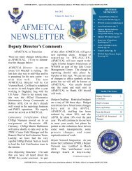
Director’s Comments<br />
The AF conducts <strong>Air</strong>craft Mishap<br />
investigations to determine the cause<br />
of accidents for the purpose of<br />
preventing future mishaps.<br />
I was involved in investigating an<br />
F-16 crash where initially there was<br />
very little evidence. Oddly enough, a<br />
photo was taken in front of the jet of<br />
a re-enlistment a couple hours prior to<br />
that jet taking off for its final mission<br />
(pilot survived and flew less than a<br />
week later). The picture was<br />
provided to show the nose wheel tire<br />
was properly installed. What a trained<br />
investigator detected, using his<br />
‘calibrated’ eyes, was the tire<br />
appeared underinflated. The team of<br />
experts followed that lead and in fact<br />
determined an underinflated nose tire<br />
was one of the causes of the crash.<br />
Through the investigation process,<br />
the tire inflation kit, and subsequently<br />
the PMEL who calibrated it, were<br />
vindicated. I frequently tell people<br />
that calibration and metrology, aka<br />
PMEL, are behind the scenes support<br />
activities that only gain attention<br />
when something goes wrong.<br />
July 2011<br />
Volume 31, Issue No. 4<br />
<strong>AFMETCAL</strong><br />
NEWSLETTER<br />
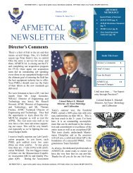
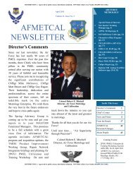
Colonel Robert E. Mitchell<br />
Director, <strong>Air</strong> <strong>Force</strong> Metrology<br />
and Calibration<br />
just never know when something is<br />
going to go wrong.<br />
Thanks for all that you do for our <strong>Air</strong><br />
<strong>Force</strong>. Have a safe and enjoyable<br />
summer!<br />
Until next time…. “<strong>Air</strong> Superiority<br />
through Precision”!<br />
Colonel Robert E. Mitchell<br />
Director, <strong>Air</strong> <strong>Force</strong> Metrology and<br />
Calibration<br />
AIR FORCE<br />
METROLOGY<br />
Special Points of Interest:<br />
• Authorized Deviation/<br />
Modification of TOs (pg. 4)<br />
• Maj Gen Fedder Visits<br />
Ramstein PMEL (pg. 5)<br />
• PMEL U&TW (pg. 6)<br />
• White Space Initiative (pg. 11)<br />
• USAF Material Deficiency<br />
Reporting (pg. 12)<br />
• Deleted K-100 Report? (pg. 14)<br />
• Misawa PMEL Personnel<br />
Survive Earthquake (pg. 15)<br />
• How Did You Celebrate World<br />
Metrology Day? (pg. 18)<br />
• Kunsan PMEL Completes<br />
Successful <strong>AFMETCAL</strong><br />
Assessment (pg. 19)<br />
• EF3946-FTS Liquid Flow<br />
Transfer Standard Upgrade<br />
Details (pg. )<br />
• Understanding Third Order<br />
Intermodulation (pg. )<br />
• ADC 2500 <strong>Air</strong> Data Calibrator<br />
Data Storage Problem (pg. )<br />
• Calculating Relative TRFL of<br />
MMR (pg. )<br />
Inside This Issue:<br />
Director’s Comments 1<br />
Chief’s Corner 3<br />
News and Notes 4<br />
From the Bench<br />
•<br />
Coming Events:<br />
We need to continue to produce a<br />
100% quality product because you<br />
DISTRIBUTION A. Approved for public release; distribution unlimited. (WP Public Affairs Case Number 88ABW-2011-XXXX).
Page 2<br />
<strong>AFMETCAL</strong> NEWSLETTER<br />
July 2011<br />
Volume 31, Issue No. 4<br />
The views and<br />
opinions expressed<br />
herein, unless<br />
otherwise specifically<br />
indicated, are those of<br />
the individual author.<br />
They do not purport to<br />
express the views of<br />
the U.S. Government,<br />
the Department of<br />
Defense, Department<br />
of the <strong>Air</strong> <strong>Force</strong> or<br />
HQ AFMC.<br />
Disclosure & Editorial Policy<br />
Disclosure: The <strong>Air</strong> <strong>Force</strong> Metrology and<br />
Calibration (<strong>AFMETCAL</strong>) Program <strong>Newsletter</strong><br />
is published on a quarterly basis (Jan,<br />
Apr, Jul, Oct) by the <strong>AFMETCAL</strong> Division<br />
(WR-ALC/ENH), Plans & Analysis Section<br />
(<strong>AFMETCAL</strong>/ENHRX), 813 Irving-Wick<br />
Drive W, Heath, Ohio 43056-1199.<br />
The views and opinions expressed herein,<br />
unless otherwise specifically indicated, are<br />
those of the individual author. They do not<br />
purport to express the views of the U.S.<br />
Government, the Department of Defense,<br />
Department of the <strong>Air</strong> <strong>Force</strong> or HQ AFMC.<br />
Information contained in the <strong>AFMETCAL</strong><br />
<strong>Newsletter</strong> is for informational purposes and<br />
is not directive in nature. Photographs are<br />
the property of the United States <strong>Air</strong> <strong>Force</strong><br />
unless otherwise stated.<br />
The appearance of hyperlinks does not constitute<br />
endorsement by the U.S. <strong>Air</strong> <strong>Force</strong> of<br />
the respective web site or the information,<br />
products or services contained therein. The<br />
U.S. <strong>Air</strong> <strong>Force</strong> does not exercise any editorial<br />
control over the information found at those<br />
locations.<br />
Editorial Policy Statement: The AFMET-<br />
CAL Quarterly <strong>Newsletter</strong> is the AFMET-<br />
CAL Director’s forum to share insights into<br />
policy and emerging trends, personnel news,<br />
technical and other information of interest to<br />
the <strong>Air</strong> <strong>Force</strong> metrology community at large.<br />
<strong>Newsletter</strong> articles cover many topics: technical<br />
issues; clarifications of policies/<br />
procedures; process improvements; and items<br />
of general interest about <strong>Air</strong> <strong>Force</strong> metrology<br />
community members.<br />
Submissions: We encourage readers to submit<br />
articles for the following categories:<br />
From the Bench (technical), About People<br />
(field personnel news), News & Notes<br />
(general information). Submissions should<br />
be in Microsoft Word, Times New Roman 12<br />
font, accompanied whenever possible by<br />
digital photos in JPEG format. Native photo<br />
file sizes less than 2MB per image are preferred.<br />
Photos must be accompanied with<br />
caption information which fully identifies all<br />
individuals depicted, including rank, title<br />
or office, and event. Note that all text and<br />
photo submissions are subject to editing<br />
for content, cropping and/or size. All submissions<br />
that are technical in nature are<br />
reviewed by the <strong>AFMETCAL</strong> Engineering<br />
Branch (<strong>AFMETCAL</strong>/ENHE) for accuracy<br />
and appropriateness. Publication of any<br />
submission, regardless of subject matter,<br />
will be approved by the <strong>AFMETCAL</strong> Division<br />
and submission does not guarantee<br />
publication. All submissions are reviewed<br />
for compliance with Privacy Act, FDO,<br />
STINFO, OPSEC and other information<br />
security requirements as applicable.<br />
How to Make a Submission: The AF-<br />
METCAL <strong>Newsletter</strong> editor transmits<br />
quarterly calls for inputs through the<br />
PMEL MAJCOM Functional Managers<br />
and other significant metrology program<br />
POCs to the respective PMEL managers<br />
and/or program functional offices. Normal<br />
submissions are in response to these data<br />
calls. Authors should submit their article<br />
inputs via e-mail through their respective<br />
chain of command to the <strong>AFMETCAL</strong><br />
<strong>Newsletter</strong> editor. Authors may submit<br />
inputs out of cycle, but should use the<br />
same channels for those submissions.<br />
Deadline for submissions is the 15th of the<br />
month prior to the scheduled quarterly<br />
newsletter publication. Do not submit<br />
copyrighted material.<br />
Director, <strong>Air</strong> <strong>Force</strong> Metrology &<br />
Calibration<br />
Colonel Robert E. Mitchell, USAF<br />
Editor:<br />
Bob Nappier<br />
Assistant Editor:<br />
Lee Wood
Page 3<br />
<strong>AFMETCAL</strong> NEWSLETTER<br />
July 2011<br />
Volume 31, Issue No. 4<br />
Chief’s Corner<br />
Fellow Maintainers,<br />
I must have missed the memo last<br />
year, but 2011 seems like the year<br />
of change and transformation.<br />
Those of you I have served with<br />
throughout the years know how<br />
much I embrace, encourage and<br />
facilitate change…no really, I do.<br />
However, after taking some time<br />
to reflect, these changes will<br />
improve our career field and the<br />
entire AF.<br />
The first major change will be the<br />
<strong>AFMETCAL</strong> Assessment process.<br />
In May, MSgt Sean Jenigen<br />
and I attended the AF Inspection<br />
Efficiencies Conference, hosted<br />
by the Inspector General. While<br />
there, we had the opportunity to<br />
help map the future of the entire<br />
AF Inspection System. MSgt<br />
Jenigen’s article details our way<br />
forward on several issues and the<br />
ongoing initiatives, but this is still<br />
a fluid process. At this point, two<br />
changes appear imminent, our<br />
assessment schedule and how we<br />
assess the six critical areas. The<br />
criteria for certification remains<br />
the same, so what passed prior to<br />
October will pass after October.<br />
The end goal of this process is<br />
provide the unit more time to train<br />
and perform their mission by<br />
establishing an AF-wide battle<br />
rhythm for inspections and reducing<br />
the on-site footprint for each<br />
inspection.<br />
We are also facing a Tier 3 Manpower<br />
Study. This is the most<br />
intense type of study and can take<br />
up to a year to complete. In the<br />
first phase, all processes are evaluated<br />
to the task level, determining<br />
the core workload and time<br />
required to accomplish each task.<br />
By now, all non-contract PMELs<br />
should have completed the Process<br />
Oriented Description (POD) and<br />
submitted their data to the 2 MRS.<br />
I understand this was a painful part<br />
of the process and thank everyone<br />
for their support. I want to emphasize<br />
the POD data is not the sole<br />
source determining the requirements<br />
for your PMEL, it is merely<br />
the first step. The second phase<br />
determines the steps required to<br />
accomplish the task. This will be<br />
the foundation utilized to develop<br />
the measurement tools/methodologies.<br />
Once this step is complete<br />
and the 2 MRS determines the<br />
measurement method, they will<br />
capture the associated man-hours<br />
leading to the manpower equation<br />
development.<br />
Another change I have noticed<br />
over the past year is the use of<br />
social media sites to broadcast the<br />
pride everyone feels when they do<br />
well on an assessment. Some are<br />
so proud, they post daily updates<br />
and the final assessment results. I<br />
appreciate the hard work that goes<br />
into an <strong>AFMETCAL</strong> assessment<br />
and the desire to share the good<br />
news, but I encourage everyone to<br />
think twice before posting your<br />
PMEL’s final results and daily<br />
Measurement Capability Assessment<br />
(MCA) updates. When the<br />
AF opened these networking sites,<br />
it came with a responsibility to<br />
Chief Master Sergeant<br />
Craig “Woody” Niemann<br />
Chief, Laboratory Certification<br />
Branch<br />
educate everyone to protect information<br />
that gives insight into our<br />
operational capabilities. The<br />
MCA, along with the rest of the<br />
certification criteria, is an important<br />
indicator of the PMEL’s capability.<br />
Take pride in your hard<br />
work, but consider what you are<br />
sharing before posting it to the<br />
internet.<br />
I would encourage everyone to<br />
read the article written by TSgt<br />
Blair. This should not be a change<br />
for anyone; following the TO<br />
should always be the first priority.<br />
I know we have smart people in<br />
this career field and I encourage<br />
everyone to change the TO<br />
(Continued on page 4)
Page 4<br />
<strong>AFMETCAL</strong> NEWSLETTER<br />
July 2011<br />
Volume 31, Issue No. 4<br />
Chief’s Corner (continued)<br />
(Continued from page 3)<br />
methodology by submitting an AFTO 22, if it improves the process for the AF. The assessment team takes<br />
each situation into consideration, especially, if a PMEL has unique standards. However, if you are coming up<br />
with your own methodology for making a measurement, I would encourage you to be very cautious. The calibrations<br />
we perform are complex and many times our engineers account for uncertainties that might not be obvious.<br />
If you have specific questions on substitution and uncertainty, follow the guidance in TO 00-20-14.<br />
Additionally, PMEL managers need to be aware of TO/AFI guidance and are not exempt from it. While not a<br />
trend, the team has encountered situations where a manager did not accomplish a requirement within the<br />
directed time-period (i.e. a Management Review or Internal Audit) and merely documented the discrepancy on<br />
a Memo for Record (MFR). Identification is the first step; however, documenting lack of compliance with an<br />
AF directive on a MFR does not absolve the PMEL of responsibility. If a PMEL does not meet requirements<br />
and has not corrected the issue, you can expect the assessment team to take note. Again, this is not a significant<br />
trend, but it has come up enough to be mentioned.<br />
In closing, since assuming the 2P0X1 Career Field Manager duties, I have not been able to attend as many<br />
assessments as I would like. Nevertheless, I am continually amazed at the things our diverse PMEL team<br />
(contractor, blue-suit, civil service) accomplishes on a daily basis. Because of the talent at every level of our<br />
career field, I have no doubt we will continue to work through these changes and come out with a much healthier<br />
team. Thanks to everyone for all you do. As always, if you have any questions or concerns about the<br />
<strong>AFMETCAL</strong> Assessment team, feel free to contact me.<br />
C. “Woody” Niemann, CMSgt, USAF<br />
Chief, Laboratory Certification Branch<br />
News and Notes<br />
Authorized Deviation/Modification of Technical Orders<br />
Throughout my career I’ve always heard other PMEL technicians say we are authorized to modify or deviate<br />
from calibration procedures as long as we can “prove” our methodology. However, TOs 00-20-14 and 00-5-1<br />
do not authorize technicians to deviate from, or to modify calibration procedures as they see fit. Many times<br />
technicians feel they can justify their deviations because they think their methodology meets the intent of the<br />
calibration TO and “they know a better way to do it”. As maintainers, we are required to follow calibration<br />
TOs to the letter. The only time we are allowed to modify methods is when a substitute standard is used as<br />
outlined in TO 00-20-14. If there is a faster, cheaper, or safer way of performing the calibration, then submit<br />
an AFTO 22 on the calibration procedure. Once the calibration procedure has been changed, then the new<br />
methods may be employed. Remember that we are calibration technicians, not engineers and we must follow<br />
calibration TOs to the letter.<br />
(Continued on page 5)
Page 5<br />
<strong>AFMETCAL</strong> NEWSLETTER<br />
July 2011<br />
Volume 31, Issue No. 4<br />
News and Notes (continued)<br />
Authorized Deviation/Modification of Technical Orders (cont.)<br />
(Continued from page 4)<br />
Bottom line, if you are using what the TO calls for, you aren’t authorized to deviate from that TO. If you know<br />
a better, cheaper, faster or safer way, submit an AFTO Form 22 and then follow that up with an IDEA program<br />
submittal.<br />
Christopher Blair, TSgt<br />
Physical Dimensional Work Area Supervisor<br />
Nellis AFB, NV<br />
Maj Gen Fedder Visits Ramstein AB PMEL<br />
Major General Judith A. Fedder is Director of<br />
Logistics, Deputy Chief of Staff for Logistics,<br />
Installations and Mission Support, Headquarters U.S.<br />
<strong>Air</strong> <strong>Force</strong>, Washington, D.C. She is responsible for<br />
organizing, training, and equipping more than 180,000<br />
technicians and managers maintaining the <strong>Air</strong> <strong>Force</strong><br />
global engagement aerospace weapons system<br />
inventory. Major General Fedder recently visited<br />
Ramstein <strong>Air</strong> <strong>Base</strong>, Germany to get a better<br />
understanding of the base's logistical operations. She<br />
spent her day visiting many different logistics-related<br />
sections in order to gain a first-hand perspective.<br />
Pictured above: Major General Judith Fedder addresses<br />
attendees as the guest speaker at the 86 MXG Maintenance<br />
Professional of the Year Banquet during her recent visit to<br />
Ramstein AB Germany.<br />
One of the stops on Major General Fedder’s tour was<br />
to the 86th Maintenance Squadron TMDE Flight.<br />
Here she saw an initiative of hers, E-Tools, in full<br />
effect. The laboratory technical order operation is<br />
100% paperless through the procurement and<br />
implementation of E-Tools. She then took a tour of<br />
the facility with A1C Vega demonstrating the<br />
accuracies of our calibrations by weighing her official<br />
signature. Major General Fedder culminated her visit<br />
to Ramstein AB as the guest speaker at the 86 MXG<br />
Maintenance Professional of the Year banquet.<br />
MSgt Jacob Peeterse<br />
Ramstein PMEL
Page 6<br />
<strong>AFMETCAL</strong> NEWSLETTER<br />
July 2011<br />
Volume 31, Issue No. 4<br />
News and Notes (continued)<br />
PMEL Utilization and Training Workshop (U&TW)<br />
Editor’s Note: The following three articles are three different perspectives offered by attendees to the<br />
PMEL U&TW.<br />
From April 18-22, 2011, the PMEL Utilization and Training Workshop (U&TW) convened at Keesler AFB,<br />
Biloxi, MS. The U&TW is used to determine education and training requirements for us, PMEL. This is<br />
accomplished by bringing in experts from the career field and using that knowledge to establish the most<br />
effective mix of formal and on-the-job training for each skill level. The U&TW happens every three years, but<br />
is something that not everyone gets to experience or even knows about. In my 13 years in PMEL, I didn't even<br />
know a U&TW happened until I took an instructor position; because of this, I thought it would be very beneficial<br />
to hear the perspective of the two junior NCOs in attendance of the 2011 U&TW, SSgt Michael Ocampo<br />
and SSgt Jason DeGrasse.<br />
The opportunity is out there to directly impact the career field and have your voice heard. Build your technical<br />
expertise and you might find yourself sitting in a room with way too many stripes to count and the opportunity<br />
to make a change to PMELs everywhere!<br />
TSgt Nathan D. Cyr<br />
Instructor Supervisor, Supplemental Courses<br />
Keesler AFB, MS<br />
A Junior Enlisted Member’s View<br />
(The writer of this article is currently a section supervisor at Charleston AFB, SC and K1/K8 SME of <strong>Air</strong><br />
Mobility Command. He attended the 5-day long U&TW at Keesler AFB, MS, per his Functional Manager's<br />
request. Members wishing to participate in this capacity should seek assistance from his/her Flight Chief.)<br />
"…low man on the totem pole". As the Precision Measurement Equipment Laboratory Utilization and<br />
Training Workshop began the monumental task of re-defining the future of the career field, all attending<br />
members were asked to introduce themselves. They were to face the group and explain who they are in the<br />
world of PMEL. "Chief This" and "Functional Manager That" were declared around the room, and then all<br />
eyes were on me. "Good morning. I am SSgt Michael Ocampo, and apparently... I am the low man on the<br />
totem pole."<br />
For those readers who are unaware of what the U&TW actually is, let me enlighten you. Every few years, the<br />
PMEL functional managers of each command, the CDC writers, and the basic/supplemental course instructors<br />
convene to do a utilization review of the career field. In short, the task at hand is to ensure that, from the<br />
Electronic Principles course all the way up to the working laboratories, PMEL technicians have the resources<br />
to complete the mission with maximum efficiency. With all of these program managers present to make<br />
decisions affecting the labs, shouldn't those actively working in the field have a voice? This is where I come<br />
into the picture. I was invited to provide the perspective of the reporting official gaining a pipeline student, to<br />
give the perspective of the trainer or section supervisor, and to give the perspective of the subject-matter<br />
expert. Many issues are presented to the voting members of the conference. Issues such as what equipment we<br />
should teach, and to what proficiency level are hot topics. Other issues include the currency of the CDC<br />
(Continued on page 7)
Page 7<br />
<strong>AFMETCAL</strong> NEWSLETTER<br />
July 2011<br />
Volume 31, Issue No. 4<br />
News and Notes (continued)<br />
PMEL Utilization and Training Workshop (U&TW) (continued)<br />
(Continued from page 6)<br />
material or the modernization of equipment in the field (subsequently affecting the whole CFETP). It is all<br />
pretty heavy stuff if you ask a Staff Sergeant...which is precisely what they did! The subject-matter experts<br />
were invited across every rank demographic beginning with E-5, to ensure a fresh perspective while<br />
maintaining an experienced, critical eye on the field.<br />
Just as the topics varied, so did the level of discussion on each topic. It was exhilarating to witness universal<br />
concurrence at one moment, then suddenly "spirited debate" due to non-concurrence at the very next! By far<br />
though, the most satisfying moments came when the subject I was brought in to analyze was broadcast on the<br />
big screen. It would be time to showcase my knowledge. It would be time to voice what really happens in the<br />
lab, on my peers' behalf. This is where the blood pressure would rise, because win, lose, or draw... it would be<br />
time to earn my keep! At times, I was able to explain my position and garner concurrence from the members.<br />
Other times, I would be enlightened by other SMEs in a different position within their MAJCOM. Maybe only<br />
once in your career (for most enlisted members), will you find yourself with the attention of every Chief and<br />
MFM in PMEL while they inquire, "What do you think?" Certainly AF members are asked this rhetorically<br />
numerous times during their careers, but it is truly empowering to have the voting members ask it with honest<br />
intent, consider your remarks, and nod their heads in agreement. Just like that, the career field (at least until the<br />
next U&TW) is changed.<br />
In the end, I acquired a completely different level of respect for each and every functional manager. I equate<br />
what I witnessed to a Senate or Congressional meeting, complete with hard-fought issues and voting members<br />
arranged at a head table. Putting a face to the names and seeing the responsibility they carried is definitely a<br />
humbling experience. These people were molding the future of the career field right before my eyes. It was<br />
an honor lending a hand in any way I could. Of course on my last day, I tried to thank everyone present for the<br />
opportunity to participate. I must admit that I felt a sense of pride when the decision-makers were seeking out<br />
little-old-me, to give thanks for my input. Not too shabby for "the low man on the totem pole", if you ask<br />
me... and I hope you do.<br />
SSgt Michael Ocampo<br />
AMC Representative, Subject Matter Expert<br />
Charleston AFB, SC<br />
Notes From The Note Taker<br />
Have you ever walked into a room and felt like you didn’t belong? That’s how I felt walking in the auditorium<br />
at Wolfe Hall on April 18 th , 2011. You see, I walked into a room with every PMEL MFM sitting at a table,<br />
our PMEL CFM, Chief Niemann, glaring me down, and, because not enough rank was already in the room,<br />
another Chief from AETC, our Training Pipeline Manager. That’s a total of 73 stripes between the ten voting<br />
members. After the introductions, the workshop quickly got underway. The first day and a half were briefings,<br />
most of which were boring. According to MSgt Earp, the AFGSC PMEL MFM, those briefings were<br />
boring because I lacked that strategic level of thinking and scope that all SNCOs must have. In other words, he<br />
called me dumb. After those extremely informative briefings to those with the scope and boring briefings to<br />
(Continued on page 8)
Page 8<br />
<strong>AFMETCAL</strong> NEWSLETTER<br />
July 2011<br />
Volume 31, Issue No. 4<br />
News and Notes (continued)<br />
PMEL Utilization and Training Workshop (U&TW) (continued)<br />
(Continued from page 7)<br />
those without it, we got down to what everyone was brought to Keesler for…the review. The review consisted<br />
of going line by line through the CFETP, CDCs, and all four courses (Apprentice, Phys-D, TACAN, and Adv.<br />
Cal) taught at Keesler AFB. My job during the workshop was two-fold: I was the note taker for the minutes<br />
and the Phys – D course representative. For those of you who know me, I had to actually stay quiet for long<br />
periods of time. Yes, I know it’s unbelievable and it took an enormous amount of restraint. There were<br />
several experts from the career field here as well; some were a little more boisterous than others, but all<br />
sections and MAJCOMs had adequate representation. Many changes were made to the CFETP because<br />
technicians and supervisors in the career field felt a need. Those long and extremely boring surveys everyone<br />
blazes through without really understanding what and why we’re taking them were actually being used. If the<br />
data showed an increase in any particular area (use, align, troubleshoot, calibration of any piece of TMDE) the<br />
voting members took a serious look at how they should address it. They used the experts in attendance<br />
from the <strong>Air</strong> University and Occupational Analysis on how to properly make changes if the SMEs and data<br />
indicated a change was needed. No change was made without serious consideration to the impact it would<br />
have on the career field and the needs of our <strong>Air</strong> <strong>Force</strong>. Just imagine, Chief Leary, ACC PMEL MFM, after<br />
giving you his now infamous stare, asking for your input on a particular subject. Your answer will directly<br />
affect whether or not a piece of TMDE is now a core task, whether or not the apprentice course will still teach<br />
the 2246, whether or not the PHYS-D course will start teaching TTU-205s, or whether or not troubleshooting<br />
will remain a part of the TACAN course. In my opinion, it was awesome. I loved it. If you ever get the<br />
opportunity to attend a U&TW, I’d highly recommend it, even if you are just the note taker.<br />
SSgt Jason DeGrasse<br />
K6 Supplemental Course Instructor, Subject Matter Expert<br />
Keesler AFB, MS<br />
(Contributors of these articles attended the 5-day long U&TW at Keesler AFB, MS. Members wishing to<br />
participate in this key capacity should seek assistance from his/her Flight Chief.)<br />
Pictured at left:<br />
SSgt Jason DeGrasse<br />
(left) and<br />
SSgt Michael<br />
Ocampo (right)<br />
working diligently at<br />
finding the information<br />
that would<br />
change PMEL<br />
forever (at least the<br />
next three years).<br />
Photo by:<br />
TSgt Nathan Cyr<br />
(Continued on page 9)
Page 9<br />
<strong>AFMETCAL</strong> NEWSLETTER<br />
July 2011<br />
Volume 31, Issue No. 4<br />
News and Notes (continued)<br />
PMEL Utilization and Training Workshop (U&TW) (continued)<br />
(Continued from page 8)<br />
Editor’s note: The pictures below and on the next page were provided by the Keesler Schoolhouse and<br />
show the U&TW meeting in progress with some of the attendees from the PMEL community.<br />
(Continued on page 10)
Page 10<br />
<strong>AFMETCAL</strong> NEWSLETTER<br />
July 2011<br />
Volume 31, Issue No. 4<br />
News and Notes (continued)<br />
PMEL Utilization and Training Workshop (U&TW) (continued)<br />
(Continued from page 9)
Page 11<br />
<strong>AFMETCAL</strong> NEWSLETTER<br />
July 2011<br />
Volume 31, Issue No. 4<br />
News and Notes (continued)<br />
The White Space Initiative<br />
White Space – you’re probably asking yourself “what is White Space”. Good question, because there’s not<br />
enough of it. White Space is the space on a calendar in-between inspections. You know what it’s like – this<br />
week it’s LCAP, next week is ESOCAMP, then the ORI and then <strong>AFMETCAL</strong> rolls in, etc. It’s just a<br />
constant string of inspections. Here’s a fun fact, over a 5 year period, the average wing had 97+ inspections<br />
totaling over 350 inspection days. The <strong>Air</strong> <strong>Force</strong> Chief of Staff (CSAF) heard the cry and put forth his vision:<br />
Reduce, Synchronize, Integrate.<br />
REDUCE: Reduce the number of AF inspections and reduce what is inspected on-site. The goal is to shrink<br />
the overall inspection footprint for a wing; ideally all inspections will be 5 duty days or less.<br />
SYNCHRONIZE: Synchronize all remaining inspections with the Secretary of the AF, Inspector General<br />
(SAF/IG) into a Combined Unit Inspection (CUI). All inspections will be on a 2 or 4 year cycle. So, one<br />
week every 2 years, your base will have its CUI, with all inspections taking place concurrently (LCAP,<br />
<strong>AFMETCAL</strong>, etc). The assessment team expects to be fully synchronized with SAF/IG by Oct 2013. To meet<br />
this goal, the assessments at Osan, Kunsan and Al Udeid will now be on a 2 year cycle.<br />
INTEGRATE: Integrate under the SAF/IG umbrella. The IG is, by US law, the only inspection authority in<br />
the AF, so all AF inspections will eventually have to integrate at some level with the IG. The assessment<br />
team’s goal is full integration by Oct 2013; however, we still have a few issues to work out.<br />
CHANGE. What does this mean for PMEL and <strong>AFMETCAL</strong>? The assessment team has taken a hard look at<br />
how we perform our onsite assessments to see what we can modify to comply with CSAF’s vision. We<br />
determined the 6 critical areas currently looked at are still the right areas to assess. However, by collecting a<br />
little more pre-assessment data upfront, we can determine a grade on 3 of the 6 areas prior to setting foot in the<br />
PMEL. The areas we can grade ahead of time are the Management System (MS), Proficiency Testing/<br />
Measurement Assurance Program (PT/MAP) and Environment. The Quality Program (QP), Measurement<br />
Capability Assessment (MCA) and Facility will still be graded on site.<br />
After working closely with the Headquarters AF Logistics Compliance Assessment Program (LCAP) office,<br />
we realized there was some overlap between <strong>AFMETCAL</strong> and LCAP assessments in the PMEL management<br />
functions. <strong>AFMETCAL</strong> reviewed these areas, but didn’t rate them. The LCAP inspected these areas for<br />
compliance and a grade. To reduce the overlap, <strong>AFMETCAL</strong> will no longer look at those areas the LCAP<br />
inspects (i.e. supply, scheduling, shipping, etc).<br />
MORE CHANGE. The assessment team will no longer sit down for formal interviews on the QP and MS.<br />
Instead of the interview, the team will provide written feedback on these programs, allowing the team to get<br />
“out of the weeds” and give a macro look. The team will still be open to discussion on issues or questions<br />
management or QA have on their programs, but no formal session will be planned.<br />
By implementing these changes, coupled with a few tweaks to how we conduct the MCA, we can eliminate at<br />
least one assessment day. This allows the assessment team to meet the CSAF challenge by bringing the<br />
average time in the laboratory to within the 5 day vision.<br />
(Continued on page 12)
Page 12<br />
<strong>AFMETCAL</strong> NEWSLETTER<br />
July 2011<br />
Volume 31, Issue No. 4<br />
News and Notes (continued)<br />
(Continued from page 11)<br />
The White Space Initiative (continued)<br />
Our plan is to implement these changes starting 1 October 2011. Please keep in mind there is still much<br />
changing in the AF. We will continue to adjust the <strong>AFMETCAL</strong> assessment program as needed to comply<br />
with CSAF and SAF/IG directives, while maintaining a stringent technical certification assessment. Please<br />
direct any questions regarding <strong>AFMETCAL</strong> and White Space to your MAJCOM/MFM. They will consolidate<br />
and forward to the team.<br />
Sean P. Jenigen, MSgt, USAF<br />
USAF Metrology Laboratory Lead Evaluator<br />
USAF Material Deficiency Reporting<br />
Annually, <strong>AFMETCAL</strong> publishes a Logistics Analysis Report. The report is prepared and provided to<br />
<strong>AFMETCAL</strong> program personnel with performance data for use in determining equipment acquisition requirements.<br />
One part of the Logistics Analysis Report is Material Deficiency Reporting including Warranty Repair Data on<br />
<strong>AFMETCAL</strong>-procured assets. In the past, Equipment Failure Information Report (EFIR) was a contractual<br />
requirement from the manufacturer. In FY08, the <strong>Air</strong> <strong>Force</strong> implemented the Joint Deficiency Reporting<br />
System (JDRS). JDRS is the official <strong>Air</strong> <strong>Force</strong> Deficiency Reporting tracking system and repository.<br />
<strong>Air</strong> <strong>Force</strong> Material Deficiency Reporting is mandated per TO 00-35D-54 which includes Warranty Repair<br />
Items. Paragraph 1.6.2.1 states Product Quality Deficiency Reports (PQDRs) are reports of deficiency (on<br />
hardware or software) resulting from an initial failure, defect, or nonconforming condition discovered on a<br />
new, newly-repaired, or overhauled product typically when that product is placed in service. PQDRs include<br />
failures that result after the item was placed in service that are suspected as latent defects or quality escapes<br />
resulting from poor workmanship, nonconformance to applicable specifications, drawings, standards,<br />
processes or other technical requirements. PQDRs also include the reporting of failures that occur on<br />
contractually-prescribed warranted items within the warranty period.<br />
Typically an exhibit is not required per TO 00-35D-54, paragraph 4.6.5 which states:<br />
4.6.5 Category II deficiencies on warranted items other than safety-related and new/newly-reworked<br />
material shall typically be processed according to the individual item warranty plan. While the information<br />
is captured, and may be closed, this type of information can be used for trend analysis. For warranted<br />
items indicate the exhibit is not available. Exhibits will be sent back to the manufacturer.<br />
When completing the Material Deficiency Report in JDRS for <strong>AFMETCAL</strong>-procured items, include the<br />
(Continued on page 13)
Page 13<br />
<strong>AFMETCAL</strong> NEWSLETTER<br />
July 2011<br />
Volume 31, Issue No. 4<br />
News and Notes (continued)<br />
(Continued from page 12)<br />
USAF Material Deficiency Reporting (continued)<br />
contract number which is published in the Equipment Support Plan. By having the contract number, it will be<br />
easy to query the JDRS database rather than query each National Stock Number (NSN) for all the items.<br />
There have only been 14 Material Deficiency Reports entered by the PMELs since 2008. This information<br />
will assist <strong>AFMETCAL</strong> in identifying Bad Actors and possible future equipment acquisitions.<br />
JDRS is a Navy-managed system and website is https://jdrs.mil.<br />
You can access the website via Common Access Card (CAC) or register with a Username and Password. You<br />
can also initiate a Deficiency Report without logging onto the site by selecting Toolkit on the Menu Bar and<br />
following the instructions. Again, please try to include the <strong>AFMETCAL</strong> contract number. It makes it easier to<br />
(Continued on page 14)
Page 14<br />
<strong>AFMETCAL</strong> NEWSLETTER<br />
July 2011<br />
Volume 31, Issue No. 4<br />
News and Notes (continued)<br />
(Continued from page 13)<br />
query the database.<br />
USAF Material Deficiency Reporting (continued)<br />
The requirement to perform product quality deficiency reporting and resolution is mandated by public law and<br />
complementary USAF and DOD guidance.<br />
Tony Oiler<br />
Plans & Analysis Section<br />
<strong>AFMETCAL</strong>/ENHRX<br />
Did you know about the PAMS Deleted K-100 report?<br />
It’s something not often spoken about and it<br />
seems many Schedulers and Lab Managers aren’t<br />
aware of it. It can be found under REPORTS,<br />
SCHEDULING, DELETED K-100. This report<br />
serves two important purposes: it helps to eliminate<br />
obsolete entries in the K-100 and ensures the PMEL’s<br />
inventory is loaded under the most correct entry.<br />
The Deleted K-100 Report?<br />
When an AFCAV entry is marked for deletion, the<br />
entry cannot be deleted until there is no longer an<br />
item loaded against it in PAMS. In most cases, the<br />
Technical Content Manager will have listed the correct<br />
Work Unit Code in the comments. This enables<br />
the scheduler/lab manager to change the entry without<br />
waiting for the next calibration due date. This is<br />
especially important for items that may never come<br />
back into the PMEL, such as CBU or NPC items.<br />
Occasionally, it may not be possible to change the<br />
entry without having the item on hand to verify the correct<br />
data.<br />
Pictured above:<br />
PAMS menu showing location of the “Deleted K-100” report<br />
referenced in this article.<br />
The report should be run each month after the AFCAV updates are published. By keeping up with this report,<br />
we can eliminate the excess entries in the K-100 and prevent confusion for personnel loading or verifying P/N<br />
and WUCs.<br />
(Continued on page 15)
Page 15<br />
<strong>AFMETCAL</strong> NEWSLETTER<br />
July 2011<br />
Volume 31, Issue No. 4<br />
News and Notes (continued)<br />
(Continued from page 14)<br />
The Deleted K-100 Report? (continued)<br />
Pictured above:<br />
A sample PAMS report showing inventory items loaded against AFCAV entries<br />
marked for deletion.<br />
Sean P. Jenigen, MSgt, USAF<br />
USAF Metrology Laboratory Lead Evaluator<br />
Misawa PMEL Personnel Survive Earthquake<br />
Friday, 11 March 2011. Misawa <strong>Air</strong> <strong>Base</strong> was in Day Two of an Operational Readiness Exercise (ORE).<br />
With 20 technicians assigned, the Misawa PMEL had eight technicians farmed out for exercise augmentation<br />
and the flight was operating two six-person crews working 12 hour shifts.<br />
At 1445 local time, the familiar shaking of an earthquake began. Earthquakes are common in this area; prior<br />
to March 11, we probably had one a month-they usually lasted about 5 seconds or so-but this one was different.<br />
This wasn’t a jolt, this was a sustained shake. After about 20 seconds, the tremor started to become<br />
stronger, much more intense than normal. Technicians took cover under benches and things started to fall off<br />
tables. At about the minute mark, the shaking was still getting stronger and the ground started to roll like<br />
waves on the water. The fire alarm in the PMEL was triggered by now, but the noise of the quake almost<br />
drowned it out. At about the three minute mark, power went out. The earthquake was at full intensity and it<br />
was hard to stand up. I remember staggering down the hall way like a drunken sailor as we tried to get outside<br />
the building before the safety lights went out. Time stood still-it was if the ground would never stop moving.<br />
When the shaking finally did finish almost five minutes after it began, there was a surreal silence everywhere.<br />
Cell phones worked for about 10 minutes before all service was lost. Power and phone lines were inoperative.<br />
The land mobile radios (LMRs) were useless, as the relay stations had gone down. A burst water main flooded<br />
the area around the Squadron building, and traffic was soon backing up at the main traffic intersections, which<br />
(Continued on page 16)
Page 16<br />
<strong>AFMETCAL</strong> NEWSLETTER<br />
July 2011<br />
Volume 31, Issue No. 4<br />
News and Notes (continued)<br />
Misawa PMEL Personnel Survive Earthquake (continued)<br />
(Continued from page 15)<br />
were now without lights.<br />
Two technicians were sent around the housing area to make sure families were safe and accounted for. Another<br />
was sent to the unit conrol center (UCC) to report our status; the rest of us fumbled in the dark looking<br />
for flash lights so we could do a damage assessment, secure gas cylinders, and unplug items, etc. (have you<br />
ever tried to do CTK accountability with a flashlight when things are strewn about and you weren’t the one<br />
working in the area at the time). The safety lights were out within minutes and there was a strong smell of<br />
burning in the lab. The exterior of the building was cracked in a number of places. The fire department responded<br />
to us almost immediately (they are located barely 100 yards from us) and they determined that the<br />
burning smell was just the air handler belts having been thrown and which had been rubbing prior to power<br />
loss. Preliminary structure evaluations determined that we were safe to enter the building.<br />
Over the next two hours, the technicians and their families all started arriving at the PMEL (this was our designated<br />
meeting point in the event of an accident/disaster), but we still had to go down town and “rescue” one<br />
member whose electrical garage door was inoperative; she couldn’t reach the chain to manually open the door<br />
and get her car out. No one was injured, but we had a spouse who was unaccounted for in Tokyo (that went on<br />
for almost 24 hours). At this point, we had no idea that the tsunami had hit. We had no contact with the outside<br />
world and even the emergency sirens downtown were out. As it happens, the Misawa port was completely<br />
destroyed and two people killed just a few kilometers away. Those of you who have been stationed<br />
here before will know Hachinohe isn’t that far away. The wave that hit there was almost 20 ft high and lifted<br />
ocean-going ships onto the docks. It wasn’t until much later that night that any of us even realized how lucky<br />
we were.<br />
We were without power, heat or water for three days on base. We camped in sleeping bags on living room<br />
floors in the dark and cold (each night dropped below freezing and it even snowed on day two). None of us<br />
wanted to go upstairs where the shaking of the aftershocks was even more magnified. Over the next few<br />
weeks we had over 1,500 aftershocks-some as strong as 7.0 on the Richter scale. Gas was rationed, and the<br />
commissary did what it could to sell items in the dark without cash registers. If you didn’t have cash you were<br />
out-of-luck, until finance started handing out $40 “advances” on day three. MREs were the meal of choice and<br />
when the gym rigged portable showers on day three people were lining up to take a 5 minute wash in hot water.<br />
It’s during times like this that you truly appreciate things like running water, heat and electricity.<br />
Over the course of the next week power was slowly restored across base, and the lab was finally brought back<br />
on line one week after the “big one”. During that time, we sustained significant water damage as the ECS system<br />
drained through the ceiling into the lab, and we had no way to dry out the facility without power. We had<br />
critical standards plugged in anywhere we could find a building with a generator and we relocated pressure and<br />
torque operations across the flightline to the Avionics facility.<br />
I cannot say enough about the technicians who were here at the time. Although the TMDE Flight only makes<br />
up 3% of our squadron, we took on 39% of the augmentee taskings and helped the base to recover in an incredibly<br />
short amount of time, and turn it into a major hub for Operation TOMODACHI. In fact, just last<br />
(Continued on page 17)
Page 17<br />
<strong>AFMETCAL</strong> NEWSLETTER<br />
July 2011<br />
Volume 31, Issue No. 4<br />
News and Notes (continued)<br />
Misawa PMEL Personnel Survive Earthquake (continued)<br />
(Continued from page 16)<br />
month the Wing Commander came down to recognize the flight’s efforts during the disaster and personally<br />
coined three of the technicians: TSgt James Laws, SSgt James Ahn and SrA Kyle Meister. During the weeks<br />
after the disaster, we contributed people to: search and rescue teams, escorts for international relief agencies,<br />
aircraft decontamination teams, forklift and bus drivers to unload aircraft, energy conservation teams, noncombatant<br />
evacuation operations (NEO) , UCC duties, security details and some of us even led teams of volunteers<br />
to help recovery operations in the local community.<br />
It has been three months since that terrible day, and we are still dealing with the effects of the earthquake. The<br />
lab is still operating on only two of four air handlers, we are still trying to catch up with exchange standards,<br />
etc. after more than a month of not having shipping capability. We are still helping the local communities<br />
clean up and rebuild, and the Navy is still using our 400Hz capability while they await repairs in their own facilities.<br />
Travel restrictions were recently lifted to travel south, although the nuclear reactors are still not considered<br />
safe and must be bypassed when heading to Tokyo. The Pacific Ocean is off limits due to debris/<br />
chemicals that are in the water. Families that were evacuated are still trickling back to base, while many have<br />
decided not to return at all. Yet despite all this, we are still significantly better off than tens of thousands of<br />
Japanese who are still homeless or who lost loved ones.<br />
Pictured above:<br />
Earthquake devastation at Noda Village; Misawa AB personnel have assisted<br />
the Japanese residents in clean-up and rebuilding efforts.<br />
(Continued on page 18)
Page 18<br />
<strong>AFMETCAL</strong> NEWSLETTER<br />
July 2011<br />
Volume 31, Issue No. 4<br />
News and Notes (continued)<br />
Misawa PMEL Personnel Survive Earthquake (continued)<br />
(Continued from page 17)<br />
The earthquake was measured at 9.0, the fourth strongest in recorded history. It lasted almost 5 minutes and<br />
generated a tsunami that peaked at 128 feet in height at Miyako City. More than 15,000 people lost their lives,<br />
and the coast of Honshu has shifted more than 15 feet in places. We at Misawa were very, very fortunate.<br />
We did not suffer a single death or injury of any significance. To date, the base has conducted more than 70<br />
missions under the “Misawa Helps” Program, and contributed thousands of often brutal man-hours to help local<br />
communities clean up from the devastation. I am proud to say that every member of the TMDE flight, and<br />
many of our dependents, have volunteered their off-duty time to contribute to this incredible effort. I can also<br />
say that being part of the relief efforts here has been one of the most rewarding things I have ever done in my<br />
AF career.<br />
Lastly, I would to thank everyone who sent notes and well wishes to Misawa in the aftermath of the events of<br />
March 11th. Your thoughts and prayers meant a lot to everyone when things here weren’t always going as<br />
easily as we would have liked.<br />
CMSgt Andy Breur<br />
TMDE Flight Chief<br />
Misawa AB, Japan<br />
How Did You Celebrate World Metrology Day On May 20th?<br />
The 527 th Electronics Maintenance Squadron at Hill AFB,<br />
UT commemorated World Metrology Day by submitting<br />
and having published an article in the Hilltop Times, Hill’s<br />
base paper. The two page article provided readers a brief<br />
history of metrology, an explanation of World Metrology<br />
Day, the organization structure of the 527 EMXS and an<br />
explanation of PMEL from a technician’s viewpoint. The<br />
article was a joint effort, as many members of the squadron<br />
provided suggestions and inputs.<br />
The article can be found at: http://www.hilltoptimes.com/<br />
node/4561.<br />
Mr. Don Hallford<br />
Squadron Director, 527 EMXS/CL (PMEL)<br />
Hill AFB UT
Page 19<br />
<strong>AFMETCAL</strong> NEWSLETTER<br />
July 2011<br />
Volume 31, Issue No. 4<br />
News and Notes (continued)<br />
Kunsan PMEL Completes Successful <strong>AFMETCAL</strong> Assessment<br />
Deployed at Kunsan? The most recent visit by the <strong>AFMETCAL</strong> Assessment Team was not the typical trip to<br />
Kunsan. Working out of five temporary lodging farcicalities (C-Huts), the Wolf Pack calibrators proved that<br />
they are capable of working under austere conditions while accomplishing the 8th Fighter Wing mission,<br />
proving their ability to make safe, accurate, reliable, and traceable measurements during the 2011 AFMET-<br />
CAL Assessment.<br />
Pictured above:<br />
The temporary laboratory facilities at Kunsan consist of five 18 x 32 feet “C Huts”, which are normally part of lodging facilities.<br />
The only issue keeping the Kunsan <strong>Air</strong> <strong>Base</strong> PMEL from being a fully certified PMEL is the environmental<br />
control system and the lack of a permanent facility. The current facility is undergoing a complete renovation.<br />
Planning for the project started over seven years ago and adds an additional 2,300 square feet, new ECS, new<br />
scheduling area, and new restroom. The new facility will provide an impressive 5,300 square feet of calibration<br />
area! Scheduled for completion in early August, the flight is gearing up to relocate once again.<br />
Pictured above:<br />
The new 20 x 80 foot addition to the main laboratory’s calibration/repair area.<br />
(Continued on page 20)
Page 20<br />
<strong>AFMETCAL</strong> NEWSLETTER<br />
July 2011<br />
Volume 31, Issue No. 4<br />
News and Notes (continued)<br />
Kunsan Completes Successful <strong>AFMETCAL</strong> Assessment (cont.)<br />
(Continued from page 19)<br />
Pictured above from left to right:<br />
Front Row: SSgt Leaton, SrA Cavazos, SSgt Gilchrist, SSgt Farrington, TSgt Perniciaro, SrA Singleton<br />
Back Row: A1C Leone, SrA Warren, SrA White, TSgt McEntire, SSgt Veara, SrA Kmet, MSgt Neeley<br />
Rotation after rotation, the professionalism of the men and women of the Wolf Pack will continue to make<br />
Kunsan a better place. The success of the laboratory during the 2011 <strong>AFMETCAL</strong> Assessment should be<br />
attributed to past and present rotations as it truly takes a team effort.<br />
Congratulations!<br />
MSgt Charles Neeley<br />
Kunsan Flight Chief
Page 21<br />
<strong>AFMETCAL</strong> NEWSLETTER<br />
July 2011<br />
Volume 31, Issue No. 4<br />
News and Notes (continued)<br />
From The Bench<br />
EF3946-FTS Liquid Flow Transfer Standard Upgrade Details<br />
The EF3946-FTS is undergoing an upgrade to its firmware. The changes now allow for a single temperatureviscosity<br />
and single temperature-density (specific gravity) offset for the viscosity and density tables. These<br />
tables are important for measuring flow rates with the FTS and the firmware change now makes it much easier<br />
to update them as an ambient measurement can be taken and then entered into the “flow gator” through its<br />
front panel. The manual indicates two methods are available; however, going forward the new offset approach<br />
should be the only way that the viscosity and density tables are updated. The excerpt from the manual for updating<br />
the viscosity table is shown below, and the routine is the same for density.<br />
(Continued on page 24)
Page 22<br />
<strong>AFMETCAL</strong> NEWSLETTER<br />
July 2011<br />
Volume 31, Issue No. 4<br />
From The Bench (continued)<br />
EF3946-FTS Liquid Flow Transfer Standard Upgrade Details (cont.)<br />
(Continued from page 23)<br />
The other change now informs the user when they are outside of the<br />
calibration table for the meter being used. When the table values are<br />
exceeded, the screen will indicate “BEYOND TABLE!”.<br />
The revised manual is posted to the WebAFCAV entry.<br />
Jeremy Latsko<br />
<strong>AFMETCAL</strong>/ENHEM<br />
Pictured at right:<br />
Flow Gator Computer<br />
P/O EF3946-FTS Liquid Flow Transfer<br />
Standard
Page 23<br />
<strong>AFMETCAL</strong> NEWSLETTER<br />
July 2011<br />
Volume 31, Issue No. 4<br />
From The Bench (continued)<br />
Understanding Third Order Intermodulation (TOI)<br />
After reading the title I bet many of you immediately plucked Third Order Intermodulation (Distortion) from<br />
the folds of your mind. Seems logical but for those doing so you might’ah picked ya peaches a’fore they’ahs<br />
fuzzed up good. When referenced in metrology, the term TOI can mean at least one other thing, as you’ll soon<br />
see.<br />
Brevity is common in military environments so it is unremarkable for descriptive phrases to be condensed into<br />
more toothsome morsels. Take Third Order Intermodulation distortion, for example. As a sizeable twelvesyllable<br />
chunk it can be quite tiring if required more than once in conversation and for many it leaves a bad<br />
taste. Some dislike it so much they instead resort to panicky gestures while others, such as those from SAPP,<br />
make it a point to savor all twelve syllables as many times as anyone will listen. By the way, for those who<br />
paused to actually count syllables…the Society for the Acceptance of Pocket Protectors is looking for<br />
members!<br />
Regardless of SAPPy influences the common folk prevailed and born<br />
was TOI. It was touted by trainers and supervisors as an alternative to<br />
an otherwise mouthful and they encouraged its use. For most of us the<br />
term always meant one thing – Third Order Intermodulation<br />
(distortion). With little warning, however, a new dawn has broken.<br />
Though calibration paragraphs are still titled with the lip-twisting<br />
description you might now see TOI in a different light…surprisingly,<br />
it’s not the dBc version to which most of us are accustomed.<br />
Picture yourself preparing to clear the last hurdle of an agonizing 80-page procedure. It’s your old friend<br />
Third Order Intermodulation distortion but upon scanning a once familiar process you notice obvious changes.<br />
Table 21<br />
Frequency 1 (MHz) Frequency 2 (MHz) Limits (dBm)<br />
300.00 300.05 > 7.5<br />
5000.00 5000.05 > 5<br />
Confused, you revisit the Table 1 specs and find only large, negative dBc values coupled with a specific<br />
applied mixer level. Something doesn’t feel right but with a slight shrug you trudge on and find the test works<br />
exactly as written. Others may pause with raised brows if the terms or limits cited in methodology do not<br />
correspond to Table 1, but it’s been two days and you are tired, cranky and NOT the engineer. Besides,<br />
leaving the methodology solely in their hands is a no-brainer…right?<br />
In past spec-an procedures, Table 1 provided dBc limits for the third order intermodulation distortion products<br />
with respect to a given input mixer level and we checked for dBc values during calibration – no questions, no<br />
problem. Now, however, the Table 1 spec for Third Order Intermodulation Distortion may be listed as < -75<br />
dBc with -30 dBm at the mixer while at the same time paragraph 4.whatever expresses the limit as > +7.5 dBm<br />
TOI. To top it off we apply -20 dBm to the mixer instead of -30 dBm! On the surface what seems<br />
contradictory – the 33K not checking for dBc at the correct mixer level – really isn’t. In this situation, I could<br />
(Continued on page 24)
Page 24<br />
<strong>AFMETCAL</strong> NEWSLETTER<br />
July 2011<br />
Volume 31, Issue No. 4<br />
From The Bench (continued)<br />
Understanding Third Order Intermodulation (TOI) (continued)<br />
(Continued from page 23)<br />
emphatically say “Third Order Intermodulation Distortion > +7.5 dBm TOI.” Notice I purposely didn’t take<br />
the easy way and say TOI > +7.5 dBm TOI. Why? In the first place it sounds quite awkward and secondly,<br />
Third Order Intermodulation can’t be shortened to TOI in this context. If you think it can then refer to the first<br />
place – silly wabbit.<br />
In this writing, TOI correctly refers to Third Order Intercept. It is defined as the mixer level input at which an<br />
analyzer’s internal third order intermodulation distortion level is equal to that of the applied fundamental. In<br />
other words, at a high enough mixer level there would be 0 dBc between the fundamental amplitude and the<br />
third order distortion intermodulation products. I should point out that intercept values are mostly theoretical<br />
and not likely obtainable in practice. Before you could actually get to 0 dBc the input mixer would be well<br />
into compression, screaming from saturation or have totally kicked the bucket. Still, TOI can be used to<br />
compare one spec-an against another, as well as to gauge capability at different mixer levels. Higher TOIs<br />
correspond to lower third order intermodulation distortion products for a given input level and most likely an<br />
increased dynamic range (and this is all good).<br />
The dynamic range of a spectrum analyzer indicates its ability to discern signals accurately from compression<br />
to the noise floor including harmonics and closely related signals at its input without internal distortion being a<br />
limiting factor on the measurement. The first hurdle is a non-linear input mixer. Being non-linear is a<br />
necessary characteristic for proper analyzer operation, but it must be balanced against the amount of second<br />
and third order distortion it causes. The analyzer generates distortion when you inject a signal into the<br />
non-linear mixer and its distortions will be located at the same points as those of the device under test (DUT).<br />
It is for this reason a higher TOI (Third Order Intercept) is desired. The benefit is greater dynamic range,<br />
lower distortion and less influence with respect to DUT distortion.<br />
Our main focus here is the third order distortion caused by intermodulation of two closely spaced signals. To<br />
test for this, we inject two equal amplitude signals and look for distortion sidebands (products). In some<br />
instances you may see nothing except the analyzer’s noise floor (which, by the way, is another limitation on<br />
dynamic range). So, is the procedure really working? Did you miss something in the setup? After all,<br />
shouldn’t you be able to see the distortion which you are purposely trying to cause and measure? To combat<br />
the issue we have in the past raised the generator input level high enough to cause greater distortion (visible),<br />
making sure our marker is placed correctly, and then returning the input to the previously specified level.<br />
Almost always it was made quite clear we must return the mixer level to that specified in Table 1 before<br />
making the actual measurement. The marker value was either the intermodulation distortion product level or<br />
noise floor, and in either case it must meet the TOI (note that here TOI means Third Order Intermodulation)<br />
distortion spec. If it didn’t meet the spec due to noise floor then a TO Directed limitation was required.<br />
Wouldn’t it be nice if there were a way to raise the two fundamental signals to create visible intermodulation<br />
distortion products in the initial setup and leave it there throughout the test? If so, could we then somehow<br />
correlate the observed dBc values to Table 1 limits? There is a way and yes we can, thanks to TOI. In the<br />
manufacturer spec for the third order intermodulation distortion of < -75 dBc with -30 dBm at the mixer, the<br />
(Continued on page 25)
Page 25<br />
<strong>AFMETCAL</strong> NEWSLETTER<br />
July 2011<br />
Volume 31, Issue No. 4<br />
From The Bench (continued)<br />
Understanding Third Order Intermodulation (TOI) (continued)<br />
(Continued from page 24)<br />
third order intercept would be +7.5 dBm, without a doubt this is true even if Table 1 doesn’t say so. Here’s<br />
how we know this:<br />
TOI = A(fund)-(dBc/2)<br />
where A(fund) is the Table 1 mixer level spec (input power level – analyzer attenuation) and the dBc value is<br />
the Table 1 third order intermodulation distortion spec (assumed a negative value).<br />
Solving the equation using the manufacturer’s data example above, we have:<br />
TOI = -30 dBm – (-75 dBc / 2) = 7.5 dBm<br />
Once TOI is known, calculation of the maximum dBc value can be determined for any mixer input level. For<br />
example, if we use -20 dBm at the mixer because we know at this power level the intermod products are<br />
present, we can then solve for our new maximum dBc value relative to the new mixer level. The result is:<br />
7.5 dBm = -20 dBm – (dBc/2), where dBc would equal -55 dBc.<br />
We must use the same TOI (third order intercept) value because 7.5 is based on the manufacturer’s spec. In<br />
this case, since our original spec used “
Page 26<br />
<strong>AFMETCAL</strong> NEWSLETTER<br />
July 2011<br />
Volume 31, Issue No. 4<br />
From The Bench (continued)<br />
Understanding Third Order Intermodulation (TOI) (continued)<br />
(Continued from page 25)<br />
“less than” value; if it had been “less than or equal to”<br />
then a result lying on the line would pass.)<br />
If you are wondering about the origin of Figure 1, think<br />
mathematical culmination of linear equations. It’s basically<br />
a three step process, which is shown graphically<br />
in Figure 1b, and is based on the third order spec (-30<br />
dBm at the mixer and -75 dBc intermod products). [1]<br />
If we change the fundamental power into the mixer by<br />
1 dB, then the fundamental power out of the mixer also<br />
changes by 1 dB; this line begins at -30 dBm and is<br />
plotted on the graph with a slope = +1. [2] The same 1<br />
dB change in the fundamental power going into the<br />
mixer causes a 3 dB change in the third order distortion<br />
effects coming out of the mixer; this line starts at -105<br />
dBm (also the -75 dBc point) and is plotted with a<br />
slope = +3. [3] Because our real interest here is the difference<br />
between the signals, we can subtract the equation<br />
of the line for the fundamental from the equation<br />
of the line for the third order intermodulation products.<br />
The equation for the difference is a line having a slope<br />
= +2. To summarize this phenomenon, a 1 dB change<br />
in the applied fundamental at the mixer input causes a 3<br />
dB change in the third order intermodulation products<br />
at the mixer output. Taking this a step further, and noting<br />
the difference in the slopes from above as being +2,<br />
this translates to the dBc value noted in the main TOI<br />
formula above being divided by two. And now we’re<br />
back to the same equation as shown in Figure 1.<br />
So what does all this mean when viewed on your Spectrum<br />
Analyzer? For exaggeration the bolded blue lines<br />
of Figure 2 show fundamental changes of 10 dB. Since<br />
third order is third order, the math equally applies to<br />
the third harmonic distortion as well as the third order<br />
intermodulation distortion. In Figure 2A below, a -20<br />
dBm input gives us a third harmonic level of -75 dBm.<br />
Decreasing the input to -30 dBm drops the third harmonic<br />
to -105 dBm. In Figure 2B, at -20 dBm we have<br />
-55dBc intermod distortion products and if the input<br />
(Continued on page 27)
Page 27<br />
<strong>AFMETCAL</strong> NEWSLETTER<br />
July 2011<br />
Volume 31, Issue No. 4<br />
From The Bench (continued)<br />
Understanding Third Order Intermodulation (TOI) (continued)<br />
(Continued from page 26)<br />
power is lowered to -30 dBm then the intermod product drops to -75 dBc. Can you see although the absolute<br />
(dBm) ratio is 1:3 the relative difference of the change respective to the fundamental (dBc) was a 1:2 ratio?<br />
Interestingly enough the TOI plot in Figure 1 has the same 1:2 ratio and commonly it is said to have a slope of<br />
2. Simply stated, for every 1 dB change of the fundamental at the mixer, the change in third order intermod<br />
distortion is 3 dB, and the relative difference in change respective to the fundamental is 2 dB. This difference<br />
of change respective to the fundamental is the relationship linking Figures 1 and 2.<br />
One more concept and we’re done. I’d like to prevent unintentional purging so take a few seconds to<br />
compress the data you’ve acquired thus far. Take a deep breath. Vigorously shake your head from side-toside<br />
while at the same time letting your loose lips make a cartoon blabbering sound. Feel better?<br />
(Continued on page 28)
Page 28<br />
<strong>AFMETCAL</strong> NEWSLETTER<br />
July 2011<br />
Volume 31, Issue No. 4<br />
From The Bench (continued)<br />
Understanding Third Order Intermodulation (TOI) (continued)<br />
(Continued from page 27)<br />
To understand intermodulation products you should be aware these are in addition to simple mixing products:<br />
sum, difference and fundamentals. Again refer to Figure 2B. Third order intermodulation is a harmonic<br />
relationship in the mixer and is characterized by f1, f2, 2(f2)-f1 and 2(f1)-f2 where f1 is subtracted from twice<br />
the second harmonic of f2, and f2 is subtracted from twice the second harmonic of f1. If 100 MHz (f1) and<br />
100.1 MHz (f2) were applied to a general purpose mixer the output would be 100 MHz, 100.1 MHz, 100 kHz<br />
and 200.1 MHz. At the same time, an analyzer’s mixer may produce third order intermod distortion products<br />
of the fundamentals at 99.9 MHz and 100.2 MHz. If our span is set narrow for fundamental analysis we may<br />
not see the sum and difference but the third order intermod products may be visible – during calibration we<br />
want them to be visible. Notice the lower distortion product falls below f1 by an amount equal to the difference<br />
between f1 and f2, and the upper distortion product is found above f2 by the same difference.<br />
Well, there you have it. You have to be careful when thinking about TOI. It can mean Third Order Intermodulation<br />
or it can mean Third Order Intercept, and these terms mean very different things, but they are related<br />
mathematically. It is common in the telecommunications industry to use TOI (in the general sense), in<br />
part, to rate mixers, amplifiers and other test equipment where higher intercept values are associated with<br />
lower intermodulation values and generally mean better performance. Knowing and understanding the concepts<br />
of TOI make it a useful tool whether in calibration or substitution of test equipment. If you are so inclined,<br />
both Agilent (Spectrum Analyzer App Note series) and Rohde & Schwarz are excellent sources.<br />
On a side note you may encounter SHI in the calibration procedure. This is the Second Harmonic Intercept.<br />
Without going into detail it is the same concept as TOI save one exception: the SHI plot has a slope of 1 and<br />
the formula is SHI = A(fund) – dBc. In the very general case, the SHI = (Input Power – Analyzer Attenuation)<br />
– (dBc – Analyzer Frequency Response Error). A -30 dBm mixer level and a spec of -65 dBc, yields an SHI<br />
of +35 dBm. These values seem extraordinarily high but as with TOI they are not meant to be achievable<br />
points. Many times you’ll find TOI, SHI, IF bandwidth, noise floor and phase noise plotted on the same graph<br />
since all are quality measures relating to the dynamic range.<br />
Thanks to Mr. Jeff Boulton and Mr. Jon Schiefer for their invaluable inputs.<br />
Ken Bullard<br />
3 CMS/MXMD<br />
Joint <strong>Base</strong> Elmendorf-Richardson, AK
Page 29<br />
<strong>AFMETCAL</strong> NEWSLETTER<br />
July 2011<br />
Volume 31, Issue No. 4<br />
From The Bench (continued)<br />
ADC 2500 <strong>Air</strong> Data Calibrator Data Storage Problem<br />
The Beale AFB PMEL acquired their ADC<br />
2500 <strong>Air</strong> Data Calibrator (ADC) in December<br />
2010 and soon became aware of a problem storing<br />
data from the calibration of TTU-205s.<br />
They performed approximately 15 to 20 TTU-<br />
205 calibrations with it and were unable to retrieve<br />
any TI calibration data that is typically<br />
stored. Until recently this had been more of an<br />
inconvenience than a mission stopper; in fact<br />
right up until the last calibration they had no<br />
need to retrieve any data, though they had<br />
searched the ‘C’ drive (without success) to determine<br />
where the data was stored for future<br />
reference. The last TTU-205 calibration (26 Apr<br />
11) performed required tilt/offset alignment and<br />
the subsequent creation of an out of tolerance<br />
letter. When Mr. Wertz attempted to find the<br />
Pictured above:<br />
ADC 2500 <strong>Air</strong> Data Calibrator<br />
(OEM Photo)<br />
calibration data file he realized there were no saved files anywhere on the hard drive. He needed this to exact<br />
data points to detail where the TI was out of tolerance.<br />
At this point, it seemed likely that the hard disk was write-protected. To prove it, he created a TTU-205<br />
calibration data session and saved it. He then closed out of the program and searched the ‘C’ drive to find it,<br />
which he did. However, he then shut down and restarted the ADC only to discover the data had been wiped<br />
clean and was nowhere to be found. He called Testvonics and spoke with an engineer (Jack Bravo). He<br />
instructed Mr. Wertz to create a ‘notepad’ document, save it in two separate places on the hard drive, close the<br />
document, then run a search to see if it was still there. After confirming it was, he was then told to shut off/<br />
restart the ADC and search for the document. Mr. Wertz did this and verified the data was no longer there,<br />
the Testvonics engineer determined the hard disk was write-protected and most likely had a faulty compact<br />
flashcard ‘CF’ data card.<br />
Testvonics priority shipped out another ‘CF’ data card on the same day and the Beale PMEL had it two days<br />
later. They included instructions on how to perform the procedure and it took approximately 30 minutes for<br />
the entire swap-out process. After installation of the ‘CF’ card, Mr. Wertz let the ADC warm up for one hour<br />
then performed a “balance pressure’ and ‘auto exercise” to verify correct operation then saved a document,<br />
shut down, and restarted the ADC to ensure the data was saved. He then made another call to Testvonics to let<br />
them know it fixed the problem and also to get verification from them that swapping out the ‘CF’ cards would<br />
not affect or void the calibration. Jack Bravo verified that the calibration of the ADC is not affected since the<br />
calibration data points are all saved to the hard disk through a serial port. Programs on the “CF” card simply<br />
control and enable certain features of the ADC including storage and/or write protection of the hard disk<br />
(Continued on page 30)
Page 30<br />
<strong>AFMETCAL</strong> NEWSLETTER<br />
July 2011<br />
Volume 31, Issue No. 4<br />
From The Bench (continued)<br />
ADC 2500 <strong>Air</strong> Data Calibrator Data Storage Problem (cont.)<br />
(Continued from page 29)<br />
Pictured above: ADC 2500 <strong>Air</strong> Data Calibrator connected to TTU-205 ( )<br />
(OEM Photo)<br />
The time elapsed from the first phone call to Testvonics to fixing the data storage problem was under three<br />
days. The support personnel and engineers at Testvonics were extremely helpful and obviously had the resolution<br />
of the problem as their top priority.<br />
We encourage all owners of this asset to check now so the data is there if and when you need it.<br />
Jack Wertz & Don Bowman<br />
The Bionetics Corporation<br />
Beale AFB CA PMEL<br />
Pictured at right:<br />
Mr. Jack Wertz<br />
Beale PMEL
Page 31<br />
<strong>AFMETCAL</strong> NEWSLETTER<br />
July 2011<br />
Volume 31, Issue No. 4<br />
From The Bench (continued)<br />
Calculating Relative Tuned RF Level (TRFL) of the<br />
Microwave Measurement Receiver (MMR)<br />
This article will show you how to figure out Relative Tuned RF Level (TRFL) accuracy of the MMR. TRFL<br />
level accuracy is determined from two different attributes. The first is the measurement linearity of the MMR<br />
itself and the other is the noise of the MMR being added to the signal. Noise of the MMR is added to the<br />
TRFL tolerance on the lower ranges and the point at which the noise affects the accuracy is called the Residual<br />
Noise Threshold. There are also two range switch points that increase the uncertainty.<br />
Figuring out the tolerance of TRLF above the Residual Noise Threshold is simple. The accuracy is as follows:<br />
+/- (0.015 dB + 0.005 dB/10 dB step)<br />
Agilent defines "Step" as the difference between relative measurements, such as might be experienced by<br />
stepping a step attenuator. So starting at your reference, your accuracy is +/- 0.015 dB. For any full or partial<br />
10 dB step, we have to add the 0.005 dB error, for example, -5 dB would be +/- 0.020 dB. At -10 dB, the error<br />
is +/- 0.020 dB. The error from < -10 dB to -20 dB is +/- 0.025 dB and from < -20 dB to -30 dB, the error is<br />
+/- 0.030 dB.<br />
Range 2 and Range 3 switch points add +/- 0.031 dB of error. Let’s say our Range 2 switch point is at the -60<br />
dB point and our Range 3 switch point is at the -80 dB point. If we continue from the example above, -50 dB<br />
would be +/- 0.04 dB and -60 dB would be +/- (0.045 + 0.031 dB) or +/- 0.076 dB. -70 dB would be +/- 0.081<br />
dB and the -80 dB would be +/- (0.086 dB + 0.031 dB) or +/- 0.117 dB.<br />
TRFL uncertainties become large fairly quickly once you cross over the Residual Noise Threshold. The<br />
Residual Noise Threshold can be calculated by adding 30 dB to the minimum power level. The minimum<br />
power depends on the Resolution Bandwidth (RBW) setting, preamp setting, frequency range, and if you are<br />
using a sensor module or not. Also, the 50 GHz MMRs and the 26.5 GHz MMRs do not have exactly the<br />
same minimum power levels and there are separate charts located in the Agilent’s N5530E26/E50 Measuring<br />
Receiver Specifications and Accessories Guide.<br />
For this example, we will use a 26.5 GHz MMR, 10 RBW, preamp on, and without a sensor module. The<br />
minimum power level at this setting is -140 dB so the Residual Noise Threshold is -110 dB. All TRFL<br />
measurements at or below -110 dB will have an additional uncertainty added caused by the internal noise of<br />
the MMR. The calculation of this error is:<br />
+/- (Cumulative Error + 0.0012 x (Input Power-Residual Noise Threshold Power) 2 ).<br />
Cumulative Error is defined by Agilent as the sum of the error incurred when stepping from a higher amplitude<br />
level to power levels below the Input Power at Uncertainty Threshold. This is what we were calculating<br />
above. To figure out the cumulative error for -110 dB, we can continue from where we left off from above:<br />
-90 dB +/- 0.122 dB, -100 dB +/- 0.127 dB, and -110 dB +/- 0.132 dB.<br />
(Continued on page 32)
Page 32<br />
<strong>AFMETCAL</strong> NEWSLETTER<br />
July 2011<br />
Volume 31, Issue No. 4<br />
From The Bench (continued)<br />
Calculating Relative Tuned RF Level (TRFL) of the<br />
Microwave Measurement Receiver (MMR) (continued)<br />
Agilent gives a formula to figure out the cumulative error without having to figure out each step:<br />
+/-(0.015 dB + [x/10]x0.005 dB)<br />
X is the difference between the reference value and the current input level. In our case, our reference is 0 dB<br />
and our input level is -110dB so X equals 110. The formula works out to equal +/- 0.07 dB. Then we have to<br />
add in the Range 2 and 3 errors which is +/- 0.031 each so the error at -110 dB equals +/- 0.132.<br />
Now to figure out the rest of the formula, you simply have to subtract the Input Power from the Residual Noise<br />
Threshold Power, square it, then multiply by 0.0012. To continue our example above, input power would be -<br />
110 db and the Residual Noise Threshold Power is also -110 dB. These cancel out leaving no additional error<br />
to add to our cumulative error so let’s figure out it out to the minimum power level of -140 dB.<br />
-120 dB: +/- (0.137 + 0.0012 x (-120 dB -(-110 dB)) 2 ) or +/- 0.257 dB.<br />
-130 dB: +/- (0.142 + 0.0012 x (-130 dB -(-110 dB)) 2 ) or +/- 0.622 dB.<br />
-140 dB: +/- (0.147 + 0.0012 x (-140 dB -(-110 dB)) 2 ) or +/- 1.227 dB.<br />
Since now we know how to figure out the formulas, all we need to figure out any other setting is where the<br />
Range 2 and Range 3 switch points are and the level minimum power. As stated previously, there are minimum<br />
power level charts located in the N5530E26/E50 Measuring Receiver Specifications and Accessories<br />
Guide. There are also minimum power level charts located in Agilent’s PSA Series Spectrum Analyzer Specifications<br />
Guide in the Measuring Receiver Personality Section. The Spectrum Analyzer Specifications Guide<br />
has a note on how to figure out the minimum power level of 30 kHz and 200 kHz RBW settings. The 30 kHz<br />
and 200 kHz settings are based off of the 75 Hz RBW. The 30 kHz RBW will have a minimum power level<br />
26 dB higher than the corresponding 75 Hz RBW setting and the 200 kHz RBW will have a minimum power<br />
level 34 dB higher than the corresponding 75 Hz RBW setting.<br />
We were also curious as to why the 10 Hz RBW setting is the only setting that has separate minimum power<br />
level specifications for with and without a N5532A Sensor Module. Agilent representatives responded saying<br />
the sensor modules degrade the minimum power level because there is a power divider built inside of them.<br />
They also produce “residuals” of -100 dBm or lower around 50 MHz. Agilent assured us that using the 75 Hz,<br />
30 kHz, and 200 kHz RBW without the sensor module could only improve the minimum power level but<br />
unfortunately, they do not have exact specifications.<br />
Hopefully, this article has helped clear the confusion around the Relative TRFL specifications.<br />
TSgt Jonathan Jones<br />
Ramstein PMEL
Page 33<br />
<strong>AFMETCAL</strong> NEWSLETTER<br />
July 2011<br />
Volume 31, Issue No. 4<br />
We’re On The Web!<br />
http://www.robins.af.mil/library/<br />
factsheets/factsheet.asp?id=8361<br />
USAF METROLOGY<br />
<strong>AFMETCAL</strong>/ENH<br />
813 Irving-Wick Drive W<br />
Heath, Ohio 43056-1199<br />
Phone: 740-788-5092<br />
DSN: 312-366-5092<br />
Some of the articles to look for in the next edition:<br />
• Comments from the <strong>AFMETCAL</strong> Director<br />
• Words of Wisdom from the Chief of the Laboratory<br />
Certification Branch<br />
• News & Notes from <strong>AFMETCAL</strong>, the AFPSL and<br />
PMELs in the field<br />
• Interesting articles From the Benches of PMELs<br />
throughout the world<br />
• And much, much more!