catalogue Thermal Process Technology - Nabertherm GmbH
catalogue Thermal Process Technology - Nabertherm GmbH
catalogue Thermal Process Technology - Nabertherm GmbH

Create successful ePaper yourself
Turn your PDF publications into a flip-book with our unique Google optimized e-Paper software.
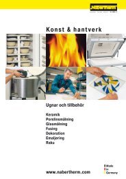
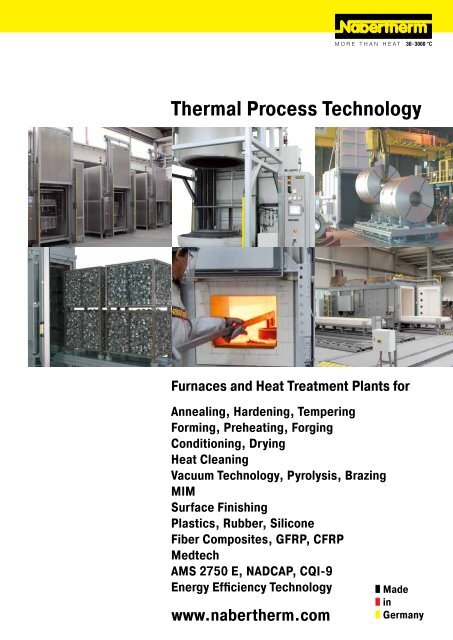
<strong>Thermal</strong> <strong>Process</strong> <strong>Technology</strong><br />
Furnaces and Heat Treatment Plants for<br />
Annealing, Hardening, Tempering<br />
Forming, Preheating, Forging<br />
Conditioning, Drying<br />
Heat Cleaning<br />
Vacuum <strong>Technology</strong>, Pyrolysis, Brazing<br />
MIM<br />
Surface Finishing<br />
Plastics, Rubber, Silicone<br />
Fiber Composites, GFRP, CFRP<br />
Medtech<br />
AMS 2750 E, NADCAP, CQI-9<br />
Energy Efficiency <strong>Technology</strong><br />
www.nabertherm.com<br />
Made<br />
in<br />
Germany
Made in Germany<br />
<strong>Nabertherm</strong> with 350 employees worldwide have been developing and producing industrial furnaces for many<br />
different applications for over 60 years. As a manufacturer, <strong>Nabertherm</strong> offers the widest and deepest range<br />
of furnaces worldwide. 150,000 satisfied customers in more than 100 countries offer proof of our commitment<br />
to excellent design, quality and cost efficiency. Short delivery times are ensured due to our complete inhouse<br />
production and our wide variety of standard furnaces.<br />
Setting Standards in Quality and Reliability<br />
<strong>Nabertherm</strong> does not only offer the widest range of standard furnaces. Professional engineering in combination<br />
with inhouse manufactoring provide for individual project planning and construction of tailor-made thermal process<br />
plants with material handling and charging systems. Complete thermal processes are realized by customized system<br />
solutions.<br />
Innovative <strong>Nabertherm</strong> control technology provides for precise control as well as full documentation and remote<br />
monitoring of your processes. Our engineers apply state-of-the-art technology to improve the temperature<br />
uniformity, energy efficiency, reliability and durability of our systems with the goal of enhancing your competitive<br />
edge.<br />
Global Sales and Service Network – Close to you<br />
Centralized engineering and manufacturing and decentralized sales and service define our strategy to live up to your<br />
needs. Long term sales and distribution partners in all important world markets ensure individual on-site customer<br />
service and consultation. There are various reference customers in your neighborhood who have similar furnaces or<br />
plants.<br />
Large Customer Test Center<br />
What furnace is the right choice for this specific process? This question cannot<br />
always be answered easily. Therefore, we have set up our modern test center<br />
which is unique in respect to size and variety. A representative number of<br />
furnaces is available for tests for our customers.<br />
Customer Service and Spare Parts<br />
Our professional service engineers are available for you world-wide. Due to our<br />
complete inhouse production, we can despatch most spare parts from stock over<br />
night or produce with short delivery time.<br />
Experience in Many Fields of <strong>Thermal</strong> <strong>Process</strong>ing<br />
In addition to furnaces for thermal process technology, <strong>Nabertherm</strong> offers a wide range of standard furnaces and<br />
plants for many other thermal processing applications. The modular design of our products provides for customized<br />
solutions to your individual needs without expensive modifications.<br />
2
Table of Contents<br />
Page<br />
Which Furnace for Which <strong>Process</strong>?....................................................................................................... 4<br />
Brazing, Forming, Plastics.................................................................................................................... 8<br />
Retort Furnaces<br />
Hot-wall retort furnaces up to 1100 °C......................................................................................................10<br />
Cold-wall retort furnaces up to 2400 °C....................................................................................................14<br />
Pit-type cold-wall retort furnaces up to 2400 °C or up to 3000 °C................................................................ 18<br />
Lift-bottom-retort furnace up to 2400 °C for production..............................................................................19<br />
Air Circulation Furnaces<br />
Air circulation chamber furnaces < 675 liters, electrically heated................................................................ 20<br />
Air circulation chamber furnaces > 560 liters, electrically heated or gas-fired............................................... 22<br />
Chamber dryer, electrically heated or gas-fired........................................................................................ 26<br />
Ovens, also with safety technology according to EN 1539, electrically heated............................................... 28<br />
Air circulation chamber furnaces/ovens with safety technology for solvent-containing charges<br />
according to EN 1539 or NFPA 86........................................................................................................ 30<br />
Clean room solutions.............................................................................................................................31<br />
Chamber furnaces for heat cleaning, gas-fired with integrated thermal afterburner........................................ 32<br />
Air circulation pit-type furnaces, electrically heated.................................................................................. 33<br />
Pit-type and top-loading furnaces with or without air circulation, electrically heated or gas-fired...................... 35<br />
Air circulation bogie hearth furnaces, electrically heated or gas-fired........................................................... 36<br />
Bogie Hearth Furnaces<br />
Bogie hearth furnaces, electrically heated............................................................................................... 38<br />
Bogie hearth furnaces, gas-fired.............................................................................................................41<br />
Chamber Furnaces<br />
Chamber furnaces, also for heat cleaning, gas-fired.................................................................................. 42<br />
Chamber furnaces, electrically heated.................................................................................................... 43<br />
Lift-Top Furnaces, Electrically Heated................................................................................................ 46<br />
Charging Devices and Accessories for Chamber and Bogie Hearth Furnaces...................................... 48<br />
Quench Tanks..................................................................................................................................... 49<br />
Protective Gas and Carburization Systems for Annealing and Hardening............................................. 50<br />
Salt-Bath Furnaces for Heat Treatment of Steel or Light Metals, Electrically or Gas-Fired.............. 52<br />
Martempering Furnaces using Neutral Salts, Electrically Heated........................................................ 53<br />
Furnaces for Continuous <strong>Process</strong>es<br />
Rotary hearth furnaces up to 1300 °C with and without air circulation, electrically hated or gas-fired................ 54<br />
Continuous furnaces, electrically heated or gas-fired................................................................................ 56<br />
Wire and strand annealing furnaces........................................................................................................ 58<br />
Energy Efficiency <strong>Technology</strong>.............................................................................................................. 59<br />
Tempering Plants for Steel and NE-Metals.......................................................................................... 60<br />
Temperature Uniformity and System Accuracy.................................................................................... 64<br />
AMS 2750 E, NADCAP, CQI-9.............................................................................................................. 65<br />
<strong>Process</strong> Control and Documentation................................................................................................... 68<br />
3
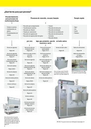
Which Furnace for Which <strong>Process</strong>?<br />
Preheating for Forging<br />
Hardening, Annealing<br />
Quenching<br />
• Press Hardening<br />
• Heating of sheet<br />
metals<br />
• Preheating of molds<br />
• Ageing<br />
• Austempering<br />
• Diffusion annealing<br />
• Pack hardening<br />
• Recovery annealing<br />
• Coarse grain annealing<br />
• Hardening<br />
• Solution annealing<br />
• Annealing<br />
• Recrystallization annealing<br />
• Stress-relieving<br />
• Soft annealing<br />
• Water<br />
• Air<br />
• Oil<br />
• Polymer<br />
in Air<br />
under Protective Gases,<br />
Reaction Gases or in Vacuum<br />
in Salt Bath<br />
Bogie hearth furnaces<br />
page 38<br />
Air circulation pit-type<br />
furnaces<br />
page 34<br />
Hot-wall retort furnaces<br />
page 10 - 13<br />
Salt-bath furnaces<br />
page 52<br />
Quench tanks<br />
page 49<br />
Bogie hearth furnaces<br />
gas-fired<br />
page 41<br />
Pit-type and top-loading<br />
furnaces<br />
page 35<br />
Cold-wall retort furnaces<br />
page 14 - 19<br />
Water quench tanks<br />
page 60 - 63<br />
Chamber furnaces<br />
gas-fired<br />
page 42<br />
Bogie hearth furnaces<br />
page 38<br />
Bogie hearth furnaces with<br />
annealing box<br />
page 38<br />
Chamber furnaces<br />
page 43/44<br />
Bogie hearth furnaces<br />
gas-fired,<br />
page 41<br />
Chamber furnaces with<br />
annealing box<br />
page 43<br />
Lift-top furnaces<br />
page 46<br />
Chamber furnaces<br />
gas-fired<br />
page 42<br />
Lift-top furnaces with<br />
annealing box<br />
page 46<br />
Salt-bath furnace TS 40/30<br />
with exhaust gas collection at<br />
crucible rim see page 52<br />
Water quench tank with powerful<br />
water-circulation<br />
Rotary hearth furnaces<br />
Chamber furnaces<br />
Rotary hearth furnaces<br />
page 54<br />
page 43/44<br />
page 54<br />
Continuous furnaces<br />
Lift-top furnaces<br />
page 56<br />
page 46<br />
Rotary hearth furnaces<br />
page 54<br />
Continuous furnaces<br />
page 56<br />
Strand annealing furnaces<br />
page 58<br />
Wire annealing furnaces<br />
page 58<br />
Annealing furnace with electro-hydraulic lift door<br />
on transportable base for preheating of large steel<br />
sheets for the automotive industry see page 44<br />
NR 200/11 H 2<br />
for operation with hydrogen see page 10<br />
4
Tempering, Annealing<br />
Heat Treatment Systems<br />
• Tempering<br />
• Precipitation annealing<br />
• Ageing<br />
• Recovery annealing<br />
• Solution annealing<br />
• Preheating<br />
• Reduced hydrogen annealing<br />
• Solution annealing<br />
• Quenching<br />
• Artificial ageing<br />
in Air<br />
under Protective Gases,<br />
Reaction Gases or in Vacuum<br />
in Salt Bath<br />
Chamber dryers<br />
page 26<br />
Hot-wall retort furnaces<br />
page 10 - 13<br />
Martempering furnaces<br />
page 53<br />
Fully automatic tempering<br />
systems<br />
page 60/61<br />
Air circulation chamber<br />
furnaces > 560 liters<br />
page 22<br />
Air circulation chamber<br />
furnaces with annealing<br />
box, page 20<br />
Manual heat treatment<br />
systems<br />
page 62/63<br />
Air circulation chamber<br />
furnaces < 675 liters<br />
page 20<br />
Air circulation chamber<br />
furnaces with annealing<br />
box, page 31<br />
Air circulation chamber<br />
furnaces with cleanroom<br />
technology, page 31<br />
Air circulation bogie<br />
hearth furnaces with<br />
annealing box, page 36<br />
Air circulation bogie<br />
hearth furnaces<br />
page 36<br />
Air circulation pit-type<br />
furnaces with annealing<br />
box, page 33<br />
Air circulation pit-type<br />
furnaces<br />
page 33/34<br />
Rotary hearth furnaces<br />
page 54<br />
Pit-type and top-loading<br />
furnaces<br />
page 35<br />
Continuous furnaces<br />
page 56<br />
Rotary hearth furnaces<br />
page 54<br />
Continuous furnaces<br />
Manual heat treatment system for hardening of steel rods see page 62/63<br />
page 56<br />
Temperature<br />
Program Step<br />
Time<br />
x min.<br />
x min.<br />
x min.<br />
x min.<br />
x min.<br />
Evacuation<br />
Waiting<br />
Pressure test<br />
x min.<br />
x min.<br />
x min.<br />
x min.<br />
x min.<br />
x min.<br />
x min.<br />
x min.<br />
x min.<br />
x min.<br />
Filling-up<br />
Waiting<br />
Test Over-<br />
Pressure<br />
Filling-up<br />
Heating<br />
Heating/Heat<br />
Transfer<br />
Supply of<br />
<strong>Process</strong><br />
Gases<br />
Cooling<br />
Pressure<br />
Holding<br />
Safety<br />
Flushing<br />
Pressure<br />
Compensation<br />
Open Door<br />
Atmosphere<br />
<strong>Process</strong> flow chart<br />
5
Which Furnace for Which <strong>Process</strong>?<br />
Brazing/Soldering<br />
Curing, Tempering, Drying<br />
• Soft soldering<br />
• Brazing<br />
• High-temperature brazing<br />
• Dip brazing of steel<br />
• Dip brazing of aluminum<br />
• Composites<br />
• Molds<br />
• Adhesive<br />
• Plastics<br />
• Lacquers<br />
• PTFE<br />
• Silicone<br />
• Surface Drying<br />
• Preheating<br />
• Vulcanizing<br />
• Conditioning<br />
under Protective<br />
Gases<br />
in Salt Bath<br />
in Vacuum<br />
Solvent Based<br />
Water Based<br />
Hot-wall retort furnaces<br />
Salt-bath furnaces<br />
Hot-wall retort furnaces<br />
Hot-wall retort furnaces<br />
Chamber dryers<br />
page 10 - 13<br />
page 52<br />
page 10 - 13<br />
page 10 - 13<br />
page 26<br />
Cold-wall retort furnaces<br />
page 14 - 19<br />
Cold-wall retort furnaces<br />
page 14 - 19<br />
Chamber dryers<br />
page 26<br />
Air circulation chamber<br />
furnaces<br />
page 20<br />
Air circulation chamber<br />
furnaces with annealing<br />
box, page 20<br />
Air circulation chamber<br />
furnaces EN 1539<br />
page 30<br />
Ovens<br />
page 28<br />
Chamber furnaces with<br />
annealing box,<br />
page 43<br />
Air circulation bogie<br />
hearth furnaces<br />
page 36<br />
Air circulation pit-type<br />
furnaces<br />
page 33/34<br />
Rotary hearth furnaces<br />
page 54<br />
Continuous furnaces<br />
page 56<br />
Brazing in a gas-supply box VHT 500/22-GR H 2<br />
with graphite insulation and heating see page 14<br />
6
Surface Treatment<br />
<strong>Thermal</strong>/Thermo-Chemical <strong>Process</strong>es<br />
Sintering & Debinding<br />
• Carburizing<br />
• Blueing (e.g. with water steam)<br />
• Nitriding/nitrocarborizing<br />
• Oxidizing<br />
• Deoxidizing under hydrogen<br />
• Heat cleaning<br />
• Pyrolysis<br />
• Debinding<br />
• MIM<br />
• CIM<br />
• Sintering<br />
in Salt Bath<br />
under Protective<br />
Gases, Reaction Gases<br />
in Powders<br />
under Protective Gases,<br />
Reaction Gases or in Vacuum<br />
Salt-bath furnaces<br />
Hot-wall retort furnaces<br />
Hot-wall retort furnaces<br />
Hot-wall retort furnaces,<br />
page 52<br />
page 10 - 13<br />
page 10 - 13<br />
page 10 - 13<br />
Cold-wall retort furnaces<br />
Cold-wall retort furnaces<br />
Cold-wall retort furnaces,<br />
page 14 - 19<br />
page 14 - 19<br />
page 14 - 19<br />
Air circulation chamber<br />
furnaces with annealing<br />
box, page 20<br />
Air circulation chamber<br />
furnaces<br />
page 20<br />
Retort furnaces for<br />
catalytic debinding, see<br />
separate catalog:<br />
Air circulation bogie<br />
hearth furnaces with<br />
annealing box, page 36<br />
Bogie hearth furnaces<br />
page 38<br />
Bogie hearth furnaces with<br />
annealing box<br />
page 38<br />
Bogie hearth furnaces<br />
gas-fired<br />
page 41<br />
Chamber furnaces with<br />
annealing box<br />
page 43<br />
Chamber furnaces<br />
gas-fired<br />
page 42<br />
Overview<br />
annealing boxes<br />
page 50<br />
Chamber furnaces<br />
page 43/44<br />
Lift-top furnaces<br />
page 46<br />
Overview<br />
annealing boxes<br />
page 50<br />
Blueing of drills in water steam atmosphere in a furnace of the NRA range<br />
see page 12<br />
Sintering of MIM titan parts in a VHT furnace<br />
7
Brazing, Forming, Plastics<br />
The furnaces shown in this catalog can be used for various heat treatment processes. <strong>Nabertherm</strong> has developed<br />
interesting solutions for the processes described below as examples:<br />
Brazing in annealing box<br />
Brazing<br />
In general, when speaking of brazing we have to distinguish between soft-soldering, brazing and high-temperature<br />
brazing. This involves a thermal process for forming substance-to-substance bonds and material coatings during<br />
which a liquid phase is generated by the melting of the solder. Based on their melting temperatures, the solder<br />
processes are classified as follows:<br />
Soft-solders: Tliq < 450 °C<br />
Brazing: Tliq > 450 °C < 900 °C<br />
High-temperature brazing: Tliq > 900 °C<br />
Beside the right selection of the solder, the flux if necessary, and ensuring that the surfaces are clean, the choice<br />
of the right brazing furnace is also key to the process. In addition to the actual brazing process, <strong>Nabertherm</strong> has<br />
furnaces for the preparation process in their range such as for metallizing ceramics in preparation for brazing<br />
ceramic-to-metal bonds.<br />
Hot-wall retort furnace to 1100 °C<br />
The following furnace concepts are available for brazing:<br />
• Brazing in an annealing box in the air circulation chamber furnace up to 850 °C in a protective gas atmosphere<br />
• Brazing in an annealing box in a chamber furnace up to 1100 °C under a protective gas atmosphere<br />
• Brazing in a hot-wall retort furnace NR/NRA product line under protective gases or reaction gas up to 1100 °C<br />
• Brazing in a cold-wall retort furnace VHT product line under protective gases, reaction gases or under vacuum up<br />
to 2200 °C<br />
• Brazing in a salt bath up to 1000 °C salt bath temperature<br />
• Brazing or metallizing in a tube furnace up to 1800 °C under protective gases, reaction gases or in a vacuum up<br />
to 1400 °C (see separate Advanced Materials catalog)<br />
In the <strong>Nabertherm</strong> Test Center in Lilienthal, Germany, a range of sample furnaces is available for customers testing<br />
applications which is the best approach to define the right furnace for a specific application.<br />
N 6080/13 S with door-in-door function,<br />
isolating transformer and vibration dampers<br />
Pre-Heating for Hot Forming<br />
For traditional hot forming processes such as forging or die forming the piece must first be heated to a defined<br />
temperature. From the manufacture of individual parts to serial production, from thin metal sheets to components<br />
which are formed in the course of multiple passes – <strong>Nabertherm</strong> offers a broad range of furnaces and special<br />
solutions for these processes.<br />
If, for example, only the ends of long components need to be heated, the furnace can be fitted with closable<br />
openings in the door to avoid any heat losses. To protect the operator, an isolating transformer is used which safely<br />
conducts away the electrical currents in case of touching the heating elements.<br />
N 1760/S for pre-heating sheet metalssteel<br />
with charge support<br />
If the furnace is used near a forging hammer which causes strong vibrations, vibration dampers can be installed to<br />
separate the furnace from these frequencies. The needs of continuous forging processes are met by appropriate<br />
furnace models such as rotary hearth furnaces and continuous furnaces. The advantage of the rotary hearth furnace<br />
is its compact size and the charging/discharging of the work piece at one position.<br />
If the task is to form sheet steel, for example in the automotive industry, the furnace needs a large width and depth<br />
in relation to its height. For easy charging, the furnaces are provided with a lift door and can, if necessary, be fitted<br />
with a charge support adapted for use with the charging stacker.<br />
DH 2500/ S on rails to shuttle between two<br />
forging stations<br />
8
Tempering, Curing, Vulcanization and Degassing of Plastics, Rubber, Silicone, and<br />
Fiber Composite Materials<br />
Many plastics and fiber composite materials must be heat-treated for product improvement or to ensure that they<br />
have the required product properties. In most cases, chamber dryers or ovens with air circulation are used for the<br />
respective process. The following examples outline the processes which these furnaces can perform.<br />
PTFE (polytetrafluoroethylene)<br />
One application is the heat treatment of PTFE. This process can be used to improve the adhesive properties, the<br />
mixture hardness or the sliding properties of the coating. In most cases, chamber dryers are used which, depending<br />
on the type of plastic, may or may not include safety technology based on EN 1539.<br />
Silicone<br />
One reason why silicone is tempered is to reduce the amount of silicone oil in the silicone to a certain percentage,<br />
i.e. to drive it out, in order to meet relevant food regulations. During the tempering process the silicone oil is vented<br />
out of the furnace chamber by continuous air exchange. To optimize the temperature uniformity in the furnace<br />
chamber, the fresh air supply is preheated. Depending on the furnace size, a heat-recovery system with heat<br />
exchangers can result in significant energy savings and pay for itself in just a short time.<br />
Silicone tempering furnace with tightly<br />
welded inner box and rotating rack for the<br />
charge.<br />
Parts are prevented from sticking together by keeping them moving in a rotating rack in the oven.<br />
Carbon Composite Materials<br />
These days, carbon composite materials are used in many industries such as automotive, aerospace, wind power,<br />
agriculture, etc. Different materials and manufacturing processes require different heat-treatment processes for<br />
curing composite materials.<br />
Some of the processes are done in autoclaves. Other materials are heat-treated in chamber dryers or ovens with<br />
air circulation. In this case, the composite materials are frequently evacuated in vacuum bags. For this purpose, the<br />
furnace is equipped with suitable connections for the evacuation of the air bags.<br />
Pages 6/7 contain a description of which <strong>Nabertherm</strong> furnace ranges are suitable for tempering and curing of<br />
plastics.<br />
The openings for the vacuum and measurement<br />
connections of an air circulation<br />
chamber furnace<br />
Chamber dryer KTR 2000 for silicone tempering<br />
Drawer system for charging the furnace on<br />
several levels.<br />
9
Hot-Wall Retort Furnaces up to 1100 °C<br />
NR 75/06 with automatic gas injection and<br />
touch panel H 3700<br />
NR 17/06 with gas supply system<br />
NRA 17/06 - NRA 1000/11<br />
These gas tight retort furnaces are equipped with direct or indirect heating depending on temperature. They are<br />
perfectly suited for various heat treatment processes requiring a defined protective or a reaction gas atmosphere.<br />
These compact models can also be laid out for heat treatment under vacuum up to 600 °C. The furnace chamber<br />
consists of a gas tight retort with water cooling around the door to protect the special sealing. Equipped with the<br />
corresponding safety technology, retort furnaces are also suitable for applications under reaction gases, such as<br />
hydrogen or, in combination with the IDB package, for inert debinding or for pyrolysis processes.<br />
Inside heating in models NRA ../06<br />
Different model versions are available depending on the temperature range required for the process:<br />
Models NRA ../06 with Tmax 650 °C<br />
• Heating elements located inside the retort<br />
• Temperature uniformity up to ∆T 6 K inside the working chamber from 100 °C - 600 °C see page 64<br />
• Retort made of 1.4571<br />
• Gas circulation fan in the back of the retort provides for optimal temperature uniformity<br />
Models NRA ../09 with Tmax 950 °C<br />
• Outside heating with heating elements surrounding the retort as well as an additional door heater<br />
• Temperature uniformity up to ∆T 6 K inside the working chamber from 200 °C - 900 °C see page 64<br />
• Retort made of 1.4841<br />
• Fan in the back of the retort provides for optimal temperature uniformity<br />
Heating from outside around the retort in<br />
models NRA ../09 and NR ../11<br />
Models NR ../11 with Tmax 1100 °C<br />
• Outside heating with heating elements surrounding the retort as well as an additional door heater<br />
• Temperature uniformity up to ∆T 10 K inside the working chamber from 200 °C - 1050 °C see page 64<br />
• Retort made of 1.4841<br />
10
NRA 480/04S<br />
Basic version<br />
• Compact housing in frame design with removable stainless steel sheets<br />
• Controls and gas supply integrated in the furnace housing<br />
• Welded charging supports in the retort or air-baffle box in the furnace with air circulation<br />
• Swivel door hinged on right side with open cooling water system<br />
• Multi-zone control for 950 °C and 1100 °C version, separated by furnace chamber and door.<br />
Depending on furnace chamber additionally subdivided into one or several heating zones<br />
• Temperature control as charge control with temperature measurement inside and outside<br />
the retort<br />
• Gas supply system for one non-flammable protective or reaction gas with flow meter and solenoid valve,<br />
switchable via the control system<br />
• Operation under vacuum up to 600 °C with optional single-stage rotary vane pump<br />
• Port for vacuum pump for cold evacuation<br />
• PLC controls with touch panel H 700 for data input (resp. P 300 for 650 °C-version) see page 70<br />
NRA 50/09 H 2<br />
Additional equipment<br />
• Upgrade for other nonflammable gases<br />
• Automatic gas injection, including MFC flow controller for alternating volume flow, PLC controlled with touch<br />
panel H 3700<br />
• Vacuum pump for evacuating of the retort up to 600 °C, attainable vacuum up to 10 -5 mbar subject to selected<br />
pump<br />
• Cooling system for shortening process times<br />
• Heat exchanger with closed-loop cooling water circuit for door cooling<br />
• Measuring device for residual oxygen content<br />
Vacuum pump for cold evacuation of the<br />
retort<br />
Touchpanel H 3700 for automatic version<br />
11
Charging of the NR 300/06 furnace with a pallet truck<br />
NR 200/11 H 2<br />
for heat treatment under<br />
hydrogen<br />
H 2<br />
Version for Operation under Hydrogen<br />
When hydrogen is used as a process gas, the furnace is additionally equipped with the required safety technology.<br />
Only certified and industry proven safety sensors are used. The furnace is controlled by a fail-safe PLC control<br />
system (S7- 300F/safety controller).<br />
Bayonet quick-lock for the retort, also with<br />
electric drive as additional equipment<br />
• H 2<br />
supply at controlled overpressure of 50 mbar relative<br />
• Certified safety concept<br />
• PLC controls with graphic touch panel H 3700 for data input<br />
• Redundant gas inlet valves for hydrogen<br />
• Monitored pre-pressures of all process gases<br />
• Bypass for safe flushing of furnace chamber with inert gas<br />
• Torch for thermal afterburning of exhaust gases<br />
• Emergency flood container for purging the furnace in case of failore<br />
IDB Version for Debinding under Non-flammable Protective Gases or for Pyrolysis <strong>Process</strong>es<br />
The retort furnaces of the NR and NRA product line are perfectly suited for debinding under non-flammable<br />
protective gases or for pyrolysis processes. The IDB version of the furnaces implements a safety concept by<br />
controlled purging the furnace chamber with a protective gas. Exhaust gases are burned in an exhaust torch. Both<br />
the purging and the torch function are monitored to ensure a safe operation.<br />
Parallel guided door to open the hot furnace<br />
as additional equipment<br />
• <strong>Process</strong> control under monitored and controlled overpressure of 50 mbar relative<br />
• Certified safety concept<br />
• PLC controls with graphic touch panel H 1700 for data input<br />
• Monitored gas pre-pressure of the process gas<br />
• Bypass for safe flushing of furnace chamber with inert gas<br />
• Torch for thermal afterburning of exhaust gases<br />
Blueing of drills in water steam atmosphere<br />
in a furnace of the NRA range<br />
12<br />
Model Tmax Model Tmax Working chamber dimensions in mm Useful volume Electrical<br />
°C °C w d h in l connection*<br />
NRA 17/.. 650 or 950 NR 17/11 1100 225 350 225 17 3-phase<br />
NRA 25/.. 650 or 950 NR 25/11 1100 225 500 225 25 3-phase<br />
NRA 50/.. 650 or 950 NR 50/11 1100 325 475 325 50 3-phase<br />
NRA 75/.. 650 or 950 NR 75/11 1100 325 700 325 75 3-phase<br />
NRA 150/.. 650 or 950 NR 150/11 1100 450 750 450 150 3-phase<br />
NRA 200/.. 650 or 950 NR 200/11 1100 450 1000 450 200 3-phase<br />
NRA 300/.. 650 or 950 NR 300/11 1100 570 900 570 300 3-phase<br />
NRA 400/.. 650 or 950 NR 400/11 1100 570 1250 570 400 3-phase<br />
NRA 500/.. 650 or 950 NR 500/11 1100 720 1000 720 500 3-phase<br />
NRA 700/.. 650 or 950 NR 700/11 1100 720 1350 720 700 3-phase<br />
NRA 1000/.. 650 or 950 NR 1000/11 1100 870 1350 870 1000 3-phase<br />
*Please see page 70 for more information about supply voltage
SRA 17/.. - SR 1500<br />
The retort furnaces SR and SRA (with gas circulation) are designed for operation<br />
with non-flammable or flammable protective or reaction gases. The furnace<br />
is loaded from above by crane or other lifting equipment provided by the<br />
customer. In this way, even large charge weights can be loaded into the<br />
furnace chamber. The SR furnaces are available in different versions.<br />
Depending on the temperature range in which the furnace be used, the<br />
following models are available:<br />
Models SR .../11 with Tmax 1100 °C<br />
• Heating from all sides outside the retort<br />
• Temperature uniformity up to ∆T 14 K according to DIN 17052-1 within the<br />
working chamber of 500 °C - 1100 °C see page 64<br />
• Retort made of 1.4841<br />
• Top down multi-zone control of the furnace heating<br />
Models SRA ../09 with Tmax 950 °C<br />
Design like models SR…/11 with following differences:<br />
• Atmosphere circulation with powerful fan in the furnace lid provides for<br />
temperature uniformity of up to ∆T 8 K according to DIN 17052-1 within the<br />
working chamber of 200 °C - 900 °C see page 64<br />
Models SRA ../06 with Tmax 600 °C<br />
Design like models SRA…/09 with following differences:<br />
• Heating inside the retort<br />
• Temperature uniformity up to ∆T 14 K according to DIN 17052-1 within the<br />
working chamber of 100 °C - 600 °C see page 64<br />
• Single-zone control<br />
• Retort made of 1.4841<br />
SRA 200/09<br />
Standard Equipment (all models)<br />
Design like standard equipment of models NR and NRA with following differences:<br />
• Charging from above with crane or other lifting equipment from customer<br />
• Hinged lid with opening to the side<br />
Additional equipment, H 2<br />
version or IDB version see models NR and NRA<br />
Model Tmax Inner dimensions of alloy retort Volume Outer dimensions in mm Heating power in kW 1 Electrical Weight<br />
°C Ø in mm h in mm in l W D H 600 °C 950 °C connection* in kg<br />
SRA 17/.. 250 350 17 1300 1700 1800 15 20 3-phase 600<br />
SRA 25/.. 250 500 25 1300 1900 1800 20 25 3-phase 800<br />
SRA 50/.. 400 450 50 1400 2000 1800 36 35 3-phase 1300<br />
SRA 100/.. 600 400 800 100 1400 2000 2100 45 65 3-phase 1500<br />
SRA 200/.. or 600 700 200 1600 2200 2200 60 90 3-phase 2100<br />
SRA 300/.. 950 600 1000 300 1600 2200 2500 75 120 3-phase 2400<br />
SRA 500/.. 800 1000 500 1800 2400 2700 70 170 3-phase 2800<br />
SRA 600/.. 800 1200 600 1800 2400 2900 90 190 3-phase 3000<br />
SRA 800/.. 1000 1000 800 2000 2600 2800 105 220 3-phase 3100<br />
SRA 1000/.. 1000 1300 1000 2000 2600 3100 120 250 3-phase 3300<br />
SRA 1500/.. 1200 1300 1500 2200 2800 3300 150 300 3-phase 3500<br />
SR 17/11 1100 250 350 17 1300 1700 1800 22 3-phase 600<br />
SR 25/11 1100 250 500 25 1300 1900 1800 27 3-phase 800<br />
SR 50/11 1100 400 450 50 1400 2000 1800 40 3-phase 1300<br />
SR 100/11 1100 400 800 100 1400 2000 2100 73 3-phase 1500<br />
SR 200/11 1100 600 700 200 1600 2200 2200 98 3-phase 2100<br />
SR 300/11 1100 600 1000 300 1600 2200 2500 132 3-phase 2400<br />
SR 500/11 1100 800 1000 500 1800 2400 2700 182 3-phase 2800<br />
SR 600/11 1100 800 1200 600 1800 2400 2900 205 3-phase 3000<br />
SR 800/11 1100 1000 1000 800 2000 2600 2800 235 3-phase 3100<br />
SR 1000/11 1100 1000 1300 1000 2000 2600 3100 268 3-phase 3300<br />
SR 1500/11 1100 1200 1300 1500 2200 2800 3300 315 3-phase 3500<br />
1<br />
Depending on furnace design connected load might be higher *Please see page 70 for more information about supply voltage<br />
Retort furnace SRA 300/09<br />
13
Cold-Wall Retort Furnaces up to 2400 °C<br />
VHT 500/22-GR H 2<br />
with CFC-process box<br />
and extension package for operation under<br />
hydrogen<br />
VHT 8/18-GR - VHT 500/18-KE<br />
The compact furnaces of the VHT product line are available as electrically heated chamber furnaces with graphite,<br />
molybdenum, tungsten or MoSi 2<br />
heating. A wide variety of heating designs as well as a complete range of<br />
accessories provide for optimal furnace configurations even for sophisticated applications.<br />
The vacuum-tight retort allows heat treatment processes either in protective and reaction gas atmospheres or in a<br />
vacuum, subject to the individual furnace specs to 10 -5 mbar. The basic furnace is suited for operation with nonflammable<br />
protective or reactive gases or under vacuum. The H 2<br />
version provides for operation under hydrogen or<br />
other flammable gases. Key of the specification up is a certified safety package providing for a safe operation at all<br />
times and triggers an appropriate emergency program in case of failure.<br />
Alternative Heating Specifications<br />
The following heating systems are available for the different application temperatures:<br />
VHT ../GR with Graphite Insulation and Heating<br />
• Suitable for processes under protective and reaction gases or under vacuum<br />
• Tmax 1800 °C or 2200 °C (2400 °C as additional equipment)<br />
• Max. vacuum up to 10 -4 mbar depending on pump type used<br />
• Graphite felt insulation<br />
VHT 8/18-KE with fiber insulation and<br />
molybdenum disilicide heating elements<br />
VHT ../MO or ../W with Molybdenum or Tungsten Heating<br />
• Suitable for high-purity processes under protective and reaction gases or under high vacuum<br />
• Tmax 1200 °C, 1600 °C or 1800 °C (see table)<br />
• Max. vacuum up to 5 x 10 -5 mbar depending on pump type used<br />
• Insulation made of molybdenum rsp. tungsten radiation sheets<br />
Heat treatment of copper bars under hydrogen<br />
in VHT 08/16 MO<br />
VHT ../KE with Fiber Insulation and Heating through Molybdenum Disilicide Heating Elements<br />
• Suitable for processes under protective and reaction gases, in air or under vacuum<br />
• Tmax 1800 °C<br />
• Max. vacuum up to 10 -2 mbar (up to 1300 °C) depending on pump type<br />
• Insulation made of high purity aluminum oxide fiber<br />
14
Standard Equipment for all Models<br />
Basic version<br />
• Standard furnace sizes 8 - 500 liters<br />
• A water-cooled stainless steel process reactor sealed with temperature-resistant o-rings<br />
• Frame made of stable steel profiles, easy to service due to easily removable stainless steel panels<br />
• Housing of the VHT 8 model on castors for easy repositioning of furnace<br />
• Cooling water manifold with manual stopcocks in supply and return lines, automatic flowmeter monitoring,<br />
openloop cooling water system<br />
• Adjustable cooling water circuits with flowmeter and temperature indicator and overtemperature fuses<br />
• Switchgear and controller integrated in furnace housing<br />
• H 700 PLC control with clearly laid out 5.7“ touchpanel control for program entry and display, 10 programs each<br />
with 20 segments<br />
• Over-temperature limiter with manual reset for thermal protection class in accordance with EN 60519-2<br />
• Manual operation of the process gas and vacuum functions<br />
• Manual gas supply for one process gas (N 2<br />
or Ar) with adjustable flow<br />
• Bypass with manual valve for rapid filling or flooding of furnace chamber<br />
• Manual gas outlet with overflow valve (20 mbar relative)<br />
• Single-stage rotary vane pump with ball valve for pre-evacuating and heat treatment in a rough vacuum to 5 mbar<br />
• Pressure gauge for visual pressure monitoring<br />
Additional equipment<br />
• Tmax 2400 °C<br />
• Housing, optionally divisible, for passing through narrow door frames (VHT 08)<br />
• Manual gas supply for second process gas (N 2<br />
or Ar) with adjustable flow and bypass<br />
• Inner process box made of molybdenum, tungsten or CFC, especially recommended for debinding processes.<br />
The box is installed in the furnace with direct gas inlet and outlet and provides for better temperature uniformity.<br />
Due to a change in gas supply direction after debinding a clean process atmosphere for sintering is achieved.<br />
• Charge thermocouple with display<br />
• Temperature measurement at 2200 °C models with pyrometer and thermocouple, type S with automatic pull-out<br />
device for precise control results in the low temperature range (VHT 40 and larger)<br />
• Two-stage rotary vane pump with ball valve for pre-evacuating and heat-treating in a vacuum to 10 -2 mbar<br />
• Turbo molecular pump with slide valve for pre-evacuation and for heat treatment in a vacuum to 10 -5 mbar<br />
including electric pressure transducer and booster pump (only VHT…/MO)<br />
• Other pumps on request<br />
• Heat exchanger with closed-loop cooling water circuit<br />
• Automation package with graphic touch panel H 3700<br />
--12" graphic touch panel H 3700<br />
--Input of all process data like temperatures, heating rates, gas injection, vacuum at the touch panel<br />
--Display of all process-relevant data on a process control diagram<br />
--Automatic gas supply for one process gas (N 2<br />
, argon or forming gas) with adjustable flow<br />
--Bypass for flooding and filling the chamber with process gas controlled by the program<br />
--Automatic pre- and post programs, including leak test for safe furnace operation<br />
--Automatic gas outlet with bellows valve and overflow valve (20 mbar)<br />
--Transducer for absolute and relative pressure<br />
• MFC flow controller for alternating volume flow and generation of gas mixtures with second process gas (only<br />
with automation package)<br />
• Partial pressure operation: protective gas flushing at controlled underpressure (only with automation package)<br />
• PC control via NCC with corresponding optional documentation and connection to customer PC networks<br />
Graphite heating chamber<br />
Molybdenum heating chamber<br />
Tungsten heating chamber<br />
Ceramic fiber insulation<br />
Thermocouple, type S with automatic pullout<br />
device for precise control results in the<br />
low temperature range<br />
15
VHT 40/16MO H 2<br />
VHT 40/22 GR with motor-driven lift door<br />
and front frame for connection to a glove<br />
box<br />
H 2<br />
Version for Operation with Hydrogen or other Reaction Gases<br />
In the H 2<br />
version the furnaces can be operated under hydrogen or other reaction gases. For these applications, the<br />
systems are additionally equipped with the required safety technology. Only certified and industry proven safety<br />
sensors are used. The furnaces are controlled by a fail-safe PLC control system (S7-300F/safety controller).<br />
Turbo-molecular pump<br />
• Certified safety concept<br />
• Automation package (see additional equipment above)<br />
• Redundant gas inlet valves for hydrogen<br />
• Monitored pre-pressures of all process gases<br />
• Bypass for safe purging of furnace chamber with inert gas<br />
• Pressure-monitored emergency flooding with automated solenoid valve opening<br />
• Electric or gas-heated exhaust gas torch for H 2<br />
post-combustion<br />
• Atmospheric operation: H 2<br />
-purging of process reactor starting from room temperature at controlled over pressure<br />
(50 mbar relative)<br />
Additional equipment<br />
• Partial pressure operation: H 2<br />
flushing at underpressure in the process reactor starting from 750 °C furnace<br />
chamber temperature<br />
• Retort in the process chamber for debinding under hydrogen<br />
VHT gas supply diagram, debinding and<br />
sintering<br />
Single-stage rotary vane pump for heat treatment in<br />
a rough vacuum to 20 mbar<br />
16<br />
Two-stage rotary vane pump for heat treatment in a<br />
vacuum to 10 -2 mbar<br />
Turbo-molecular pump with booster pump for heat<br />
treatment in a vacuum to 10 -5 mbar
<strong>Process</strong> Box for Debinding in Inert Gas<br />
Certain processes require charges to be debinded in non-flammable<br />
protective or reactive gases. For these processes we fundamentally<br />
recommend a hot-wall retort furnace (see models NR… or SR…).<br />
These furnaces can ensure that the formation of condensation will be<br />
avoided as throughly as possible.<br />
If there is no way to avoid the escape of small amounts of residual<br />
binder during the process, even in the VHT furnace, the furnace should<br />
be designed to meet this contingency.<br />
The furnace chamber is equipped with an additional process box<br />
that has a direct outlet to the exhaust gas torch through which the<br />
exhaust gas can be directly vented. This system enables a substantial<br />
reduction in the amount of furnace chamber contamination caused by<br />
the exhaust gases generated during debinding.<br />
Depending on the exhaust gas composition the exhaust gas line can<br />
be designed to include various options.<br />
• Exhaust gas torch for burning off the exhaust gas<br />
• Condensation trap for separating out binding agents<br />
• Exhaust gas post-treatment, depending on the process, via<br />
scrubbers<br />
• Heated exhaust gas outlet to avoid condensation deposits in the<br />
exhaust gas line<br />
VHT ...-../GR VHT ...-../MO VHT ...-18/W VHT ...-18/KE<br />
Tmax 1800 °C or 2200 °C 1200 °C or 1600 °C 1800 °C 1800 °C<br />
Inert gas <br />
Air/Oxygen up to 350 °C - - <br />
Hydrogen 3 3 3 1,3<br />
Rough vacuum and fine vacuum (>10 -3 mbar) ²<br />
High vacuum (
Pit-Type Cold-Wall Retort Furnaces up to 2400 °C or up to 3000 °C<br />
SVHT 2/24-W - SVHT 9/30-GR<br />
Compared with the VHT models (page 14 ff), the furnaces of the<br />
SVHT product line offer improved performance data with regard<br />
to achievable vacuum and maximum temperature. Due to the<br />
design as pit-type furnace with tungsten heating, processes up<br />
to max. 2400 °C even in high vacuum can be implemented with<br />
models of the SVHT..-W product line. Models of the SVHT..-GR<br />
product line with graphite heating, also in pit-type design,<br />
can be operated in an inert gas atmosphere even up to max.<br />
3000 °C.<br />
SVHT 9/24-W with tungsten heating<br />
• Standard sizes with a furnace chamber of 2 or 9 liters<br />
• Designed as pit-type furnace, charged from above<br />
• Frame construction with inserted sheets of textured stainless<br />
steel<br />
• Dual shell water-cooled stainless steel container<br />
• Manual operation of process gas and vacuum functions<br />
• Manual gas supply for non-combustible process gas<br />
• A step in front of the furnace for an ergonomic charging<br />
height<br />
• Retort lid with gas-charged shock absorbers<br />
• Controls and switchgear as well as gas supply integrated in<br />
furnace housing<br />
• Further standard product characteristics see description for<br />
standard design of VHT models page 14<br />
Heating options<br />
Cylindrical retort with tungsten heating<br />
SVHT ..-GR<br />
• Applicable for processes:<br />
--under protective or reaction gases or in the vacuum up to 2200 °C<br />
--under inert gases (argon, helium) up to 3000 °C<br />
• Max. vacuum up to 10 - ³ mbar depending on the type of pump used<br />
• Heating: graphite heating elements in cylindrical arrangement<br />
• Insulation: graphite felt insulation<br />
• Temperature measurement by means of an optical pyrometer<br />
Graphite heating module<br />
SVHT ..-W<br />
• Applicable for processes under protective or reaction gases or in vacuum up to 2400 °C<br />
• Max. vacuum up to 10 - mbar depending on the type of pump used<br />
• Heating: cylindrical tungsten heating module<br />
• Insulation: tungsten and molybdenum radiant plates<br />
• Temperature measurement with optical pyrometer<br />
Additional equipment such as automatic process gas control or design for the operation with flammable gases incl.<br />
safety system see VHT models page 14.<br />
Model Tmax Working chamber Useful volume Outer dimensions in mm Heating power Electrical<br />
dimensions<br />
°C Ø x h in mm in l W D H in kW 1 connection*<br />
SVHT 2/24-W 2400 150 x 150 2,5 1400 2500 2100 55 3-phase<br />
SVHT 9/24-W 2400 230 x 230 9,5 1500 2750 2100 95 3-phase<br />
Water-cooling controls<br />
SVHT 2/30-GR 3000 150 x 150 2,5 1400 2500 2100 55 3-phase<br />
SVHT 9/30-GR 3000 230 x 230 9,5 1500 2750 2100 95 3-phase<br />
1<br />
Depending on furnace design connected load might be higher *Please see page 70 for more information about supply voltage<br />
18
Lift-Bottom -Retort Furnace up to 2400 °C for Production<br />
LBVHT 250/20-W with tungsten heating chamber<br />
LBVHT 100/16 - LBVHT 600/24<br />
The LBVHT model series with lift-bottom specification are especially<br />
suitable for production processes which require either protective<br />
or reaction gase atmosphere or a vacuum. The basic performance<br />
specifications of these models are similar to the VHT models. Their<br />
size and design with electro-hydraulically driven table facilitate<br />
charging during production. The furnaces are available in various sizes<br />
and designs. Similar like the VHT models, these furnaces can be equipped with different heating concepts.<br />
• Standard furnace sizes between 100 and 600 liters<br />
• Designed as lift-bottom retort furnace with electro-hydraulically driven table for easy and well-arranged charging<br />
• Prepared to carry heavy charge weights<br />
• Different heating concepts using<br />
--Graphite heating chamber up to Tmax 2400 °C<br />
--Molybdenum heating chamber up to Tmax 1600 °C<br />
--Tungsten heating chamber up to Tmax 2000 °C<br />
• Frame structure filled with textured stainless steel sheets<br />
• Standard design with gassing system for non-flammable protective or reaction gases<br />
• Automatic gas supply system which also allows for operation with several process gases as additional equipment<br />
• Gas supply systems for operating with hydrogen or other combustible reaction gases incl. safety package as<br />
additional equipment<br />
• Switchgear and control box as well as gassing system integrated into the furnace housing<br />
• Further product characteristics of the standard furnace as well as possible additional equipment can be found in<br />
the description of the VHT furnaces from Page 14<br />
LBVHT 600/24-GR<br />
Model Tmax Model Tmax Model Tmax Inner dimensions in mm Volume Electrical<br />
°C °C °C Ø h in l connection*<br />
LBVHT 100/16-MO 1600 LBVHT 100/20-W 2000 LBVHT 100/24-GR 2400 450 700 100 3-phase<br />
LBVHT 250/16-MO 1600 LBVHT 250/20-W 2000 LBVHT 250/24-GR 2400 600 900 250 3-phase<br />
LBVHT 600/16-MO 1600 LBVHT 600/20-W 2000 LBVHT 600/24-GR 2400 800 1200 600 3-phase<br />
*Please see page 70 for more information about supply voltage<br />
LBVHT with graphite heating chamber<br />
19
Air Circulation Chamber Furnaces < 675 Liters<br />
Electrically Heated<br />
N 60/45HAS with additional door for<br />
charging of long parts which ride out of the<br />
open door<br />
N 250/65HA with gas supply system<br />
The very good temperature uniformity of these chamber furnaces with air circulation provides for<br />
ideal process conditiones for annealing, curing, solution annealing, artificial ageing, preheating,<br />
or soft annealing and brazing. The furnaces are equipped with a suitable annealing box for soft<br />
annealing of copper or tempering of titanium, and also for annealing of steel under non-flammable<br />
protective or reaction gases. The modular furnace design allows for adaptation to specific process<br />
requirements with appropriate accessories.<br />
N 15/65HA as table-top model<br />
• Tmax 450 °C, 650 °C, or 850 °C<br />
• Heating from bottom, sides and top<br />
• Stainless steel air-baffle box in the furnace for optimum air circulation<br />
• Swing door hinged on the right side<br />
• Base frame included in the delivery, N 15/65 HA designed as table-top model<br />
• Horizontal air circulation<br />
• Temperature uniformity up to ∆T 8 K according to DIN 17052-1 (model N 15/65 HA up to ∆T 14 K) see page 64<br />
• Optimum air distribution enabled by high flow speeds<br />
• One removable tray and rails for two additional trays included in the scope of delivery (N 15/65 HA without<br />
removable tray)<br />
• Controls description see page 68<br />
Roller conveyor in furnace N 250/85HA<br />
Additional equipment (not for model N 15/65HA)<br />
• Optimization of the temperature uniformity up to ∆T 6 K according to DIN 17052-1 see page 64<br />
• Fan cooling to accelerate the cooling process<br />
• Motorized exhaust air flaps<br />
• Manual lift door<br />
• Pneumatic lift door<br />
• Adjustable air circulation for sensitive components<br />
• Additional removable trays<br />
• Roller conveyor in furnace chamber for heavy charges<br />
20
N 250/65HA with quenching bath<br />
N 120/85HAS with charging basket<br />
• Annealing boxes see page 50<br />
• Feed and charging aids see page 48<br />
• Designed for Tmax 950 °C<br />
• <strong>Process</strong> control and documentation with Controltherm MV software package see page 69<br />
Model Tmax Inner dimensions in mm Volume Outer dimensions in mm Heating Electrical Weight<br />
°C w d h in l W D H power in kW 3 connection* in kg<br />
N 30/45 HA 450 290 420 260 30 607 + 255 1175 1315 3.6 1-phase 195<br />
N 60/45 HA 450 350 500 350 60 667 + 255 1250 1400 6.6 3-phase 240<br />
N 120/45 HA 450 450 600 450 120 767 + 255 1350 1500 9.6 3-phase 310<br />
N 250/45 HA 450 600 750 600 250 1002 + 255 1636 1860 19.0 3-phase 610<br />
N 500/45 HA 450 750 1000 750 500 1152 + 255 1886 2010 28.0 3-phase 1030<br />
N 675/45 HA 450 750 1200 750 675 1152 + 255 2100 2010 28.0 3-phase 1350<br />
N 15/65 HA¹ 650 295 340 170 15 470 845 460 2.7 1-phase 55<br />
N 30/65 HA 650 290 420 260 30 607 + 255 1175 1315 6.0 3-phase ² 195<br />
N 60/65 HA 650 350 500 350 60 667 + 255 1250 1400 9.6 3-phase 240<br />
N 120/65 HA 650 450 600 450 120 767 + 255 1350 1500 13.6 3-phase 310<br />
N 250/65 HA 650 600 750 600 250 1002 + 255 1636 1860 21.0 3-phase 610<br />
N 500/65 HA 650 750 1000 750 500 1152 + 255 1886 2010 31.0 3-phase 1030<br />
N 675/65 HA 650 750 1200 750 675 1152 + 255 2100 2010 31.0 3-phase 1350<br />
N 30/85 HA 850 290 420 260 30 607 + 255 1175 1315 6.0 3-phase² 195<br />
N 60/85 HA 850 350 500 350 60 667 + 255 1250 1400 9.6 3-phase 240<br />
N 120/85 HA 850 450 600 450 120 767 + 255 1350 1500 13.6 3-phase 310<br />
N 250/85 HA 850 600 750 600 250 1002 + 255 1636 1860 21.0 3-phase 610<br />
N 500/85 HA 850 750 1000 750 500 1152 + 255 1886 2010 31.0 3-phase 1030<br />
N 675/45 HA 850 750 1200 750 675 1152 + 255 2100 2010 31.0 3-phase 1350<br />
¹Table-top model see page 20<br />
²Heating only beetween two phases<br />
*Please see page 70 for more information about supply voltage<br />
3<br />
Depending on furnace design connected load might be higher<br />
Air circulation furnace N 500/HAS with four<br />
compartments, each with roller conveyor<br />
and individual door<br />
21
Air Circulation Chamber Furnaces > 560 Liters<br />
Electrically Heated or Gas-Fired<br />
N 1500/85HA with electric charging<br />
system for heavy loads<br />
N 3920/26HAS<br />
These air circulation chamber furnaces are available for maximum operating temperatures of 260 °C, 450 °C, 600 °C<br />
or 850 °C and are perfectly suited for demanding processes. Due to their robust and solid design even heavy loads<br />
can be heat treated. These furnaces are suited for use with baskets, pallets, and mobile furnace racks. The charging<br />
can be carried out with fork lift, pallet truck, or charging trolley. The basic furnace is standing on the shop floor<br />
without floor insulation. Charging can be simplified by roller conveyors, if necessary also motorized. All furnaces are<br />
available with electric or gas heating.<br />
Enclosed heater coils on electrically heated<br />
models<br />
Gas burner positioned along the furnace<br />
side<br />
Standard version for models up to 600 °C (850 °C models see page 24)<br />
• Tmax 260 °C, 450 °C or 600 °C<br />
• Electrically heated or gas-fired<br />
• Electric heating by means of heater coils<br />
• Direct gas heating or upon request with indirect gas heating with radiation tube, e.g. for heat treatment of<br />
aluminum<br />
• Optimal air circulation for your charge by means of adjustable air outlets<br />
• Horizontal air flow (type ../HA)<br />
• High air exchange for perfect heat transfer<br />
• Ground level charging without floor insulation for 260 °C models<br />
• Temperature uniformity up to ∆T 10 K according to DIN 17052-1 see page 64<br />
• Furnace chamber lined with alloy 1.4301 (DIN)<br />
• High quality mineral wool insulation provides for low outer temperatures<br />
• Inside unlocking device for furnaces with walk-in chambers<br />
• Furnace sizes suitable for common charging systems, such as pallets, baskets, etc.<br />
• Double-wing door for furnaces with an internal width of more than 1500 mm (260 °C and 450 °C models).<br />
Furnaces for higher temperatures and with smaller sizes are equipped with a single-wing door.<br />
22
N 2520/60HA with roller conveyor inside<br />
and in front of the furnace<br />
N 1500/85HA with lift door and work piece<br />
holders in the furnace<br />
• Over-temperature limiter with manual reset for thermal protection class 2 in accordance with EN 60519-2 as<br />
temperature limiter to protect the furnace and load<br />
• Controls description see page 68<br />
Additional equippment for models up to 600 °C<br />
• Optional floor insulation provides for improved temperature uniformity for 260 °C models<br />
• Entry ramps or track cutouts for floor-level charging cart of models with bottom insulation (not for 600 °C models)<br />
• Furnace positioned on base frame provides for ergonomic charging height<br />
• Electro-hydraulic lift door<br />
• Fan system for faster cooling with manual or motor-driven control<br />
• Motor-driven control of air inlet and exhaust air flaps for better ventilation of the furnace chamber<br />
• Observation window and/or furnace chamber lighting (not for 600 °C models)<br />
• Optimization of the temperature uniformity up to +/- 3 °C according to DIN 17052-1 see page 64<br />
• Safety technology according to EN 1539 for charges containing solvents (not for 600 °C models) see page 30<br />
• Charging systems or roller conveyors, also electrically driven provide for easy charging see page 48<br />
• Catalytic or thermal exhaust gas cleaning systems<br />
• <strong>Process</strong> control and documentation with Controltherm MV software package see page 69<br />
Pull-out drawers for heavy loads<br />
Track cutouts for pallet truck or charging<br />
cart<br />
23
Air Circulation Chamber Furnaces > 560 Liters<br />
Electrically Heated or Gas-Fired<br />
Air circulation chamber furnace N 140000/26AS for curing of composites in vacuum bags incl. pump and necessary connections in the oven chamber<br />
Air circulation furnace N 790/65HAS, adjustable<br />
in height, for integration in a heat<br />
treatment system<br />
Standard version for models 850 °C<br />
• Tmax 850 °C<br />
• Electrically heated or gas-fired<br />
• Electric heating with heating elements on supports tubes<br />
• Direct gas heating into the outlet of the air circulation fan<br />
• Optimal air circulation for your charge by means of adjustable air outlets<br />
• Horizontal air-flow (type ../HA)<br />
• High air exchange provides for perfect heat transfer<br />
• Base frame with 900 mm charging height<br />
• Temperature uniformity up to ∆T 10 K according to DIN 17052-1 see page 64<br />
• Air baffles made of 1.4828 (DIN)<br />
• Multi-layer insulation with fiber plates (not classified according to EU directive 67/548) provides for low outer<br />
temperatures<br />
• Furnaces sizes perfectly suited to accommodate common charging systems, e.g. like pallets or pallet boxes<br />
• Over-temperature limiter with manual reset for thermal protection class 2 in accordance with EN 60519-2 as<br />
temperature limiter to protect the furnace and load<br />
• Controls description see page 68<br />
Additional equipment for models 850 °C<br />
• Electro-hydraulic lift door<br />
• Fan system for faster cooling with manual or motor-driven control<br />
• Motor-driven air inlet and control of exhaust air flaps for better ventilation of the furnace chamber<br />
• Optimization of the temperature uniformity up to +/- 3 °C according to DIN 17052-1 see page 64<br />
• Base frame for customized charging height<br />
• Charging systems or roller conveyors, also electrically driven provide for easy charging see page 48<br />
• Designed for Tmax 950 °C<br />
• <strong>Process</strong> control and documentation with Controltherm MV software package see page 69<br />
N 670/65HAS with quenching tank<br />
24
N 12000/25AS<br />
N 24500/20HAS<br />
Model Tmax Inner dimensions in mm Volume Outer dimensions in mm Circulation Heating Electrical<br />
°C w d h in l W D H rate m³/h power in kW 2 connection*<br />
N 560/26HA 260 750 1000 750 560 1450 1865 2220 900 13.0 3-phase<br />
N 1000/26HA 260 1000 1000 1000 1000 1930 1900 1600 3600 18.0 3-phase<br />
N 1500/26HA 260 1500 1000 1000 1500 2380 1900 1600 3600 22.0 3-phase<br />
N 1500/26HA1 260 1000 1500 1000 1500 1880 2400 1600 3600 22.0 3-phase<br />
N 2000/26HA 260 1500 1100 1200 2000 2380 2000 1800 6400 22.0 3-phase<br />
N 2000/26HA1 260 1100 1500 1200 2000 1980 2400 1800 6400 22.0 3-phase<br />
N 2010/26HA 260 1000 1000 2000 2000 1880 1900 2720 7200 30.0 3-phase<br />
N 2880/26HA 260 1200 1200 2000 2880 2080 2100 2720 9000 54.0 3-phase<br />
N 4000/26HA 260 1500 2200 1200 4000 2380 3110 1800 9000 47.0 3-phase<br />
N 4000/26HA1 260 2200 1500 1200 4000 3080 2410 1800 9000 47.0 3-phase<br />
N 4010/26HA 260 1000 2000 2000 4000 1880 2900 2720 9000 54.0 3-phase<br />
N 4500/26HA 260 1500 1500 2000 4500 2380 2400 2720 12800 54.0 3-phase<br />
N 5600/26HA 260 1500 2500 1500 5600 2110 3180 2340 9000 69.0 3-phase<br />
N 6750/26HA 260 1500 3000 1500 6750 2110 3680 2340 19200 98.0 3-phase<br />
N 7200/26HA 260 2000 1500 2400 7200 2610 2410 3000 18000 93.0 3-phase<br />
N 10000/26HA 260 2000 2500 2000 10000 2610 3180 2840 25600 106.0 3-phase<br />
N 560/45HA(E¹) 450 750 1000 750 560 1450 1865 2220 900 13.0¹/ 19.0 3-phase<br />
N 1000/45HA(E¹) 450 1000 1000 1000 1000 1930 1900 1600 3600 18.0¹/ 40.0 3-phase<br />
N 1500/45HA(E¹) 450 1500 1000 1000 1500 2380 1900 1600 3600 22.0¹/ 40.0 3-phase<br />
N 1500/45HA1(E¹) 450 1000 1500 1000 1500 1880 2400 1600 3600 22.0¹/ 40.0 3-phase<br />
N 2000/45HA(E¹) 450 1500 1100 1200 2000 2380 2000 1800 6400 22.0¹/ 46.0 3-phase<br />
N 2000/45HA1(E¹) 450 1100 1500 1200 2000 1980 2400 1800 6400 22.0¹/ 46.0 3-phase<br />
N 2010/45HA(E¹) 450 1000 1000 2000 2000 1880 1900 2720 7200 30.0¹/ 54.0 3-phase<br />
N 2880/45HA(E¹) 450 1200 1200 2000 2880 2080 2100 2720 9000 54.0¹/ 66.0 3-phase<br />
N 4000/45HA(E¹) 450 1500 2200 1200 4000 2380 3110 1800 9000 47.0¹/ 65.0 3-phase<br />
N 4000/45HA1(E¹) 450 2200 1500 1200 4000 3080 2410 1800 9000 47.0¹/ 65.0 3-phase<br />
N 4010/45HA(E¹) 450 1000 2000 2000 4000 1880 2900 2720 9000 54.0¹/ 66.0 3-phase<br />
N 4500/45HA(E¹) 450 1500 1500 2000 4500 2380 2400 2720 12800 54.0¹/ 66.0 3-phase<br />
N 5600/45HA(E¹) 450 1500 2500 1500 5600 2110 3180 2340 9000 69.0¹/ 93.0 3-phase<br />
N 6750/45HA(E¹) 450 1500 3000 1500 6750 2110 3680 2340 19200 98.0¹/116.0 3-phase<br />
N 7200/45HA(E¹) 450 2000 1500 2400 7200 2610 2410 3000 18000 93.0¹/117.0 3-phase<br />
N 10000/45HA(E¹) 450 2000 2500 2000 10000 2610 3180 2840 25600 106.0¹/130.0 3-phase<br />
N 3968/80HAS for heat treatment of<br />
cutting tools<br />
N 1000/60HA 600 1000 1000 1000 1000 1930 1900 1600 3600 40.0 3-phase<br />
N 1500/60HA 600 1500 1000 1000 1500 2380 1900 1600 3600 40.0 3-phase<br />
N 1500/60HA1 600 1000 1500 1000 1500 1930 2400 1600 3600 40.0 3-phase<br />
N 2000/60HA 600 1500 1100 1200 2000 2380 2000 1800 6400 46.0 3-phase<br />
N 2000/60HA1 600 1100 1500 1200 2000 1980 2400 1800 6400 46.0 3-phase<br />
N 4000/60HA 600 1500 2200 1200 4000 2380 3110 1800 9000 65.0 3-phase<br />
N 4000/60HA1 600 2200 1500 1200 4000 3080 2410 1800 9000 65.0 3-phase<br />
N 1000/85HA 850 1000 1000 1000 1000 2100 2000 1900 3400 46.0 3-phase<br />
N 1500/85HA 850 1500 1000 1000 1500 2600 2000 1900 6400 46.0 3-phase<br />
N 1500/85HA1 850 1000 1500 1000 1500 2100 2600 1900 6400 46.0 3-phase<br />
N 2000/85HA 850 1500 1100 1200 2000 2600 2100 2100 9000 64.0 3-phase<br />
N 2000/85HA1 850 1100 1500 1200 2000 2200 2800 2100 9000 64.0 3-phase<br />
N 4000/85HA 850 1500 2200 1200 4000 2600 3400 2100 12600 97.0 3-phase<br />
¹Reduced connected power for plastics applications<br />
2<br />
Depending on furnace design connected load might be higher<br />
*Please see page 70 for more information about supply voltage<br />
N 4010/45HA with track cutouts, chamber<br />
lighting and observation window<br />
25
Chamber Dryer<br />
Electrically Heated or Gas-Fired<br />
Standard models<br />
The chamber dryers of the KTR range can be used for complex drying processes and heat treatment of charges of<br />
normal weight and packing density to an application temperature of 260 °C. The high-performance air circulation<br />
enables optimum temperature uniformity throughout the usable space. A wide range of accessories allow the<br />
furnace to be modified to meet specific process requirements. The design for the heat treatment of combustible<br />
materials in conformance with EN 1539 is available for all sizes.<br />
• Tmax 260 °C<br />
• Electrically heated (via a heating register with integrated chrome steel heating elements) or gas-fired (direct gas<br />
heating including injection of the hot air into the intake duct)<br />
• Temperature uniformity up to ∆T 6 K according to DIN 17052-1 (for design wihout track cutouts) see page 64<br />
Motor-driven rotary rack with baskets for<br />
moving the charge during heat treatment<br />
Charging cart with pull-out trays<br />
26<br />
Production system, consisting of four chamber dryers<br />
for moving the load during heat treatment along with a three-stage heat<br />
exchanger to optimize energy efficiency
KTR 6125<br />
KTR 1500 with charging cart<br />
• High-quality mineral wool insulation provides for outer temperatures of < 20 °C above room<br />
temperature<br />
• High air exchange for fast drying processes<br />
• Double-wing door for furnaces KTR 3100 and larger<br />
• Over-temperature limiter with manual reset for thermal protection class 2 in accordance with<br />
EN 60519-2 as temperature limiter to protect the dryer and load<br />
• Incl. floor insulation<br />
• Controls description see page 68<br />
Additional equipment<br />
• Entry ramp for pallet trucks or track cutouts for charging cart<br />
• Optimal air circulation for individual charges by means of adjustable air outlets<br />
• Fan system for faster cooling with manual or motor-driven control<br />
• Programmed opening and closing of exhaust air flaps<br />
• Observation window and furnace chamber lighting<br />
• Safety technology according to EN 1539 for charges containing solvents see page 30<br />
• Charging cart with or without rack system<br />
• Design for clean room heat treatment processes see page 31<br />
• <strong>Process</strong> control and documentation with Controltherm MV software package see page 69<br />
KTR 3100/S for curing of composites in<br />
vacuum bags incl. pump and necessary<br />
connections in the oven chamber<br />
Model Tmax Inner dimensions in mm Volume Outer dimensions in mm Heating power Electrical<br />
°C w d h in l W D H in kW 1 connection*<br />
KTR 1500 260 1000 1000 1500 1500 1930 1430 2315 21 3-phase<br />
KTR 3100 260 1250 1250 2000 3100 2160 1680 2880 30 3-phase<br />
KTR 4500 260 1500 1500 2000 4500 2410 1930 2880 50 3-phase<br />
KTR 6125 260 1750 1750 2000 6125 2660 2180 3000 50 3-phase<br />
KTR 8000 260 2000 2000 2000 8000 2910 2430 3000 59 3-phase<br />
1<br />
Depending on furnace design connected load might be higher *Please see page 70 for more information about supply voltage Air-circulation in the chamber dryer<br />
27
Ovens, also with Safety <strong>Technology</strong> According to EN 1539<br />
Electrically Heated<br />
TR 60 with adjustable fan speed<br />
TR 240<br />
TR 60 - TR 1050<br />
With their maximum working temperature of up to 300 °C and forced air circulation, the ovens achieve a perfect<br />
temperature uniformity which is much better than in ovens of most competitors. They can be used for various<br />
applications such as e.g. drying, sterilizing or warm storing. Ample warehousing of standard models provides for<br />
short delivery times.<br />
Electrical rotating device as additional<br />
equipment<br />
Extricable metal grids to load the oven in<br />
different layers<br />
• Tmax 300 °C<br />
• Working range: + 5 °C above room temperature up to 300 °C<br />
• Models TR 60 - TR 240 designed as tabletop models<br />
• Models TR 450 and TR 1050 designed as floor standing models<br />
• Horizontal, forced air circulation results in temperature uniformity better than ∆T 8 K see page 64<br />
• Stainless steel chamber, alloy 304 (AISI)/(DIN material no. 1.4301), rust-resistant and easy to clean<br />
• Large handle to open and close the door<br />
• Charging in multiple layers possible using removeable grids (number of removeable grids included, see table to<br />
the right)<br />
• Large, wide-opening swing door, hinged on the right with quick release for models TR 60 - TR 450<br />
• Double swing door with quick release for TR 1050<br />
• TR 1050 equipped transport rollers<br />
• Infinitely adjustable exhaust at the rear wall with operation from the front<br />
• PID microprocessor control with self-diagnosis system<br />
• Solid state relays provide for low noise operation<br />
• Controls description see page 68<br />
Additional equipment<br />
• Over-temperature limiter with manual reset for thermal protection class 2 in accordance with EN 60519-2 as<br />
temperature limiter to protect the furnace and load<br />
• Infinitely adjustable fan speed of the air circulation fan<br />
• Window for charge observing<br />
• Further removeable grids with rails<br />
• Side inlet<br />
28
TR 450 with observation window<br />
TR 1050 with double door<br />
• Stainless steel collecting pan to protect the furnace chamber<br />
• Safety <strong>Technology</strong> according to EN 1539 for charges containing liquid solvents (TRS)<br />
up to model TRS 240, achievable temperature uniformity ∆T 16 K<br />
• Transport costors for model TR 450<br />
• Various modifications available for individual needs<br />
• Upgrading available to meet the quality requirements of AMS 2750 E or FDA<br />
• <strong>Process</strong> control and documentation with Controltherm MV software package see<br />
page 69<br />
Model Tmax Inner dimensions in mm Volume Outer dimensions in mm Heating Electrical Weight Grids in- Grids Max.<br />
°C w d h in l W D H power in kW² connection* in kg cluded max. total load¹<br />
TR 60 300 450 380 350 60 700 650 690 3.1 1-phase 90 1 4 120<br />
TRS 60 260 450 360 350 57 700 680 690 6.3 3-phase 92 1 4 120<br />
TR 120 300 650 380 500 120 900 650 840 3.1 1-phase 120 2 7 150<br />
TRS 120 260 650 360 500 117 900 680 840 6.3 3-phase 122 2 7 150<br />
TR 240 300 750 550 600 240 1000 820 940 3.1 1-phase 165 2 8 150<br />
TRS 240 260 750 530 600 235 1000 850 940 6.3 3-phase 167 2 8 150<br />
TR 450 300 750 550 1100 450 1000 820 1440 6.3 3-phase 235 3 15 180<br />
TR 1050 300 1200 630 1400 1050 1470 955 1920 9.3 3-phase 450 4 14 250<br />
¹Max load per layer 30 kg<br />
*Please see page 70 for more information about supply voltage<br />
²Depending on furnace design connected load might be higher<br />
TR 60 with observation window<br />
29
Air Circulation Chamber Furnaces/Ovens with Safety <strong>Technology</strong><br />
for Solvent-Containing Charges according to EN 1539 or NFPA 86<br />
Ship-lock type furnace N 560/ 6HACLS<br />
with safety technology, front charging and<br />
rear unloading<br />
Drying oven KTR 1500 for drying of foundry cores with an alcohol-based binder<br />
Safety <strong>Technology</strong> for Air Circulation Chamber Furnaces<br />
Certain processes release and vaporize solvents or other flammable vapors. The concentration of these vapors must<br />
be kept below a certain limit to prevent ignition. European Norm EN 1539 and NFPA 86 in the USA prescribe the<br />
required safety equipment for these processes.<br />
Exhaust port and powerful exhaust fan<br />
mounted on the furnace<br />
For these applications and processes, all air circulation furnaces of the KTR and air circulation chamber furnaces<br />
< 450 °C product lines are suited with safety technology for protection of a potentional ignition in the furnace<br />
chamber.<br />
To avoid an ignition in the furnace, flammable vapors must be diluted with air. Special care must be taken so high<br />
concentrations of flammable materials do not accumulate in “dead” areas within the furnace. For this purpose,<br />
the furnaces are equipped with an exhaust gas fan providing for a defined underpressure. A measurement system<br />
monitors this flow, while fresh air is simultaneously resupplied. In parallel, the furnace atmosphere is diluted by the<br />
inflow of fresh air. The air circulation is also monitored by the measurement system.<br />
Guide-in tracks for furnaces with bottom<br />
insulation<br />
• Furnace sizes between 120 and 10,000 liters<br />
• Powerful exhaust fan capable of maintaining underpressure in the furnace<br />
• Defined and monitored air circulation flow and exhaust air<br />
• Visual and audible emergency signals<br />
• Over-temperature limiter with manual reset for thermal protection class 2 in accordance with EN 60519-2 as<br />
temperature limiter to protect the furnace and load<br />
30
Clean Room Solutions<br />
Clean room applications impose particularly high requirements to the design of the<br />
chosen furnace. If the complete furnace is operated in a clean room an essential<br />
contamination of the clean room atmosphere must be avoided. Especially, the<br />
particle contamination must be reduced to a minimum.<br />
The specific application determines the choice of the required oven or furnace<br />
type. In many cases air circulation furnaces are required to achieve the necessary<br />
temperature uniformity at lower temperatures. For higher temperatures,<br />
<strong>Nabertherm</strong> has also delivered many furnaces with radiant heating.<br />
Furnace Installation in the Clean Room<br />
If the complete furnace is supposed to be positioned in the clean room, then it is<br />
important that both the furnace chamber and the furnace housing as well as the<br />
controls provide for good protection against contamination. Surfaces must be easy to clean. The furnace chamber<br />
is tightly sealed to the insulation behind it. If necessary, additional equipment such as filters for the fresh air supply<br />
or the air circulation in the furnace can be used to improve the cleanliness class. It is recommended to install the<br />
switchgear and the furnace controls outside the clean room.<br />
KTR 8000 designed as a production<br />
furnace in the clean room with filters for air<br />
recirculation<br />
Furnace Installation in the Grey Room, Furnace Charging from the Clean Room<br />
An easy installation alternative to improve cleanness is placing the furnace in the grey room with charging from the<br />
clean room. This significantly reduces the amount of costly space needed in the clean room to a minimum. The front<br />
and the furnace interior in the clean room are designed for easy cleaning. With this configuration even the highest<br />
clean room classes can be achieved.<br />
Furnace with Double Door System as lock between Grey Room and Clean Room<br />
Logistics between clean room and grey room can often be easily sorted out. Lock furnaces with one door in the grey<br />
room and the other door in the clean room are the perfect choice for these applications. The inner chamber as well<br />
as the furnace front in the clean room will be especially designed for lowest particle contamination.<br />
Air circulation chamber furnace<br />
NAC 120/65 with clean room specs<br />
Please contact us if you are looking for a heat treatment solution under clean room conditions. We would be pleased<br />
to quote for the oven or furnace model that meets best your requirements.<br />
Air circulation furnace N 250/65 HAC for<br />
clean room Class 100 with charging door to<br />
the clean room<br />
Hot-wall retort furnace NRA 1700/06 with charging frame for<br />
installation in grey room with charging door in clean room<br />
Clean/Grey room solution with charging<br />
and operating in clean room<br />
31
Chamber Furnaces for Heat Cleaning<br />
gas-fired with integrated thermal afterburner<br />
1 Furnace chamber<br />
2 Gas heater of the furnace chamber<br />
3 <strong>Thermal</strong> afterburner<br />
4 Exhaust hood<br />
The chamber furnaces in the model series NBCL are used for heat cleaning<br />
of components. An optimum temperature uniformity is not a priority for<br />
these processes. Examples are heat cleaning of electric motors, coated<br />
surfaces of steel components or the nozzles of plastic injection molding<br />
machines.<br />
NBCL 2300<br />
The furnaces are gas-fired and have an integrated thermal afterburner<br />
system which is also gas-fired. The pre-set, low-oxygen atmosphere in the<br />
furnace effectively prevents spontaneous combustion at the workpiece and<br />
subsequent damage as a result of over-temperature.<br />
The generated exhaust gases are guided from the furnace chamber into the thermal afterburner where they are<br />
incinerated. Depending on the type of exhaust gas involved complete incineration is possible.<br />
For safe operation, the furnace door locks after program start and cannot be opened again until the temperature<br />
has dropped below 180 °C at the process end. In case of a burner flame malfunction or gas shortage the process is<br />
aborted. In addition, the control system is equipped with an over-temperature limiter with manual reset that is set by<br />
the customer at a safe cut-off temperature to switch off the furnace if the limit is exceeded.<br />
The furnaces are not suitable for components and coatings that contain solvents or a high concentration of water.<br />
These models must also not be used for charges with low flash points such as wood, paper or wax.<br />
NBCL 1300<br />
• Tmax 500 °C<br />
• Standard sizes with furnace chambers up to 2500 liters<br />
• Furnace housing with equipped for safe transport with forklift<br />
• Furnace chamber size dimensioned to hold standard lattice boxes<br />
• Furnace chamber insulation made of non-classified fiber material, floor and rear wall insulated with lightweight<br />
refractory bricks<br />
• High performance, atmospheric burner fueled by liquified gas or natural gas<br />
• Completely automated temperature controls<br />
• Integrated thermal afterburner for exhaust gas cleaning<br />
Gas burners for furnace heating and<br />
thermal afterburner<br />
32<br />
Model Tmax Inner dimensions in mm Outer dimensions in mm Burner rating furnace Burner ratingTNV<br />
chamber<br />
°C w d h W D H in kW in kW<br />
NBCL 1300 500 1200 900 1000 2160 2310 2450 50 100<br />
NBCL 2300 500 1200 1200 1600 2160 2605 3050 100 100<br />
NBCL 2500 500 1200 1600 1300 2160 3000 2750 100 100
Air Circulation Pit-Type Furnaces<br />
Electrically Heated<br />
S 250/65A<br />
S 30/45A - S 500/85A<br />
Pit-type furnaces with air circulation offer the advantage of easy charging, for heat treatment of heavy parts or<br />
loads in charge baskets. With maximum application temperatures available from 450 °C to 850 °C, these compact<br />
furnaces are particularly useful for processes such as tempering, solution annealing, artificial ageing, and soft<br />
annealing.<br />
S 120/65A with protective gas retort box<br />
and cooling station next to the furnace<br />
• Tmax 450 °C, 650 °C, 850 °C<br />
• Air circulation fans in the furnace bottom, high circulation rate<br />
• Vertical air circulation with square air heating chamber<br />
• Temperature uniformity up to ∆T 8 K according to DIN 17052-1 see page 64<br />
• Interior walls from stainless steel<br />
• Switchgear with solid-state relays<br />
• Controls description see page 68<br />
Additional equipment<br />
• Charging hoist with swivel arm and charge basket<br />
• Optimization of the temperature uniformity up to +/- 2 °C according to DIN 17052-1 see page 64<br />
• Integrated fan for rapid cool down or separate cooling station for retort box cooling outside of the furnace<br />
• Retort box with protective gas inlet and outlet for production in a defined atmosphere see page 50<br />
• Manual or automatic gas supply systems for non-flammable protective or reaction gases see page 50<br />
Basket system for charging in different<br />
layers<br />
Model Tmax Inner dimensions in mm Volume Max. charging<br />
Outer dimensions in mm Heating Electrical Weight<br />
weight<br />
°C w d h in l in kg/m² W D H power in kW³ connection* in kg<br />
S 30/45A 450 300 250 400 30 120 750 850 1250 3.6 1-phase 130<br />
S 60/45A 450 350 350 500 60 120 800 950 1350 6.6 3-phase 225<br />
S 120/45A 450 450 450 600 120 120 900 1050 1450 9.6 3-phase 280<br />
S 250/45A 450 600 600 750 250 250 1050 1200 1600 19.0 3-phase 750<br />
S 500/45A 450 750 750 900 500 250 1200 1350 1750 28.0 3-phase 980<br />
S 30/65A 650 300 250 400 30 120 750 850 1250 6.0 3-phase¹ 130<br />
S 60/65A 650 350 350 500 60 120 800 950 1350 9.6 3-phase 225<br />
S 120/65A 650 450 450 600 120 120 900 1050 1450 13.6 3-phase 280<br />
S 250/65A 650 600 600 750 250 250 1050 1200 1600 21.0 3-phase 750<br />
S 500/65A 650 750 750 900 500 250 1200 1350 1750 31.0 3-phase 980<br />
S 30/85A 850 300 250 400 30 120 600 740 1000 6.0 3-phase¹ 130<br />
S 60/85A 850 350 350 500 60 120 800 950 1350 9.6 3-phase 225<br />
S 120/85A 850 450 450 600 120 120 900 1050 1450 13.6 3-phase 280<br />
S 250/85A 850 600 600 750 250 250 1050 1200 1600 21.0 3-phase 750<br />
S 500/85A 850 750 750 900 500 250 1200 1350 1750 31.0 3-phase 980<br />
¹Heating only beetween two phases<br />
*Please see page 70 for more information about supply voltage<br />
S 30/65HA with exchangeable retort and<br />
two retort air cooling devices<br />
³Depending on furnace design connected load might be higher 33
Air Circulation Pit-Type Furnaces<br />
Electrically Heated or Gas-Fired<br />
S 1000/85A<br />
S 100/60A - S 1000/85A<br />
Due to their robust design, these pit-type furnaces with air circulation are particularly useful<br />
for a professional heat treatment demanding optimum temperature uniformity. Production<br />
processes such as tempering, solution annealing, artificial ageing, and soft annealing can<br />
be realized with these pit-type furnaces.<br />
S 1780/60AS<br />
• Tmax 600 °C or 850 °C<br />
• Useful for heavy charge weights<br />
• Air circulation fans in the furnace lid, high circulation rate<br />
• Heating chamber with air baffle cylinder<br />
• Heating elements on all wall surfaces<br />
• Distribution of air flow through grid at the furnace floor<br />
• Pneumatic or hydraulic lid lifting device<br />
• Temperature uniformity up to ∆T 6 K according to DIN 17052-1 see page 64<br />
• Controls description see page 68<br />
Motor-driven air-inlet and exhaust air flaps<br />
Additional equipment<br />
• Integral fan for fast cooling<br />
• Optimization of the temperature uniformity up to +/- 2 °C according to DIN 17052-1 see page 64<br />
• Variable rpm converter control of the air circulation velocity for sensitive parts<br />
• Multiple zone control or special air circulation system for optimum temperature uniformity tailored to the charge<br />
• Charge weights up to 7 tons<br />
• Designed for Tmax 950 °C, fan blade driven indirectly via a belt to protect the air recirculation motor against overheating<br />
• <strong>Process</strong> control and documentation with Controltherm MV software package see page 69<br />
2 x S 5600/75 AS in production<br />
Model Tmax Inner dimensions Volume Max. charging<br />
Outer dimensions in mm Heating Electrical Weight<br />
cond. cylinder<br />
weight<br />
°C Ø in mm h in mm in l in kg/m² W D H power in kW 1 connection* in kg<br />
S 100/..A 450 600 100 1500 1100 1200 1600 17.5 3-phase 1000<br />
S 200/..A 600 800 200 1500 1200 1300 2050 28.5 3-phase 1300<br />
S 300/..A 600 600 1000 300 1500 1200 1300 2250 39.5 3-phase 1500<br />
S 500/..A or 800 1000 500 1500 1400 1600 2400 52.5 3-phase 1600<br />
S 600/..A 850 800 1200 600 1500 1400 1600 2600 62.5 3-phase 1800<br />
S 800/..A 1000 1000 800 1500 1600 1800 2400 70.0 3-phase 1900<br />
S 1000/..A 1000 1300 1000 1500 1600 1800 2700 90.0 3-phase 2200<br />
1<br />
Depending on furnace design connected load might be higher *Please see page 70 for more information about supply voltage<br />
34
Pit-Type and Top-Loading Furnaces with or without Air Circulation<br />
Electrically Heated or Gas-Fired<br />
Our top-loading furnaces are<br />
perfectly suited for the heat<br />
treatment of longer or heavier<br />
components. The furnace is<br />
usually charged with a factory<br />
crane. Due to their highperformance<br />
air recirculation<br />
system, the furnaces provide for<br />
excellent temperature uniformity up to a maximum<br />
temperature of 850 °C. The top-loading furnaces for the<br />
temperature range up to 1280 °C provide for very good temperature<br />
uniformity due to their five-side heating. Alternatively, these furnaces can also<br />
be provided with gas heating. Customized dimensions are designed and produced to<br />
accomodate the size and weight of the components to be treated.<br />
• Tmax 260 °C, 450 °C, 600 °C or 850 °C for furnaces with air recirculation<br />
• Tmax 900 °C or 1280 °C for furnaces with radiant heating<br />
• Electrically heated or gas-fired<br />
• Heating from both long sides for furnaces with air recirculation<br />
• Heating from all four sides and the floor with SiC plates in the floor as level stacking support for models to bis<br />
900 °C or 1280 °C<br />
• High-quality insulation, adapted to the specific maximum temperature<br />
• Electrohydraulic opening system of the lid with two-hand operation<br />
• Closable air supply vents in the lower area of the furnace chamber<br />
• Closable exhaust air flaps in the lid<br />
• Over-temperature limiter with manual reset for thermal protection class 2 in accordance with EN 60519-2 as<br />
temperature limiter to protect the furnace and load<br />
Additional equipment<br />
• Motor-driven exhaust air flaps for faster cooling<br />
• Controlled fan cooling with motor-driven exhaust air flaps<br />
• Multi-zone control of the heating provides for optimum temperature uniformity<br />
• Furnace chamber can be devided in length for short workparts, partitions can be controlled<br />
separately<br />
• Designed for Tmax 950 °C, fan blade driven indirectly via a belt to protect the air recirculation<br />
motor against over-heating<br />
• <strong>Process</strong> control and documentation with Controltherm MV software package see page 69<br />
S 5120/GS1, furnace chamber divided in<br />
two sections, split cover<br />
Furnace chamber S 5120/GS with receptacle<br />
for an insulating plate in order to devide<br />
the furnace chamber<br />
S 4100/S for sintering of high parts<br />
S 1512/85HAS<br />
35
Air Circulation Bogie Hearth Furnaces<br />
Electrically Heated or Gas-Fired<br />
W 4000/60AS with charging basket made of 1.4828<br />
Air circulation bogie hearth furnace<br />
W 5290/85 AS with annealing box for heat<br />
treatment of coils under protective gas<br />
The air circulation bogie hearth furnaces W 1000/60A -<br />
W 8300/85A are used when heavy charges weighing up to<br />
more than 25 t have to be heat-treated. They are ideal for<br />
processes such as solution annealing, artificial ageing, annealing<br />
or soft annealing, for which a high degree of temperature uniformity is crucial. The<br />
high-performance air circulation assures that the temperature uniformity achieved throughout the<br />
usable space is outstanding. A broad selection of additional equipment enables these furnaces to be optimally<br />
adapted to suit specific processes.<br />
Cooling fan for accelerated cooling<br />
• Tmax 600 °C or 850 °C<br />
• Dual shell housing with rear ventilation provides for low shell temperatures for the 850 °C models<br />
• Swing door hinged on the right side<br />
• Heating from chrome steel heating elements for the 600 °C models<br />
• Heating from three sides (both side walls and the trolley) for the 850 °C models<br />
• High-performance air circulation fan with vertical circulation<br />
• Temperature uniformity up to ∆T 10 K according to DIN 17052-1 see page 64<br />
• Bottom heating protected by SiC tiles on the bogie providing level stacking surface for the 850 °C models<br />
Charge support in an air circulation bogie<br />
hearth furnace for 850 °C<br />
36<br />
• Furnace chamber fitted with inner sheets made of<br />
stainless steel 1.4301 for 600 °C models and of 1.4828<br />
for 850 °C models<br />
• Insulation structured with high-quality mineral wool for<br />
600 °C models<br />
• Insulation made of high-quality, non-classified fiber<br />
material for 850 °C models<br />
• Bogies with flanged wheels running on rails for easy and<br />
precise movement of heavy loads<br />
Air circulation bogie hearth furnace for heat-treating coils
• Electric chain-driven bogie in combination with rail operation for<br />
smooth movement of heavy loads from model W 4800<br />
• Over-temperature limiter with manual reset for thermal protection<br />
class 2 in accordance with EN 60519-2 as temperature limiter to<br />
protect the furnace and load<br />
Additional equipment<br />
• Direct gas heating or upon request with indirect gas heating with<br />
radiation tube<br />
• Electric chain-driven bogie in combination with rail operation for<br />
smooth movement of heavy loads up to Model W 4000<br />
• Optimization of the temperature uniformity up +/- 3 °C according to<br />
DIN 17052-1 see page 64<br />
• Bogie running on steel wheels with gear rack drive, no rails in front of<br />
the furnace necessary<br />
• Different possibilities for an<br />
extension to a bogie hearth furnace<br />
system:<br />
--Additional bogies<br />
--Bogie transfer system with parking<br />
rails to exchange bogies running<br />
on rails or to connect multiples<br />
furnaces<br />
--Motor-driven bogies and crosstraversal<br />
system<br />
--Fully automatic control of the bogie exchange<br />
• Electro-hydraulic lift door<br />
• Motor-driven exhaust air flaps, adjustable via the program<br />
• Uncontrolled or controlled cooling system with frequency-controlled cooling fan and motor-driven<br />
exhaust air flap<br />
• Multi-zone control adapted to the particular furnace model provides for optimum temperature uniformity<br />
in the 850 °C models<br />
• Commissioning of the furnace with test firing and temperature uniformity measurement (also with<br />
load) for the purpose of process optimization<br />
• Designed for Tmax 950 °C, fan blade driven indirectly via a belt to protect the air recirculation<br />
motor against over-heating<br />
• <strong>Process</strong> documentation and control with Controltherm MV software package, NTLog and<br />
NTGraph or <strong>Nabertherm</strong> Control Center (NCC) for monitoring, documentation and control see<br />
page 68<br />
W 10430/85AS<br />
Model Tmax Inner dimensions in mm Volume Outer dimensions in mm Heating power Electrical<br />
°C w d h in l W D H in kW 1 connection*<br />
W 1000/.. A 800 1600 800 1000 1800 2390 2305 50.0 3-phase<br />
W 1600/.. A 1000 1600 1000 1600 2000 2390 2535 50.0 3-phase<br />
W 2200/.. A 1000 2250 1000 2200 2000 3040 2535 95.0 3-phase<br />
W 3300/.. A 600 1200 2250 1200 3300 2200 3040 2745 95.0 3-phase<br />
W 4000/.. A or 1500 2250 1200 4000 2500 3040 2780 120.0 3-phase<br />
W 4800/.. A 850 1200 3300 1200 4800 2200 4090 2780 120.0 3-phase<br />
W 6000/.. A 1500 3300 1200 6000 2500 4090 2900 156.0 3-phase<br />
W 6600/.. A 1200 4600 1200 6600 2200 5390 2770 152.0 3-phase<br />
W 7500/.. A 1400 3850 1400 7500 2400 4640 2980 154.0 3-phase<br />
W 8300/.. A 1500 4600 1200 8300 2500 5390 2780 203.0 3-phase<br />
W 13920/60AS4 with floor grid for heavy<br />
loads<br />
1<br />
Depending on furnace design connected load might be higher *Please see page 70 for more information about supply voltage 37
Bogie Hearth Furnaces<br />
Electrically Heated<br />
W 8250/S<br />
W 2200/S with exchangeable table system<br />
W 1000/G - W 10000<br />
For annealing and hardening of larger parts, for example heavy cast parts or tool steel dies to temperatures between<br />
800 °C and 1100 °C, we recommend our bogie hearth furnaces with radiation heating. The bogie can be loaded<br />
outside the furnace. When the design includes an electro-hydraulic lift door and a motorized bogie, the furnace can<br />
be opened while hot and the load can be removed for cooling or quenching. When several bogies are used together<br />
with a second door or bogie transfer system, one bogie can be loaded outside the furnace while the other bogie<br />
is in the furnace. This shortens process times and the residual energy of the furnace can be used when the new<br />
charge is heated.<br />
• Tmax 900 °C or 1280 °C<br />
• Dual shell housing with rear ventilation, provides low shell temperatures<br />
• Swing door hinged on the right side<br />
• Heating from five sides (four sides and bogie) provides for a optimum temperature uniformity<br />
• Bogie heating receives power via blade contacts when driven in<br />
• Heating elements mounted on support tubes provide for free radiation and long service life<br />
• Bottom heating protected by SiC tiles on the bogie providing level stacking surface<br />
• Multi-layer insulation consisting of lightweight refractory bricks backed by microporus silica insulation<br />
W 6430/S1<br />
38
• Self-supporting and long-life ceiling<br />
construction with bricks laid in<br />
arched construction<br />
• Bogies with flanged wheels running<br />
on rails for easy and precise movement of<br />
heavy loads<br />
• Adjustable air inlet damper<br />
• Manual exhaust air flap on the furnace<br />
roof<br />
• Over-temperature limiter with manual<br />
reset for thermal protection class 2 in<br />
accordance with EN 60519-2 as temperature<br />
limiter to protect the furnace and load<br />
W 3300 with chain drive<br />
Additional equipment<br />
• Fiber insulation for short heating time requirements<br />
• Electric chain-driven bogie in combination with rail operation for smooth<br />
movement of heavy loads<br />
• Bogie running on steel wheels with gear rack drive, no rails in front of the<br />
furnace necessary<br />
• Different possibilities for an extension to a bogie hearth furnace plants:<br />
--Additional bogies<br />
--Bogie transfer system with parking rails to exchange bogies running on rails or to connect<br />
multiples furnaces<br />
--Motor-driven bogies and cross-traversal system<br />
--Fully automatic control of the bogie exchange<br />
• Electro-hydraulic lift door<br />
• Motor-driven exhaust air flap, switchable via the<br />
program<br />
• Uncontrolled or controlled cooling system with<br />
frequency-controlled cooling fan and motordriven<br />
exhaust air flap<br />
• Multi-zone control adapted to the particular<br />
furnace provides model for optimal the<br />
temperature uniformity<br />
• Commissioning of the furnace with test firing and<br />
temperature uniformity measurement (also with<br />
load) for the purpose of process optimization<br />
• <strong>Process</strong> documentation and control with<br />
Controltherm MV software package, NTLog and<br />
NTGraph or <strong>Nabertherm</strong> Control Center (NCC)<br />
for monitoring, documentation and control see<br />
page 68<br />
Bogie hearth furnace with gas box for non-flammable protective or<br />
reaction gases<br />
39
Bogie Hearth Furnaces<br />
Electrically Heated<br />
Combi furnace plants consisting of two furnaces W 5000/H and two additional bogies incl. bogie transfer system and incl. necessary<br />
park rails<br />
Model Tmax Inner dimensions in mm Volume Outer dimensions in mm Heating Electrical Weight<br />
°C w d h in l W D H power in kW 1 connection* in kg<br />
W 1000/G 900 800 1600 800 1000 1470 2400 1820 40 3-phase 3000<br />
W 1500/G 900 900 1900 900 1500 1570 2700 2010 57 3-phase 3500<br />
W 2200/G 900 1000 2200 1000 2200 1670 3000 2120 75 3-phase 4000<br />
W 3300/G 900 1000 2800 1200 3300 1670 3600 2320 110 3-phase 5300<br />
W 5000/G 900 1000 3600 1400 5000 1670 4400 2520 140 3-phase 7500<br />
W 7500/G 900 1000 5400 1400 7500 1670 6200 2520 185 3-phase 9100<br />
W 10000/G 900 1000 7100 1400 10000 1670 7900 2520 235 3-phase 11000<br />
W 6340S<br />
W 1000 1280 800 1600 800 1000 1470 2400 1820 57 3-phase 3000<br />
W 1500 1280 900 1900 900 1500 1570 2700 2010 75 3-phase 3500<br />
W 2200 1280 1000 2200 1000 2200 1670 3000 2120 110 3-phase 4000<br />
W 3300 1280 1000 2800 1200 3300 1670 3600 2320 140 3-phase 5300<br />
W 5000 1280 1000 3600 1400 5000 1670 4400 2520 185 3-phase 7500<br />
W 7500 1280 1000 5400 1400 7500 1670 6200 2520 235 3-phase 9100<br />
W 10000 1280 1000 7100 1400 10000 1670 7900 2520 300 3-phase 11000<br />
1<br />
Depending on furnace design connected load might be higher *Please see page 70 for more information about supply voltage<br />
40
Bogie Hearth Furnaces<br />
Gas-Fired<br />
Combi furnace plant consisting of one gas-fired furnace WB 11000HS and two additional bogies incl. bogie transfer<br />
system and incl. necessary park rails<br />
Gas-fired bogie hearth furnaces distinguish by their unique efficiency. The use of high-speed burners<br />
allows for short heating times. The burners are arranged according to the furnace geometry providing<br />
for a optimum temperature uniformity. Depending on the furnace dimensions, the burners can<br />
alternatively be equipped with recuperator technology to save energy. The high-quality, long-life fiber<br />
insulation with storage capacity provides for short heating and cooling times.<br />
• Tmax 1300 °C<br />
• Powerful, sturdy high-speed burner with pulse control and special flame control in the furnace<br />
chamber provide for optimum temperature uniformity<br />
• Operation with city gas, natural gas or liquified gas<br />
• Fully automatic PLC control of the temperature as well as monitoring of the burner function<br />
• Reduction-resistant fiber insulation with low heat storage provides for short heating and cooling<br />
times<br />
• Dual shell housing provides for low outside temperatures<br />
• Exhaust hood with fittings for further discharge of the exhaust gases<br />
• Over-temperature limiter with manual reset for thermal protection class 2 in accordance with<br />
EN 60519-2 as temperature limiter to protect the furnace and load<br />
Bogie hearth furnace WB 14880S<br />
Additional equipment<br />
• Automatic lambda control to set the furnace atmosphere<br />
• Exhaust air and exhaust gas piping<br />
• Recuperator burners utilizing part of the waste heat in the exhaust tract to preheat the combustion<br />
air and considerably contribute to energy saving<br />
• <strong>Thermal</strong> or catalytic exhaust cleaning systems<br />
• <strong>Process</strong> documentation and control with Controltherm MV software package, NTLog and NTGraph<br />
or <strong>Nabertherm</strong> Control Center (NCC) for monitoring, documentation and control see page 68<br />
• Other additional equipment for bogie hearth furnaces see pages 39<br />
Furnace chamber with eight high-speed burners<br />
41
Chamber Furnaces, also for Heat Cleaning<br />
Gas-Fired<br />
NB 4330/S<br />
NB 2880/S<br />
NB 300 - NB 600<br />
Certain heat treatment processes require a gas-fired chamber furnace. Short heating times due to the high power<br />
are a convincing argument. The chamber furnaces with powerful atmospheric gas burners cover a wide variety<br />
of these processes. In the basic version the burners are manually ignited once at the start of the process. The<br />
automatic control system then takes over control of the temperature curve. At program end, the burners are<br />
automatically switched off. Depending on the process, the furnaces can be equipped with automatically controlled<br />
fan burners and safety technology for debinding. Depending on the model, these furnaces can be upgraded with<br />
fully automatic fan burners and additional accessories.<br />
NB 2304/S with integrated thermal afterburner<br />
for hot cleaning of painted parts<br />
• Tmax 1300 °C<br />
• Powerful, atmospheric burners for operation with liquified gas or natural gas<br />
• Special positioning of the gas burners with flame guide top-down provides for optimum temperature uniformity<br />
• Fully automatic temperature control<br />
• Gas fittings with flame control and safety valve in accordance with DVGW (German Technical and Scientific<br />
Association for Gas and Water)<br />
• Multi-layer, reduction-proof insulation with light-weight refractory bricks and special back-up insulation result in<br />
low gas consumption<br />
• Self-supporting and rugged ceiling, bricks laid in arched construction or as fiber insulation<br />
• Dual shell housing, side panels made of stainless steel (NB 300), for low outside temperatures<br />
• Solid, double-walled door<br />
• Exhaust hood with 150 mm (NB 300) and 200 mm (NB 440, NB 600) diameter connection<br />
• Over-temperature limiter with manual reset for thermal protection class 2 in accordance with EN 60519-2 as<br />
temperature limiter to protect the furnace and load<br />
Compact burners for standard models up<br />
to NB 600<br />
Additional equipment<br />
• Fan burner with fully automatic control<br />
• Exhaust air and exhaust gas piping<br />
• <strong>Thermal</strong> or catalytic exhaust cleaning systems<br />
• Recuperator technology for heat recovery see page 59<br />
• <strong>Process</strong> documentation and control with Controltherm MV software package, NTLog and NTGraph or <strong>Nabertherm</strong><br />
Control Center (NCC) for monitoring, documentation and control see page 68<br />
42
Chamber Furnaces<br />
Electrically Heated<br />
N 41/H<br />
N 7/H - N 641/13<br />
These universal chamber furnaces with radiation heating have been specifically designed to withstand heavy-duty<br />
use in the heat treatment shop. They are particularly useful for processes such as tool making or for hardening jobs,<br />
e.g. annealing, hardening and forging. With help of various accessories, these furnaces can be customized to your<br />
application requirements.<br />
N 312 with charging stacker<br />
• Compact, robust design<br />
• Three-sides heating: from both side walls and bottom<br />
• High-quality, free-radiating heating elements mounted on support tubes for longest service life<br />
• Bottom heating protected by heat conducting SiC tiles<br />
• Parallel guided downward swinging door (user protected from heat radiation)<br />
• Stainless steel upper door jamb protects furnace structure when furnace is opened hot<br />
• Exhaust opening in the side of the furnace, or on back wall of furnace in the N 31/H models and higher<br />
• Temperature uniformity up to ∆T 20 K according to DIN 17052-1 see page 64<br />
• Low energy consumption due to multi-layer insulation<br />
• Gas spring dampers provide for easy door opening and closing<br />
• Heat resistant zinc paint for protection of door and door frame (for model N81 and larger)<br />
• Controls description see page 68<br />
Additional equipment see page 44/45<br />
Model Tmax Inner dimensions in mm Volume Outer dimensions in mm Heating Electrical Weight<br />
°C w d h in l W D H power in connection* in kg<br />
kW³<br />
N 7/H¹ 1280 250 250 120 7 720 640 510 3.0 1-phase 60<br />
N 11/H¹ 1280 250 350 140 11 720 740 510 3.6 1-phase 70<br />
N 11/HR¹ 1280 250 350 140 11 720 740 510 5.5 3-phase² 70<br />
N 17/HR¹ 1280 250 500 140 17 720 890 510 6.4 3-phase² 90<br />
N 27/HS for forging with pneumatic door<br />
movement and radiation curtain<br />
N 31/H 1280 350 350 250 30 840 1010 1320 15.0 3-phase 210<br />
N 41/H 1280 350 500 250 40 840 1160 1320 15.0 3-phase 260<br />
N 61/H 1280 350 750 250 60 840 1410 1320 20.0 3-phase 400<br />
N 87/H 1280 350 1000 250 87 840 1660 1320 25.0 3-phase 480<br />
N 81 1200 500 750 250 80 1140 1900 1790 20.0 3-phase 820<br />
N 161 1200 550 750 400 160 1180 1930 1980 30.0 3-phase 910<br />
N 321 1200 750 1100 400 320 1400 2270 2040 47.0 3-phase 1300<br />
N 641 1200 1000 1300 500 640 1690 2670 2240 70.0 3-phase 2100<br />
N 81/13 1300 500 750 250 80 1220 1960 1840 22.0 3-phase 900<br />
N 161/13 1300 550 750 400 160 1260 1990 2030 35.0 3-phase 1000<br />
N 321/13 1300 750 1100 400 320 1480 2330 2090 60.0 3-phase 1500<br />
N 641/13 1300 1000 1300 500 640 1770 2730 2290 80.0 3-phase 2500<br />
¹Table-top model<br />
*Please see page 70 for more information about supply voltage<br />
²Heating only beetween two phases<br />
3<br />
Depending on furnace design connected load might be higher<br />
N 7/H<br />
43
Chamber Furnaces<br />
Electrically Heated<br />
N 2349S<br />
Annealing furnace with electro-hydraulic lift<br />
door on transportable base for preheating<br />
of large steel sheets for the automotive<br />
industry.<br />
These very rugged chamber furnaces with radiation heating are designed for continuous heat-treatment processes.<br />
They are ideally suited for forming processes such as forging or hot forming steel sheets. The use of a wide variety<br />
of accessories enables these furnaces to be tailored to the relevant application.<br />
Door heating element as additional equipment<br />
• Tmax 1200 °C<br />
• Very rugged design<br />
• Heating from three sides (both sides and the floor)<br />
• Heating elements installed on ceramic support tubes enable unimpaired heat radiation<br />
• Bottom heating protected by heat-conducting SiC plate<br />
• Manual lift door for models to N 951<br />
• Electro-hydraulic lift door for models from N 1296<br />
• Heating operated with low-wear semi-conductor relay (for models to 60 kW) see page 43<br />
• Temperature uniformity up to ∆T 20 K according to DIN 17052-1 see page 64<br />
• Closable measuring port for customer's temperature measuring system<br />
• Holding time measurement for the charge until it goes to forging or forming of steel sheets: After charging, the<br />
operator presses a key and the previously defined holding time for the load begins to run. The end of the holding<br />
time is indicated by both acoustic and optical signals, meaning that the charge can be removed.<br />
• Heat resistant zinc paint for protection of door and door frame<br />
• Controls description see page 68<br />
N 6080/13S preheating furnace for forging;<br />
with door-in-door<br />
Additional equipment<br />
• Other temperatures on request<br />
• SiC plates to protect the wall heating elements<br />
• Electro-hydraulic lift door for models to N 951<br />
• Protective gas ports in combination with silicone sealing of the chamber<br />
• Annealing boxes for powder nitriding, annealing and hardening under non-flammable protective or reaction gases<br />
• Loading devices and charging aids<br />
• Charging grates for heavy loads<br />
• Cooling fan in combination with motor-driven exhaust air flaps in the top of the furnace<br />
44
N 761 with annealing box and charging cart<br />
• Heating elements also in door and rear wall for optimized temperature uniformity up to +/- 7,5 °C according to<br />
DIN 17052-1 see page 64<br />
• Commissioning of the furnace with test firing and temperature uniformity measurement using 11 thermocouples<br />
including record of the measurement results<br />
• Furnace chamber with optional heating elements in the ceiling when used for preheating of sheetmetal plates<br />
• <strong>Process</strong> control and documentation with Controltherm MV software package see page 69<br />
Furnace chamber with optional heating<br />
elements in the ceiling when used for<br />
preheating of sheetmetal plates<br />
Model Tmax Inner dimensions in mm Volume Outer dimensions in mm Heating power Electrical<br />
°C w d h in l W D H in kW 1 connection*<br />
N 731 1200 750 1300 750 730 1800 2400 2890 72 3-phase<br />
N 761 1200 800 1900 500 760 1740 2700 2650 72 3-phase<br />
N 891 1200 800 1400 800 890 1740 2200 3450 72 3-phase<br />
N 951 1200 1000 1900 550 950 2060 2700 2780 72 3-phase<br />
N 1296 1200 1800 1200 600 1296 2860 2000 3020 75 3-phase<br />
N 1491 1200 1660 1200 750 1490 2720 2000 3350 115 3-phase<br />
N 1501 1200 1000 1500 1000 1500 2060 2300 3845 100 3-phase<br />
N 1601 1200 1600 2000 500 1600 2660 2900 2900 115 3-phase<br />
N 1760 1200 2200 1600 500 1760 3400 2500 2900 115 3-phase<br />
N 1771 1200 1400 1400 900 1770 2460 2200 3745 115 3-phase<br />
N 2161 1200 1700 1700 750 2160 2760 2600 3350 115 3-phase<br />
N 2201 1200 1000 2200 1000 2200 2060 3000 3845 155 3-phase<br />
N 2251 1200 2500 1500 600 2250 3560 2300 3020 115 3-phase<br />
N 2401 1200 2500 1200 800 2400 3560 2000 3445 115 3-phase<br />
1<br />
Depending on furnace design connected load might be higher *Please see page 70 for more information about supply voltage<br />
N 1491/S in production<br />
45
Lift-Top Furnaces<br />
Electrically Heated<br />
H 1000/S with table changing system<br />
H 125/LB or LT - H 3000/LB or LT<br />
Lift-top furnaces have the advantage that they are highly accessible for charging. The heating from all four<br />
sides and the table provides for very uniform temperatures. The basic furnace is equipped with a fixed table under<br />
the hood. The system can be expanded by adding one or several exchangeable tables which can be driven manually<br />
or motorically. Another option is to remove the hood completely with a shop crane. In such cases, the furnace<br />
heating system has a plug-in power supply.<br />
• Tmax 1200 °C<br />
• Dual shell housing with rear ventilation for low shell temperatures<br />
• Electrohydraulically driven hood with fixed table<br />
• Five-sided heating from all four sides and from the table provides for a temperature uniformity up to ∆T 20 K<br />
according to DIN 17052-1 see page 64<br />
• Heating elements mounted on support tubes provide for free radiation and long service life of the heating wire<br />
Lift-top furnace with recesses for extending<br />
charges<br />
46<br />
Lift-top furnace system with three exchangeable tables and protective<br />
gas boxes for heat treatment with non-flammable protective or<br />
reaction gases
• Bottom heating protected by SiC tiles which provide for a level stacking surface<br />
• Multi layer insulation consisting of lightweight refractory bricks backed by special insulation<br />
• Long-life ceiling design with fiber insulation<br />
• Manual exhaust air flap on the furnace roof<br />
• Over-temperature limiter with manual reset for thermal protection class 2 in accordance with EN 60519-2 as<br />
temperature limiter to protect the furnace and load<br />
HG 5208/S with exchangable table for heat<br />
treatment of large parts and charging the<br />
oven with the help of a shop crane.<br />
Additional equipment<br />
• Uncontrolled or controlled cooling system with frequency-controlled cooling fan and motor-driven exhaust<br />
air flap<br />
• Multi-zone control adapted to the particular furnace provides model for optimal the temperature uniformity<br />
• Additional tables, table changing system, also automatically driven<br />
• Hood, removable by customer's crane, hood heating connected with plug-in power supply<br />
• Commissioning of the furnace with test firing and temperature uniformity measurement using 11<br />
thermocouples including record of the measurement results<br />
• <strong>Process</strong> documentation and control with Controltherm MV software package, NTLog and NTGraph or<br />
<strong>Nabertherm</strong> Control Center (NCC) for monitoring, documentation and control see page 68<br />
Model Tmax Inner dimensions in mm Volume Outer dimensions in mm Heating Electrical Weight<br />
°C w d h in l W D H power in kW 1 connection* in kg<br />
H 125/LB, LT 1200 800 400 400 125 1330 1280 1900 12 3-phase 1250<br />
H 250/LB, LT 1200 1000 500 500 250 1530 1380 2100 18 3-phase 1400<br />
H 500/LB, LT 1200 1200 600 600 500 1730 1480 2300 36 3-phase 1800<br />
H 1000/LB, LT 1200 1600 800 800 1000 2130 1680 2700 48 3-phase 2800<br />
H 1350/LB, LT 1200 2800 620 780 1360 3690 1700 2750 75 3-phase 3500<br />
H 3000/LB, LT 1200 3000 1000 1000 3000 4000 2100 3200 140 3-phase 6200<br />
1<br />
Depending on furnace design connected load might be higher *Please see page 70 for more information about supply voltage<br />
HG 2000, standard version<br />
47
Charging Devices and Accessories for Chamber and Bogie Hearth Furnaces<br />
Semi automatic heat treatment plant with two furnaces N 250/65HA,<br />
each equipped with pneumatic lift door and movable roller conveyor<br />
for easy furnace unloading.<br />
By upgrading a furnace with useful accessories and devices for charging, you can considerably accelerate and<br />
simplify your heat processing which increases your productivity. The solutions shown on the following pages are only<br />
a part of our program, available in this product range. Ask us about accessories you may need. Our team of skilled<br />
engineers is prepared to develop a custom solution with you for any particular problem.<br />
Chamber furnace system consisting of two<br />
air circulation furnaces N 250/65 HA with<br />
pneumatic swing door opening for cooling<br />
and convenient furnace charging<br />
Air circulation furnace with charging grill shelves. The shelves can<br />
be moved individually on telescoping guides and can be taken out<br />
individually.<br />
N 2380/55 HAS<br />
Air circulation furnace system with charging cart for sheet<br />
metal tempering<br />
48
Quench Tanks<br />
Oil separator for quench tanks with water<br />
Subject to process, charge size and weight a customized quench tank will be designed and<br />
delivered. Standard sizes are also available. Water, oil or polymer are available as quenching<br />
medium. Various examples of different quench tank design as part of manual and fully<br />
automatic heat treatment systems are described on page 60<br />
Available quenching mediums:<br />
• Water<br />
• Oil<br />
• Polymer<br />
Quench tank with water integrated in a heat treatment system<br />
for aluminium<br />
Design Specifications<br />
• Powerful circulation of the quenching medium<br />
• Controlled heating systems<br />
• Fill-level control<br />
• Automatic refill system in case of water as quenching medium<br />
• Connection port for customer’s cooling system<br />
• Cooling system for the queching medium<br />
• Oil separator for quench tanks with water<br />
• Protective gas supply on the surface of oil quench tanks as fire protection<br />
• Integration of bath temperature in the process control and documentation<br />
Protective gas supply as fire protection<br />
Powerful circulation of quenching medium<br />
Circulation of quenching medium<br />
49
Protective Gas and Carburization Systems for Annealing and Hardening<br />
Sealed annealing box<br />
Annealing tray with alloy bag and<br />
protective gas inlet<br />
Annealing box with protective gas<br />
inlet and outlet<br />
Annealing box with protective gas inlet<br />
and outlet, constructed for evacuation at<br />
ambient temperatures<br />
Our protective gas and carburization modules allow you to upgrade our annealing and hardening furnaces into<br />
a compact annealing and hardening system for non-flammable protective or reaction gases as an economical<br />
alternative to expensive vacuum systems and protective gas furnaces. We can recommend different systems based<br />
on your application. Our professional test center will be pleased to test your product samples in order to specify the<br />
right heat treatment equipment for you.<br />
Automatic gas supply system for 2 gases<br />
with flow meter and solenoid valves<br />
• Annealing Box<br />
Our annealing boxes with lid sealing may be used for carburizing, annealing and hardening in neutral<br />
atmospheres, powder nitriding or boriding. Your charge is placed in the box and bedded in carburizing<br />
granulate, neutral annealing coal or nitriding or boriding powder. The box is sealed, and when heated, the<br />
resulting atmosphere in the closed annealing box provides for the respective surface reaction of the charge.<br />
For carburizing and similar processes, the annealing box may be removed while hot, opened and the charge<br />
quenched in fluid. For annealing processes, the box may remain in the furnace until it is cooled down.<br />
• Annealing Tray with Alloy Bag<br />
This system, consisting of a lightweight tray with gas port and alloy bag, is particularly useful for air-quenched<br />
steels. The thin-walled alloy bag allows fast heat transfer. Its protective gas connections allow you to process<br />
your charge in a defined atmosphere. The small size of the gas lightweight tray you to pre-flush or cool the unit<br />
outside the furnace or place it on a cooling table for fast cooling by fan.<br />
• Annealing Box with Protective Gas Inlet and Outlet<br />
The boxes are equipped with lid and protective gas inlet and outlet. The lid is sealed by means of a sealing<br />
channel with a high-temperature rope gasket before it is introduced into the furnace. The furnace is equipped<br />
with a special passage for the protective gas connections. The box is connected to a gas supply panel to<br />
introduce the required atmosphere in the box. When the heating process is finished, the box may be removed<br />
from the furnace, the lid removed and the parts quenched in liquid or air.<br />
Sophisticated gas supply system<br />
• Annealing Box with Protective Gas Inlet and Outlet constructed for Evacuation Ambient<br />
Temperatures<br />
This version of our annealing box is designed to be evacuated prior to the heating cycle. After evacuation, the<br />
box is refilled with a protective atmosphere for the heating cycle. This system is particularly useful for bright<br />
annealing of bulk materials, and nonferrous and noble metals, since oxygen can be more efficiently removed from<br />
the box by evacuation than through purging. Temperature-resistant seals allow this version of the annealing box<br />
to maintain a vacuum at ambient temperatures.<br />
50<br />
• Additional Accessories<br />
<strong>Nabertherm</strong> offers a wide range of hardening accessories for the a.m. heat treatment system. From the simple<br />
sealing cord for the gas supply box up to a fully automatic gas supply system , we offer interesting solutions for<br />
your problem. Please ask for our catalog <strong>Thermal</strong> <strong>Process</strong> <strong>Technology</strong> II.
Powder nitriding in an annealing box<br />
Powder carburizing of steel<br />
Protective gas box used in a large bogie hearth furnace with air circulation<br />
Annealing box with flap which opens together with the furnace door<br />
Annealing tray with alloy bag<br />
Bulk material bright annealing in an annealing box with evacuation<br />
facility<br />
51
Salt-Bath Furnaces for Heat Treatment of Steel or Light Metals<br />
Electrically Heated or Gas-Fired<br />
TS 20/15 - TSB 90/80<br />
Salt-bath furnaces offer remarkably high temperature uniformity and excellent heat transfer to<br />
the work piece. Our salt-bath furnaces TS 20/15 - TSB 90/80 are especially useful for heattreating<br />
of metals in neutral or active salt baths. <strong>Process</strong>es such as carbonitriding (e.g. Tenifer)<br />
up to 600 °C, carburizing up to 950 °C, or bright annealing up to 1000 °C can be realized. In<br />
their standard version these furnaces are equipped with safety technology for heat treatment<br />
of steel. As addional feature they can be equipped with extended safety technology for heat<br />
treatment of light metals.<br />
TS 40/30, electrically heated<br />
• Tmax 750 °C or 1000 °C in the salt bath<br />
• Safety technology according to EN 60519-2<br />
• Useful for heat treatment of steel<br />
• Bath temperature control<br />
• Electric (TS) all-round heating or gas heating (TSB)<br />
• Removable collar plate made of solid steel<br />
• Insulated swing-a-way lid<br />
• Temperature uniformity up to ∆T 4 K according to DIN 17052-1 in the bath see page 64<br />
• Over-temperature limiter with manual reset in the furnace chamber to prevent dangerous conditions for the<br />
furnace or personnel<br />
• Bath control of salt bath and furnace chamber<br />
TSB 30/30, gas-fired<br />
Crucibles<br />
• Type P: low carbon steel, CrNi plated and corundum coated for carburizing baths up to 950 °C, neutral salt and<br />
annealing baths up to 850 °C<br />
• Type C: high alloy CrNi steel for neutral salt and annealing baths up to 1000 °C and for dip brazing of Aluminium<br />
Additional equipment<br />
• Exhaust gas collection at rim for connection to an exhaust system<br />
• Enhanced safety systems for heat treatment of aluminium and magnesium in the salt bath with second overtemperature<br />
limiter with manual reset controller and PLC-bath control with thermocouples in the salt bath and in<br />
the furnace chamber<br />
Model Tmax Inner dimensions crucible Volume Outer dimensions in mm Heating Electrical Weight<br />
°C² Ø in mm h in mm in l W D H power in kW 1 connection* in kg¹<br />
TS 20/15 750 230 500 20 850 970 800 17 3-phase 650<br />
TS 30/18 750 300 500 30 950 1070 800 20 3-phase 700<br />
TS 40/30 750 400 500 60 1050 1170 800 33 3-phase 750<br />
TS 50/48 750 500 600 110 1150 1270 970 53 3-phase 1000<br />
TS 60/63 750 610 800 220 1250 1370 1170 70 3-phase 1200<br />
TS 70/72 750 700 1000 370 1350 1470 1370 80 3-phase 1500<br />
TS 90/80 750 900 1000 500 1600 1700 1400 100 3-phase 1700<br />
Exhaust gas collection at crucible rim as<br />
additional equipment<br />
TS, TSB 20/20 1000 230 500 20 850 970 800 22 3-phase 650<br />
TS, TSB 30/30 1000 300 500 30 950 1070 800 33 3-phase 700<br />
TS, TSB 40/40 1000 400 500 60 1050 1170 800 44 3-phase 750<br />
TS, TSB 50/60 1000 500 600 110 1150 1270 970 66 3-phase 1000<br />
TS, TSB 60/72 1000 610 800 220 1250 1370 1170 80 3-phase 1200<br />
TS, TSB 70/90 1000 700 1000 370 1350 1470 1370 100 3-phase 1500<br />
TS, TSB 90/80 1000 900 1000 500 1600 1700 1400 120 3-phase 1700<br />
¹Depending on furnace design connected load might be higher *Please see page 70 for more information about supply voltage<br />
²Salt bath temperature<br />
52
Martempering Furnaces using Neutral Salts<br />
Electrically Heated<br />
QS 20 - QS 400<br />
QS 20 - QS 400 martempering furnaces are filled with neutral salt and offer remarkably rapid and<br />
intensive heat transmission to the workpiece while ensuring optimum temperature uniformity. For<br />
working temperatures at between 180 °C and 500 °C these furnaces are ideal for quenching or cooling<br />
with minimal workpiece distortion, retempering, austempering for optimal toughness, recrystallization<br />
annealing after electrical discharge machining (EDM) and for blueing.<br />
The quenching or cooling process is applied in order to achieve an even temperature uniformity<br />
throughout the workpiece's entire cross-section before the formation of martensite and to avoid<br />
distortion and formation of cracks in valuable mechanical components during the subsequent hardening<br />
process.<br />
Tempering in a martempering bath is the same as the tempering process in air circulation furnaces and<br />
is used to reduce a previously hardened workpiece to a desired hardness, to increase toughness and reduce stress<br />
within the workpiece.<br />
QS 30 with charging aid<br />
Austempering is a good choice to achieve a high level of toughness and dimensional accuracy in oil hardened lowalloy<br />
steels. Workpieces subject to austempering have high tensile strength and good elasticity.<br />
• Tmax 500 °C<br />
• Optimal temperature uniformity<br />
• Martemper bath temperature control<br />
• Over-temperature limiter with manual reset for thermal protection class 2 in accordance with EN 60519-2 as<br />
temperature limiter to protect the furnace and load<br />
• Heating with immersion heating elements<br />
• Charging basket<br />
Salt-bath hardening in practice<br />
Additional equipment<br />
• Charging aid mounted on side of furnace<br />
• <strong>Process</strong> control and documentation with Controltherm MV software package see page 69<br />
Model Tmax Inner dimensions in mm Volume Outer dimensions in mm Heating Electrical Weight<br />
°C w d h in l W D H power in kW 1 connection* in kg<br />
QS 20 500 300 210 460 20 610 580 920 2.6 1-phase 110<br />
QS 30 500 300 210 580 30 610 580 920 3.2 1-phase 140<br />
QS 70 500 400 300 680 70 750 680 980 7.5 3-phase 240<br />
QS 200 500 540 520 880 200 900 900 1200 18.0 3-phase 660<br />
QS 400 500 730 720 980 400 1100 1100 1300 24.0 3-phase 1150<br />
¹Anschlusswert je nach Ausführung höher<br />
*Please see page 70 for more information about supply voltage<br />
Information about salts by Petrofer and Durferrit and their application<br />
Salt Application Working temperature Comment<br />
in °C<br />
AS 135/140 Salt-bath hardening, tempering,<br />
austempering<br />
180 - 500 Not for use with workpieces which are heated up to above<br />
950 °C and salts which contain more than 13 % KCN<br />
AS 220/225 Tempering, austempering 250 - 500<br />
AS 200/235 Tempering, austempering 280 - 500 Nitrite-free in the as-received condition<br />
AS 200/235 Tempering 340 - 500<br />
Double martempering bath<br />
53
Rotary Hearth Furnaces up to 1300 °C with and without Air Circulation<br />
Electrically Heated or Gas-Fired<br />
Rotary hearth furnace DH 3020/1480/450/11,<br />
movable on rails, for preheating of molds for<br />
two forges<br />
The compact furnaces of the DH product line are optimally suited for continuous processes on a small floor space.<br />
They are designed for preheating processes such as the preheating of metal parts for forging. Charging and<br />
discharging can, be done at one position – either by a person or fully automatic. The hearth rotates in pre-set<br />
segments individually reconciled with the workpart geometry. The rotational speed and rotational intervals can be<br />
defined by the control system or by manual switching.<br />
Gear rim drive under the furnace<br />
The rotary hearth furnaces are specifically designed for the required throughput and charge dimensions. They are<br />
heated electrically or alternativelly gas-fired by means of powerfull gas burners. Subject to the temperature range<br />
these furnaces are equipped with or without air circulation.<br />
Rotary table with base plates made of<br />
highly heat-resistant steel to protect the<br />
insulation<br />
• Tmax 1100 °C, 1200 °C or 1300 °C without air circulation<br />
• Tmax 260 °C, 600 °C or 850 °C with air circulation<br />
• Wire heating elements in the furnaces ceiling for furnaces up to 1200 °C<br />
• SiC heating rods in the furnace ceiling for furnaces up to 1300 °C<br />
• Gas heating as an alternative to electrical heating<br />
• Models for 650 °C and 850 °C with powerful air circulation for better heat transfer onto the charge and to optimize<br />
the temperature uniformity<br />
• Very compact design compared with continuous furnaces<br />
• Designed for continuous operation at one working temperature<br />
• Table diameter up to 3000 mm<br />
• Hearth movement in defined segments<br />
• Low-vibration movement of the rotary hearth<br />
• Parallel swivel door<br />
• Motor-driven or rotational motion initiated by foot switch<br />
• Furnace floor can be lowered using a forklift truck for maintenance purposes<br />
Exhaust hood above charging opening<br />
54
Rotary hearth furnace DH 1200/-/300/11<br />
Additional equipment<br />
• Exhaust hood above the door opening for discharge of the warm exhaust air when door is open<br />
• Pneumatic drive of the parallel swivel door<br />
• Charging aids for ease of loading and unloading<br />
• Multi-zone control for adjustable thermal profile during the cycle<br />
• Protective gas connections<br />
• <strong>Process</strong> control and documentation with Controltherm MV software package see page 69<br />
Pre-heating of steel rings for forging<br />
Model Tmax Inner dimensions in mm Volume Outer dimensions in mm Heating Electrical Weight<br />
°C Ø Outer Ø Inner h in l W D H power in kW 1 connection* in kg<br />
DH 1200/-/300/11 1100 1200 0 300 340 2200 2200 2500 54.0 3-phase 1000<br />
DH 1500/800/250/11 1100 1500 800 250 630 2400 2300 2450 21.0 3-phase 1500<br />
DH 3020/1480/450/11 1100 3022 1480 450 2500 4000 4000 2500 98.0 3-phase 3500<br />
¹Depending on furnace design connected load might be higher<br />
*Please see page 70 for more information about supply voltage<br />
Furnace floor can be lowered for maintenance<br />
purposes<br />
55
Continuous Furnaces<br />
Electrically Heated or Gas-Fired<br />
Continuous furnace D 700/10000/300/45S<br />
with chain conveyor for 950 °C, gas-fired<br />
Continuous furnaces are the right choice for processes with fixed cycle times such as drying or pre-heating, curing<br />
or degassing, etc.. The furnaces are available for various temperatures up to a maximum of 1000 °C. The furnace<br />
design depends on the required throughput, the process requirements for heat treatment and the required cycle<br />
time. The conveyor technology (e.g. belt, rollers) is tailored to the required working temperature and the geometry<br />
of the charge. The conveyor speed and the number of control zones are defined by the process specifications.<br />
Service window<br />
Alternative furnace design subject to process specifications:<br />
Conveyor concepts<br />
• Conveyor belt<br />
• Metal conveyor belt with adjusted mesh gauges<br />
• Drive chain<br />
• Roller conveyors<br />
• Pusher-type furnace<br />
Discharge of D 650/S<br />
Continuous belt furnace for bulk<br />
materials in baskets<br />
56<br />
Roller conveyor furnace N 650/45 AS for<br />
heat treatment of heavy workparts
Semiautomatic conveyor plant D<br />
1600/3100/1200/55, consisting of annealing<br />
furnace, cooling station and conveyor system<br />
Heating systems<br />
• Electric heating, radiant or convection<br />
• Direct or indirect gas-firing<br />
• Infrared heating<br />
• Heating with the use of external heat sources<br />
Visualization of process data on the PC<br />
Temperature cycles<br />
• Control of working temperature across the whole length of the furnace, such as for drying or<br />
pre-heating<br />
• Automatic control of a process curve applying defined heat-up, dwell and cooling time<br />
• Control of a temperature curve including a final quenching of the charge<br />
<strong>Process</strong> atmosphere<br />
• In air<br />
• In non-flammable protective or reactive gases such as<br />
nitrogen, argon or forming gas<br />
• In flammable protective or reactive gases such as<br />
hydrogen incl. the necessary safety technology<br />
Drop bottom for quenching within<br />
5 seconds<br />
Basic configuration criteria<br />
• Conveyor speed<br />
• Temperature uniformity<br />
• Operating temperature<br />
• <strong>Process</strong> curve<br />
• Charge space width<br />
• Charge weights<br />
• Cycle time or throughput<br />
• Length of charge and discharge zone<br />
• Generated exhaust gases<br />
• Specific industry standards such as AMS, CQI-9,<br />
FDA etc.<br />
• Other individual customer requirements<br />
Water bath and tilt mechanism for removing<br />
the rivet<br />
57
Wire and Strand Annealing Furnaces<br />
Strand annealing furnace D 390/S<br />
D 20/S - D 320/S<br />
These models are particularly suitable for continuous heat treatment at operation temperatures up<br />
to 1200 °C. The modular design allows adjustment to different length and width requirements. The<br />
heating elements are mounted on only one side of the furnace and can be changed individually<br />
during operation. Optimum temperature uniformity is achieved by means of a multiple zone control<br />
system tailored to the furnace dimensions.<br />
D 250/S in production<br />
• Tmax 1200 °C<br />
• Modular design, variable length<br />
• Small outer dimensions due to efficient microporous silica insulation<br />
• Special heating elements that can be changed during operation<br />
• Heating from the ceiling<br />
• Optimum temperature uniformity by means of multiple zone control<br />
• Controls description see page 68<br />
Additional equipment<br />
• Gas supply systems for non-flammable or falmmable protective or reaction gases including hydrogen in the<br />
muffle tubes, with burn off torch and safety technology<br />
• <strong>Process</strong> and charge documentation<br />
• Double chamber furnace system with parallel chambers for simultaneous operation at different temperatures<br />
Wire-drawing furnaces based on a tube<br />
furnace with a length of 6 meters<br />
58<br />
Model Tmax Inner dimensions in mm Volume Outer dimensions in mm Heating Electrical<br />
°C w d h in l W D H power in kW 1 connection*<br />
D 20/S 1200 400 1000 50 20 900 1200 1350 9 3-phase<br />
D 30/S 1200 600 1000 50 30 1100 1200 1350 12 3-phase<br />
D 50/S 1200 200 3600 50 50 700 4000 1150 15 3-phase<br />
D 60/S 1200 200 5600 50 60 700 6000 1350 36 3-phase<br />
D 70/S 1200 350 3600 50 70 850 4000 1100 36 3-phase<br />
D 110/S 1200 480 4600 50 110 980 5000 1450 36 3-phase<br />
D 130/S 1200 650 3600 50 130 1150 4000 1150 60 3-phase<br />
D 180/S 1200 480 7600 50 180 980 8000 1350 80 3-phase<br />
D 250/S 1200 950 5600 50 250 1400 6000 1350 80 3-phase<br />
D 320/S 1200 850 7600 100 320 1400 8000 1350 160 3-phase<br />
¹Depending on furnace design connected load might be higher *Please see page 70 for more information about supply voltage
Energy Efficiency <strong>Technology</strong><br />
In face of rising energy prices and stricter environmental regulations there is increasing demand for heat treatment<br />
systems with greater energy efficiency.<br />
Depending on the furnace size and the process there is always a certain amount of potential energy which can be<br />
recovered from the waste heat and re-used. This is especially true for large furnace systems or long process times<br />
which allow for huge energy savings that the additional investment has a short pay-back time. The thermal energy<br />
from finished charges can also be used to pre-heat cold charges which is also an efficient way of saving energy.<br />
The following examples outline engineering alternatives for heat recovery:<br />
Counterflow heat exchanger for the air circulation<br />
chamber furnace N 2560/26 ACLS<br />
Heat Exchangers<br />
The principle of the counterflow heat exchanger is to use the hot exhaust gas coming from the furnace to pre-heat<br />
the cold fresh air channelled into the furnace. In many cases, there is no need anymore for a separate fresh air<br />
preheating unit. Such a system is recommended if the process requires continuous air exchange in the furnace<br />
chamber, such as when tempering silicone, or during drying processes that are covered by the EN 1539 industrial<br />
standard.<br />
Recuperator Burners<br />
Large gas-heated heat-treatment furnaces are especially advantageous for the installation of recuperator burners.<br />
Recuperator burners also use hot exhaust gas; to pre-heat the combustion air. Depending on the furnace model and<br />
the process, substantial energy savings of as much as 25% can be realized by using recuperator burners so that<br />
there is a short pay-back time for the additional purchase costs.<br />
Heat Transfer Chambers<br />
Heat transfer chambers, which can also be described as cooling/heating chambers, offer two enormous advantages.<br />
For one, they help save energy, and for another, using a heat transfer chamber increases productivity.<br />
Recuperator burner for aluminum melting<br />
furnace 16 x TBR 110/12 and 2 x<br />
TBR 180/12<br />
The load is removed from the furnace while it is still hot and placed in the heat transfer chamber. The chamber also<br />
has room for a new, cold charge. Circulating the air cools the hot charge and, at the same time, preheats the cold<br />
charge before it is put into the furnace. Consequently, the furnace heating does not have to provide the thermal<br />
energy and through-put capacitiy of the furnace is increased of the same time.<br />
The above systems for enhancing energy efficiency are only a few examples of technical alternatives. We would be<br />
happy to advise you on whether an additional heat recovery module would also be a sensible add-on to your furnace<br />
or system.<br />
Heat transfer between a hot and a cold<br />
charge<br />
Production system, consisting of four<br />
chamber dryers for moving the load during<br />
heat treatment along with a three-stage<br />
heat exchanger to optimize energy efficiency<br />
59
Tempering Plants for Steel and NE-Metals<br />
Fully automatic tempering system for aluminum with 2 pit furnaces, water bath, and 6 parking places<br />
Fully Automatic Tempering System with Air Circulating Pit-Furnace S 1780/65 AS for Solution<br />
Annealing, Water Bath, Lift Conveyor and Pit Furnace S 3180/26AS for Artificial Aging<br />
This tempering system is available for the tempering of aluminum parts with a quenching time of 30 seconds. All<br />
functional processes are fully automated. Both, the solution annealing and the artificial aging furnaces are designed<br />
as pit furnaces.<br />
Removal of the charge basket from solution<br />
annealing and transfer to water bath<br />
To save time, the conveyor unit picks-up the lid of the solution annealing furnace after solution annealing, along<br />
with the attached load basket and transports it to the water bath. The lid is then unlinked and conveyed back to the<br />
solution annealing furnace. After quenching, the basket is parked in a free spot.<br />
The subsequent artificial aging process also takes place in a pit furnace. Due to the longer period needed for<br />
artificial aging, the artificial aging furnace is equipped for the introduction of two baskets, while the solution<br />
annealing furnace can only handle one.<br />
The entire heat treatment, including all movements, is fully automated. The PLC controls handle all movement<br />
and locking processes. The system automatically detects occupied parking spaces and furnaces and starts the<br />
programmed processes according to priority. Charge documentation takes place on an ongoing basis, that is,<br />
the loaded basket is documented from the time it is loaded into a parking place until removal after the end of the<br />
process.<br />
PC interface for central operation<br />
Systems design<br />
• Pit furnace S 1780/65 AS for solution annealing of one basket, Tmax 650 °C, volume 1780 liters<br />
• Pit furnace S 3180/26 AS for artificial aging of two baskets, Tmax 260 °C, volume 3180 liters<br />
• Water bath with powerful circulation and heating, along with control of the water temperature<br />
• Linear lift conveyor for all movement processes<br />
• PLC controls with <strong>Nabertherm</strong> Control Center (NCC) for temperature regulation, control of all movements, and<br />
parallel batch documentation<br />
• 6 parking spots with automatic occupancy detection, loading with forklift<br />
• Safety fence around the entire system<br />
60
Fully automated tempering system with<br />
two air circulating bogie hearth furnaces,<br />
quench bath, conveyor system, and parking<br />
spots for five charge baskets<br />
Fully Automated Heat Treatment System with Air Circulating Bogie Hearth Furnace W 2780/60 AS for<br />
Solution Annealing, W 2780/26 AS for Artificial Aging, Lift Conveyor, and Heated Water Bath<br />
This tempering system is available for the tempering of T6 aluminum alloys with a quenching time of 10 seconds.<br />
All functional processes are fully automated. Both the solution annealing furnace and the artificial aging furnace<br />
are mounted on a platform and are designed as bogie hearth furnaces. After solution annealing, the conveyor<br />
unit positions itself in front of the furnace, the door opens, the bogie moves out, and the basket is automatically<br />
picked-up by the lift conveyor. The bogie moves back into the furnace and the load is quenched in the water bath<br />
underneath.<br />
After the quenching process, the basket is lifted back out of the water bath, drips off, and is conveyed to the<br />
artificial aging furnace. After artificial aging, the lift conveyor transports the basket to a free parking spot.<br />
The entire heat treatment, including all movements, is fully automated. The PLC controls handle all movement and<br />
locking processes. The system automatically detects occupied parking spaces and furnaces and starts the programmed<br />
processes according to priority. Charge documentation takes place on an ongoing basis, that it, the loaded<br />
basket is documented from its process start in the parking space until removal after the end of the process.<br />
System Design<br />
• Bogie hearth furnace W 2780/60 AS for solution annealing, Tmax 600 °C, volume 2780 liters<br />
• Bogie hearth furnace W 2780/26 AS for artificial aging, Tmax 260 °C, volume 2780 liters<br />
• Water bath with powerful circulation and heating, along with control of the water temperature<br />
• Linear lift conveyor for all movement processes<br />
• PLC controls with <strong>Nabertherm</strong> Control Center (NCC) for temperature regulation, control of all movements, and<br />
parallel batch documentation<br />
• 5 parking spots with automatic occupancy detection, loading with forklift<br />
• Safety fence around the entire system<br />
61
Heat Treatment Systems for Steel and NE-Metals<br />
Bogie hearth furnace W 7440/26 AS for solution annealing and water bath WB 24000/S for quenching<br />
Manual Heat Treatment System with Two Air Circulating Pit Furnaces S 3570/65 AS for Solution Annealing,<br />
Water Bath, Bogie Hearth Furnace W 7440/26 AS for Artificial Aging<br />
This tempering system was built for the tempering of aluminum parts for automaotive industry. The movement<br />
processes are performed manually using the customer's crane. These solution annealing furnaces are designed as<br />
pit furnaces, while the artificial aging furnace is a bogie hearth furnace.<br />
2 x S 3570/65 AS for solution annealing<br />
Solution annealing of the components takes place in two pit furnaces with 3570 liter furnace chambers. After the<br />
solution annealing process is concluded, the lid of the furnace is opened pneumatically, the basket is removed using<br />
the crane, and it is placed into the water bath. For better quench results, the water bath is equipped with a powerful<br />
circulation pump.<br />
After quenching, the operator uses the crane to move the load onto the bogie of furnace W 7440/26 AS for artificial<br />
aging. The bogie hearth furnace is equipped with a chain-driven bogie which is moved out of the furnace electrically.<br />
The furnace is dimensioned to accept the loads from both solution annealing furnaces.<br />
The furnace has PLC controls for temperature measurement and charge documentation. Every load can be assigned<br />
a name or a charge number, which is then stored along with the date.<br />
Water bath with powerful circulation pump<br />
System Design<br />
• 2 pit furnaces S 3570/65 AS for solution annealing of one basket each, Tmax 650 °C, volume 3570 liters<br />
• Bogie hearth furnace W 7440/26 AS for artificial aging of two baskets, Tmax 260 °C, volume 7440 liters<br />
• Water bath with powerful circulation and heating, along with control of the water temperature<br />
• PLC controls with <strong>Nabertherm</strong> Control Center (NCC) for charge documentation<br />
62
Annealing system with top-hat furnace H 4263/12S and water bath<br />
Manual Heat Treatment System for Steel with Top-Hat Furnace H 4263/12S and Water Bath<br />
This tempering system is available for the tempering of 8 meter steel profiles with a quenching time of 30 seconds.<br />
The furnace is a top-hat furnace which is loaded with a crane. After heat treatment, the operator positions the crane<br />
with attached C-hook in front of the furnace. The furnace is electrohydraulically opened by the operator at 1150 °C<br />
and the bogie is moved out of the furnace.<br />
The charge holder on the bogie and the C-hook are designed in such a way that the charge is positioned into the<br />
C-hook directly when the bogie drives out. The crane only needs to lift it up. The operator then moves the material<br />
over the water bath and lowers it for quenching. After the quenching process, the basket is lifted back out of the<br />
water bath, drips dry, and is manually placed onto a free parking spot with the crane.<br />
Moving furnace table and material under<br />
the C hook of the crane<br />
The system has PLC controls for temperature measurement and charge documentation. Every load can be assigned<br />
a name or a charge number, which is then stored along with the date.<br />
System Design<br />
• Top-hat furnace H 4263/12S, Tmax 1200 °C, volume 4260 liters, electrohydraulic hood drive, chain drive for<br />
bogie<br />
• Water bath with powerful circulation<br />
• PLC controls with <strong>Nabertherm</strong> Control Center (NCC) for temperature regulation and charge documentation<br />
• Safety fence around the entire system<br />
Quenching of steel bars in water<br />
63
Temperature Uniformity and System Accuracy<br />
Temperature uniformity is defined as the maximum temperature deviation in the useful space of the furnace. There<br />
is a general difference between the furnace chamber and the useful space. The furnace chamber is the total volume<br />
available in the furnace. The useful space is smaller than the furnace chamber and describes the volume which can<br />
be used for charging.<br />
Specification of Temperature Uniformity in Δ K in the Standard Furnace<br />
In the standard design the temperature uniformity is specified as the relative, maximum deviation from a defined<br />
reference temperature within the useful space in the empty furnace at dwell time. Temperature uniformity is defined<br />
as ΔT in K. If, for example, a standard temperature uniformity of ΔT 10 K at 750 °C is specified, it means that the<br />
actual temperature in the furnace can vary between 740 °C and 750 °C or between 750 °C and 760 °C.<br />
Specification of the Temperature Uniformity in +/- °C as Additional Feature<br />
If an absolute temperature uniformity at a reference temperature or at a defined reference temperature range is<br />
required, the furnace must be calibrated appropriately. If, for example, a temperature uniformity of +/- 5 °C at a set<br />
temperature of 750 °C is required, it means that measured temperatures may range from a minimum of 745 °C to a<br />
maximum of 755 °C in the useful space.<br />
System Accuracy<br />
Tolerances may occur not only in the useful space, they also exist with respect to the thermocouple and in the<br />
controls. If an absolute temperature uniformity in +/- °C at a defined set temperature or within a defined reference<br />
temperature range is required, the following measures have to be taken:<br />
• Measurement of total temperature deviation of the measurement line from the controls to the thermocouple<br />
• Measurement of temperature uniformity within the useful space at the reference temperature or within the<br />
reference temperature range<br />
• If necessary, an offset is set at the controls to adjust the displayed temperature at the controller to the real<br />
temperature in the furnace<br />
• Documentation of the measurement results in a protocol<br />
Holding frame for measurement of temperature<br />
uniformity<br />
Temperature Uniformity in the Useful Space incl. Protocol<br />
In standard furnaces a temperature uniformity is guaranteed as ∆T without measurement of temperature uniformity.<br />
However, as additional feature, a temperature uniformity measurement at a reference temperature in the useful<br />
space compliant with DIN 17052-1 can be ordered. Depending on the furnace model, a holding frame which is<br />
equivalent in size to the charge space is inserted into the furnace. This frame holds thermocouples at 11 defined<br />
measurement positions. The measurement of the temperature uniformity is performed at a reference temperature<br />
specified by the customer at a pre-defined dwell time. If necessary, different reference temperatures or a defined<br />
reference working temperature range can also be calibrated.<br />
The system accuracy is defined by adding<br />
the tolerances of the controls, the thermocouple<br />
and the useful space<br />
Precision of the controls, e.g. +/- 2 °C<br />
Deviation of thermocouple, e.g. +/- 1.5 °C<br />
Deviation from measuring point<br />
to the average temperature in<br />
the useful chamber +/-3 °C<br />
64
AMS 2750 E, NADCAP, CQI-9<br />
Standards such as the AMS 2750 E (Aerospace Material Specifications) are applicable for the industrial processing<br />
of high-quality materials. They define industry-specific requirements for heat treatment. Today, the AMS 2750 E<br />
and derivative standards such as AMS 2770 for the heat treatment of aluminum are the guidlines for the aerospace<br />
industry. After the introduction of the CQI-9, the automotive industry has also committed to submit heat treatment<br />
processes to stricter rules. These standards describe in detail the requirements applicable to thermal processing<br />
plants.<br />
• Temperature uniformity in the charge space (TUS)<br />
• Instrumentation (definition of measurement and control systems)<br />
• Calibration of the measurement system (IT) from the controller via the measurement line to the thermocouple.<br />
• Inspections of system accuracy (SAT)<br />
• Documentation of the inspection cycles<br />
Measurement set-up in a high-temperature<br />
furnace<br />
Norm compliance is necessary to ensure that the required quality standard of the manufactured components<br />
can also be reproduced in series. For this reason, extensive and repeated inspections as well as controls of the<br />
instrumentation, including the relevant documentation, are required.<br />
Furnace Class and Instrumentation Requirements of the AMS 2750 E<br />
Depending on the quality requirements of heat treatment job the customer specifies instrumentation type and the<br />
temperature uniformity class. The instrumentation type describes the necessary combination of the applied control,<br />
recording media as well as thermocouples. The temperature uniformity of the furnace and the class of the selected<br />
instrumentation are defined based on the required furnace class. The higher the requirements are set for the furnace<br />
class the more precise the instrumentation must be.<br />
Instrumentation Type Furnace Temperature uniformity<br />
A B C D E class °C °F<br />
Each control zone has a thermocouple connected to the controller x x x x x 1 +/- 3 +/- 5<br />
Recording of the temperature measured by the control thermocouple<br />
x x x x 2 +/- 6 +/- 10<br />
Sensors for recording the coldest and hottest spots x x 3 +/- 8 +/- 15<br />
Each control zone has a charge thermocouple with recording system x x 4 +/- 10 +/- 20<br />
Each control zone has an over-temperature protection unit x x x x 5 +/- 14 +/- 25<br />
6 +/- 24 +/- 50<br />
Measurement set-up in an annealing<br />
furnace<br />
Regular Inspections<br />
The furnace or the heat treatment system must be designed so that the requirements of the AMS 2750 E can be<br />
met and be reproduced. The standard also requires the inspection intervals for the instrumentation (SAT = System<br />
Accuracy Test) and the temperature uniformity of the furnace (TUS = Temperature Uniformity Survey). The SAT/TUS<br />
tests must be performed by the customer with measuring devices and sensors which operate independently of the<br />
furnace instrumentation.<br />
<strong>Nabertherm</strong> Services<br />
The suitable furnace model for the corresponding heat treatment can be designed based on the process, the<br />
charge, the required furnace class and the type of instrumentation. Depending on the required specs, alternative<br />
solutions can be offered.<br />
• Furnace designs, which meet standards, following customer specifications regarding furnace class and<br />
instrumentation, incl. gauge connections for repeated customer inspections at regular intervals. No consideration<br />
of requirements with respect to documentation<br />
• Data recording devices (e.g., temperature recorder) for TUS and/or SAT measurements see page 68<br />
• Data recording, visualization, time management via the <strong>Nabertherm</strong> Control Center (NCC), based on Siemens<br />
WinCC software see page 68<br />
• Commissioning at site, incl. the first TUS and SAT inspection<br />
• Connection of existing furnace systems to meet norm requirements<br />
• Documentation of the complete process chain in line with the corresponding norm<br />
65
AMS 2750 E, NADCAP, CQI-9<br />
Implementation of AMS 2750 E<br />
Basically, two different systems are available for control and documentation, a proven <strong>Nabertherm</strong> system<br />
solution or instrumentation using Eurotherm controllers/temperature recorders. The <strong>Nabertherm</strong> AMS package is a<br />
convenient solution that includes the <strong>Nabertherm</strong> Control Center for control, visualization, and documentation of the<br />
processes and test requirements based on PLC control.<br />
Instrumentation with <strong>Nabertherm</strong> Control Center (NCC) for Control, Visualization, and Documentation<br />
based on a Siemens PLC Controls<br />
The attractive feature of the instrumentation with <strong>Nabertherm</strong> Control Center in combination with PLC controls of the<br />
furnace is the convenient data input and visualization. The software programming is structured in a way that both the<br />
user and the auditor can navigate it without difficulty.<br />
In daily use, the following product characteristics stand out:<br />
• Very easy to navigate and straight-forward presentation of all the data in plain text on the PC<br />
• Automatic saving of the charge documentation at the end of the program<br />
• Administration of the calibration cycles in the NCC<br />
• Results of the measurement distance calibration are entered in the NCC<br />
• Schedule management of the required testing cycles including a reminder function. The testing cycles for TUS<br />
(Temperature Uniformity Survey) and SAT (System Accuracy Test) are entered in days and monitored by the<br />
system and the operator or tester is informed in time about up-coming tests. The values of the tests are entered<br />
directly into NCC and saved as PDF files on the PC. There are no additional tasks involved in documenting the<br />
tests.<br />
• Option of transferring the measurement data to a customer's server<br />
Furnace chamber<br />
Usable space<br />
Thermocouple for the<br />
highest temperature<br />
Control thermocouple<br />
Charge thermocouple<br />
Thermocouple for the lowest<br />
temperature<br />
Over-temperature<br />
limiter with manual<br />
reset<br />
Furnace<br />
<strong>Nabertherm</strong> Control Center<br />
Example of a design with Type A <strong>Nabertherm</strong> Control Center<br />
The <strong>Nabertherm</strong> Control Center can be extended to enable a complete documentation of the heat treatment<br />
process apart from just the furnace data. For example, when heat-treating aluminum, in addition to the furnace, the<br />
temperatures in the quenching basin or a separate cooling medium can also be documented.<br />
66
Instrumentation for TUS Measurements as a Separate Model<br />
The TUS standard requires that the temperature uniformity of the furnace be tested with a TUS measurement at<br />
regular intervals. This measurement must be performed by an independent measurement system and not by the<br />
instrumentation used for process control. The testing intervals are filed in the NCC in days. The system reminds in<br />
time that a test must be performed.<br />
This test can be performed either using an independent temperature recorder (see page 68) with the customer's<br />
calibrated testing thermocouples or using the <strong>Nabertherm</strong> TUS module that is connected to the <strong>Nabertherm</strong> Control<br />
Center as a separate module.<br />
The TUS module has its own PLC which converts the measurement results of the testing thermocouples.<br />
The evaluation, including an easy-to-navigate and simply log function, is then performed via the furnace's<br />
<strong>Nabertherm</strong> Control Center.<br />
TUS module with ports for 16 thermocouples<br />
and PROFIBUS connection to the<br />
<strong>Nabertherm</strong> Control Center<br />
Over-temperature limiter<br />
with manual reset<br />
Recorder<br />
Controller<br />
Controlling thermocouple<br />
Furnace<br />
Example of a design containing Type D Eurotherm instrumentation<br />
Alternative Instrumentation with Temperature Controllers and Recorders from Eurotherm<br />
As an alternative to instrumentation with the <strong>Nabertherm</strong> Control Center (NCC) and PLC controls,<br />
instrumentation with controllers and temperature recorders is also available. The temperature recorder has<br />
a log function that must be configured manually. The data can be saved to a USB stick and be evaluated,<br />
formatted, and printed on a separate PC. Besides the temperature recorder, which is integrated into the<br />
standard instrumentation, a separate recorder for the TUS measurements is needed (see page 68).<br />
N 12012/26 HAS1 according to AMS 2750 E<br />
67
<strong>Process</strong> Control and Documentation<br />
<strong>Nabertherm</strong> has many years of experience in the design and construction of both standard and custom control system. All controls are remarkable for their<br />
ease of use and even in the basic version have a wide variety of functions.<br />
Standard Controllers<br />
Our extensive line of standard controllers satisfies most customer requirements. Based on the specific furnace model, the controller regulates the furnace<br />
temperature reliably. The standard controllers are developed and fabricated within the <strong>Nabertherm</strong> group. When developing controllers, our focus is on ease<br />
of use. From a technical standpoint, these devices are custom-fit for each furnace model or the associated application. From the simple controller with an<br />
adjustable temperature to the control unit with freely configurable control parameters, stored programs, PID microprocessor control with self-diagnosis system<br />
and a computer interface, we have a solution to meet your requirements.<br />
Assignment of Standard<br />
Controllers to Furnace Families<br />
NRA 17/06 - NRA 1000/11<br />
NR, NRA .. H 2<br />
NR, NRA .. IDB<br />
SRA ..<br />
(S/LB) VHT<br />
(S/LB) SVHT ../H 2<br />
N 30/45 HA - N 500/85 HA<br />
N .. HA<br />
KTR<br />
TR<br />
Catalog page 10 12 12 13 14-18 18/19 20 22 26 28 32 33 34 35 38 41 42 43 43 44 46 52 53 54 58<br />
Controller<br />
P 300 • • ◦ ◦ ◦ ◦ ◦ • • ◦ ◦ ◦ ◦ • ◦<br />
P 310<br />
P 330<br />
◦<br />
R 6<br />
•<br />
B 130<br />
•<br />
B 150 • • • • • • • • •<br />
B 180<br />
◦<br />
C 280<br />
◦<br />
3208/C 6 ◦ ◦ ◦ ◦ ◦ ◦ ◦ • •<br />
3504 ◦ ◦ ◦ ◦ ◦ ◦ ◦ ◦ ◦ ◦ ◦ •<br />
H 700/PLC • •³ ◦<br />
H 1700/PLC ◦ • ◦ ◦ ◦ ◦ • ◦ ◦ ◦ ◦ •³ ◦ ◦ ◦ ◦ ◦<br />
H 3700/PLC ◦ • ◦ ◦ • ◦ ◦ ◦ ◦ ◦ ◦ ◦ ◦ ◦ ◦ ◦ ◦ ◦ ◦<br />
NCC ◦ ◦ ◦ ◦ ◦ ◦ ◦ ◦ ◦ ◦ ◦ ◦ ◦ ◦ ◦ ◦ ◦ ◦ ◦ ◦ ◦<br />
NBCL<br />
S ..45/65/85A<br />
S ../A<br />
W .. A<br />
W ..<br />
WB<br />
NB ..<br />
N 7/H - N 17/HR<br />
N 31/H - N 641/13<br />
N 731 - N 2401<br />
H ..<br />
TS ..<br />
QS ..<br />
DH ..<br />
D ..<br />
Functionality of the Standard Controllers R 6 C6 3216 3208 B 130 B 150 B 180 C 280 P 300 P 310 P 330 3504 H 700 H 1700 H 3700 NCC<br />
Number of programs 1 1 1 2 1 1 9 9 9 9 25 1/10 4 10 10 50<br />
Segments 1 2 8 3 2 2 3 40 40 40 500 4 20 20 20 20<br />
Extra functions (e.g. fan or autom. flaps) 2 2¹ 2¹ 2 2-8 4 ◦ 4 6/2 4 8/2 4 16/4 4<br />
Maximum number of control zones 1 1 1 1 1 1 1 1 1 1 1 2 1,2 ◦ 4 8 8 8<br />
Drive of manual zone regulation<br />
•<br />
Charge control/bath control ◦ ◦ ◦ ◦ ◦<br />
Auto tune • • • • • • • • • •<br />
Graphic color display 5,7" 5,7" 12" 19“<br />
Status messages in clear text • • • • • • • • • • • • •<br />
Data input via number pad • • • •<br />
Data entry via touchpanel • • •<br />
Keypad lock • • • •<br />
Skip-button for segment jump • • • ◦ • • •<br />
Program entry in steps of 1 °C or 1 min. • • • • • • • • • • • • • • •<br />
Start time configurable (e.g. to use night power rates) • • • • • • • • • • •<br />
Switch-over °C/°F ◦ ◦ ◦ • • • • • • • ◦ • 4 • 4 • 4 • 4<br />
kWh meter • • • • • • •<br />
Operating hour counter • • • • • • • • • • •<br />
Programmable power outlet<br />
•<br />
Real-time clock • • • • •<br />
NTLog Comfort for HiProSystems: Recording of process data on an external storage<br />
medium<br />
◦ ◦<br />
NTLog Basic for <strong>Nabertherm</strong> Controller: Recording of process data with USB-flash<br />
drive<br />
◦ ◦ ◦ ◦ ◦ ◦ ◦<br />
Interface for MV software ◦ ◦ ◦ ◦ ◦ ◦ •<br />
• Standard<br />
◦ Option<br />
¹ Not for melt bath control<br />
² Control of additional separate slave regulators possible<br />
3<br />
As an extra feature in ovens with air circulation<br />
4<br />
Depending on the design<br />
68<br />
Mains Voltages for <strong>Nabertherm</strong> Furnaces<br />
1-phase: all furnaces are available for mains voltages from 110 V - 240 V at 50 or 60 Hz.<br />
3-phase: all furnaces are available for mains voltages from 200 V - 240 V or 380 V - 480 V, at 50 or 60 Hz.
HiProSystems Control and Documentation<br />
This professional control system for single and multi-zone furnaces is based on Siemens hardware and can be<br />
adapted and upgraded extensively. HiProSystems control is used when more than two process-dependent functions,<br />
such as exhaust air flaps, cooling fans, automatic movements, etc., have to be handled during a cycle, when<br />
furnaces with more than one zone have to be controlled, when special documentation of each batch is required and<br />
when remote telediagnostic service is required. It is flexible and is easily tailored to your process or documentation<br />
needs.<br />
Alternative User Interfaces<br />
Touch panel H 700<br />
This basic panel accommodates most basic needs and is very easy to use.<br />
Touch panel H 1700<br />
Firing cycle data and the extra functions activated are clearly displayed in a table. Messages appear as text.<br />
Touch panel H 3700<br />
All functions and process data are stored and displayed in easy to read charts. The data can be exported through<br />
various interfaces (Ethernet TCP/IP, MPI, Profibus) to a local PC or your company network for further processing. A<br />
CF card also gives the opportunity for data storage and transfer to a PC with a card reader.<br />
For Control, Visualisation and Documentation<br />
<strong>Nabertherm</strong> Control Center NCC<br />
Upgrading the HiProSystems-Control individually into an NCC provides for additional interfaces, operating<br />
documentation, and service benefits in particular for controlling furnace groups including charge beyond the furnace<br />
itself (quenching tank, cooling station etc.):<br />
PC for HiProSystems control in a separate<br />
cabinet<br />
• Recommended for heat treatment processes with extensive requirements in respect to documentation e.g. for<br />
metals, technical ceramics or in the medicine field<br />
• Software can be used also in accordance with the AMS 2750 E (NADCAP)<br />
• Documentation according to the requirements of Food and Drug Administration (FDA), Part 11, EGV 1642/03<br />
possible<br />
• Charge data can be read in via barcodes<br />
• Interface for connection to existing Enterprise Database systems (e.g. SAP, Oracle)<br />
• Connection to mobile phone network for alarm message transmission via SMS<br />
• Control from various locations over the network<br />
• Calibration of each measuring point for a specific temperature possible<br />
• Extendable for calibration of a polygonal line with up to 18 temperatures per measuring point for use at different<br />
temperatures e.g for AMS 2750 E applications<br />
H 1700 with colored, tabular depiction of<br />
the data<br />
For Documentation<br />
<strong>Nabertherm</strong> Documentation Center NDC and data recording via NTLog<br />
If the process data of the HiProSystems control unit only need to be recorded, this can be done using a personal<br />
computer (PC) with the high-performance NDC software. The data are documented, forgery-proof, and can be<br />
evaluated both in the form of a table or a chart. Individual charge data can be entered by the customer and are<br />
archived together with the process data. A low-cost alternative which can be used is the NTLog package. The data is<br />
recorded on a USB stick during the firing. After the heat treatment has been completed, the recorded value can be<br />
read out on the PC with the free analysis software.<br />
H 3700 with colored graphic presentation<br />
of data<br />
Temperature Recorder<br />
Besides the documentation via the software which is connected to the controls, <strong>Nabertherm</strong> offers different<br />
temperature recorders which can be used with respect to the application.<br />
Model 6100e Model 6100a Model 6180a<br />
Data input using touch panel x x x<br />
Size of colour display in inch 5.5 5.5 12.1<br />
Number of thermocouple inputs 3 18 48<br />
Data read-out via USB-stick x x x<br />
Input of charge data x x<br />
Evaluation software included x x x<br />
Applicable for TUS-measurements acc. to AMS 2750 E<br />
x<br />
Temperature recorder<br />
69
Documentation of <strong>Nabertherm</strong> Controller – Extension Module NTLog/NTGraph Basic<br />
The extension module NTLog Basic is an economical way to record process data using the respective <strong>Nabertherm</strong><br />
Controllers (P 300/310/330, B 130/150/180, C 280, all from version 3.0) on a USB stick. For this purpose the<br />
controller is enhanced with an intelligent interface adapter to accommodate a USB stick.<br />
The process documentation with NTLog Basic requires no additional thermocouples or sensors. Only data recorded<br />
which are available in the controller via the control thermocouple (difference instead of real-time, program segment<br />
no., temperature setpoint, temperature actual value, control function 1, control function 2) is recorded.<br />
NTLog Basic for data recording of <strong>Nabertherm</strong><br />
Controllers<br />
The data stored on the USB stick (up to 16,000 data records, format CSV) can afterwards be evaluated on the PC<br />
either via NTGraph or a spreadsheet software used by the customer (e.g. MS Excel). <strong>Process</strong> data is stored with a<br />
differential time and not with an absolute time stamp. Charge data, start time and start date are assigned later (e.g.<br />
in the spreadsheet software or with the file name) by the operator at the PC.<br />
For protection against accidental data manipulation the generated data records contain checksums. A retrofit of<br />
NTLog Basic on existing controllers can be done with a retrofit kit including a manual.<br />
Documentation of PLC Controls with Touch Panel H 1700 or H 3700 - Extension Module NTLog/NTGraph<br />
Comfort<br />
The extension module NTLog Comfort offers the same functionality of NTLog Basic module. <strong>Process</strong> data from a<br />
Siemens PLC Controller is read out from Touch Panel H 1700 or H 3700 and stored in real time on a USB stick. The<br />
extension module NTLog Comfort can also be connected using an Ethernet connection to a computer in the same<br />
local network so that data can be written directly onto this computer.<br />
NTLog Comfort for data recording of a<br />
Siemens PLC<br />
<strong>Process</strong> Data from NTLog<br />
The process data from NTLog can be presented either using the customer‘s own spreadsheet program (e.g. MS<br />
Excel) or NTGraph. With NTGraph <strong>Nabertherm</strong> provides for a user-friendly tool free of charge for the visualization<br />
of the data generated by NTLog. Prerequisite for its use is the installation of the program MS Excel (version<br />
2003/2010). After data import presentation as diagram, table or report can be chosen. The design (color, scaling,<br />
reference labels) can be adapted by using eight prepared sets.<br />
NTGraph is available in seven languages (DE/EN/FR/SP/IT/CH/RU). In addition, selected texts can be generated in<br />
other languages.<br />
NTGraph, a freeware for the easy-to-read<br />
analysis of recorded data using MS Excel<br />
70
Controltherm MV Software for Control, Visualisation and Documentation<br />
Documentation and reproducibility gain increased attention with steadily rising quality standards. The powerful<br />
<strong>Nabertherm</strong> software Controltherm MV provides for an optimum solution for the control and documentation of one or<br />
more furnaces as well as charge data on basis of <strong>Nabertherm</strong> controllers.<br />
In the basic version one furnace can be connected to the MV-software. The system can be extended to four, eight or<br />
even 16 multi-zone controlled furnaces. Up to 400 different heat treatment programs can be stored. The process will<br />
be documented and filed. <strong>Process</strong> data can be read-out graphically or in table format. A data transfer to MS-Excel is<br />
also possible.<br />
For furnaces which are not controlled via a <strong>Nabertherm</strong> controller, the furnace temperature can be documented with<br />
the MV-software. We deliver an extension package as optional equipment. With respect to the individual version,<br />
three, six or even nine independent thermocouples can be connected. Independent of the control system, the<br />
values of each thermocouple will be read-out and evaluated by the MV-software.<br />
Features<br />
• Simple installation without specific knowledge<br />
• Suitable for PC with operating system Microsoft Windows 7 (32 Bit), Vista (32 Bit), XP with SP3, 2000, NT4.0,<br />
Me, 98<br />
• All <strong>Nabertherm</strong> controllers with interface connectable<br />
• Manipulation protected storage of temperature curves of up to one, four, eight or 16 furnaces (also multizonecontrolled),<br />
depending on the version of MV-software<br />
• Redundant storage on a network server possible<br />
• Programming, archiving and printing of programs and graphics<br />
• Free input of descriptive charge data text with comfortable search function<br />
• Data exportable into Excel format for further evaluation<br />
• Start/stop of the controller from the local PC (only with <strong>Nabertherm</strong> controllers mit interface)<br />
• Selectable languages: German, English, French, Italian or Spanish<br />
• 400 additional programs storable (only with <strong>Nabertherm</strong> controllers with interface)<br />
Controltherm MV Software for Control,<br />
Visualisation and Documentation<br />
Data input in table format if used together<br />
with <strong>Nabertherm</strong> controllers<br />
Extension Package II for Connection of one Additional Temperature Measuring Point, Independent of<br />
the Controller<br />
• Connection of an independent thermocouple, type K or S with display of the measured temperature on the<br />
included controller C 6 D, e.g. for documentation of charge temperature<br />
• Conversion and transmission of measured data to the MV-software<br />
• For data evaluation, please see MV-software features<br />
Extension Package II for Connection Three, Six or Nine Temperature Measuring Points, Independent of<br />
the Controller<br />
• Connection of three thermocouples, type K, S, N or B to the supplied connection box<br />
• Extendable to two or three connection boxes for up to nine temperature measuring points<br />
• Conversion and transmission of measured data to the MV-software<br />
• For data evaluation, please see MV-software features<br />
Graphical display of set and actual temperature<br />
curve<br />
Extendable for connection of up to 16<br />
furnaces<br />
71
The whole World of <strong>Nabertherm</strong>: www.nabertherm.com<br />
Please visit our website<br />
www.nabertherm.com and find out all you<br />
want to know about us - and especially about<br />
our products.<br />
Besides news and our current calendar of<br />
trade fairs, there is also the opportunity to get<br />
in touch directly with your local sales office or<br />
nearest dealer worldwide.<br />
Professional Solutions for:<br />
• Arts & Crafts<br />
• Glass<br />
• Advanced Materials<br />
• Laboratory<br />
• Dental<br />
• <strong>Thermal</strong> <strong>Process</strong> <strong>Technology</strong> for<br />
Metals, Plastics and Surface Finishing<br />
• Foundry<br />
Headquarters:<br />
<strong>Nabertherm</strong> <strong>GmbH</strong><br />
Bahnhofstr. 20<br />
28865 Lilienthal, Germany<br />
Sales and Service Subsidiaries<br />
<strong>Nabertherm</strong> Ltd. (Shanghai)<br />
150 Lane, No. 158 Pingbei Road, Minhang District<br />
201109 Shanghai, China<br />
<strong>Nabertherm</strong> SAS<br />
35 Allée des Impressionnistes - BP 44011<br />
95911 Roissy CDG Cedex, France<br />
<strong>Nabertherm</strong> Italia<br />
via Trento N° 17<br />
50139 Florence, Italy<br />
<strong>Nabertherm</strong> Schweiz AG<br />
Batterieweg 6<br />
4614 Hägendorf, Switzerland<br />
<strong>Nabertherm</strong> Ltd.<br />
Vigo Place, Aldridge<br />
West Midlands WS9 8YB, United Kingdom<br />
<strong>Nabertherm</strong> Inc.<br />
54 Read‘s Way<br />
New Castle, DE 19720, USA<br />
<strong>Nabertherm</strong> España<br />
c/Marti i Julià, 8 Bajos 7 a<br />
08940 Cornellà de Llobregat, Spain<br />
contact@nabertherm.de<br />
Phone: (+49) 4298 922-0<br />
Fax: (+49) 4298 922-129<br />
contact@nabertherm-cn.com<br />
Phone: (+86) 21 6490 2960<br />
Fax: (+86) 21 6490 3107<br />
contact@nabertherm.fr<br />
Phone: (+33) 1 5356 1800<br />
Fax: (+33) 1 5356 1809<br />
contact@nabertherm.it<br />
Phone: (+39) 348 3820278<br />
Fax: (+39) 055 480835<br />
contact@nabertherm.ch<br />
Phone: (+41) 62 209 6070<br />
Fax: (+41) 62 209 6071<br />
contact@nabertherm.co.uk<br />
Phone: (+44) 1922 455 521<br />
Fax: (+44) 1922 455 277<br />
contact@nabertherm-usa.com<br />
Phone: (+1) 302 322 3665<br />
Fax: (+1) 302 322 3215<br />
contact@nabertherm.es<br />
Phone: (+34) 93 474 47 16<br />
Fax: (+34) 93 474 53 03<br />
www.nabertherm.com<br />
Reg No. C 4.1/03.13 (englisch), information herein is subject to change without notice. <strong>Nabertherm</strong> assumes no liability for any errors that may appear in this document.