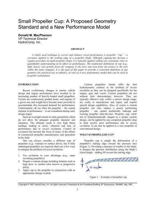
Small Propeller Cup: - Hydrocomp Inc.
Small Propeller Cup: - Hydrocomp Inc.
Small Propeller Cup: - Hydrocomp Inc.

You also want an ePaper? Increase the reach of your titles
YUMPU automatically turns print PDFs into web optimized ePapers that Google loves.
<strong>Small</strong> <strong>Propeller</strong> <strong>Cup</strong>: A Proposed Geometry<br />
Standard and a New Performance Model<br />
Donald M. MacPherson<br />
VP Technical Director<br />
HydroComp, <strong>Inc</strong>.<br />
ABSTRACT<br />
A widely used technique to correct and enhance vessel performance is propeller “cup” – a<br />
curvature applied to the trailing edge of a propeller blade. Although cupping has become a<br />
regular procedure in small propeller shops, it is typically applied without any systematic rules or<br />
quantifiable understanding of its effect on performance. The traditional definitions of cup (e.g.,<br />
light, heavy) vary greatly from one company to the next, and even from one project to the next<br />
within the same company. It is the goal of this paper to provide a consistent definition of cup<br />
geometry for practical use in industry, as well as a new performance model that can be used in<br />
propeller calculations.<br />
INTRODUCTION<br />
Recent evolutionary changes in marine vehicle<br />
design and engine performance have resulted in an<br />
increasing number of heavily-loaded small propellers.<br />
Vessels are continuously pushed faster, and engines of<br />
a given size and weight have become more powerful to<br />
accommodate this increased demand for performance.<br />
Unfortunately, all too often the propeller – the central<br />
element in performance – is not considered during early<br />
design stages.<br />
Such an oversight results in stern geometries which<br />
do not allow for adequate propeller diameter and<br />
clearance. The ultimate result is very high thrust<br />
loadings leading to noise, vibration and loss of<br />
performance due to excess cavitation. Control of<br />
cavitation has become the focus of many of the efforts<br />
of commercial propeller manufacturers and specialists<br />
in the field.<br />
One can always consider a different type of<br />
propulsor (e.g., waterjet or surface drive), but if fully<br />
submerged propellers are required, there are a few ways<br />
to mitigate the problem of excess cavitation:<br />
1. Use cavitation to your advantage (e.g., super<br />
cavitating propellers).<br />
2. Prepare a custom design including features such as<br />
high skew or camber (also known as progressive<br />
pitch).<br />
3. Apply cup to the propeller in conjunction with an<br />
appropriate change in pitch.<br />
Custom propellers clearly offer the best<br />
hydrodynamic solution to the problem of excess<br />
cavitation as they can be designed specifically for the<br />
engine, gear and vessel. Custom propellers are not<br />
without their shortcomings, however. They are<br />
typically effective only within a narrow design range,<br />
are costly to manufacture and repair, and require<br />
special design capabilities. Also, of course a custom<br />
propeller can only replace a poorly performing<br />
propeller – one cannot realistically redesign and<br />
existing propeller after-the-fact. <strong>Propeller</strong> cup, while<br />
not as hydrodynamically elegant as a proper custom<br />
design, can be applied by any competent propeller shop<br />
to help resolve poor performance due to excess<br />
cavitation. It can also be applied to a new propeller of<br />
conventional design.<br />
WHAT IS PROPELLER CUP?<br />
<strong>Propeller</strong> cup is simply the deformation of a<br />
propeller’s trailing edge toward the pressure face<br />
(Figure 1). Providing a measure of camber to the blade,<br />
it changes the pressure distribution along the blade’s<br />
chord length – adding lift toward the trailing edge.<br />
X<br />
30 deg<br />
Figure 1 – Example of propeller cup<br />
Copyright © 1997 HydroComp, <strong>Inc</strong>. All rights reserved. Presented at the <strong>Propeller</strong>s/Shafting '97 Symposium, SNAME, Sep 1997.<br />
1
How is this change in lift distribution useful in<br />
controlling cavitation? Typically you will find a peak in<br />
the lift distribution somewhere on the leading half of<br />
the blade. Cavitation occurs in this region when the<br />
local lift is greater than the vapor pressure of the water<br />
– causing it to vaporize or “boil”. (This vaporization<br />
creates the vapor “cavity” which gives cavitation its<br />
name.) Cavitation can be controlled if the peak lift can<br />
be reduced below the vapor pressure, while still<br />
generating the necessary total lift.<br />
Here is where cup comes in. By adding lift away<br />
from the peak via cupping, the entire lift can be reduced<br />
by a reduction in pitch. The more we need to reduce<br />
pitch to lower the peak lift, the more cup we need to<br />
add to compensate for the lost thrust. See Figure 2<br />
below for a descriptive comparison of this effect.<br />
Same suction/pressure area (lift) = same thrust<br />
Higher suction peak = more cavitation<br />
Higher pitch without cup<br />
Lower pitch with cup<br />
Lower suction peak = less cavitation<br />
Figure 2 – Performance comparison<br />
The history of propeller cupping is not clear, but has<br />
been in use for decades. Unlike progressive pitch<br />
propellers, cupping is not generally part of the original<br />
propeller design or manufacture. It is indeed an<br />
“aftermarket” performance boost applied in the best of<br />
propeller shop tradition – heat it and beat it. Of course,<br />
some shops are more elegant than others about the<br />
precision and tolerance of their application of cup.<br />
The lack of consistency in cup geometry is perhaps<br />
the greatest individual roadblock to a systematic<br />
understanding of the effect of cup on performance. No<br />
two organizations use the same definition of cup, and it<br />
is common to find differences in the application of cup<br />
even within the same shop. We can never develop a<br />
methodical understanding of the effects of cup without<br />
a consistent definition of the geometry.<br />
A PROPOSED STANDARD DEFINITION OF<br />
CUP GEOMETRY<br />
To most members of the general marine<br />
community, cup comes in two flavors – light and<br />
heavy. Unfortunately, one person’s light cup is another<br />
person’s heavy cup. These trailing edge deformations<br />
are very small – typically less than 10 mm (3/8 inch)<br />
for the heaviest of cups on most work boat and motor<br />
yacht propellers – so differences on such a small scale<br />
are easy to appreciate. It is also easy to see why a<br />
systematic definition of cup is so important.<br />
Some propeller manufacturers have proprietary<br />
systems of rating cup. <strong>Cup</strong> gauges classed as A, B, C,<br />
etc. document the amount of cup which was used and<br />
insure that a consistent cup is applied to all blades. Still,<br />
a quantifiable system is needed to determine<br />
performance changes.<br />
One systematic treatment of the shape and amount<br />
of cup was developed by the U.S. Navy’s small craft<br />
group (Hankley, 1983) (Denny, 1989). Hankley and<br />
Denny used the terms Light, Medium and Heavy to<br />
describe the extend of trailing edge drop based on the<br />
maximum thickness of the blade. These terms proved to<br />
be much more aggressive than commercial<br />
terminology. (These terms correlate well to a<br />
percentage of diameter for typical commercial<br />
propellers. The Light cup is typically about 0.5% of<br />
diameter, Medium is 1% and Heavy is 1.5%. Thus, the<br />
US Navy Heavy cup on a 36 inch propeller suggests<br />
more than one-half inch of deflection!) These terms are<br />
also subjective and are not “measurable”.<br />
This author proposes a standard definition loosely<br />
based on the Hankley/Denny definition described<br />
above. The goal is to remove any subjective terms like<br />
Heavy and Light. We propose that cup be defined by:<br />
1. The trailing edge drop in millimeters. (Dimension<br />
X in Figure 1.) For example, a propeller might<br />
have a 3 mm cup, another a 7 mm cup. No more<br />
Light and Heavy.<br />
2. <strong>Cup</strong> curvature is to be an arc with a radius 7.5<br />
times the drop, giving an extent of curvature of 30<br />
degrees.<br />
This now gives us a measurable definition with<br />
which we will build a performance model to determine<br />
how cup does affect thrust and torque.<br />
A NEW PROPELLER CUP PERFORMANCE<br />
MODEL<br />
Before considering a new model of cup<br />
performance, a review of current views is in order.<br />
Starting with the public at large, this author has<br />
2
witnessed a seriously misguided sense about cup. To<br />
quote a few published comments:<br />
• “cupping the prop acts like increased pitch<br />
(approximately 1 inch)”<br />
• “select blades with 1 inch or 5 percent less pitch<br />
than a similar uncupped blade”<br />
• “they serve no useful function on most vessels<br />
operating under 30 knots”<br />
• “add cup and your engine will lose about 200<br />
RPM”<br />
All of the above may be true for individual<br />
circumstances, but as universal statements of fact they<br />
fall short. These statements assume that all cupping is<br />
of the same size and has the same effect on all<br />
propellers. Of course, this is not the case. What is<br />
useful about the above statements is the notion of<br />
“effective” pitch.<br />
In other words, a propeller with cup acts as if it<br />
were a propeller with a somewhat higher pitch. (See<br />
Figure 2 where the cupped propeller of a lower pitch<br />
generates the same thrust as an uncupped propeller of a<br />
higher pitch.) The use of effective pitch makes a great<br />
deal of sense as it allows us to use conventional<br />
propeller performance curves for the analysis of cupped<br />
propellers.<br />
Rather than stating that “cup was worth one inch of<br />
pitch”, Denny offered a thoughtful analysis of effective<br />
pitch. For their Light, Medium and Heavy cups, the<br />
authors prepared a chart of effective pitch vs. geometric<br />
pitch, and Kt curves for a variety of 3-bladed Gawnstyle<br />
propellers. Unfortunately, no correlation for<br />
torque (Kq) was presented and the authors’ definition<br />
of geometric pitch included the cup deformation,<br />
making the correlation difficult to evaluate. This has<br />
lead this author and others in industry to the conclusion<br />
that the charts significantly over-estimate the effect of<br />
cup. (Full scale analysis of a number of motor yachts<br />
by this author also supports this conclusion.) Finally,<br />
three magnitudes of cup are inadequate to be useful to<br />
the industry at large. A finer distinction is required (i.e.,<br />
something less than Light and between Light and<br />
Medium).<br />
Hwang (Hwang, 1995) reached many of these<br />
same conclusions in their presentation of model tests<br />
and effective pitch for a 3-bladed Gawn-style propeller.<br />
They intentionally used a propeller geometry and<br />
Medium cup definition following that of Denny. The<br />
published results included both Kt and Kq curves over<br />
a range of P/D ratios, and show an increase in pitch to<br />
be significantly less than that of Denny.<br />
The following simple performance model attempts<br />
to eliminate the subjective terms of Light, Medium and<br />
Heavy, and follows the more modest pitch increases<br />
from Hwang and HydroComp sea trial data. Based on<br />
analysis of model test results and comparisons to full<br />
scale trial results, it was found that the value of the<br />
geometric pitch had little effect on the increase in pitch.<br />
Only the amount of cup deformation influenced the<br />
effective pitch.<br />
The new performance model is:<br />
P EFF = P GEO + 21(X CUP )<br />
where, P EFF = effective pitch<br />
P GEO = geometric (uncupped) face pitch<br />
X CUP = trailing edge deformation (drop)<br />
For example, the 250 mm propeller from Hwang<br />
had an average cup of 1.85 mm. The effective increase<br />
in pitch would then be approximately 39 mm. A<br />
summary of geometric pitch, calculated effective pitch<br />
(from the above relationship) and as-tested equivalent<br />
pitch (from corresponding Kt/Kq curves) is shown<br />
below.<br />
P GEO /D P GEO P EFF P EQUIV<br />
0.8 200 239 240 (0.96 P/D)<br />
1.0 250 289 285 (1.14 P/D)<br />
1.2 300 339 340 (1.36 P/D)<br />
1.4 350 389 390 (1.56 P/D)<br />
Table 1 – Corresponding effective pitch<br />
At no point was the calculated effective pitch more<br />
than 2% from the tested equivalent pitch, and there was<br />
very good correlation with both Kt and Kq. So, to find<br />
the necessary cup, first determine the pitch increase<br />
needed for performance and then divide the pitch<br />
increase by 21.<br />
There is one final point to remember when using<br />
this performance model. As you can see, effective pitch<br />
can increase substantially with cup. One must be sure to<br />
check that the effective pitch does not exceed the range<br />
of P/D ratio in the data set of the Kt/Kq formula. For<br />
example, the above propeller with a geometric pitch of<br />
400 (1.6 P/D) is within the upper limit of the Gawn-<br />
AEW equations (Blount, 1981), but the effective pitch<br />
of 439 mm (1.76 P/D) is outside of the range and the<br />
extrapolated results may be unreliable.<br />
Cavitation and effective pitch<br />
How is cavitation evaluated for a cupped<br />
propeller? The simple answer is that while performance<br />
corresponds to a propeller with a higher effective pitch,<br />
the levels of cavitation correspond to the geometric<br />
pitch of the propeller ahead of the cup.<br />
3
The traditional criteria for cavitation are all<br />
empirically-derived functions of blade pressure<br />
(MacPherson, 1991). They were developed over time to<br />
represent relationships between amounts of cavitation<br />
and “average” blade pressure for conventional<br />
(uncupped) propellers. To use these criteria with<br />
cupped propellers, it is necessary to calculate two<br />
different thrust values – a performance thrust at the<br />
effective pitch and then a theoretical “cavitation thrust”<br />
calculated at the geometric pitch. Average blade<br />
pressure, subsequent levels of cavitation and thrust loss<br />
are then derived from this “cavitation thrust”.<br />
MEASUREMENT OF CUP<br />
Knowing how much cup to apply is only half of<br />
the battle. The other half is actually getting the proper<br />
cup onto the propeller. Using the geometric definition<br />
of cup corresponding to Hankley and Denny, this<br />
author suggests the use of a propeller cup gauge similar<br />
to that shown in Figure 3.<br />
Each gauge is labeled for the amount of trailing<br />
edge deformation (drop) in millimeters (e.g., 5 mm). It<br />
would have a step of the proper dimension (e.g., 5 mm)<br />
to measure the drop, and a radius of 7.5 times the drop<br />
(e.g., 37.5 mm) to measure the curvature. Two marks of<br />
0 and 30 degrees would be scored on the radius to show<br />
the extent of curvature. A typical propeller shop would<br />
have gauges in 1 mm increments up to 10 mm or so.<br />
5.0<br />
25.0 25.00<br />
HydroComp<br />
5mm <strong>Cup</strong> Gauge<br />
0<br />
30<br />
R37.5<br />
90.0<br />
(90%R), with a smooth transition to no cup at both<br />
extents. (One note of interest: a few companies have<br />
had some success in varying the cup distribution,<br />
typically with greater cup near the tip, in an attempt to<br />
fine-tune performance at various speeds.)<br />
CONCLUSION<br />
The simple geometric definition and performance<br />
model described above are intended to bring some<br />
sense of consistency to the community of propeller<br />
manufacturers, after-market propeller shops, naval<br />
architects and other marine professionals interested in<br />
cupped propeller performance. An earlier generation of<br />
the performance model implemented in a commercial<br />
software package (HydroComp, 1996) has been used<br />
successfully by dozens of marine professionals for<br />
numerous new and repowered vessels.<br />
Work is continuing to improve the performance<br />
model by segregating thrust and torque, by evaluating<br />
the effect of other propeller parameters (e.g., mean<br />
width ratio) and by refining the relationship with new<br />
data from model tests and sea trials, particularly for 4-<br />
and 5-bladed propellers of very high blade area.<br />
REFERENCES<br />
Blount, D.L. and Hubble, E.N., “Sizing Segmental<br />
Section Commercially Available <strong>Propeller</strong>s for <strong>Small</strong><br />
Craft”, SNAME <strong>Propeller</strong> Symposium, 1981.<br />
Denny, S.B., Puckette, L.T., Hubble, E.N., Smith, S.K.<br />
and Najarian, R.F., “A New Usable <strong>Propeller</strong> Series”,<br />
Marine Technology, Vol. 26, No. 3, July 1989.<br />
Hwang JL, Tsai JF and Li CY, “<strong>Cup</strong>ped <strong>Propeller</strong> Test<br />
and Analysis”, Ship Technology Research, Vol. 32,<br />
1995.<br />
Hankley, D.W. and Denny, S.B., “Performance<br />
Characteristics for a Series of Commercially Available<br />
<strong>Propeller</strong>s for <strong>Small</strong> Craft”, SNAME, San Diego<br />
Section, Feb 1983.<br />
87.5<br />
Figure 3 – <strong>Cup</strong> gauge<br />
Consistency of pitch and cup is very important, so<br />
industry practice is to apply the same amount of cup<br />
across the blade. Typically, the required cup would be<br />
fit from the mid-radius (40%-50%R) to near the tip<br />
HydroComp, <strong>Inc</strong>., HydroComp PropExpert program<br />
and documentation, 1996.<br />
MacPherson, D.M., “Reliable <strong>Propeller</strong> Selection for<br />
Work Boats and Pleasure Craft: Techniques Using a<br />
Personal Computer”, SNAME Power Boat Symposium,<br />
1991.<br />
4
DISCUSSION<br />
Dudley Dawson, P.E., Member<br />
I’d like to thank the author for this significant<br />
contribution to the field of small craft propeller<br />
technology. As a designer specializing in power vessels<br />
up to about 60 meters in length, I am well aware of the<br />
current uncertainties and problems in specifying<br />
propellers with an unquantified light, medium or heavy<br />
cup. The proposed measurement system will address<br />
these problems, but only if propeller manufacturers and<br />
distributors put into place a system of implementing<br />
and verifying cup dimensions. It is up to naval<br />
architects and marine engineers to use the system<br />
regularly in their specifications and insist that suppliers<br />
adhere to it. Once it has been given a fair trial and any<br />
bugs worked out of the system, then an ABYC or SAE<br />
standard formalizing the measurement system would be<br />
in order.<br />
In addition to those cited in the paper, there are<br />
several other reasons that the specification of cup may<br />
be desirable. One of the unfortunate trends in modern<br />
power vessel design and construction is a general<br />
increase in both weight and power for a vessel of given<br />
physical dimensions. While weight and power have<br />
increased, indicating additional propeller blade area,<br />
the depth of water has not increased in the Caribbean<br />
for yachts nor in the Gulf of Mexico for crewboats nor<br />
in rivers for workboats and ferries. Some commercial<br />
vessels have addressed this problem by installing<br />
additional propellers (4 or more) of the same limited<br />
diameter. Although there are a few yachts with 3<br />
engines and propellers, most have been limited to 2<br />
engines and propellers by owner demands. For this<br />
market, the use of hull-bottom propeller tunnels with<br />
larger diameter, high-area ratio propellers is finding<br />
increased acceptance (Dawson, 1997). In many cases,<br />
this is sufficient to provide the necessary propeller<br />
blade area without increased draft but in some extreme<br />
cases, the specification of cup in a new installation is<br />
necessary to avoid or abate cavitation that cannot be<br />
designed out by other means.<br />
There are also sound economic reasons for<br />
specifying cup in a new installation. It is generally<br />
much less expensive to include cup in a manufacturer’s<br />
stock propeller than to specify a custom propeller with<br />
cambered and skewed blade patterns. Often, the<br />
theoretical difference in performance is quite small, and<br />
in full-scale tests, unmeasurable. Also, one of the most<br />
common uncertainties between the preliminary design<br />
and complete vessel stages is the full-load displacement<br />
of the vessel as built, and it is for this condition that<br />
most propellers should be specified. By specifying a<br />
propeller that is slightly underpitched, but provided<br />
with moderate cup, the problems of under- or overdisplacement<br />
(cavitation, inability to attain full engine<br />
RPM, inability to attain full power loading or speed)<br />
can often be addressed by adjustments in cup rather<br />
than having to repitch the propellers.<br />
Although both the title and the text of the paper<br />
indicate that the proposed measurement system and<br />
effective pitch methodology are for small craft and<br />
small propellers, no quantification of “small” is given.<br />
It would be of benefit if the author could indicate<br />
recommended lower and upper limits based on the trial<br />
data used and his verification of the methodology.<br />
Finally, there is one item of practical concern. The<br />
author proposes that the radius of the cup vary directly<br />
as a percentage of the drop (or deflection), resulting in<br />
a discrete radius for each value of drop, and larger radii<br />
for larger drops (heavier cups). Many of the propeller<br />
shops working on small propellers are indeed of the<br />
“heat it and beat it” variety with a minimal investment<br />
in equipment. Often, current practice is for a piece of<br />
round steel bar stock to be used as a rough mandrel to<br />
cup the trailing edge, and light vs. heavy cup is thus a<br />
matter of varying the extent rather than the radius of the<br />
curved portion. Also, when an existing heavy cup is<br />
modified to a light cup, it is often done by bending the<br />
trailing edge back toward the flat, so a lighter cup may<br />
end up with more radius than a heavy one. The author’s<br />
comments on technical considerations of the two<br />
differing systems would be appreciated, along with his<br />
thoughts on whether it would be possible to use a<br />
discrete number of mandrel radii (say, 2 or 3) to cover<br />
the range from 1 to 10 millimeters of cup without<br />
significant loss of effectiveness.<br />
Additional reference<br />
Dawson, D.A., “Faster, Farther, and More Fuel-<br />
Efficient”, Professional BoatBuilder, No. 44,<br />
December/January 1997.<br />
Author’s Closure<br />
Many thanks to Mr. Dawson for his real-world<br />
perspective on the use of cupped propellers. They are a<br />
valuable addition to the paper.<br />
Regarding acceptance of the measurement system<br />
by some regulating body (e.g., ABYC, SAE), any<br />
system will have to stand on its own merits – and this<br />
proposed system is no exception. It is my hope that this<br />
5
will not be the industry’s final effort on this topic, but<br />
will lead to additional interest, research and practical<br />
development.<br />
The term “small” is meant nothing more than to<br />
provide some scope for the topic. As the fundamental<br />
research was conducted and trial data evaluated on<br />
propellers germane to small vessels (i.e., diameters<br />
under about 32”), the model should not be extrapolated<br />
to large propellers. Fortunately since cupping is<br />
typically a “small” propeller practice, extrapolation to<br />
larger diameters is moot.<br />
Using a smaller mandrel to extend the cup onto the<br />
blade so as to create an “effective” radius of cup would<br />
depend on the skill of the craftsman, I suppose.<br />
Unfortunately, I have no data to support or dismiss this<br />
from a performance standpoint. I would not endorse<br />
altering the proposed geometry, however, simply<br />
because it is the way that things are done today.<br />
<strong>Cup</strong>ping is indeed a “performance tweak”, and it is not<br />
unreasonable to suggest that if propeller builders and<br />
vendors want to develop this expertise, then they<br />
should have the proper tools – just as they do now with<br />
a range of proper pitch blocks or even digital<br />
measurement devices, for example.<br />
My thanks again to Dudley Dawson for his<br />
comments and to Peter Lapp of the Bird-Johnson<br />
Company for this technical review.<br />
6