133 - Hydrocomp Inc.
133 - Hydrocomp Inc.
133 - Hydrocomp Inc.

You also want an ePaper? Increase the reach of your titles
YUMPU automatically turns print PDFs into web optimized ePapers that Google loves.
IDF Hull Data Transfer Format<br />
A HydroComp Technical Report<br />
Report <strong>133</strong><br />
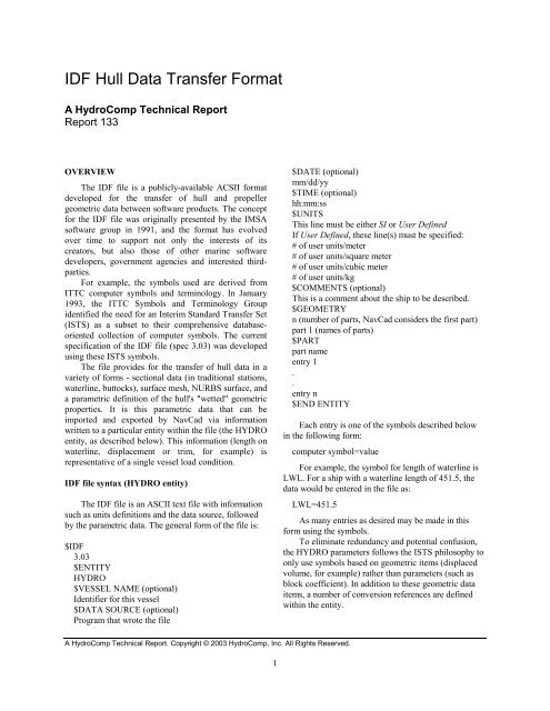
OVERVIEW<br />
The IDF file is a publicly-available ACSII format<br />
developed for the transfer of hull and propeller<br />
geometric data between software products. The concept<br />
for the IDF file was originally presented by the IMSA<br />
software group in 1991, and the format has evolved<br />
over time to support not only the interests of its<br />
creators, but also those of other marine software<br />
developers, government agencies and interested thirdparties.<br />
For example, the symbols used are derived from<br />
ITTC computer symbols and terminology. In January<br />
1993, the ITTC Symbols and Terminology Group<br />
identified the need for an Interim Standard Transfer Set<br />
(ISTS) as a subset to their comprehensive databaseoriented<br />
collection of computer symbols. The current<br />
specification of the IDF file (spec 3.03) was developed<br />
using these ISTS symbols.<br />
The file provides for the transfer of hull data in a<br />
variety of forms - sectional data (in traditional stations,<br />
waterline, buttocks), surface mesh, NURBS surface, and<br />
a parametric definition of the hull's "wetted" geometric<br />
properties. It is this parametric data that can be<br />
imported and exported by NavCad via information<br />
written to a particular entity within the file (the HYDRO<br />
entity, as described below). This information (length on<br />
waterline, displacement or trim, for example) is<br />
representative of a single vessel load condition.<br />
IDF file syntax (HYDRO entity)<br />
The IDF file is an ASCII text file with information<br />
such as units definitions and the data source, followed<br />
by the parametric data. The general form of the file is:<br />
$IDF<br />
3.03<br />
$ENTITY<br />
HYDRO<br />
$VESSEL NAME (optional)<br />
Identifier for this vessel<br />
$DATA SOURCE (optional)<br />
Program that wrote the file<br />
$DATE (optional)<br />
mm/dd/yy<br />
$TIME (optional)<br />
hh:mm:ss<br />
$UNITS<br />
This line must be either SI or User Defined<br />
If User Defined, these line(s) must be specified:<br />
# of user units/meter<br />
# of user units/square meter<br />
# of user units/cubic meter<br />
# of user units/kg<br />
$COMMENTS (optional)<br />
This is a comment about the ship to be described.<br />
$GEOMETRY<br />
n (number of parts, NavCad considers the first part)<br />
part 1 (names of parts)<br />
$PART<br />
part name<br />
entry 1<br />
.<br />
.<br />
entry n<br />
$END ENTITY<br />
Each entry is one of the symbols described below<br />
in the following form:<br />
computer symbol=value<br />
For example, the symbol for length of waterline is<br />
LWL. For a ship with a waterline length of 451.5, the<br />
data would be entered in the file as:<br />
LWL=451.5<br />
A HydroComp Technical Report. Copyright © 2003 HydroComp, <strong>Inc</strong>. All Rights Reserved.<br />
1<br />
As many entries as desired may be made in this<br />
form using the symbols.<br />
To eliminate redundancy and potential confusion,<br />
the HYDRO parameters follows the ISTS philosophy to<br />
only use symbols based on geometric items (displaced<br />
volume, for example) rather than parameters (such as<br />
block coefficient). In addition to these geometric data<br />
items, a number of conversion references are defined<br />
within the entity.
Abbreviations used in the format description below<br />
are:<br />
FP - forward perpendicular. This is a reference datum<br />
for the forward point of the length between<br />
perpendiculars (LPP).<br />
AP - after perpendiculars. This is a reference datum for<br />
the aft point of the length between perpendiculars<br />
(LPP).<br />
MIDP - midship. This is located midway between FP<br />
and AP.<br />
SYMBOLS<br />
Symbol Units Description<br />
Standard reference definitions used by the HYDRO<br />
entity of the IDF are:<br />
International nautical mile - 6076.1155 feet, 1852.00<br />
meters.<br />
Gravitational constant - G 32.174 ft/s 2 , 9.80665 m/s 2 .<br />
ABT Area Total area of transverse cross-section of bulbous bow. Full (port and starboard) cross sectional<br />
area at the FP.<br />
AM Area Midship section area. Immersed transverse sectional area located at MIDP.<br />
APB Area Planing bottom area. Horizontally projected planing bottom area (at rest), excluding area of<br />
external spray strips. (Area outlined by the chine as projected onto a horizontal plane.)<br />
ATR Area Total area of immersed transom. Full (port and starboard) cross-sectional area of a transom stern<br />
below the waterline.<br />
AVL Area Longitudinal area exposed to wind. Area of portion of ship above waterline projected onto a<br />
longitudinal plane (as viewed from the side).<br />
AVT Area Transverse area exposed to wind. Area of portion of ship above waterline projected onto a<br />
transverse plane (as viewed from ahead).<br />
AW Area Area of the waterplane. Area enclosed by the outline of the waterplane.<br />
AX Area Maximum immersed transverse sectional area.<br />
BETD Deg Principal deadrise angle of planing bottom. Angle of the tangent slope of the planing bottom. (For<br />
a temporary solution, the tangent slope of the planing bottom at a point BPX/4 off the centerline,<br />
located at the mid-point of LPRC, is recommended).<br />
BETTR Deg Deadrise angle of planing bottom at transom. Angle of the tangent slope of the planing bottom at<br />
the transom, (For a temporary solution, the tangent slope of the planing bottom at a point BTR/4<br />
off the centerline, located at the aftmost point of LPRC, is recommended).<br />
BM Length Midship breadth on waterline. Molded breadth on the waterline located at MIDP.<br />
BPX Length Maximum breadth over chines. Maximum breadth of the outside of the chine (excluding external<br />
spray strips).<br />
BTR Length Breadth of the chine at the transom. Breadth of the outside of the chine (excluding external spray<br />
strips) at the transom (the aftmost point of LPRC).<br />
2
BX Length Maximum breadth on waterline.<br />
DISV Vol Displacement volume. Immersed volume of the hull, neglecting appendages. (Large added<br />
volumes, such as skegs may have a contribution to hull volume, so there should be data agreement<br />
between SWH and DISV.)<br />
ENTA Deg Half angle of entrance. Angle of waterline at the bow with reference to centerplane, neglecting<br />
local shape at stem. (For a temporary solution, the tangent slope of the waterplane at a point BX/10<br />
off the centerline is recommended.)<br />
LOS Length Overall submerged length. Entire length of the submerged portion of the vessel, including items<br />
such as bulbs that extend beyond the limits of LWL.<br />
LPP Length Length between perpendiculars. Reference length that defines the distance between FP and AP.<br />
LPRC Length Projected chine length. Overall longitudinal length of chine projected onto a horizontal plane.<br />
(Longitudinal limit of APB.)<br />
LWL Length Length of waterline. Overall longitudinal length of the waterplane.<br />
RHOW Mass<br />
Vol<br />
Mass density of water in the form of Mass / Vol. You must insure that Mass and Volume units<br />
conversions from the $UNITS section are applied properly.<br />
Standard ITTC values at 15degC/59degF are:<br />
Fresh 999.01 kg/m 3 ; 1.9384 slug/ft 3 (lbf-s 2 /ft 4 ); specific grav 0.9990<br />
Salt 1025.86 kg/m 3 ; 1.9905 slug/ft 3 (lbf-s 2 /ft 4 ); specific grav 1.0259<br />
NOTE: Specific gravity uses the international convention of distilled water at 3.98degC (999.97<br />
kg/m 3 , 1.9403 slug/ft 3 ).<br />
SWH Area Wetted surface of the hull. Entire immersed surface of the hull, neglecting appendages. (Large<br />
added volumes, such as skegs may have a contribution to hull volume, so there should be data<br />
agreement between SWH and DISV.)<br />
TM Length Draft at midship. Molded hull draft on centerline, located at MIDP. Value reflects the principal<br />
hull volume and should not be confused with a keel draft that includes the effect of appendages or<br />
skegs.<br />
TR Length Trim. Vessel trim by the stern. Equals the draft at AP less the draft at FP.<br />
XFB Length Longitudinal center of buoyancy from FP. Longitudinal distance of the center of buoyancy aft of<br />
FP.<br />
XFG Length Longitudinal center of gravity from FP. Longitudinal distance of the center of gravity aft of FP.<br />
XLWL Length Location of length on waterline. Distance of the forward-most point of LWL aft of FP. (Registers<br />
location of LWL with respect to FP.)<br />
XLPRC Length Location of projected chine length. Distance of the forward-most point of LPRC aft of FP.<br />
(Registers location of LPRC with respect to FP.)<br />
SAMPLE FILE<br />
The following is a sample of an IDF file for a Series 60 cargo ship, as exported from NavCad. The data is in<br />
units of Feet and Long Tons, so the appropriate User Defined units conversions are included. There is a single "part"<br />
3
and it is given the name "MAINHULL". The file includes data for midship and waterplane areas, beam, displaced<br />
volume, half angle of entrance, lengths, mass density of the condition, wetted surface, draft and LCB. (The<br />
indentation shown is optionally included in the exported file simply to make it easier for someone to read.)<br />
$IDF<br />
3.03<br />
$ENTITY<br />
HYDRO<br />
$DATA SOURCE<br />
HydroComp NavCad 4.20<br />
$DATA<br />
05/10/02<br />
$TIME<br />
10:02:12<br />
$UNITS<br />
User Defined<br />
3.280839895<br />
10.7639104167<br />
35.3146667215<br />
.0009842065<br />
$GEOMETRY<br />
1<br />
$PART<br />
MAINHULL<br />
AM=1513.5<br />
AW=21127.3866<br />
AX=1513.5<br />
BX=62.07<br />
DISV=450851.003705525<br />
ENTA=12.9<br />
LOS=457.5<br />
LPP=450<br />
LWL=457.5<br />
RHOW=.028590376630101<br />
SWH=37230<br />
TM=24.83<br />
XFB=231.93<br />
$END ENTITY<br />
4<br />
HydroComp, <strong>Inc</strong>.<br />
13 Jenkins Court, Suite 200<br />
Durham, NH 03824 USA<br />
Tel (603)868-3344<br />
Fax (603)868-3366<br />
info@hydrocompinc.com<br />
www.hydrocompinc.com