EM24 DIN DS ENG 121107.pdf - UK Metering
EM24 DIN DS ENG 121107.pdf - UK Metering
EM24 DIN DS ENG 121107.pdf - UK Metering

You also want an ePaper? Increase the reach of your titles
YUMPU automatically turns print PDFs into web optimized ePapers that Google loves.
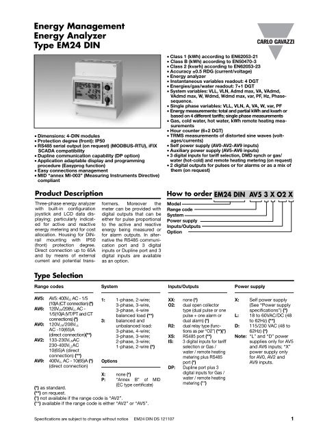
Energy Management<br />
Energy Analyzer<br />
Type <strong>EM24</strong> <strong>DIN</strong><br />
• Dimensions: 4-<strong>DIN</strong> modules<br />
• Protection degree (front): IP50<br />
• RS485 serial output (on request) (MODBUS-RTU), iFIX<br />
SCADA compatibility<br />
• Dupline communication capability (DP option)<br />
• Application adaptable display and programming<br />
procedure (Easyprog function)<br />
• Easy connections management<br />
• MID “annex MI-003” (Measuring Instruments Directive)<br />
compliant<br />
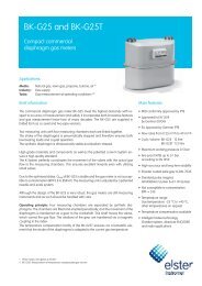
Product Description<br />
Three-phase energy analyzer<br />
with built-in configuration<br />
joystick and LCD data displaying;<br />
particularly indicated<br />
for active and reactive<br />
energy metering and for cost<br />
allocation. Housing for <strong>DIN</strong>rail<br />
mounting with IP50<br />
(front) protection degree.<br />
Direct connection up to 65A<br />
and by means of external<br />
current and potential trans-<br />
formers. Moreover the<br />
meter can be provided with<br />
digital outputs that can be<br />
either for pulse proportional<br />
to the active and reactive<br />
energy being measured or<br />
for alarm outputs. In alternative<br />
the RS485 communication<br />
port and 3 digital<br />
inputs or Dupline port and 3<br />
digital inputs are available<br />
as an option.<br />
• Class 1 (kWh) according to EN62053-21<br />
• Class B (kWh) according to EN50470-3<br />
• Class 2 (kvarh) according to EN62053-23<br />
• Accuracy ±0.5 RDG (current/voltage)<br />
• Energy analyzer<br />
• Instantaneous variables readout: 4 DGT<br />
• Energies/gas/water readout: 7+1 DGT<br />
• System variables: VLL, VLN, Admd max, VA, VAdmd,<br />
VAdmd max, W, Wdmd, Wdmd max, var, PF, Hz, Phasesequence.<br />
• Single phase variables: VLL, VLN, A, VA, W, var, PF<br />
• Energy measurements: total and partial kWh and kvarh or<br />
based on 4 different tariffs; single phase measurements<br />
• Gas, cold water, hot water, kWh remote heating measurements<br />
• Hour counter (6+2 DGT)<br />
• TRMS measurements of distorted sine waves (voltages/currents)<br />
• Self power supply (AV0-AV2-AV9 inputs)<br />
• Auxiliary power supply (AV5-AV6 inputs)<br />
• 3 digital inputs for tariff selection, DMD synch or gas/<br />
water (hot-cold) and remote heating metering (on request)<br />
• 2 digital outputs for pulses or for alarms or as a mix of<br />
them (on request)<br />
How to order <strong>EM24</strong> <strong>DIN</strong> AV5 3 X O2 X<br />
Model<br />
Range code<br />
System<br />
Power supply<br />
Inputs/Outputs<br />
Option<br />
Type Selection<br />
Range codes<br />
System<br />
Inputs/Outputs<br />
Power supply<br />
AV5: AV5: 400V LL AC - 1/5<br />
(10)A (CT connection) (*)<br />
AV6: 120V LN/208V LL AC -<br />
1/5(10)A (VT/PT and CT<br />
connections) (*)<br />
AV0: 120V LN/208V LL<br />
AC -10(65)A<br />
AV2:<br />
(direct connection)(**)<br />
133-230V LNAC<br />
230-400V LLAC<br />
10(65)A (direct<br />
connection) (**)<br />
AV9: 400V LL AC - 10(65)A (*)<br />
(direct connection)<br />
1: 1-phase, 2-wire;<br />
3-phase, 3-wire,<br />
3-phase, 4-wire<br />
balanced load (**)<br />
3: balanced and<br />
unbalanced load:<br />
3-phase, 4-wire;<br />
3-phase, 3-wire;<br />
2-phase, 3-wire;<br />
1-phase, 2-wire (*)<br />
Options<br />
X: none (*)<br />
P: “Annex B” of MID<br />
(*) as standard.<br />
(EC type certificate)<br />
(**) on request.<br />
(°) not available if the range code is “AV2”.<br />
(°°) available if the range code is either “AV2” or “AV5”.<br />
XX: none (*)<br />
O2: dual open collector<br />
type (dual pulse or one<br />
pulse + one alarm or<br />
dual alarm) (*)<br />
R2: dual relay type (functions<br />
as per “O2”) (**)(°)<br />
XS: RS485 port (**)<br />
IS:<br />
3 digital inputs for tariff<br />
selection or Gas /<br />
water / remote heating<br />
metering plus RS485<br />
port (*)<br />
DP: Dupline port plus 3<br />
digital inputs for Gas /<br />
water / remote heating<br />
metering (°°)<br />
X: Self power supply<br />
(See “Power supply<br />
specifications”) (*)<br />
L: 18 to 60VAC/DC (48<br />
to 62Hz) (**)<br />
D: 115/230 VAC (48 to<br />
62Hz) (*)<br />
Note: “L” and “D” power<br />
supplies only for AV5<br />
and AV6 inputs; “X”<br />
power supply only<br />
for AV0, AV2 and<br />
AV9 inputs.<br />
Specifications are subject to change without notice <strong>EM24</strong> <strong>DIN</strong> <strong>DS</strong> 121107 1
<strong>EM24</strong> <strong>DIN</strong><br />
Input specifications<br />
Rated inputs<br />
System type: 3-phase<br />
Current type<br />
Galvanic insulation by means<br />
of built-in CT’s (AV5 and AV6<br />
models). By direct connection<br />
(AV0, AV2 and AV9)<br />
Current range (by CT) AV5 and AV6: 1/5(10)A<br />
Current range (direct) AV0: 10(65)A; AV2: 10(65)A;<br />
AV9: 10(65)A<br />
Voltage<br />
AV5: 400 VLL<br />
Voltage<br />
AV0: 120VLN/208 VLL<br />
AV2: 230/400 VLL<br />
AV9: 400 VLL<br />
Voltage by VT/PT<br />
AV6: 120VLN/208 VLL<br />
Accuracy (Display + RS485) Ib: see below, Un: see below<br />
(@25°C ±5°C, R.H. ≤60%, 48 to 62Hz)<br />
AV5 model In: 5A, Imax: 10A; Un: 160<br />
to 480VLN (277 to 830VLL)<br />
AV6 model<br />
In: 5A, Imax: 10A; Un: 40 to<br />
144VLN (70 to 250VLL)<br />
AV0 model Ib: 10A, Imax: 65A; Un: 96<br />
to 144VLN (166 to 250VLL)<br />
AV2 model Ib: 10A, Imax: 65A, Un: 113<br />
to 265VLN (196 to 460VLL)<br />
AV9 model Ib: 10A, Imax: 65A; Un: 184<br />
to 276VLN (318 to 480VLL)<br />
Current<br />
AV5, AV6 models<br />
AV0, AV2, AV9 models<br />
From 0.002In to 0.2In:<br />
±(0.5% RDG +3DGT)<br />
From 0.2In to Imax:<br />
±(0.5% RDG +1DGT).<br />
From 0.004Ib to 0.2Ib:<br />
±(0.5% RDG +3DGT)<br />
From 0.2Ib to Imax:<br />
±(0.5% RDG +1DGT).<br />
Phase-neutral voltage In the range Un: ±(0,5%<br />
RDG +1DGT)<br />
Phase-phase voltage In the range Un: ±(1% RDG<br />
+1DGT)<br />
Frequency<br />
±0.1Hz (45 to 65Hz)<br />
Active and Apparent power ±(1%RDG +2DGT)<br />
Power Factor<br />
±[0.001+1%(1.000 - “PF<br />
RDG”)]<br />
Reactive power<br />
±(2%RDG +2DGT)<br />
Active energy<br />
Class 1 according to<br />
EN62053-21 and MID<br />
Annex MI-003 Class B<br />
according to EN50470-3<br />
Reactive energy<br />
Class 2 according to<br />
EN62053-23<br />
AV5, AV6 models In: 5A, Imax: 10A;<br />
0.1 In: 0.5A,<br />
Start up current: 10mA<br />
AV0, AV2, AV9 models Ib: 10A, Imax: 65A;<br />
0.1 Ib: 1.0A<br />
Start up current: 40mA<br />
Energy additional errors<br />
Influence quantities<br />
According to EN62053-21,<br />
Temperature drift<br />
Sampling rate<br />
Display refresh time<br />
Display<br />
EN50470-3, EN62053-23<br />
≤200ppm/°C<br />
1600 samples/s @ 50Hz<br />
1900 samples/s @ 60Hz<br />
750 ms<br />
3 lines (1 x 8 DGT; 2 x 4 DGT)<br />
Type<br />
Instantaneous variables read-out<br />
Energies<br />
Overload status<br />
Max. and Min. indication<br />
LEDs<br />
AV5, AV6 models<br />
AV0, AV2, AV9 models<br />
Max frequency<br />
Measurements<br />
Method<br />
Coupling type<br />
Crest factor<br />
Current Overloads<br />
Continuous<br />
For 500ms<br />
For 10ms<br />
Voltage Overloads<br />
Continuous<br />
For 500ms<br />
Input impedance<br />
208VL-L (AV6)<br />
208VL-L (AV0)<br />
230/400VL-L (AV2)<br />
400VL-L (AV5)<br />
400VL-L (AV9)<br />
1/5(10)A (AV5-AV6)<br />
10(65)A (AV0-AV2-AV9)<br />
Frequency<br />
Joystick<br />
LCD, h 7mm<br />
4 DGT<br />
Imported Total/Partial/<br />
Tariff: 7+1DGT or 8DGT;<br />
Exported Total/Partial/<br />
Tariff: 6+1DGT or 7DGT<br />
(with “-“ sign)<br />
EEEE indication when the<br />
value being measured is<br />
exceeding the “Continuous<br />
inputs overload” (maximum<br />
measurement capacity)<br />
Max. instantaneous variables:<br />
9999; energies:<br />
9 999 999.9 or 99 999999.<br />
Min. instantaneous variables:<br />
0.000; energies 0.0<br />
Red LED (Energy consumption)<br />
0.001 kWh/kvarh by pulse if<br />
CT ratio by VT ratio is ≤7;<br />
0.01 kWh/kvarh by pulse if CT<br />
ratio x VT ratio is > 7.1 ≤ 70.0;<br />
0.1 kWh/kvarh pulse if CT ratio<br />
x VT ratio is > 70.1 ≤ 700.0;<br />
1 kWh/kvarh by pulse if CT<br />
ratio x VT ratio is > 700.1;<br />
0.001kWh/kvarh by pulse<br />
16Hz, according to<br />
EN50470-3<br />
See “List of the variables<br />
that can be connected to:”<br />
TRMS measurements of<br />
distorted wave forms.<br />
Direct for AV0, AV2 and AV9<br />
models. By means of external<br />
CT’s for AV5 and AV6<br />
Ib 10A ≤4 (91A max. peak)<br />
In 5A ≤3 (15A max. peak)<br />
1/5(10) A: 10A, @ 50Hz<br />
10(65) A: 65A, @ 50Hz<br />
1/5(10) A: 200A, @ 50Hz<br />
10(65) A: 1920A max, @ 50Hz<br />
1.2 Un<br />
2 Un<br />
>1600KΩ<br />
Refer to “Power Consumption”<br />
Refer to “Power Consumption”<br />
>1600KΩ<br />
Refer to “Power Consumption”<br />
< 0.3VA<br />
< 4VA<br />
45 to 65 Hz<br />
For variable selection and<br />
programming of the instrument<br />
working parameters<br />
2 Specifications are subject to change without notice <strong>EM24</strong> <strong>DIN</strong> <strong>DS</strong> 121107
<strong>EM24</strong> <strong>DIN</strong><br />
Output specifications<br />
Digital outputs<br />
Pulse type<br />
Number of outputs<br />
Type<br />
Pulse duration<br />
Alarm type<br />
Number of outputs<br />
Alarm modes<br />
Set-point adjustment<br />
Hysteresis<br />
On-time delay<br />
Output status<br />
Min. response time<br />
Note<br />
Static output<br />
Purpose<br />
Signal<br />
Insulation<br />
Relay output<br />
Purpose<br />
Type<br />
Insulation<br />
Up to 2, independent.<br />
Programmable from 0.001<br />
to 10.00kWh/kvarh by<br />
pulse.<br />
Outputs connectable to the<br />
energy meters (kWh/kvarh)<br />
≥100ms < 120msec (ON),<br />
≥120ms (OFF), according<br />
to EN62053-31<br />
Up to 2, independent<br />
Up alarm, down alarm (see<br />
the table “List of the<br />
variables that can be<br />
connected to”)<br />
From 0 to 100% of the display<br />
scale<br />
From 0 to full scale<br />
0 to 255s<br />
Selectable; normally<br />
de-energized or normally<br />
energized<br />
≤ 700ms, filter excluded,<br />
set-point on-time delay: “0 s”<br />
The 2 digital outputs can<br />
also work as a dual pulse<br />
output, dual alarm output,<br />
one pulse output and one<br />
alarm output.<br />
For pulse output or alarm<br />
output<br />
V ON 1.2 VDC/ max. 100 mA<br />
V OFF 30 VDC max.<br />
By means of optocuplers,<br />
4000 VRMS output to<br />
measuring inputs,<br />
4000 VRMS output to<br />
power supply input.<br />
For alarm output or pulse<br />
output<br />
Relay, SPST type<br />
AC 1-5A @ 250VAC<br />
DC 12-5A @ 24VDC<br />
AC 15-1.5A @ 250VAC<br />
DC 13-1.5A @ 24VDC<br />
4000 VRMS output to<br />
measuring input<br />
4000 VRMS output to<br />
power supply input.<br />
Note<br />
RS485<br />
Type<br />
Connections<br />
Addresses<br />
Protocol<br />
Data (bidirectional)<br />
Dynamic (reading only)<br />
Static (reading and writing)<br />
Data format<br />
Baud-rate<br />
Driver input impedance<br />
Insulation<br />
Note:<br />
The meters equipped with<br />
the relay outputs (“AV0”<br />
and “AV9” models with<br />
“R2” option) work even if<br />
VL3 is missing (VL1, VL2<br />
and neutral have to be<br />
available)(see table “working<br />
mode notes”)<br />
Multidrop, bidirectional<br />
(static and dynamic variables)<br />
2-wire<br />
Max. distance 1000m<br />
247, selectable by means<br />
of the front joystick<br />
MODBUS/JBUS (RTU)<br />
System and phase variables:<br />
see table “List of<br />
variables...”<br />
All the configuration<br />
parameters.<br />
1 start bit, 8 data bit, no<br />
parity,1 stop bit<br />
4800, 9600 bit/s<br />
1/5 unit load<br />
Maximum 160 transceivers<br />
on the same bus.<br />
By means of optocouplers,<br />
4000 VRMS output to<br />
measuring input,<br />
4000 VRMS output to<br />
power supply input.<br />
The meters equipped with<br />
the communication port<br />
(“AV0” and “AV9” models<br />
with “XS” and “IS” options)<br />
work even if VL3 is missing<br />
(VL1, VL2 and neutral have<br />
to be available)(see table<br />
“working mode notes”)<br />
Specifications are subject to change without notice <strong>EM24</strong> <strong>DIN</strong> <strong>DS</strong> 121107 3
<strong>EM24</strong> <strong>DIN</strong><br />
Dupline specifications<br />
Counters<br />
Used Dupline function Multiplexer for counter values<br />
Number of counters<br />
6 per instrument<br />
128 per network<br />
Counter range 0... 99 999 999<br />
Used channels<br />
B to F<br />
Multiplexer<br />
B2 to B8<br />
Reset<br />
B1<br />
Value<br />
C1 to F8<br />
Counter reset<br />
Enable/disable function for<br />
all the counters<br />
Available counters<br />
kWh tot, -kWh tot,<br />
kvarh tot, -kvarh tot,<br />
kWh t1, kWh t2,<br />
kWh L1, kWh L2, kWh L3,<br />
counter dig. in. 1,<br />
counter dig. in. 2,<br />
counter dig. in. 3,<br />
hour counter.<br />
Analogue variables<br />
Used Dupline function Multiplexer for analogue<br />
values<br />
Number of variables<br />
8 per instrument<br />
80 per network<br />
Dupline data format<br />
3 1/2 DGT BCD<br />
Full scale value<br />
Selectable from 1.999 to<br />
1999M<br />
Used channels<br />
depending on the number<br />
of variables<br />
Multiplexer<br />
A1 to A4<br />
Value G1 to H8 (1 st group of 16<br />
variables)<br />
I1 to J8 (2 nd group of 16<br />
variables)<br />
K1 to L8 (3 th group of 16<br />
Available variables<br />
Synchro/Tariff input<br />
Used Dupline functions<br />
Used channels<br />
Working mode<br />
Alarms<br />
Used Dupline function<br />
Used channells<br />
Number of alarms<br />
Alarm modes<br />
Set-point adjustment<br />
Hysteresis<br />
On-time delay<br />
Output status<br />
Available variables<br />
variables)<br />
M1 to N8 (4 th group of 16<br />
variables)<br />
O1 to P8 (5 th group of 16<br />
variables)<br />
All, except for the “max”<br />
variables<br />
Monostable (push-button)<br />
Realtime<br />
A5<br />
Selectable:<br />
• none<br />
• Wdmd synchronization<br />
• total and partial energy<br />
meter (kWh, kvarh) managed<br />
by time periods (t1-t2).<br />
Monostable (push-button)<br />
Selectable (A1 to P8). No<br />
control that the selected<br />
channels are not used for<br />
counters or analog variables.<br />
2 per instrument<br />
Up alarm, down alarm (see<br />
the table “List of the<br />
variables that can be<br />
connected to”)<br />
From 0 to 100% of the display<br />
scale<br />
From 0 to full scale<br />
0 to 255s<br />
Normally energised<br />
All, except for the “max”<br />
variables<br />
Digital input specifications<br />
Number of inputs 3<br />
Input frequency 20Hz max, duty cycle 50%<br />
Prescaler adjustment From 0.1 to 999.9 m 3 or<br />
kWh per pulse<br />
Contact measuring voltage 5VDC +/- 5%<br />
Contact measuring current 10mA max<br />
Input impedance<br />
680Ω<br />
Contact resistance<br />
≤100Ω, closed contact<br />
≥500kΩ, open contact<br />
Working modes<br />
(DP version excluded)<br />
Selectable:<br />
• total and partial energy<br />
meters (kWh and kvarh)<br />
without digital inputs;<br />
• total and partial energy<br />
meters (kWh and kvarh)<br />
managed by time periods<br />
(t1-t2-t3-t4), W dmd synchronisation<br />
(the synchronisation<br />
is made every time<br />
the tariff changes) and<br />
GAS (m 3 ) or WATER (hotcold<br />
m 3 ) or remote heating<br />
(kWh) meters;<br />
• total and partial energy<br />
meters (kWh and kvarh)<br />
Working modes<br />
(DP version only)<br />
Note<br />
Insulation<br />
managed by time periods<br />
(t1-t2), W dmd synchronisation<br />
(the synchronisation<br />
is made independently<br />
from the tariff selection)<br />
and GAS (m 3 ) or WATER<br />
(hot-cold m 3 ) or remote<br />
heating (kWh) meters;<br />
• total energy (kWh, kvarh)<br />
and GAS, WATER (hot-cold<br />
m 3 ) and remote heating<br />
meters (3 choices only).<br />
Selectable:<br />
• GAS (m 3 ) or WATER (hotcold<br />
m 3 ) or remote heating<br />
(kWh) meters<br />
The energy metering is<br />
only made by means of the<br />
analogue inputs.<br />
By means of optocouplers,<br />
4000 VRMS digital inputs<br />
to measuring inputs,<br />
4000 VRMS digital inputs<br />
to power supply input.<br />
4 Specifications are subject to change without notice <strong>EM24</strong> <strong>DIN</strong> <strong>DS</strong> 121107
<strong>EM24</strong> <strong>DIN</strong><br />
Software functions<br />
Password Numeric code of max. 4<br />
digits; 2 protection levels<br />
of the programming data:<br />
1st level<br />
Password “0”, no protection<br />
2nd level Password from 1 to 9999,<br />
all data are protected<br />
System selection<br />
System 3-P.n unbalanced load<br />
System 3-P unbalanced load<br />
System 3-P.1 (only AV5 and AV6)<br />
balanced load<br />
3-phase (4-wire)<br />
3-phase (3-wire)<br />
3-phase (3-wire) one current<br />
and 3-phase to phase<br />
voltage measurements<br />
3-phase (4-wire) one current<br />
and 1-phase (L1) to<br />
neutral voltage measurement<br />
2-phase (3-wire)<br />
1-phase (2-wire)<br />
System 2-P<br />
System 1-P<br />
Transformer ratio<br />
VT (PT) 1.0 to 999.9 / 1000 to 6000<br />
(only AV5 and AV6)<br />
CT 1.0 to 999.9 / 1000 to 9999<br />
/ 10.00k to 60.00k (only<br />
AV5 and AV6). The maximum<br />
power being measured<br />
cannot exceed 210<br />
MW (calculated as maximum<br />
input voltage and<br />
current, see the “Accuracy”<br />
paragraph before). The<br />
maximum VT by CT ratio is<br />
48600. For MID complaint<br />
applications the maximum<br />
power being measured is<br />
25MW.<br />
Filter<br />
Operating range<br />
Filtering coefficient 1 to 32<br />
Filter action<br />
Displaying<br />
Reset<br />
Easy connection function<br />
AV0, AV2 and AV9 models<br />
AV5-AV6-AV0-AV2-AV9 models<br />
0 to 100% of the input display<br />
scale<br />
Measurements, serial output<br />
(fundamental variables: V, A, W<br />
and their derived ones).<br />
Up to 3 variables per page<br />
(see « Display pages »)<br />
8 different set of variables<br />
available (see « Display<br />
pages ») according to the<br />
application being selected<br />
By means of the front<br />
joystick:<br />
- dmd and dmd max;<br />
- total energies (kWh and<br />
kvarh) and gas/water;<br />
- partial energies and<br />
tariffs: kWh, kvarh<br />
Automatic phase sequence<br />
detection with current and<br />
voltage synchronisation.<br />
For all the display selections,<br />
both energy and<br />
power measurements are<br />
independent from the current<br />
direction. The displayed<br />
energy is always<br />
“imported” with the only<br />
exception of “F” and “H”<br />
types (see “display pages”<br />
table). For those latter<br />
selections the energies can<br />
be either “imported” or<br />
“exported” depending on<br />
the current direction.<br />
General specifications<br />
Operating temperature<br />
Storage temperature<br />
Installation category<br />
Insulation (for 1 minute)<br />
-25°C to +55°C (-13°F to<br />
131°F) (R.H. from 0 to 90%<br />
non-condensing @ 40°C)<br />
according to EN62053-21,<br />
EN50470-1 and EN62053-<br />
23<br />
-30°C to +70°C (-22°F to<br />
158°F) (R.H. < 90% noncondensing<br />
@ 40°C)<br />
according to EN62053-21,<br />
EN50470-1 and EN62053-<br />
23<br />
Cat. III (IEC60664,<br />
EN60664)<br />
4000 VRMS between measuring<br />
inputs and power<br />
supply<br />
4000 VRMS between power<br />
supply and RS485/digital<br />
output<br />
Dielectric strength<br />
Noise rejection CMRR<br />
EMC<br />
Electrostatic discharges<br />
Immunity to irradiated<br />
Electromagnetic fields<br />
Burst<br />
Immunity to conducted<br />
disturbances<br />
4000 VRMS for 1 minute<br />
100 dB, 48 to 62 Hz<br />
According to EN62052-11<br />
15kV air discharge<br />
Test with current: 10V/m<br />
from 80 to 2000MHz<br />
Test without any current:<br />
30V/m from 80 to 2000MHz<br />
On current and voltage<br />
measuring inputs circuit:<br />
4kV<br />
10V/m from 150KHz to<br />
80MHz<br />
Surge<br />
On current and voltage<br />
measuring inputs circuit:<br />
4kV; on “L” auxiliary power<br />
supply input: 1kV<br />
Radio frequency suppression According to CISPR 22<br />
Specifications are subject to change without notice <strong>EM24</strong> <strong>DIN</strong> <strong>DS</strong> 121107 5
<strong>EM24</strong> <strong>DIN</strong><br />
General specifications (cont.)<br />
Standard compliance<br />
Safety<br />
Metrology<br />
Pulse output<br />
Approvals<br />
IEC60664, IEC61010-1<br />
EN60664, EN61010-1<br />
EN62052-11<br />
EN62053-21, EN62053-23,<br />
EN50470-3. MID ”annex<br />
MI-003”<br />
<strong>DIN</strong>43864, IEC62053-31<br />
CE, PTB MID according to<br />
“annex B” (EC type certificate)<br />
Connections<br />
Screw-type<br />
Cable cross-section area<br />
AV0-AV2-AV9 models Max. 16 mm 2 ;<br />
Min. 2.5 mm 2 (measuring<br />
inputs); Min./Max. screws<br />
tightening torque: 1.7 Nm /<br />
3 Nm<br />
Other inputs: 1.5 mm 2<br />
Min./Max. screws tightening<br />
torque: 0.4 Nm / 0.8 Nm<br />
Cable cross-section area<br />
AV5-AV6 models Max. 1.5 mm 2<br />
Min./Max. screws tightening<br />
torque: 0.4 Nm / 0.8 Nm<br />
Housing <strong>DIN</strong><br />
Dimensions (WxHxD) 71 x 90 x 64.5 mm<br />
Material<br />
Nylon PA66,<br />
self-extinguishing: UL 94 V-0<br />
Mounting<br />
<strong>DIN</strong>-rail<br />
Protection degree<br />
Front<br />
IP50<br />
Screw terminals<br />
IP20<br />
Weight<br />
Approx. 400 g (packing<br />
included)<br />
Power supply specifications<br />
Self supplied version<br />
Note<br />
AV9-AV0 models<br />
“XX” and “O2” options<br />
only: -20% +15%, 48-<br />
62Hz. “R2”, “XS” and “IS”<br />
options only: -15% +10%,<br />
48-62Hz.<br />
AV2 model:<br />
“XX”, “O2”, “IS” and “DP”<br />
options: -15% +15%, 48-<br />
62Hz. In case of 3-phase<br />
system, 4-wire connection:<br />
113 to 265V. In case of 3-<br />
phase system, 3-wire connection:<br />
196 to 460V.<br />
The instruments provided<br />
with “IS” and “R2” options<br />
work only if all the voltage<br />
inputs are connected (3-<br />
phase and neutral) if a 1-<br />
phase connection has to<br />
Auxiliary power supply<br />
Power consumption<br />
AV9-AV2-AV0 models<br />
AV9-AV2-AV0 models<br />
(IS and DP option only)<br />
AV5-AV6 models<br />
be performed the L1 and<br />
L2 voltage inputs have to<br />
be short circuited. The<br />
instrument provided with<br />
“O2” option, working in a<br />
3-phase system with neutral<br />
may work also if one or<br />
two phases are missing.<br />
AV5-AV6 modules:<br />
L: 18 to 60VAC/DC;<br />
D: 115VAC/230VAC<br />
(48 to 62Hz)<br />
≤ 20VA/1W<br />
≤ 12VA/2W<br />
≤ 2VA/2W<br />
Working mode notes (only “Self power supply” version)<br />
Output Model Note<br />
Open collector output<br />
Relay output<br />
RS485 port<br />
Dupline port<br />
Relay output<br />
RS485 port<br />
“AV0” and “AV9” models with “O2” option<br />
“AV0” and “AV9” models with “R2” option<br />
“AV0” and “AV9” models with “XS” and “IS”<br />
options<br />
“AV2” model with “DP” option<br />
“AV2” model with “R2” option<br />
“AV2” model with “XS”, “IS” options<br />
The meter works even if up to two voltages “phase<br />
to neutral” are missing or if one voltage “phase to<br />
phase” is missing.<br />
The neutral wire has always to be available. The<br />
meter works even if “Phase 3” is missing but,<br />
mandatorily, both “phase 1” and “Phase 2” have to<br />
be available.<br />
The meter works even if up to two voltages “phase<br />
to neutral” are missing or if one voltage “phase to<br />
phase” is missing.<br />
6 Specifications are subject to change without notice <strong>EM24</strong> <strong>DIN</strong> <strong>DS</strong> 121107
<strong>EM24</strong> <strong>DIN</strong><br />
Accuracy (According to EN62053-21 and EN62053-23)<br />
kWh, accuracy (RDG) depending on the current<br />
+1,5%<br />
+1%<br />
0%<br />
-1%<br />
-1,5%<br />
PF=1<br />
PF=L0.5<br />
or C0.8<br />
Error<br />
0.25A<br />
0.5A<br />
0.5A<br />
1A<br />
0.5A<br />
1A<br />
1A<br />
2A<br />
5A (In)<br />
10A (Ib)<br />
5A (In)<br />
10A (Ib)<br />
10A (Imax)<br />
65A (Imax)<br />
10A (Imax)<br />
65A (Imax)<br />
Accuracy limits (Active energy)<br />
Start-up current: 10mA (AV5-6), 40mA (AV0-2-9)<br />
kvarh, accuracy (RDG) depending on the current<br />
+2,5%<br />
+2%<br />
0%<br />
-2%<br />
-2,5%<br />
sinϕ=1<br />
sinϕ=0.5<br />
Error<br />
0.1A<br />
0.2A<br />
0.25A<br />
0.5A<br />
0.25A<br />
0.5A<br />
0.5A<br />
1A<br />
5A (In)<br />
10A (Ib)<br />
5A (In)<br />
10A (Ib)<br />
10A (Imax)<br />
65A (Imax)<br />
10A (Imax)<br />
65A (Imax)<br />
Accuracy limits (Reactive energy)<br />
Start-up current: 10mA (AV5-6), 40mA (AV0-2-9)<br />
MID “Annex MI-003” compliance<br />
Accuracy<br />
AV0-AV2-AV9 models<br />
0.9 Un ≤ U ≤ 1.1 Un;<br />
0.98 fn ≤ f ≤ 1.02 fn;<br />
fn: 50 or 60Hz;<br />
cosϕ: 0.5 inductive to 0.8<br />
capacitive.<br />
Class B<br />
I st: 0.04A;<br />
I min: 0.5A;<br />
I tr: 1A;<br />
I max: 65A.<br />
AV5-AV6 models<br />
Operating temperature<br />
EMC compliance<br />
Class B<br />
I st: 0.01A;<br />
I min: 0.05A;<br />
I tr: 0.25A;<br />
I n: 5A;<br />
I max: 10A<br />
-25°C to +55°C (-13°F to<br />
131°F) (R.H. from 0 to 90%<br />
non-condensing @ 40°C)<br />
E2<br />
Used calculation formulas<br />
Phase variables<br />
Instantaneous effective voltage<br />
System variables<br />
Equivalent three-phase voltage<br />
Three-phase power factor<br />
(TPF)<br />
Instantaneous active power<br />
Instantaneous power factor<br />
Instantaneous effective current<br />
Instantaneous apparent power<br />
Instantaneous reactive power<br />
Voltage asymmetry<br />
V<br />
L L m ax<br />
V<br />
LL<br />
ASYLL<br />
<br />
V <br />
(<br />
min<br />
LL<br />
( VLN<br />
max<br />
VLN<br />
min<br />
)<br />
ASYLN<br />
<br />
VLN<br />
<br />
Three-phase reactive power<br />
Three-phase active power<br />
Three-phase apparent power<br />
)<br />
Energy metering<br />
Where:<br />
i= considered phase (L1, L2 or L3)<br />
P= active power; Q= reactive power;<br />
t 1, t 2 =starting and ending time points<br />
of consumption recording; n= time<br />
unit;∆t= time interval between two<br />
successive power consumptions;<br />
n 1, n 2 = starting and ending discrete<br />
time points of consumption recording<br />
Specifications are subject to change without notice <strong>EM24</strong> <strong>DIN</strong> <strong>DS</strong> 121107 7
<strong>EM24</strong> <strong>DIN</strong><br />
List of the variables that can be connected to:<br />
• RS485 communication port<br />
• Alarm outputs (“max” variable”, “energies” and “hour counter” excluded)<br />
• Pulse outputs (only “energies”)<br />
• Dupline bus<br />
No Variable 1-phase<br />
system<br />
2-phase<br />
system<br />
3-ph. 4-wire 3-ph. 4-wire 3 ph. 3-wire<br />
balanced sys. unbal. sys. bal. sys.<br />
3 ph. 3-wire<br />
unbal. sys.<br />
Notes<br />
1 V L-N sys o x x x x # sys=system<br />
2 V L1 x x x x x #<br />
3 V L2 o x x x x #<br />
4 V L3 o o x x x #<br />
5 V L-L sys o x x x x x sys=system<br />
6 V L1-2 # x x x x x<br />
7 V L2-3 # o x x x x<br />
8 V L3-1 # o x x x x<br />
9 A dmd max o x x x x x Highest “dmd”<br />
current among<br />
the phases (1)(2)<br />
10 A L1 x x x x x x<br />
11 A L2 o x x x x x<br />
12 A L3 o o x x x x<br />
13 VA sys x x x x x x sys=system<br />
14 VA sys dmd x x x x x x sys=system (1)<br />
15 VA L1 x x x x x #<br />
16 VA L2 o x x x x #<br />
17 VA L3 o o x x x #<br />
18 var sys x x x x x # sys=system<br />
19 var L1 x x x x x #<br />
20 var L2 o x x x x #<br />
21 var L3 o o x x x #<br />
22 W sys x x x x x x sys=system<br />
23 W sys dmd x x x x x x sys=system (1)<br />
24 W L1 x x x x x #<br />
25 W L2 o x x x x #<br />
26 W L3 o o x x x #<br />
27 PF sys x x x x x x<br />
28 PF L1 x x x x x #<br />
29 PF L2 o x x x x #<br />
30 PF L3 o o x x x #<br />
31 Hz x x x x x x<br />
32 Phase seq. o x x x x x<br />
33 Hours x x x x x x<br />
34 kWh (+) x x x x x x Total or by user<br />
35 kvarh (+) x x x x x # Total or by user<br />
36 kWh (+) x x x x x x Partial or by tariff<br />
37 kvarh (+) x x x x x # Partial or by tariff<br />
38 kWh (-) x x x x x x Total<br />
39 kvarh (-) x x x x x # Total<br />
40 m 3 Gas x x x x x x Total<br />
41 m 3 Cold H2O x x x x x x Total<br />
42 m 3 Hot H2O x x x x x x Total<br />
43 kWh H2O x x x x x x Total<br />
(x) = available<br />
(o) = not available (zero indication on the display)<br />
(#) = not available (the relevant page is not displayed)<br />
(1) = max. value with data storage<br />
(2) = not available with the “DP” option<br />
8 Specifications are subject to change without notice <strong>EM24</strong> <strong>DIN</strong> <strong>DS</strong> 121107
<strong>EM24</strong> <strong>DIN</strong><br />
Display pages<br />
Sel.<br />
pos.<br />
1st variable 2nd variable 3rd variable<br />
Applications<br />
No<br />
Note<br />
(1st line) (2nd line) (3rd line)<br />
A B C D E F G H<br />
1 Phase seq. VLN sys Hz 7 7 7 7 7 7 7<br />
2 Phase seq. VLL sys Hz x x x<br />
3 Total kWh (+) W sys dmd W sys dmd max x x x x x x x<br />
4 kWh (+) A dmd max (text) “PArt” “PArt” = Partial kWh (+) x x x<br />
5 Total kvarh (+) VA sys dmd VA sys dmd max 7 7 7 7 7<br />
6 kvarh (+) VA sys (text) “PArt” “PArt” = Partial kvarh (+) 7 7 7<br />
7 Totalizer 1 (2) W sys (text) (3) (1) x x x x<br />
8 Totalizer 2 (2) W sys (text) (3) (1) x x x x<br />
9 Totalizer 3 (2) W sys (text) (3) (1) x x x x<br />
10 kWh (+) t1 tariff (4) W sys dmd (1) digital input enabled x x x x<br />
11 kWh (+) t2 tariff (4) W sys dmd (1) digital input enabled x x x x<br />
12 kWh (+) t3 tariff (4) W sys dmd (1) digital input enabled 5 5 5 5<br />
13 kWh (+) t4 tariff (4) W sys dmd (1) digital input enebled 5 5 5 5<br />
14 kvarh (+) t1 tariff (4) W sys dmd (1) digital input enabled 7 7 7 7<br />
15 kvarh (+) t2 tariff (4) W sys dmd (1) digital input enabled 7 7 7 7<br />
16 kvarh (+) t3 tariff (4) W sys dmd (1) digital input enabled 5,7 5,7 5,7 5,7<br />
17 kvarh (+) t4 tariff (4) W sys dmd (1) digital input enabled 5,7 5,7 5,7 5,7<br />
18 kWh (+) X W X User X (1) specific function enabled x<br />
19 kWh (+) Y W Y User Y (1) specific function enabled x<br />
20 kWh (+) Z W Z User Z (1) specific function enabled x<br />
21 Total kvarh (-) VA sys dmd VA sys dmd max 7 7<br />
22 Total kWh (-) W sys dmd W sys dmd max x x x<br />
23 Hours W sys PF sys x x x x<br />
24 Hours var sys PF sys 7 7 7 7<br />
25 var L1 var L2 var L3 7 7<br />
26 VA L1 VA L2 VA L3 7 7<br />
27 PF L1 PF L2 PF L3 7 7<br />
28 W L1 W L2 W L3 7 7 7<br />
29 A L1 A L2 A L3 x x x<br />
30 V L1-2 V L2-3 V L3-1 6 6<br />
31 V L1 V L2 V L3 7 7 7 7 7<br />
0 Selector position which can be linked to any of the variable combinations listed above (No. from 1 to 31)<br />
1 Selector position which can be linked to any of the variable combinations listed above (No. from 1 to 31)<br />
2 Selector position which can be linked to any of the variable combinations listed above (No. from 1 to 31)<br />
3<br />
Selector position which can be linked to any of the variable combinations listed above (No. from 1 to 31)<br />
In this position the front LED blinks proportionally to the reactive energy (kvarh) being measured<br />
(1) The page is available according to the enabled measurement.<br />
(2) m 3 Gas, m 3 Water, kWh remote heating.<br />
(3) Hot and Cold (water), GAS.<br />
(4) The active tariff is displayed with an “A” before the “t1-t2-t3-t4” symbols.<br />
(5) These pages are not available in case of Dupline system.<br />
(6) Pages not available in case of 1-phase sysem (1P selection).<br />
(7) Pages not available in case of 3-phase unbalanced system (3P selection).<br />
Note: in case of alarm the whole display blinks. The blinking stops when either the selector or the joystick are used. The<br />
display starts to blink again after 60 seconds of the last command being used. There is a time-out of 60s that brings the<br />
scrolled page to the default one (selectable according to the table given above).<br />
Specifications are subject to change without notice <strong>EM24</strong> <strong>DIN</strong> <strong>DS</strong> 121107 9
<strong>EM24</strong> <strong>DIN</strong><br />
Additional available information on the display<br />
Type 1st line 2nd line 3rt line<br />
Meter information Firmware revision YEAr (text) Year of production<br />
Meter information PuLSE (text) LEd (text) Numb. of kWh per pulse<br />
Meter information System (1-2-3-phase) Connection (2-3-4-wire) dmd (time)<br />
Meter information<br />
VT/PT ratio<br />
Meter information (AV5-6) Ct rAtio (text) 1.0 ... 60.0k<br />
Meter information (AV5-6) UT rAtio (text) 1.0 ...6.0k<br />
In case of communication port SEriAL (text) Address number RS485 status (RX-TX)<br />
In case of Dupline port Dupline (text) or <strong>EM24</strong> (text) OK ... err<br />
List of selectable applications<br />
Description<br />
Notes<br />
A Basic domestic Mainly energy metering<br />
B Shopping centres Mainly energy metering<br />
C Advanced domestic<br />
Mainly energy metering (total and based on tariff), gas and<br />
water metering<br />
D Multi domestic (also camping and marinas) Mainly energy metering (3 by single phase)<br />
E Solar Energy meter with some basic power analyzer functions<br />
F Industrial Mainly energy metering<br />
G Advanced industrial Energy metering and power analysis<br />
H Advanced industrial for power generation Complete energy metering and power analysis<br />
Insulation between inputs and outputs<br />
Measuring Inputs<br />
Relay<br />
outputs<br />
Open collector<br />
outputs<br />
Comm. port and<br />
digital inputs<br />
Dupline<br />
Self power supply Auxiliary power supply<br />
Measuring Inputs - 4kV 4kV 4kV 4kV 0kV 4kV<br />
Relay outputs 4kV - - - - 4kV 4kV<br />
Open collector<br />
outputs<br />
Comm. port and<br />
digital inputs<br />
4kV - - - - 4kV 4kV<br />
4kV - - - - 4kV 4kV<br />
Dupline 4kV - - - - 4kV 4kV<br />
Self power supply 0kV 4kV 4kV 4kV 4kV - -<br />
Aux. power supply 4kV 4kV 4kV 4kV 4kV - -<br />
NOTE: all the models with auxiliary power supply have, mandatorily, to be connected to external current transformers<br />
because the isolation among the current inputs is just functional (100VAC).<br />
Tamper proof accessory kit<br />
The “tamper proof” kit is available with<br />
the “P” option (two screw protection<br />
covers).<br />
The instrument can be sealed in three<br />
points:<br />
- Upper cover;<br />
- Lower cover;<br />
- Front selector (to lock the instrument<br />
programming);<br />
10 Specifications are subject to change without notice <strong>EM24</strong> <strong>DIN</strong> <strong>DS</strong> 121107
<strong>EM24</strong> <strong>DIN</strong><br />
Wiring diagrams<br />
(65A) System type selection: 3P.n<br />
(65A) System type selection: 3P<br />
3-ph, 4-wire, unbal./bal. load<br />
Fig.1<br />
3-ph, 3-wire, unbal./bal. load Fig. 2<br />
65A inputs<br />
self power supply<br />
The neutral connection is mandatory with<br />
“IS” or “R2” options.<br />
(65A) System type selection: 2P<br />
2-ph, 3-wire, unbal./bal. load Fig. 3<br />
(65A) System type selection: 1P<br />
1-ph, 2-wire, “O2” option Fig. 4<br />
1-ph, 2-wire, “IS” and “R2” option Fig. 5<br />
Note: the jumper between screw terminals<br />
“1” and “4” is not needed in case of<br />
“AV2” input range.<br />
(10A) System type selection: 3P.n<br />
3-ph, 4-wire, unbalanced load Fig. 6<br />
3-ph, 4-wire, unbalanced load Fig. 7<br />
10A inputs<br />
auxiliary power supply<br />
3-CT connection<br />
3-CT and 3-VT/PT connections<br />
Specifications are subject to change without notice <strong>EM24</strong> <strong>DIN</strong> <strong>DS</strong> 121107 11
<strong>EM24</strong> <strong>DIN</strong><br />
Wiring diagrams<br />
(10A) System type selection: 3P.n<br />
3-ph, 3-wire, unbalanced load Fig. 8<br />
3-ph, 3-wire, unbalanced load Fig. 9<br />
3-ph, 3-wire, unbalanced load Fig. 10<br />
3-CT connection<br />
3-CT and 2-VT/PT connections<br />
2-CT connections (ARON)<br />
3-ph, 3-wire, unbalanced load Fig. 11<br />
(10A) System type selection: 3P.1<br />
3-ph, 3-wire, balanced load Fig. 12<br />
1-CT connection<br />
3-ph, 3-wire, balanced load Fig. 13<br />
2-CT and 2-VT/PT connections ARON<br />
NOTE: a 2-wire connection for voltage measurement<br />
is available accross 1 and 7 .<br />
1-CT and 2-VT/PT connections<br />
(10A) System type selection: 2P<br />
2-ph, 3-wire Fig. 14<br />
2-ph, 3-wire Fig. 15<br />
(10A) System type selection: 1P<br />
1-ph, 2-wire Fig. 16<br />
2-CT connection<br />
2-CT and 2-VT/PT connections<br />
1-CT connection<br />
12 Specifications are subject to change without notice <strong>EM24</strong> <strong>DIN</strong> <strong>DS</strong> 121107
<strong>EM24</strong> <strong>DIN</strong><br />
Wiring diagrams<br />
(10A) System type selection: 1P<br />
1-ph, 2-wire Fig. 17<br />
10A inputs<br />
auxiliary power supply<br />
65A inputs<br />
self power supply<br />
1-CT and 1-VT connections<br />
Power supply wiring diagrams (auxiliary power supply)<br />
230VAC (“D” option) 115VAC (“D” option) 24 to 48VAC/DC (“L” option)<br />
F= 250V [T] 50mA F= 250V [T] 100mA F= 250V [T] 200mA<br />
Open collector and relay outputs wiring diagrams<br />
Open Collector Open Collector Relay<br />
VDC<br />
VDC<br />
VDC<br />
VDC<br />
GND reference<br />
VDC reference<br />
The load resistances (RC) must be designed so that the close contact current is lower than<br />
100mA; the VDC voltage must be lower than or equal to 30VDC.<br />
Specifications are subject to change without notice <strong>EM24</strong> <strong>DIN</strong> <strong>DS</strong> 121107 13
<strong>EM24</strong> <strong>DIN</strong><br />
Digitala inputs, RS485 and Dupline ports wiring diagrams<br />
Digital Inputs and RS485<br />
RS485 port<br />
Digital Inputs and Dupline<br />
Dupline port<br />
Front panel description<br />
3<br />
5<br />
1<br />
2<br />
4<br />
1. Joystick<br />
To program the configuration parameters and scroll the<br />
variables on the display.<br />
2. LED<br />
Red LED blinking proportional to the energy being<br />
measured.<br />
3. Display<br />
LCD-type with alphanumeric indications to:<br />
- display configuration parameters;<br />
- display all the measured variables.<br />
4. Selector<br />
To select the desired display pages and to lock the<br />
programming.<br />
5. Connections<br />
Screw terminal blocks for instrument wiring.<br />
Dimensions<br />
14 Specifications are subject to change without notice <strong>EM24</strong> <strong>DIN</strong> <strong>DS</strong> 121107