Constructing a precision SWR meter and antenna analyzer.
Constructing a precision SWR meter and antenna analyzer.
Constructing a precision SWR meter and antenna analyzer.

You also want an ePaper? Increase the reach of your titles
YUMPU automatically turns print PDFs into web optimized ePapers that Google loves.
<strong>Constructing</strong> a <strong>precision</strong> <strong>SWR</strong> <strong>meter</strong> <strong>and</strong> <strong>antenna</strong> <strong>analyzer</strong>.<br />
Mike Brink HNF, Design Technologist.<br />
Abstract.<br />
I have been asked to put together a detailed article on a <strong>SWR</strong> <strong>meter</strong>. In this article I will deal with the theory <strong>and</strong><br />
the building blocks that one can put in place to construct a <strong>precision</strong> <strong>SWR</strong> <strong>meter</strong>. You can make use of the<br />
following building blocks <strong>and</strong> you can use what you like <strong>and</strong> you can discard what you like but, if you follow these<br />
steps you should be able to put together an effective <strong>and</strong> highly accurate <strong>antenna</strong> testing system. Then, let me just<br />
state for the record that this article reflects what I have picked up through experience <strong>and</strong> experimentation <strong>and</strong><br />
certain aspects may not conform to conventional thinking, but what the heck, this is how I do it.<br />
Load.<br />
The very first thing that one must consider is the load or <strong>antenna</strong> impedance. One cannot us a <strong>SWR</strong> <strong>meter</strong> that is<br />
set up for 50 ohm loads to set up a 75 ohm (or any other impedance for that matter.) You will find that most <strong>SWR</strong><br />
<strong>meter</strong>s do not reflect the most important criteria that one needs to know when using this instrument <strong>and</strong> that is why<br />
no two <strong>SWR</strong> <strong>meter</strong>s will give the same reading on the same transceiver / <strong>antenna</strong> / frequency.<br />
Passive (un-powered) <strong>SWR</strong> <strong>meter</strong>s are usually set up for a frequency range <strong>and</strong> specific <strong>antenna</strong> impedance. Use<br />
the instrument on different impedances <strong>and</strong> towards the ends of the frequency b<strong>and</strong>s <strong>and</strong> you will just be fooling<br />
yourself if you think that the reading is accurate.<br />
Active (powered) <strong>SWR</strong> <strong>meter</strong>s are generally much more accurate <strong>and</strong> can operate across a far wider b<strong>and</strong>.
The first step in setting up an <strong>antenna</strong> system is to have a dummy load that you can use as a reference system. One<br />
should ideally calibrate your <strong>SWR</strong> <strong>meter</strong> into a dummy load or the appropriate resistance. Ie 50 Ohms.<br />
Voltage <strong>and</strong> current sensing.<br />
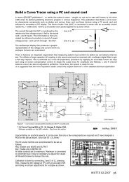
There are various methods that can be used to generate a <strong>SWR</strong> related signal. I am a fan of the current / voltage<br />
sensing method. The disadvantage of this system is that one needs an active (powered) circuit to generate the<br />
indication. The advantage is that it is highly accurate <strong>and</strong> very wide b<strong>and</strong>. In other words, it does not suffer from<br />
the loss of accuracy that passive systems are prone to. But hey, every other <strong>meter</strong> on my desk has a little 9V<br />
battery in it so why not the <strong>SWR</strong> <strong>meter</strong>. This is the basic circuit:
In the above circuit, the voltage is dropped over the resistor R1 <strong>and</strong> adjusted by the trim-pot. The current passing<br />
through the signal line that L1 is looped around will generate a voltage across L1. The current trim-pot adjusts the<br />
amplitude of this signal. A low power sensing circuit may need an extra turn or two. The current <strong>and</strong> voltage sense<br />
signals can now be routed to an oscilloscope where one can now view the voltage <strong>and</strong> current signals. With this<br />
system it does not matter which side you connect the <strong>antenna</strong> or the transceiver, as the signal is AC.<br />
There will be a small phase shift over L1 between the current passing through signal line that L1 is looped around<br />
<strong>and</strong> the voltage generated across L1 <strong>and</strong> that phase shift will increase as the frequency increases. We therefore put<br />
an identical coil in the voltage sensing line that will phase shift the voltage sense signal by the same amount<br />
thereby eliminating the inductive phase shift effect of the current sensing coil.<br />
Calibration.<br />
Now we connect a dummy load of the impedance that we wish to calibrate the circuit for. In our case, 50 ohms. We<br />
then send an RF signal through the circuit <strong>and</strong> we calibrate the trim-pots so that the voltage sense signal <strong>and</strong> the<br />
current sense signal are the same amplitude. This is what your trace should look like.<br />
The current <strong>and</strong> the voltage sense signals are the same size <strong>and</strong> they are in phase representing a perfect load.
Usage<br />
Right so now you have this thing connected between a transceiver <strong>and</strong> a dummy load. Now on to the next step.<br />
Disconnect the dummy load <strong>and</strong> connect the <strong>antenna</strong> <strong>and</strong> set you transceiver to the lowest output power setting that<br />
you can. Select the AM mode (because that usually generates 50% of the power of the CW mode, but, failing that,<br />
select the CW mode in the lowest power setting that you can.) Now, key the transmitter <strong>and</strong> look at the two<br />
waveforms.<br />
One of several things is going to happen. You may see that :<br />
1) The relationship between the two signals will be the same as they were when you had the dummy load<br />
connected, which means that your <strong>antenna</strong> is beautiful <strong>and</strong> you can now go <strong>and</strong> do something else.<br />
2) The voltage trace is larger that the current trace, which means that your <strong>antenna</strong> impedance is high.<br />
3) The current trace is larger than the voltage trace, which means that your <strong>antenna</strong> impedance is low.<br />
4) The voltage trace precedes the current trace which means that your <strong>antenna</strong> is inductive in nature (too long)<br />
5) The voltage trace follows the current trace which means that your <strong>antenna</strong> is capacitive in nature (too short)<br />
6) And then, you may find that the current <strong>and</strong> voltage waveforms are completely different in appearance<br />
which means that your <strong>antenna</strong> system is resonating on an harmonic of the input frequency (which is not<br />
good at all)<br />
So now, you go about correcting your <strong>antenna</strong> system in the manner as indicated by adjusting your feed-line <strong>and</strong><br />
<strong>antenna</strong> dimensions.<br />
Feedline correction.
Connect your transmitter to your <strong>SWR</strong> <strong>meter</strong>, through your feedline, to your dummy load. (in other words, put an<br />
RF plug on the end of your feedline <strong>and</strong> bring it back to your workbench <strong>and</strong> plug it into the dummy load.)<br />
Measure the amplitude of the voltage signal at the transmitter side. I usually adjust the voltage trace on the scope to<br />
reflect 100% of the display (as my scope display has a % setting) .<br />
Is there a phase variation between the voltage <strong>and</strong> current traces? This will indicate that your feedline is either to<br />
long or to short. You will have to make the appropriate correction. Once you have a resistive feedline, that is not<br />
reactive (inductive or capacitive) you can then proceed to the next stage of your setup.<br />
Feedline losses.<br />
Now, connect the feedline directly to your transceiver <strong>and</strong> place the <strong>SWR</strong> pickup between the end of the feedline<br />
<strong>and</strong> your dummy load. Now key the transmitter <strong>and</strong> look at the amplitude of the voltage trace. It should be a<br />
percentage of the signal amplitude when the pickup was placed between the transmitter <strong>and</strong> the feedline. To help<br />
me to figure things out at a glance, I printed out this calculating disk on my computer.<br />
Next page >
Let us say for example that the voltage amplitude<br />
at the dummy load is 50% of the voltage at the<br />
transmitter (to make the math easy) . That means<br />
that the power at the output point of the<br />
transmitter is 2X the power at the input point of<br />
the <strong>antenna</strong>, which is equivalent to a 3dB (0.3B)<br />
loss as indicated by the red mark on the<br />
calculating disk, (left) . So 400 watts forward is<br />
losing 200 watts over your feedline. (not good) .<br />
Now, if you were to insert a forward/reflected<br />
power <strong>meter</strong> between the end of the feedline <strong>and</strong><br />
the input to the <strong>antenna</strong> <strong>and</strong> you were to get a<br />
reflected power reading of 50 watts, you would<br />
get 25 of those watts back at the output of your<br />
transmitter (which is the power dissipated by your<br />
average soldering iron- which means your output<br />
circuit will now try to de-solder itself).<br />
25/400*100 = 6.25% <strong>and</strong> if u look at the table<br />
below, 6.25% ~ a <strong>SWR</strong> of 1.65:1 which in turn<br />
puts your effective output power at 93.75% at<br />
your transmitter. But because of your 3dB feedline<br />
loss, 47% of your power will be radiated by your<br />
feedline as heat <strong>and</strong> cross channel noise leaving<br />
only 47% of your original 400 watts (187 watts)<br />
being transmitted as effective RF through you<br />
<strong>antenna</strong> system, <strong>and</strong> that is it in a nutshell.
* ERP = Percentage of Effective Radiated Power<br />
<strong>SWR</strong> READING % OF LOSS ERP* WATTS AVAILABLE of 100 out<br />
1.0:1 0.0% 100.0% 100<br />
1.1:1 0.2% 99.8% 99.8<br />
1.2:1 0.8% 99.2% 99.2<br />
1.3:1 1.7% 98.3% 98.3<br />
1.4:1 2.8% 97.2% 97.2<br />
1.5:1 4.0% 96.0% 96.0<br />
1.6:1 5.3% 94.7% 94.7<br />
1.7:1 6.7% 93.3% 93.3<br />
1.8:1 8.2% 91.8% 91.8<br />
2.0:1 11.1% 88.9% 88.9<br />
2.2:1 14.1% 85.9% 85.9<br />
2.4:1 17.0% 83.0% 83.0<br />
2.6:1 19.8% 80.2% 80.2<br />
3.0:1 25.0% 75.0% 75.0<br />
4.0:1 36.0% 64.0% 64.0<br />
5.0:1 44.4% 55.6% 55.6<br />
6.0:1 51.0% 49.0% 49.0<br />
7.0:1 56.3% 43.8% 43.8<br />
8.0:1 60.5% 39.5% 39.5<br />
9.0:1 64.0% 36.0% 36.0<br />
10.0:1 66.9% 33.1% 33.1
A <strong>SWR</strong> sensing amplifier circuit using <strong>precision</strong> rectifiers.<br />
In order to use the <strong>SWR</strong> pickup in the field, (because it is not always practical to drag a scope around with you, the<br />
following circuits can be used to give you the relevant information on a portable field <strong>meter</strong>.<br />
This circuit uses U1 as a differential instrumentation amplifier. The output of U1 is proportional to the difference<br />
between the voltage <strong>and</strong> current sense signals. Ie. If the inputs are identical, then there is no output. U2 <strong>and</strong> U3 are<br />
<strong>precision</strong> rectifiers reflecting the <strong>SWR</strong> <strong>and</strong> Calibrate levels. The output is calibrated using the <strong>SWR</strong> CALIBRATE<br />
adjustment of R3/R4.
An impedance indicator<br />
The following circuit can be used to show the impedance of the <strong>antenna</strong> system.<br />
The <strong>meter</strong> is a center zero type. If the voltage <strong>and</strong> the current sense signals are equal then the output of the voltage<br />
<strong>and</strong> the current <strong>precision</strong> rectifiers is also equal <strong>and</strong> there will be no deflection on the <strong>meter</strong>, which would in turn,<br />
indicate a 50-ohm load. If the voltage is higher than the current, that will indicate an impedance higher than 50<br />
ohms. If the current is higher than the voltage, that will indicate an impedance of less than 50 ohms. RCAL should<br />
be chosen according to the power level you wish the circuit to operate at.
Reactive Load <strong>and</strong> Phase angle indicator<br />
This circuit can be used to indicate whether a load<br />
is inductive or capacitive <strong>and</strong> the phase angle of the<br />
reflected power. U8 <strong>and</strong> U9 convert the Current<br />
<strong>and</strong> Voltage sine waves into square waves. These<br />
signals are fed to the Data <strong>and</strong> Clock inputs of a<br />
Data latch. The current input clocks the state of the<br />
voltage signal into the data latch. If the current goes<br />
high before the voltage, a 0 is clocked in making Q<br />
= 0 <strong>and</strong> /Q = 1. This turns on the Capacitive load<br />
LED. If the voltage goes high before the current,<br />
the current input will clock, a 1 is clocked in<br />
making Q = 1 <strong>and</strong> /Q = 0. This turns on the<br />
inductive load LED.<br />
The current <strong>and</strong> voltage square waves are applied<br />
to the input of an exclusive or gate which will<br />
reflect the difference between the two square waves<br />
as a pulse width modulated square wave<br />
proportional to the phase angle difference. This<br />
PWM square wave is integrated through R18/C11<br />
<strong>and</strong> the output voltage of 0-5V represents a phase<br />
angle of 0-180 degrees, leading or trailing as shown<br />
by the capacitive / inductive load indicator.
Antenna voltage <strong>and</strong> current.<br />
This is a pretty simple circuit consisting of two <strong>precision</strong> rectifiers that will give a DC output corresponding to the<br />
amplitudes of the <strong>antenna</strong> current <strong>and</strong> voltage. One can pre-scale them into a multi function <strong>meter</strong> or one can feed<br />
them into a little micro-controller which can then multiply the two signals together <strong>and</strong> give you an output<br />
proportional to the product of the two representing the power. Watts = Volts X Amps. You can of course use the<br />
same device to divide the volts by the amps <strong>and</strong> give you an output reflecting the load impedance.<br />
In fact, by using the above circuits to feed a micro controller, (that is if you are into playing with micro controllers)<br />
you can digitize the various signals, send the values to your computer, <strong>and</strong> have your PC do a full workup on your
<strong>antenna</strong> system. Then, hook up a 74HCT4046 <strong>and</strong> you can get a full spectrum profile for your <strong>antenna</strong> system <strong>and</strong><br />
that piece of kit shouldn’t cost you more than about two or three hundred r<strong>and</strong>s.<br />
I hope that this has been of use.<br />
Thanks <strong>and</strong> best regards.<br />
Mike Brink.<br />
ZR6BRI.<br />
Please feel free to mail me if you have any questions.<br />
Please visit our club website at www.zs6pot.org for more kit <strong>and</strong> project stuff<br />
Please visit my personal website at www.zr6bri.co.za for more kit stuff <strong>and</strong> to check out what I’m busy with.<br />
© 2007 M Brink. All circuits featured in this article are my own design <strong>and</strong> all the contents of this article is subject<br />
to copyright law. Permission is hereby given for the free use of the above for personal <strong>and</strong> experimental purposes<br />
but you are kindly requested to ask permission before using these circuits in commercial equipment. Not that I<br />
specifically want any renumeration, it is just that it would be nice to know where my ideas are being used. Thank<br />
you.