Display - Pretoria Amateur Radio Club
Display - Pretoria Amateur Radio Club
Display - Pretoria Amateur Radio Club

Create successful ePaper yourself
Turn your PDF publications into a flip-book with our unique Google optimized e-Paper software.
WATTS<br />
01-2011<br />
Year 81 + 1m<br />
Monthly newsletter of the <strong>Pretoria</strong> <strong>Amateur</strong> <strong>Radio</strong> <strong>Club</strong><br />
Maandelikse nuusbrief van die <strong>Pretoria</strong> <strong>Amateur</strong> <strong>Radio</strong> Klub.<br />
PARC, PO Box 73696 Lynnwood Ridge 0040, RSA<br />
web<br />
http://www.parc.org.za mail: zs6pta@zs6pta.org.za<br />
ZR6FD logo<br />
Drukwerk<br />
printing<br />
ZS6JPL<br />
Papier / Paper<br />
ZS6JPL<br />
Bulletins: 145,725 MHz 08:45 Sundays/Sondae<br />
Relays: 1.840, 3.700, 7.066, 10.135, 14.235, 51.400, 438.825, 1297 MHz<br />
Activated frequencies are announced prior to bulletins<br />
Swapshop: 2m and 7.066 MHz Live on-air after bulletins<br />
Bulletin repeats Mondays | herhalings : Maandae 2m 19:45<br />
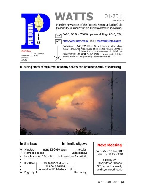
R7 facing storm at the retreat of Danny ZS6AW and Antoinette ZR6D at Waterberg<br />
In this issue<br />
In hierdie uitgawe<br />
Next Meeting<br />
● Minutes none 12-2010 geen Notules<br />
Date: Next Wed Meeting 12 Jan 2011<br />
● Member’s pages<br />
Lede-bladsye<br />
Time: 1319:30 Jan 2010 for 20:00<br />
• Member news / Activities Lede-nuus en Aktiwiteite<br />
•<br />
Time: Building 13:30 for #414:00<br />
• Technical The ZS6BKW antenna University Tegnies PMC of <strong>Pretoria</strong>.<br />
• All about baluns<br />
S/E corner Keunig University str<br />
• A sensitive RF detector circuit<br />
and Lynnwood Silverton roads<br />
● Page eight<br />
Bladsy agt<br />
WATTS 01 -2011 p1
PARC Management team / Bestuurspan Aug. 2010 - Aug. 2011<br />
Committee members<br />
Chairman, SARL liaison Pierre Holtzhausen ZS6PJH chairman@zs6pta.org.za 012-655-0726 082-575-5799<br />
Viice-Chairman, Fleamarket Alméro Dupisani ZS6LDP fleamarket@zs6pta.org.za 012-567-3722 083-938-8955<br />
Secretary, Treasurer Richard Peer ZS6UK treasurer@zs6pta.org.za 012-333-0612 082-651-6556<br />
Repeaters, Technical Craig Symington ZS6RH technical@zs6pta.org.za 083-259-3233<br />
Rally co-ordinator Johan de Bruyn ZS6JHB rally@zs6pta.org.za 012-803-7385 082-492-3689<br />
Web co-ordinator , Secretary Graham Reid ZR6GJR webmaste@zs6pta.org.za 083-701-0511<br />
Social co-ordinator Doréén de Bruyn ZR6DDB 012-803-7385 082-857-9691<br />
Willie Greyling ZR6WGR social@zs6pta.org.za 082-940-2490<br />
Co-opted / Geko-opteer:<br />
Auditor<br />
Elma Basson<br />
WATTS newsletter/Kits Hans Kappetijn ZS6KR editor@zs6pta.org.za 012-333-2612 072-204-3991<br />
Asset control Andre van Tonder ZS6BRC andreh.vtonder@absamail.co.za 361-3292 082-467-0287<br />
Klubfasiliteite, Vlooimark Willie Greyling ZR6WGR facility@zs6pta.org.za 082-940-2490<br />
Rallies Johann de Beer ZR6YV 011-918-1060 082-857-1561<br />
Contest co-ordinator Pieter Human ZS6PA contest@zs6pta.org.za 012-800-2888 082-565-6081<br />
Training co-ordinator Fritz Sutherland ZS6ASF training@zs6pta.org.za 012-811-3875 083-304-0028<br />
Historian, Awards Tjerk Lammers ZS6P zs6p@iafrica.com 012-809-0006<br />
Public relations Alméro Dupisani ZS6LDP fleamarket@zs6pta.org.za 12-567-3722 083-938-8955<br />
Minutes of the monthly club meeting of the <strong>Pretoria</strong> <strong>Amateur</strong> <strong>Radio</strong> <strong>Club</strong><br />
NB: The meeting was cancelled for the December holidays 2010.<br />
Birthdays<br />
Jan.<br />
Verjaarsdae<br />
Jan. Anniversaries<br />
Herdenkings<br />
05 Pierre ZS6PJH 03 Magriet and Tobie ZS6ZX ( )<br />
06 Carmyn, daughter of Gary ZR6GK 05 Louise and Alm‚ro ZS6LDP (20 )<br />
06 Brendan ZS6BW, Son of Peter ZS6PJ 07 Doreen ZR6DDB and Johan ZS6JHB ( 22 )<br />
08 Darren ZR6TY, son of Selma and Joe ZS6TB 20 Helga and Hans-Peter ZS6AJS ( 50 )<br />
13 Carol, lv van Hein ZS6Q<br />
20 Errol ZR6VDR<br />
20 Theresa, dogter van Magriet en Tobie ZS6ZX<br />
23 Mark ZS6USA<br />
25 Magriet, lv van Tobie ZS6ZX<br />
31 Elize, lv van Pieter ZS6PA<br />
Joys and Sorrows | Lief en Leed<br />
Molly ZR6MOL has become unwell again during the Christmas period.<br />
Diary | Dagboek (UTC times)<br />
Jan 08-09 Hunting Lions on the Air 00:00-24:00<br />
09 DARC 10m Contest 09:00-10:59<br />
12 SARL Office re-opens<br />
15-16 Hungarian DX Contest 12:00-12:00<br />
20 Deadline for2011 RAE bursary submissions<br />
28-30 CQ 160m Contest CW 22:00-21:59<br />
29-30 REF Contest CW 06:00-18:00<br />
UBA Contest SSB 13:00-13:00<br />
30 Deadline Construction Competition phase 1<br />
ZS7 Antarctica operation<br />
Gerard de Jong, ZS6KX, departed on board the SA Agulhas from<br />
Cape Town Harbour at 14:00 on 8 December 2010 for Antarctica.<br />
If possible, he intends operating from the Sanae IV Base.<br />
He will initially operate as ZS7/ZS6KX as departure was at short<br />
notice. A full ZS7 call sign will be allocated some time later.<br />
Arrival will be on 22 December.<br />
Snippets|Brokkies<br />
6m is coming alive! – monitor 50,200 MHz and beam south.<br />
WATTS 01 -2011 p2
The ZS6BKW antenna<br />
6 bands (40 / 20 / 17 / 12 / 10 / 6 m.) without a tuner or traps<br />
Ed: Reprinted with permission from www.instantladderline.co.za – (check out their spreader product)<br />
When OM Louis Varney G5RV designed his famous antenna in the 1950's, it performed excellently with the equipment of that day<br />
and age. With today's radio's, on the other hand, things are different. This led OM Brian Austin, ex ZS6BKW (now G0GSF) to<br />
redesign the G5RV, using modern antenna modeling software - something that was was not available when the G5RV was designed.<br />
He found that shortening the two legs of the G5RV dipole and lengthening the matching stub (the balanced feed line) resulted in an<br />
antenna that provides a good match to the 50 ohms impedance of today's transistorized radio's. This allows the antenna to be used<br />
on five bands without an antenna tuner! And as an added bonus, it was later discovered that the ZS6BKW antenna covers not five<br />
but six bands, as it does 6m, too, something that the original G5RV did not cover at all!<br />
However, there is some bad news, too. On 80m and 15m the ZS6BKW design performs less well than the original G5RV, while on<br />
30m it is just as bad. Also, the antenna's performance appears to be rather dependent on how well it is installed. If it is not high<br />
enough above ground or does not keep sufficiently clear of trees, buildings or conductive objects, performance can be affected<br />
rather seriously. However, in this respect it does not differ markedly from the original G5RV, which behaves similarly.<br />
The horizontal part of the antenna (the dipole) can be made from electric fence wire, which is an excellent choice for this<br />
application. It has a better surface conduction and shows less corrosion than is the case with untreated steel wire, and can be put<br />
under mechanical strain without stretching over time like copper wire does. In the original G5RV design, the dipole length (L1) was<br />
31.1m while the matching section (L2) was 10,37m of open line. In the optimized design by ZS6BKW the dipole itself is slightly<br />
shortened to a length (L1) of 28.4m, while the matching section (L2) is longer, and depends on the velocity factor of the feed line<br />
used. Different versions of this design circulate on the Internet, typically using 300 ohm tape (the type with a velocity factor of 0.85,<br />
and L2 being 11.1m) or using 450 ohm window line (with L2 being 12.2m).<br />
However, the best, cheapest and easiest way to make the matching section is<br />
to use ladder line, which can be easily constructed using Instant Ladder Line<br />
clip-on wire spreaders. In this case L2 is 13.08m.<br />
While various literature claims that a 1:1 (or almost 1:1 match) without a<br />
tuner on various frequencies can be achieved, this seems more due to the<br />
lossy coax used by the ham doing the measurements than the antenna's<br />
performance! (Note that because lossy coax also dampens the reflected wave,<br />
coax loss will result in a better SWR measurement at the transmitter!) In OM<br />
Brian's own 1985 publication he merely speaks of "an acceptable match",<br />
better than 2:1 on five bands, which seems much more realistic. And that is<br />
fine - better than 2:1 is more than sufficient. A 1:1 match is not required,<br />
contrary to what many hams these days believe!<br />
The table below lists a few SWR figures that compare theoretical (calculated)<br />
values found in literature, to the measured values of the author's own<br />
ZS6BKW antenna, as well as to the G5RV. (Only theoretical values for the<br />
latter, but past measurements done on actual G5RV's show that these match<br />
the actual performance fairly well.)<br />
Band 80 40 30 20 17 15 12 10 6<br />
ZS6BKW, literature 8.3 1.1 87 1.2 1.4 80 1.2 1.5 1.5<br />
ZS6BKW, measured >10 1.7 >10 2 1.4 >10 2 2 1.7<br />
G5RV 3.2 4.8 >10 2.5 >10 6.8 3.6 >10 N/A<br />
WATTS 01 -2011 p3
(Note: these are the "best" SWR figures; they will of course vary while tuning across the band. The fact that the measured SWR<br />
values are higher than the ones in literature is probably due to "end effects".)<br />
A lot of "religious debate" on whether or not to use a balun between the coax and the matching section has taken place over the<br />
years. Most of it is based upon OM Varney's own remarks on the subject, and experiments by other hams. However, Varney's<br />
statement that he did not notice any difference with or without a balun, and the conclusion that one is therefore better off without<br />
one, date from the 1960's and apply to the equipment of that era. Many hams, meanwhile, have experimented with 4:1 voltage<br />
baluns, which introduce a mismatch because the feed point impedance of the matching stub is much close to 50 than to 200 ohms.<br />
The fact of the matter is that any way you look at it, it is never a good idea to attach an unbalanced coaxial cable directly to a<br />
balanced load (which this antenna is). It introduces unbalanced currents in a balanced system, thus causing it to perform wildly<br />
different from what theory predicts, not to mention the fact that it causes shield currents in the coax, resulting in RF in the shack<br />
and TVI. A proper 1:1 current balun (.e. a choke) between the coax and the balanced antenna feed point is therefore recommended.<br />
Everything you always wanted to know about baluns but were afraid to ask<br />
The antenna terminal on a modern radio is coaxial (usually a PL259 connector) and therefore unbalanced. The radio chassis sits at<br />
zero potential (if all is well, that is) and the center pin of the coaxial connector carries the RF signal. A dipole antenna, on the other<br />
hand, which is often used for HF operation, is a balanced antenna. Simply connecting an unbalanced system to a balanced system is<br />
never a good idea! If coaxial cable is involved, its shield will carry strong RF currents which will be radiated where they will do the<br />
least good. This will cause RF in the shack, TVI, etc. The radio's chassis and everything connected to it will be "hot", resulting in<br />
blistered fingers due to RF burns.<br />
Obviously some conversion from unbalanced to balanced is required in order to connect these two different systems. Enter the<br />
balun. As the name (bal-un) implies, a balun matches a balanced system to an unbalanced one. In addition to that, baluns can (but<br />
not necessarily do) perform impedance transformation as well. The 4:1 balun, which matches a 50 ohms unbalanced radio to a 200<br />
ohms balanced dipole, is a popular example.<br />
Voltage vs. current baluns<br />
Baluns can employ either one of two principles. On the one hand there are voltage baluns, which are essentially auto-transformers.<br />
On the other hand there are current baluns which are based upon the principle of suppressing or neutralizing common-mode<br />
currents. And in-depth treatment of the theories behind the various balun systems and how they interact with feed lines is beyond<br />
the scope of this article. Instead, let's have a look at the four baluns that are most common in practice, and see how they compare.<br />
The 4:1 voltage balun is the most commonly found balun. The<br />
voltage balun (also known as the "Ruthroff" balun) is actually a<br />
simple transformer. Current from the unbalanced terminal (the<br />
center pin of the coax) is fed directly to one of the balanced<br />
terminals, and runs through the top half of the transformer<br />
windings as well. This induces a similar current in the bottom half<br />
of the transformer windings, but because the top of the bottom<br />
transformer half is at zero potential, the lower balanced terminal<br />
develops a voltage equal but opposite to the upper one.<br />
While this design is the most common one, it is by no means the<br />
best! The main problem is its flawed symmetry. The impedance of<br />
the top half of the transformer is switched in parallel with the<br />
(typically 50 ohms) impedance connected to the unbalanced<br />
terminal, while the lower half of the transformer is not. Especially<br />
at higher frequencies, where the inductance of the transformer<br />
windings increases, this means that the voltage developed across<br />
the upper transformer half is loaded by the unbalanced input<br />
impedance, and therefore drops. This is not true for the lower half<br />
of the transformer. As a result the signal across the balanced<br />
terminals is far less balanced for higher frequencies. This<br />
unbalance will cause a balanced feed line to radiate RF.<br />
The 1:1 voltage balun is a variety on the previous one. Here the<br />
current drawn from the unbalanced terminal (the center pin of the coax) is fed not through one but through two transformer<br />
windings in series. The upper balanced terminal is connected to the connection point of the two windings. The third (bottom)<br />
transformer winding forms an arrangement similar to the one described above. In this configuration the amplitude of the unbalanced<br />
signal is equal to that of the balanced signal, since both of them are developed across the same number of transformer windings. In<br />
the 4:1 voltage balun the balanced signal was developed across twice the number of windings compared with the unbalanced signal,<br />
which means (this being a transformer) that the voltage is doubled while the current is halved, resulting in an impedance<br />
transformation factor of 4:1. The 1:1 balun performs neither voltage nor current transformation, hence the impedance<br />
transformation factor is 1:1. It does, however, experience the same problems with flawed symmetry and the resulting unbalance at<br />
higher frequencies!<br />
The 1:1 current balun is also known as the Guanella balun or a<br />
choke. This is one of the simplest baluns. It is based on<br />
suppression of the common mode current in the feed line. The<br />
current through the upper winding induces an equal but opposite<br />
current in the bottom one, with a voltage developed across the<br />
WATTS 01 -2011 p4
ottom winding equal and opposite to the one across the top. This annuls the voltage on the bottom balanced terminal, thus<br />
keeping the chassis of the unbalanced side at zero potential. In practice this balun often takes the form of a coaxial cable wound<br />
into a coil. Its main disadvantage is that its efficiency depends entirely on the coil inductance, which should be infinite in order to<br />
achieve 100% suppression of feed line common mode currents. In the real world this inductance is finite and frequently low, which<br />
limits the efficacy of this balun.<br />
The 4:1 current balun (Guanella balun) may look a bit<br />
confusing, but in fact isn't all that hard to understand. It consists<br />
essentially of two 1:1 Guanella (current) baluns, the unbalanced<br />
sides of which have been switched in parallel, while the balanced<br />
sides are in series. This means that both 1:1 baluns will each<br />
develop the same voltage on the right hand side as on the left<br />
hand side (they have a transformation factor of 1:1 after all) but<br />
because on the balanced side these two voltages are switched in<br />
series, the voltage on that side doubles. With twice the voltage<br />
(and therefore half the current) at the balanced side, the result is<br />
a 4:1 impedance transformation. Both 1:1 baluns which make up<br />
the 4:1 variety may be wound on different cores, or on the same<br />
core. The main disadvantage of this particular balun is that the<br />
characteristic impedance of the windings themselves should be<br />
twice that of the unbalanced impedance and half that of the<br />
balanced impedance. In other words, in order to get a 1:1 SWR at<br />
the 50 ohms side, the characteristic impedance of the windings ideally should be exactly 100 ohms, which is extremely hard to<br />
achieve in practice. On the other hand, while the SWR meter may not show a 1:1 match with a dummy load, the symmetry of the<br />
signals at the balanced end of this balun will always be 100%, which cannot be said for the other three balun designs shown above!<br />
Balun cores: air, ferrite or powdered iron<br />
A 4:1 Ruthroff (voltage) balun on<br />
a toroid, for indoor (shack) use.<br />
A 4:1 Guanella (current) balun on a single toroid,<br />
made from insulated wire and cable ties.<br />
Many balun designs can be found on the Internet. A number of these are "air wound" baluns, consisting of wire or coax wound<br />
across a former (e.g. a plastic tube) filled with air. This makes sense in countries where four figure power levels are legal (or at least<br />
common) since an air core is, for all practical purposes, impossible to magnetically saturate. In other countries such as South Africa,<br />
however, where 100W is the most common maximum power level, and with a happy few owning a "foot warmer" that pumps out<br />
200 or even 400W, it is very well possible to use properly selected powdered iron or ferrite cores without causing these cores to<br />
saturate. Since the proper functioning of all baluns discussed here depends on self-induction and magnetic coupling, the higher<br />
magnetic permeability of a core is preferable to the low permeability of air. Baluns based on air cores often leave a lot to be desired,<br />
with their efficacy being limited by the low induction and loose coupling of the windings, especially on lower frequencies.<br />
Various options are available for balun cores. The top of the range (and of course the most expensive option) is the ferrite toroid<br />
core. These can be obtained in South Africa from suppliers such as Mantech or RS components. They can be hard to find and<br />
somewhat pricey, but they are available. Ordering ferrite cores in larger batches may be easier than obtaining single ones, so<br />
consider making it a club project! Various ferrite mixes are available. Without going into the details of ferrites (about which many<br />
volumes have been written), an excellent all-round ferrite mix for balun cores is 4C65. The amount of power the balun can handle is<br />
in no small measure determined by the size of the toroid - the bigger, the better. In practice a 36mm toroid is more than sufficient<br />
to handle 100W, provided that the impedance mismatch isn't too great.<br />
As an alternative to ferrite, powdered iron cores are available. These tend to be a bit cheaper than ferrites. A well-known type is the<br />
T-200. These cores have a much lower permability than the 4C65 ferrite, which means that they won't saturate as easily at higher<br />
power levels. On the other hand, the price we pay for that lower permeability is a lower induction and less tightly coupled windings.<br />
Fortunately there is a cheap alternative to toroid cores, which can be found in just about every radio ham's junk box. These are the<br />
ferrite rods salvaged from the old ferrite "loopstick" antenna's in AM radio's! A ferrite rod with a length of 10 or 12 cm and a<br />
diameter of 10-15mm (not critical) will do very nicely for power levels up to 100W. Multiple ferrite rods can be taped together to get<br />
a chunkier core that will handle even higher power levels. If laquered copper wire is used for the windings, put some plastic tape or<br />
heat shrink tube over the ferrite for extra insulation.<br />
WATTS 01 -2011 p5
Balun construction<br />
Baluns can be wound on a ferrite core using insulated wire, which can be held in place with cable ties. Laquered copper wire can<br />
also be used, but this is more difficult to apply since it is less flexible. When winding laquered copper wire onto a ferrite rod, be<br />
careful not to apply too much force in shaping the wire, because ferrite rods are a brittle ceramic and break easily!<br />
A 4:1 Ruthroff (voltage) balun wound on ferrite rods, using laquered wire.<br />
For more bandwidth the spacing between the windings<br />
should be increased. This balun will take at least 100W.<br />
A 1:1 Guanella (current) balun, also known<br />
as a "choke", made by winding 3 layers<br />
of RG58 coax on a ferrite rod.<br />
A choke (1:1 Guanella) balun) can be made by winding an odd number of layers of coax onto a ferrite rod. This works better than<br />
the usual method of just winding the coax into ten or twelve loops, because looped coax has as very low permeability (it is an airwound<br />
coil) and the capacitance between both ends of the coil is very high.<br />
Baluns are generally<br />
easy to build. If they<br />
are intended for outdoor<br />
use, they need to be<br />
weatherproofed. A good<br />
way to do this is to use<br />
plastic drain pipe, which<br />
can be cheaply obtained<br />
from a local plumber,<br />
along with matching<br />
end caps. Baluns wound<br />
on ferrite rods can be<br />
housed in pieces of pipe<br />
with a length of 10-<br />
20cm (depending on the<br />
size of the rod) while<br />
toroids may be housed in short sections of pipe which essentially only serve to hold two end caps tightly together. A small amount of<br />
silicone sealant can provide further waterproofing. Use as little sealant as possible, so that you can remove the end caps later if<br />
repairs or changes should be necessary.<br />
Baluns for indoor use can be housed in just about any enclosure that is on hand. Plastic is preferable, though. If metal housings are<br />
used, ensure that all wires and cores are kept well clear of any metal parts.<br />
Winding diagrams<br />
On the website are generic winding diagrams for typical balun types. The number of windings is intended as a starting point only.<br />
The ideal number depends on the desired frequencies and bandwidth, as well as on the core material used, i.e. the ferrite or<br />
powdered iron mix. The bandwidth can be changed by varying the spacing between the windings. Some experimentation may be<br />
necessary.<br />
Are plasma TVs killing radio - RSGB appeals for evidence Posted in Wireless, 12th August 2010<br />
(Ed: Similar problems were reported some time ago by Dutch hams in their newsgroups)<br />
The <strong>Radio</strong> Society of Great Britain is asking anyone with a plasma TV to let it know if they‘ve had trouble getting <strong>Radio</strong> 4 lately.<br />
The <strong>Radio</strong> Society of Great Britain represents the radio ham community, though it sees itself as having a wider remit. When not<br />
organising competitions to see who has the biggest beard can transmit a 10MHz signal furthest, the RSGB tries to protect the<br />
interests of radio users of all kinds by tracking possible causes of interference, which prompts its latest appeal.<br />
Recently the interference effort has been focused on mains networking kit - people running Ethernet signals over in-home electrical<br />
wires - but the Society reckons that plasma TVs are another source of interference worthy of greater attention.<br />
Anecdotal stories abound of plasmas putting out interference below 30MHz, and even extending into the higher frequencies where<br />
commercial radio can be found, but the Society is trying to cast a wider net to see if it's a genuine problem.<br />
The plan is to make a presentation to CISPR (the International Special Committee on <strong>Radio</strong> Interference) in the next few weeks if<br />
enough complaints can be accumulated - so if you‘ve got a plasma and you think it's plotting against your radio, drop the RSGB a<br />
line at plasma.tv@rsgb.org.uk.<br />
WATTS 01 -2011 p6
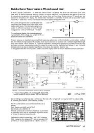
An old but useful idea for a sensitive field strength meter (WW March 1978)<br />
35<br />
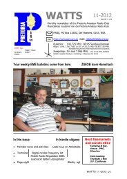
F2 Critical Frequency and 4000 km MUF<br />
<strong>Pretoria</strong> - January 2011<br />
Long Term HF Propagation<br />
Prediction for December<br />
2010 courtesy ZS6BTY<br />
(see also our website propagation tab)<br />
MHz<br />
28<br />
21<br />
14<br />
7<br />
0<br />
0 2 4 6 8 10 12 14 16 18 20 22 24<br />
foF2<br />
MUF East<br />
MUF North<br />
MUF West<br />
MUF South<br />
DX Operating<br />
The graph shows the 4000 km maximum<br />
useable frequency (MUF) to the East, North,<br />
West and South from <strong>Pretoria</strong> for the first hop<br />
using the F2 layer.<br />
Local Operating<br />
The F2 critical frequency (foF2) is the<br />
maximum frequency that will reflect when you<br />
transmit straight up. E-layer reflection is not<br />
shown.<br />
UTC<br />
QRV Services offers the following expertise:<br />
• General equipment repairs and calibration<br />
• Small-scale design and manufacturing<br />
• Technical writing<br />
• 3 rd Party scrutiny of projects and documents<br />
• Expert TV repairs and second-hand TV sales<br />
• MFJ 259/69 Analyzer repairs and calibration<br />
and products:<br />
• Morse Mate<br />
• Legal limit 40m dipole traps<br />
• <strong>Radio</strong> power supply OV protection kits<br />
• Nissei SWR/Power meters HF and VHF/UHF<br />
• Connectors RF and DC<br />
• Plug-in triple sequential industrial timer<br />
Contact Hans at 012-333-2612 or 072-204-3991<br />
WATTS 01 -2011 p7
Ofcom slaps down ham botherer<br />
Drive-by signal jammer closed down<br />
Posted in Wireless, 26th November 2010 11:17 GMT<br />
A 63-year-old man from Hull has pleaded guilty to driving by<br />
the homes of radio hams purely for the joy of interfering<br />
with their hobby.<br />
In a case brought by Ofcom, Clive McMurray appeared in<br />
Hull Crown Court and admitted operating a radio transmitter<br />
without a licence. He was given a four-month sentence<br />
suspended for 18 months as well as forfeiting his radio kit<br />
and landing a curfew preventing him from roaming the<br />
streets between 7pm and 7am at night.<br />
Driving around in his van, Mr McMurray would park up<br />
outside the home of an operating radio ham and start<br />
jamming the signal or broadcasting his own (or both).<br />
Quite why he did this remains a mystery, but despite initially<br />
denying the charges in September he pleaded guilty on<br />
Monday.<br />
Triangulating a radio source is pretty easy, but if it's moving<br />
around - mounted, say, in a Toyota van - then it's a good<br />
deal harder, and Ofcom has been pursuing the case since<br />
May 2009.<br />
Operating a radio transmitter without a licence is illegal, and<br />
Ofcom has the power to prosecute in such cases (as it did<br />
this time). In most cases a stern telling off is sufficient, and<br />
such powers are reserved for shutting down pirate radio<br />
stations where confiscation of the equipment is more<br />
important than the punishment imposed.<br />
We've no idea why Clive McMurray wanted to upset the<br />
radio hams, who are mostly harmless at worst, but hopefully<br />
he'll now find a more productive hobby, and one he can do<br />
at home.<br />
The Earth's magnetic poles A reversal of the Earth's magnetic poles would certainly make<br />
life interesting for radio amateurs. The Geomagnetic North Pole is currently moving north under the Arctic<br />
Sea at about 40 km per year, dragging the auroral oval along with it and affecting polar path propagation.<br />
While it has been 3/4 of a million years since the last reversal, no one knows whether we are overdue for<br />
a flip-flop and the field strength seems quite strong.<br />
http://science.nasa.gov/science-news/science-atnasa/2003/29dec_magneticfield<br />
WATTS 01 -2011 p8