Build a Curve Tracer using a PC and sound card
Build a Curve Tracer using a PC and sound card
Build a Curve Tracer using a PC and sound card

You also want an ePaper? Increase the reach of your titles
YUMPU automatically turns print PDFs into web optimized ePapers that Google loves.
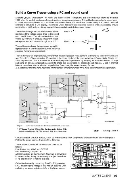
<strong>Build</strong> a <strong>Curve</strong> <strong>Tracer</strong> <strong>using</strong> a <strong>PC</strong> <strong>and</strong> <strong>sound</strong> <strong>card</strong>ZS6KRA recent QEX/QST publication* - or rather the author’s name - caught my eye as he was well known to me since1980 when he started publishing electronic projects in various magazines. This publication described a curve tracerto characterise components such as diodes <strong>and</strong> various linear <strong>and</strong> non-linear devices <strong>using</strong> a <strong>PC</strong> <strong>sound</strong> <strong>card</strong> <strong>and</strong>software to emualate a CRT display. The Device Under Test (DUT) is connected in series with an accurately knownresistor R m = 100Ω <strong>and</strong> a ±10V p-p sinusoidal wave packet applied via a power driver.The current through the DUT is monitored by theresistor <strong>and</strong> the voltage across it fed to the <strong>sound</strong><strong>card</strong> L <strong>and</strong> R inputs. This information is then processedby software to produce a record of sweptvoltage across - <strong>and</strong> current through - the DUT.The oscilloscope display then produces a graphicrepresentation of the voltage <strong>and</strong> current which weanalogue humans can underst<strong>and</strong>.Line in RLine in LR mDUTThere is however an important requirement that measuring system must conform to before we can believe what wesee. The effects of large capacitor AC coupling in the <strong>sound</strong> <strong>card</strong> must be reversed with a software digital filter to geta flat step respnse. This is achieved as a once-off preparatory procedure by applying an accurately known DC step<strong>and</strong> <strong>using</strong> on-screen compensation control to shape the scope trace for amplitude <strong>and</strong> flatness. L <strong>and</strong> R channelbalance control can also be adjusted to perfection. Once done, the system is ready for use.It is suggested that the more inquisitive reader consult the original article for a more detailed technical explanation.* I-V <strong>Curve</strong> Tracing With a <strong>PC</strong>. Dr George R. Steber PhD.Software available on the QEX website. Else from this author.Concentrating on practical aspects, it can be seen that only a few components are required <strong>and</strong> I have designed a<strong>PC</strong>B for the job as shown. (true size 55 x 31,5mm)The <strong>PC</strong> <strong>sound</strong> controls are recommended to be set asfollows:Play: Enable only WAVE <strong>and</strong> OUTPUTRec: Enable only LINE/MIC INAll slider controls set to maximum. Maximum is convenientto remember but it may be necessary to adjust the valuesof R8 <strong>and</strong> R9 down to honour this rule.Calibration is done by connecting 2 <strong>and</strong> 3 of J1, pressingSW1, measuring the voltage at TP1 with an accurate DVM<strong>and</strong> doing on-screen adjustments for a display as shown.WATTS 02-2007 p6
The first screen shows a superposition of slightly over-, under-, <strong>and</strong> ideal compensation. The top middle trace is whatto aim for <strong>and</strong> the amplitude must be = DVM voltage previously measured. The trace at the screen centre must runperfectly along the zero line indicating perfect L-R stereo balance. The control for this is available via the CALIBRATEbutton (top left). The trace is initiated by clicking on START, wait for the trigger indicator to go red <strong>and</strong> pressing thehardware TEST button.Once done, further operation is simple. Connect a DUT, click START <strong>and</strong> a trace will appear. X <strong>and</strong> Y scaling isadjustable <strong>and</strong> the trace can be stored for further reference. There is also a cursor for precise measurements.This is it in a nutshell. Below is my version of the unit that I hook to a dual power supply <strong>and</strong> <strong>sound</strong> <strong>card</strong>. I haveadded an extra switcheable R m of 1k <strong>and</strong> reduced R2 to 1k8 so that a maximum voltage sweep of just on ±10V isavailable when <strong>using</strong> a ±12V DC supply. Variable sweep is also possible <strong>using</strong> the Windows Play Control slider.A further note on <strong>sound</strong> <strong>card</strong> performance is in order. A good wide, flat frequency response is desirable. An extremlyuseful software utility RMAA5.5 is available free from http://audio.rightmark.org/download.shtml. All you need to dois to connect line-out to line-in <strong>and</strong> the software will test some 7 audio parameters:My laptop <strong>sound</strong><strong>card</strong> response (not very suitable)Sound Blaster 24 (balance deliberately offset)WATTS 02-2007 p7