Synchronizing Physiology Data with Associated Video - Biopac
Synchronizing Physiology Data with Associated Video - Biopac
Synchronizing Physiology Data with Associated Video - Biopac

You also want an ePaper? Increase the reach of your titles
YUMPU automatically turns print PDFs into web optimized ePapers that Google loves.
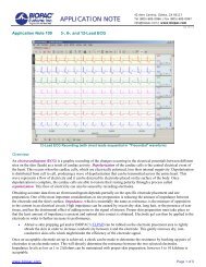
APPLICATION NOTES<br />
42 Aero Camino, Goleta, CA 93117<br />
Tel (805) 685-0066 | Fax (805) 685-0067<br />
info@biopac.com |support@.biopac.com<br />
Application Note 270<br />
<strong>Synchronizing</strong> <strong>Physiology</strong> <strong>Data</strong> Recording <strong>with</strong> <strong>Associated</strong> <strong>Video</strong><br />
Using AcqKnowledge and MP150<br />
Synchronized video coupled to simultaneously recorded physiological variables can increase understanding of test<br />
results. AcqKnowledge software, running under Windows, provides the ability to record a video signal which can be<br />
simultaneously collected <strong>with</strong> other types of time-series data, such as biopotential data (ECG, EEG, EMG, or EOG) or<br />
transducer data (electrodermal activity, force, temperature, pressure, goniometer, accelerometer, strain, etc.).<br />
The key issue when performing simultaneous recording of physiological data and video data is synchronization. Because<br />
the video camera and associated digitizer are separate devices from the MP unit, the data from the video digitizer is only<br />
combined <strong>with</strong> data from the MP unit as they arrive to the AcqKnowledge application running on the computer.<br />
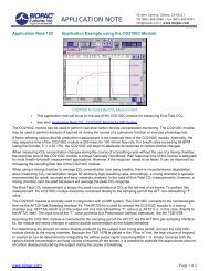
The setup illustrated in this application note can be used to determine the differences in clock rates between the video<br />
digitizer and the MP unit. This difference number, expressed in ppm, can be used to estimate the maximum error<br />
expected when physiological data acquired by the MP unit is compared to simultaneously acquired video data into<br />
AcqKnowledge.<br />
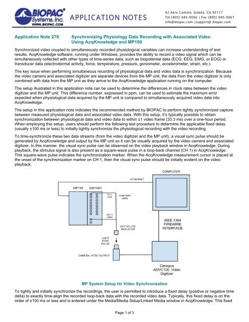
The setup in this application note indicates the recommended method by BIOPAC to perform tightly synchronized capture<br />
between measured physiological data and associated video data. With this setup, it’s typically possible to obtain<br />
synchronization between physiological data and video data to <strong>with</strong>in ±1 video frame (33.3 ms) over a one-hour period.<br />
When employing this setup, users should perform the following test procedure to determine the applicable fixed delay<br />
(usually ±100 ms or less) to initially tightly synchronize the physiological recording <strong>with</strong> the video recording.<br />
To time-synchronize these two data streams (from the video digitizer and the MP unit), a visual sync pulse should be<br />
generated by AcqKnowledge and output by the MP unit so it can be visually acquired by the video camera and associated<br />
digitizer. In this manner, the visual sync pulse can be observed on the video playback window in AcqKnowledge. During<br />
playback, the stimulus signal is also present as a square-wave pulse in a loop-back channel (CH 1) in AcqKnowledge.<br />
This square-wave pulse indicates the synchronization marker. When the AcqKnowledge measurement cursor is placed at<br />
the onset of the synchronization marker on CH 1, then the visual sync pulse should be initially evident on the video<br />
playback.<br />
MP System Setup for <strong>Video</strong> Synchronization<br />
To tightly and initially synchronize the recordings, the user is permitted to introduce a fixed delay (positive or negative time<br />
delta) to exactly time-align the recorded loop-back data <strong>with</strong> the recorded video data. Typically, this fixed delay is on the<br />
order of ±100 ms or less and is entered under the Media/Media Setup/Linked Media window in AcqKnowledge. This fixed<br />
Page 1 of 3
BIOPAC Systems, Inc. <strong>Synchronizing</strong> <strong>Physiology</strong> <strong>Data</strong> Recording <strong>with</strong> <strong>Associated</strong> <strong>Video</strong> www.biopac.com<br />
delay is present because the various software processes operating <strong>with</strong>in AcqKnowledge, the video digitizer and the MP<br />
unit are subject to time execution changes depending on computer type and Ethernet traffic. This fixed delay does not<br />
vary, once determined for a specific computer setup. For applications requiring ±1 second synchronization accuracy or<br />
less, establishing this fixed delay is not necessary and it can be left at its default value of 0 ms.<br />
Three synchronization tests were performed: the first test was for 1,500 seconds, the second test was for 1 hour (3,600<br />
seconds), and the final test was for 24 hours (86,400 seconds).<br />
All tests employed the OUT103 LED indicator, driven from Analog Output 0, <strong>with</strong> a stimulus loop-back cable connected to<br />
CH 1. A periodic pulse train was generated in the AcqKnowledge Stimulus Setup window and output via OUT 0 port on<br />
UIM100C. The OUT 0 port was connected to a 3.5 mm mono splitter. One output of the splitter was set to drive the<br />
OUT103, the other output of the splitter was directed through the loop-back cable to the CH 1 Analog input. CH 1 was<br />
sampled at 1000 Hz, during simultaneous output of the stimulator signal driving both OUT103 and CH 1.<br />
Stimulator Setup Output to Analog Output 0<br />
The ADVC100 (Canopus Technology) – from Grass Valley – video digitizer was used to collect NTSC analog video data<br />
direct to the computer running AcqKnowledge under Windows. The ADVC100 interface was via IEEE1394 (Firewire). The<br />
video data was saved in AcqKnowledge <strong>with</strong> Windows Media <strong>Video</strong> (*.wmv) format.<br />
• WMV formatted files include time-code information and are better suited for holding tight synchronization of video<br />
data over long periods of time.<br />
• <strong>Video</strong> data recorded in AcqKnowledge in Audio <strong>Video</strong> Interleave (*.avi) format is best suited for synchronization of<br />
video data only when audio data is also recorded.<br />
TEST 1 Results—1,500 second acquisition<br />
Camera-sourced video data was observed to be synchronized to the waveform data (stimulus loop-back display<br />
on CH 1) <strong>with</strong>in a maximum delta of 2 frames (±1 frame) from beginning to end of recording. The fixed delay used<br />
in Media/Media Setup/Linked Media was -100 ms.<br />
The fixed delay was adjusted so an equal number of frames were indicated as both slightly ahead and slightly<br />
behind the defined light trigger point, and these time deltas were always less than the time period of one frame<br />
(33.3 ms).<br />
Page 2 of 3
BIOPAC Systems, Inc. <strong>Synchronizing</strong> <strong>Physiology</strong> <strong>Data</strong> Recording <strong>with</strong> <strong>Associated</strong> <strong>Video</strong> www.biopac.com<br />
TEST 2 Results—3,600 second acquisition<br />
Camera-sourced video data was observed to be synchronized to the waveform data (stimulus loop-back display<br />
on CH 1) <strong>with</strong>in a maximum delta of 2 frames (±1 frame) from beginning to end of recording. The fixed delay used<br />
in Media/Media Setup/Linked Media was -100 ms.<br />
The fixed delay was adjusted so an equal number of frames were indicated as both slightly ahead and slightly<br />
behind the defined light trigger point, and these time deltas were always less than the time period of one frame<br />
(33.3 ms).<br />
TEST 3 Results—86,400 second acquisition<br />
Camera-sourced video data was synchronized to the waveform data (stimulus loop-back display) <strong>with</strong>in a<br />
maximum delta of 54 frames (±27 frames) from beginning to end of recording. The fixed delay used in<br />
Media/Media Setup/Linked Media was -100 ms.<br />
The fixed delay was adjusted so an equal number of frames were indicated as both slightly ahead and slightly<br />
behind the defined light trigger point, <strong>with</strong>in the first 3,600 seconds of the recording. These time deltas were<br />
always less than the time period of one frame (33.3 ms), <strong>with</strong>in the first 3,600 seconds of the recording.<br />
After 3,600 seconds had elapsed, it became more evident that there was a very slight difference in the clocking speed<br />
between the MP150 unit and the video digitizer. The following table shows the linear drift in time offset (due to video<br />
digitizer and MP unit clock speed differences) between the video signal and the synchronization marker.<br />
Time (seconds) Offset (ms) <strong>Video</strong> Frame Offset<br />
0 -30 1<br />
1,350 0 0<br />
2,700 +30 1<br />
5,400 +68 2<br />
10,800 +175 5<br />
21,600 +434 13<br />
43,200 +868 26<br />
86,400 +1793 54<br />
The table shows that there is a reasonably linear drift between the video digitizer clock and the MP clock on the order of<br />
1.793 seconds over a 24 hour (86,400 second) period. This translates to a clock speed difference of (1.793/86,400) or 21<br />
ppm. This means that the MP clock and the video digitizer clock are equivalent to each other <strong>with</strong>in 21 ppm, or stated<br />
differently, the ratio between the clock speeds is 1.000021.<br />
These results will be typical for the configuration specified in this application note. The ADVC100 video digitizer adheres<br />
to the IEEE 1394 interface standard and will provide considerably more accurate timing than a typical USB (web) camera.<br />
Furthermore, the IEEE 1394 interface will provide higher reliability for data transfer to the host computer, <strong>with</strong> far less<br />
propensity to drop frames, as compared to the USB interface.<br />
Page 3 of 3