13946: 295HFSA7 & 295HFSA8 Dual Siren Control Head - Whelen ...
13946: 295HFSA7 & 295HFSA8 Dual Siren Control Head - Whelen ...
13946: 295HFSA7 & 295HFSA8 Dual Siren Control Head - Whelen ...

Create successful ePaper yourself
Turn your PDF publications into a flip-book with our unique Google optimized e-Paper software.
Installation: Amplifier<br />
1. Locate a suitable mounting location for the amplifier. The vertical wall<br />
between the trunk and the passenger compartment is often a good<br />
choice and is the method discussed in this manual.<br />
2. Be sure that the amplifier fits properly and does not interfere with any<br />
parts of the trunk lid or seat back.<br />
3. Position the amplifier on the proposed mounting location. Using an<br />
awl or other suitable tool, scribe the mounting surface where the<br />
mounting holes are to be drilled.<br />
CAUTION! As mounting the amplifier will require drilling, it is<br />
absolutely necessary to make sure that no other vehicle components<br />
could be damaged by the drilling process. If any vehicle component<br />
could suffer any potential harm, select a different mounting location.<br />
4. Carefully drill the mounting holes using a drill bit sized for a #10 sheet<br />
metal screw.<br />
5. Using the supplied #10 x 3/4” sheet metal screws, secure the remote<br />
amplifier to the vertical trunk wall.<br />
Wiring<br />
Connecting to Power:<br />
1. Using appropriately sized wire, extend the RED and BLACK wires<br />
from the Main Power Connector, through the firewall and into the<br />
engine compartment (refer to the Wire Gage Calculation Chart<br />
located on the last page of this manual to determine the proper wire<br />
size for your application).<br />
2. Follow the factory wiring harness towards your vehicle’s battery.<br />
WARNING! All customer supplied wires that connect to the positive<br />
terminal of the battery must be sized to supply at least 125% of the<br />
maximum operating current and FUSED at the battery to carry that<br />
load. DO NOT USE CIRCUIT BREAKERS WITH THIS PRODUCT!<br />
3. Install a user supplied 20A fuse block on the end of the RED wire.<br />
Connect the fuse block to the battery using no more than 2 feet of<br />
wire. Do not install the fuse into the fuse holder yet!<br />
4. Connect the BLACK wire directly to the NEGATIVE battery terminal.<br />
Connecting to your Speaker(s):<br />
1. Route the ORANGE, and BROWN wires from both <strong>Siren</strong> Connector<br />
#1 and <strong>Siren</strong> Connector #2 along the factory wiring harness towards<br />
your speakers.<br />
2. Connect the ORANGE wire from <strong>Siren</strong> Connector #1 to the<br />
POSITIVE (+) terminal on speaker #1. Connect the ORANGE wire<br />
from <strong>Siren</strong> Connector #2 to the POSITIVE (+) terminal on speaker<br />
#2.<br />
3. Connect the BROWN wire from <strong>Siren</strong> Connector #1 to the<br />
NEGATIVE (-) terminal on speaker #1. Connect the BROWN wire<br />
from <strong>Siren</strong> Connector #2 to the NEGATIVE (-) terminal on speaker<br />
#2.<br />
Hands-Free <strong>Siren</strong> (optional):<br />
Refer to the wiring diagram for all wiring information for this optional<br />
connection.<br />
Radio Rebroadcast (optional):<br />
The two (2) BLUE wires are used to connect your two-way radio’s external<br />
speaker for radio rebroadcast. This is an optional connection and will not<br />
effect the other operations.<br />
Note: Radio rebroadcast will NOT work with amplified remote<br />
speakers! If your remote speaker is amplified (I.E.: contains a power<br />
amp circuit in the speaker assembly), do not enable the radio<br />
rebroadcast feature.<br />
Installation will be complete after a 20A fuse has been installed in the Main<br />
Power Connector fuse block. Now inspect the fuses at the back of the<br />
amplifier and at the battery. If either of these fuses are blown, carefully<br />
inspect all of the circuit wires and make sure they are wired correctly.<br />
Replace the blown fuses with ones of an identical amp rating. If these<br />
fuses blow after installation or activation, contact <strong>Whelen</strong> Engineering<br />
Technical Support.<br />
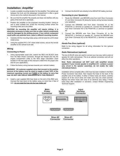
Main<br />
Power<br />
Connector<br />
Dip<br />
Switch<br />
Bank<br />
Input<br />
Harness<br />
Connector<br />
On 1 2 3 4 5 6 7 8<br />
<strong>Siren</strong> #2<br />
Connector<br />
<strong>Siren</strong> #1<br />
Connector<br />
Page 3