GRAIN STIR-ATOR - David Manufacturing Co.
GRAIN STIR-ATOR - David Manufacturing Co.
GRAIN STIR-ATOR - David Manufacturing Co.

You also want an ePaper? Increase the reach of your titles
YUMPU automatically turns print PDFs into web optimized ePapers that Google loves.
OWNER’S MANUAL<br />
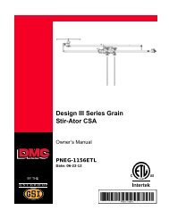
DESIGN III SERIES<br />
<strong>GRAIN</strong><br />
<strong>STIR</strong>-<strong>ATOR</strong><br />
PNEG-1156<br />
Date: 09-20-06<br />
PNEG-1156
Patent Notice<br />
The Kalke-Murphy Grain Stir-Ator is manufactured under exclusive license for United States Patent Numbers<br />
3,580,549 and 4,374,621. Infringing manufacturers, sellers, and users are subject to prosecution in<br />
the Federal <strong>Co</strong>urts.<br />
<strong>STIR</strong>-<strong>ATOR</strong> is a registered trade-mark of <strong>David</strong> <strong>Manufacturing</strong> <strong>Co</strong>mpany.
DIII Stir-Ator<br />
TABLE OF CONTENTS<br />
Safety ............................................................................................................................ 4<br />
Decal Placement .......................................................................................................... 11<br />
Final Inspection Check List .......................................................................................... 13<br />
Overall Dimension Chart ............................................................................................... 14<br />
Auger Length & Dimension (Drawing A) ....................................................................... 15<br />
Shipping Weights ......................................................................................................... 16<br />
Installation<br />
Track ..................................................................................................................... 17<br />
Suspension Chain .................................................................................................. 19<br />
Switch Box ............................................................................................................ 20<br />
Frame Rails ........................................................................................................... 21<br />
Trolley.................................................................................................................... 22<br />
Yokes .................................................................................................................... 25<br />
Swing Arm ............................................................................................................. 27<br />
Junction Box .......................................................................................................... 27<br />
Trolley Drive Arm to Cable ...................................................................................... 29<br />
Center Suspension System ................................................................................... 30<br />
Track Gear Motor................................................................................................... 31<br />
Leveler Disk ........................................................................................................... 31<br />
Offset Auger Option ............................................................................................... 32<br />
Lifting Stir-Ator ....................................................................................................... 33<br />
Suspension Chain .................................................................................................. 35<br />
Installing Stir-Ator Auger ........................................................................................ 37<br />
Management and Maintenance<br />
Outboard Auger Tilt ................................................................................................ 40<br />
Cable Tension ........................................................................................................ 41<br />
Trolley Drive Link ................................................................................................... 41<br />
Mercury Switch...................................................................................................... 42<br />
Safety Shutoff Switch ............................................................................................ 42<br />
Operation<br />
Operations of Design III .......................................................................................... 43<br />
Start-Up Procedure in a Full Bin ............................................................................. 44<br />
Track Unit Drive Sprocket....................................................................................... 44<br />
Stir-Guard .............................................................................................................. 45<br />
Storage .................................................................................................................. 46<br />
Drying Chart .......................................................................................................... 47<br />
Design III Trouble Shooting Guide ................................................................... 48 - 49<br />
Parts List<br />
Track Unit .............................................................................................................. 51<br />
Switch Boxes and Suspensions (Drawing B) ......................................................... 52<br />
Yoke ...................................................................................................................... 54<br />
Single Auger Trolley ............................................................................................... 56<br />
Double Auger Trolley .............................................................................................. 58<br />
Triple Auger Trolley ................................................................................................ 60<br />
Gear Motor 502A0040 - 230 Volt ............................................................................ 62<br />
Gear Motor 502A0045 - 440 Volt ............................................................................ 63<br />
Stir-Guard Option 230 ............................................................................................ 64<br />
Stir-Guard Option 440 ............................................................................................ 65<br />
Offset Auger Option ............................................................................................... 66<br />
Wiring Diagrams<br />
Single Phase-230V ................................................................................................ 67<br />
Three Phase-230V ................................................................................................. 68<br />
Three Phase-440V ................................................................................................. 69<br />
Three Phase-380V ................................................................................................. 70<br />
3
Safety<br />
PNEG-1156 DIII Stir-Ator<br />
SAFETY GUIDELINES<br />
This manual contains information that is important for you, the owner/operator, to know and understand.<br />
This information relates to protecting personal safety and preventing<br />
equipment problems. It is the responsibility of the owner/operator to inform anyone<br />
operating or working in the area of this equipment of these safety guidelines. To help you<br />
recognize this information, we use the symbols that are defined below.<br />
Please read the manual and pay attention to these sections. Failure to read this manual<br />
and it’s safety instructions is a misuse of the equipment and may lead to serious injury or death.<br />
This is the safety alert symbol. It is used to alert you<br />
to potential personal injury hazards. Obey all<br />
safety messages that follow this symbol to avoid possible injury or<br />
death.<br />
DANGER indicates an imminently hazardous situation which, if not<br />
avoided, will result in death or serious injury.<br />
WARNING indicates a potentially hazardous situation which, if not<br />
avoided, could result in death or serious injury.<br />
CAUTION indicates a potentially hazardous situation which, if not avoided,<br />
may result in minor or moderate injury.<br />
CAUTION used without the safety alert symbol indicates a potentially<br />
hazardous situation which, if not avoided, may result in property<br />
damage.<br />
NOTE indicates information about the equipment that you should pay<br />
special attention to.<br />
4
PNEG-1156 DIII Stir-Ator<br />
Safety<br />
FOLLOW SAFETY INSTRUCTIONS<br />
Carefully read all safety messages in this manual<br />
and on your machine safety signs. Keep signs in<br />
good condition. Replace missing or damaged<br />
safety signs. Be sure new equipment components<br />
and repair parts include the current safety<br />
signs. Replacement safety signs are available<br />
from the manufacturer.<br />
Learn how to operate the machine and how to<br />
use controls properly. Do not let anyone operate<br />
without instruction.<br />
Keep your machinery in proper working condition.<br />
Unauthorized modifications to the machine<br />
may impair the function and/or safety and affect<br />
machine life.<br />
If you do not understand any part of this manual<br />
and need assistance, contact your dealer.<br />
STAY CLEAR OF ROTATING PARTS<br />
Entanglement in rotating augers will cause<br />
serious injury or death.<br />
Keep all shields and covers in place at all times.<br />
Wear close fitting clothing. Stop and lock out<br />
power source before making adjustments,<br />
cleaning, or maintaining equipment.<br />
OPERATE MOTOR PROPERLY<br />
Do not operate electric motor equipped units<br />
until motors are properly grounded.<br />
Disconnect power on electrical driven units<br />
before resetting motor overloads.<br />
Do not repetitively stop and start the drive in<br />
order to free a plugged condition. Jogging the<br />
drive in this type of condition can damage the<br />
equipment.<br />
5
Safety<br />
PNEG-1156 DIII Stir-Ator<br />
PRACTICE SAFE MAINTENANCE<br />
Always lockout power source before servicing<br />
equipment.<br />
Understand service procedures before doing<br />
work. Keep area clean and dry.<br />
Never lubricate, service, or adjust machine while<br />
it is in operation. Keep hands, feet, and clothing<br />
from rotating parts.<br />
Keep all parts in good condition and properly<br />
installed. Fix damage immediately. Replace<br />
worn or broken parts. Remove any build up of<br />
grease, oil, or debris.<br />
AVOID FALLS<br />
When working using ladders be sure to have<br />
rubber pads or some other method of keeping<br />
the ladder from slipping on the bin or silo floor.<br />
Because the Stir-Ator is suspended from chains<br />
in the center, be cautious of positioning ladder<br />
against the Stir-Ator. The Stir-Ator can move or<br />
swing from the weight of a person climbing on<br />
the ladder.<br />
Also, when setting a ladder against the Stir-Ator,<br />
a vise grip or some other type of tie down should<br />
be used in the front and back of the track drive<br />
unit. This keeps the Stir-Ator from rolling or<br />
sliding around the bin while service work is being<br />
performed.<br />
Use<br />
Ladders<br />
Safely.<br />
During heavy service work, such as removing<br />
auger drive, electric motors, or replacing electrical<br />
swivel, tying the ladder to the main frame or<br />
some other solid component is advised.<br />
6
PNEG-1156 DIII Stir-Ator<br />
Safety<br />
PREPARE FOR EMERGENCIES<br />
Be prepared if fire starts.<br />
Keep a first aid kit and fire extinguisher handy.<br />
Keep emergency numbers for doctors, ambulance<br />
service, hospital, and fire department near<br />
your telephone.<br />
WEAR PROTECTIVE CLOTHING<br />
Wear close fitting clothing and safety equipment<br />
appropriate to the job.<br />
Eye Protection<br />
Safety glasses should be worn at all times to<br />
protect eyes from debris.<br />
Wear gloves to protect your hands from sharp<br />
edges on plastic or steel parts.<br />
A respirator may be needed to help prevent<br />
breathing potentially toxic fumes and dust.<br />
Gloves<br />
Wear hard hat and steel toe boots to help<br />
protect your head and toes from falling debris.<br />
Steel Toe<br />
Boots<br />
Respirator<br />
Hard Hat<br />
7
Safety<br />
PNEG-1156 DIII Stir-Ator<br />
BE A SAFE OPER<strong>ATOR</strong><br />
Before operating, familiarize yourself with the machine. It will help you to operate your<br />
Design III Stir-Ator more efficiently, with better quality returns to you.<br />
1. Read and understand the Owner’s Manual.<br />
2. Keep all safety shields in place.<br />
3. Disconnect all electrical power prior to inspecting, servicing, lubricating, or adjusting<br />
the equipment.<br />
4. Keep hands, feet, and clothing from moving parts while in operation. NEVER stand or<br />
sit on unit while in operation.<br />
5. To avoid serious injury or death, stay away from the unit and make sure everyone else<br />
is clear of the Stir-Ator before starting or operating the unit.<br />
6. Do NOT operate the Stir-Ator unless shut-off chain has been properly installed and<br />
adjusted.<br />
7. Never enter the bin while the Stir-Ator is in operation.<br />
8. Before operating your Stir-Ator, familiarize yourself with the machine. Know how to<br />
operate and adjust it. This will enable you to get maximum efficiency from the equipment,<br />
plus better quality grain as a result.<br />
9. When starting the Stir-Ator in a full bin of grain, care should be exercised because the<br />
augers can be stuck in the grain, causing damage to the Stir-Ator, or to the bin.<br />
10. Operating the Stir-Ator during bin unloading can be beneficial to the unloading process<br />
as well as prevent auger damage.<br />
11. BURYING THE UNIT WILL DAMAGE THE BIN AND WILL VOID YOUR DESIGN III<br />
WARRANTY.<br />
12. DO NOT OPERATE DESIGN III <strong>STIR</strong>-<strong>ATOR</strong> IN AN EMPTY BIN. To test the unit in an<br />
empty bin, make sure no one is inside the bin, then turn power “on" and “off" immediately<br />
from the outside of the bin. DO NOT let it run in an empty bin. Damage to Stir-<br />
Ator and bin can result.<br />
13. All electrical hook-ups should be in accordance to the National Electrical <strong>Co</strong>de. Be<br />
sure equipment and bins are properly grounded.<br />
14. When not operating the unit for extended periods of time, or in some cases while<br />
emptying the bin, it may be best to position the trolley at the bin wall to eliminate<br />
possible Stir-Ator or bin damage.<br />
8
PNEG-1156 DIII Stir-Ator<br />
Safety<br />
SAFETY FIRST PAYS<br />
Read and heed all safety reminders listed below.<br />
To perform service work on a stirring device installed in a bin:<br />
1. Turn off and lockout power source.<br />
2. A safe ladder should be used.<br />
3. When setting a ladder against the Stir-Ator, a vise grip or some type of tie down<br />
should be used in the front and back of the track drive unit. This keeps the Stir-Ator<br />
from rolling or sliding around the bin while service work is being performed.<br />
4. Because the Stir-Ator is suspended from chains in the center, care has to be exercised<br />
whenever a ladder is positioned against the Stir-Ator. The Stir-Ator can move<br />
or swing from the weight of a person climbing on the ladder.<br />
5. Climbing out on the main frame from either a ladder or roof manhole should NOT be<br />
attempted. The Stir-Ator can swing, causing a fall.<br />
6. During heavy service work, such as removing auger drive, electric motors, or replacing<br />
electrical swivel, tying the ladder to the main frame or to some other solid component<br />
is advised.<br />
7. Be sure to have rubber pads or some method of keeping the ladder from slipping on<br />
the bin or silo floor. Slipping can cause a fall or serious accident.<br />
8. Do NOT climb Stir-Ator down augers to make adjustments or repairs. Slipping<br />
could cause falling, bodily injury, or both.<br />
9. If an unusual amount of service work is to be performed on a Stir-Ator, removing the<br />
augers and lowering the unit onto saw horses may be the safest way to repair the<br />
unit.<br />
10. Caution needs to be exercised when using a ladder to perform service work in a<br />
partially filled grain bin. The ladder can sink into the grain, allowing it to fall.<br />
9
Safety<br />
PNEG-1156 DIII Stir-Ator<br />
Operator Qualifications<br />
A. The User/Operator must be competent and experienced to operate this equipment. Anyone who works with or<br />
around this equipment must have good common sense in order to be qualified. These persons must also know and<br />
meet all other qualifications, such as:<br />
1. Any person who has not read and/or does not understand all operation and safety<br />
procedures is not qualified to operate this system.<br />
2. Certain regulations apply to personnel operating power machinery. Personnel under<br />
the age of 18 years may not operate power machinery, including augers. It is your<br />
responsibility, as owner and/or supervisor, to know what these regulations are in your<br />
area or situation.<br />
3. Unqualified or incompetent persons are to remain out of the work area.<br />
4. O.S.H.A. (Occupational Safety & Health Administration) regulations state:<br />
"At the time of initial assignment and at least annually thereafter, the employer shall<br />
instruct every employee in the safe operation and servicing of all equipment with<br />
which the employee is, or will be involved." (Federal Occupational Safety & Health<br />
Standards for Agriculture. Subpart D, Section 19287.57 (a) (6).<br />
B. As a requirement of OSHA, it is necessary for the employer to train the employee in the safe operating and safety<br />
procedures for this equipment. We included this sign-off sheet for your convenience and personal record keeping. All<br />
unqualified persons are to stay out of the work area at all times. It is strongly recommended that another qualified<br />
person who knows the shutdown procedure is in the area in the event of an emergency. A person who has not read<br />
this manual and doesn’t understand all operating and safety instructions, is not qualified to operate this machine.<br />
DATE EMPLOYER'S SIGNATURE EMPLOYEE'S SIGNATURE<br />
10
PNEG-1156 DIII Stir-Ator<br />
Safety<br />
THE DECALS SHOWN ON THIS PAGE MUST BE DISPLAYED AS SHOWN<br />
Replacements are available upon request. Write to the following address:<br />
<strong>David</strong> <strong>Manufacturing</strong>. <strong>Co</strong>., 1004 E. Illinois St., Assumption, IL 62510<br />
Please note:1. The decals on this page are not actual size.<br />
2. Keep all decals wiped clean at all times.<br />
3. All decals must be replaced if they are destroyed,<br />
missing, painted over or can no longer be read.<br />
KEEP HANDS OUT!<br />
DC-889<br />
DC-889<br />
Both sides of swivel box<br />
plus junction box cover.<br />
1067022<br />
1067022<br />
Top of gear motor track frame.<br />
1067021<br />
Both sides of bottom motor mounting rail in<br />
trolley and both sides of optional offset.<br />
KEEP CLEAR OF ROTATING PARTS!<br />
1067021<br />
DC-GBC-1A &<br />
DC-GBC-1S<br />
Should be located<br />
at any bin entry so<br />
it can be seen<br />
and read easily.<br />
Rotating flighting will<br />
kill or dismember.<br />
Flowing material will<br />
trap and suffocate.<br />
Crusted material will<br />
collapse and suffocate.<br />
Keep clear of all augers.<br />
DO NOT ENTER this bin!<br />
If you must enter the bin:<br />
1. Shut off and lock out all power.<br />
2. Use a safety harness and safety line.<br />
3. Station another person outside the bin.<br />
4. Avoid the center of the bin.<br />
5. Wear proper breathing equipment or respirator.<br />
Failure to heed these<br />
warnings will result in<br />
serious injury or death.<br />
DC-GBC-1A<br />
11
Safety<br />
PNEG-1156 DIII Stir-Ator<br />
Rotating flighting will<br />
kill or dismember.<br />
Flowing material will<br />
trap and suffocate.<br />
Crusted material will<br />
collapse and suffocate.<br />
Keep clear of all augers.<br />
DO NOT ENTER this bin!<br />
If you must enter the bin:<br />
1. Shut off and lock out all power.<br />
2. Use a safety harness and safety line.<br />
3. Station another person outside the bin.<br />
4. Avoid the center of the bin.<br />
5. Wear proper breathing equipment or respirator.<br />
Failure to heed these<br />
warnings will result in<br />
serious injury or death.<br />
DC-GBC-1A<br />
This decal is to be located so it can be easily seen and read at any<br />
entry point into the bin or silo.<br />
12
PNEG-1156 DIII Stir-Ator<br />
Safety<br />
FINAL INSPECTION CHECK LIST<br />
1. READ THE <strong>STIR</strong>-<strong>ATOR</strong> OWNER’S MANUAL BEFORE INSTALLATION. MANY SERVICE<br />
PROBLEMS WILL BE ELIMINATED IF <strong>STIR</strong>-<strong>ATOR</strong> IS PROPERLY INSTALLED.<br />
2. Is there at least 10-1/4" clearance from the center of the track to the lowest part of the roof<br />
and roof braces.<br />
3. Are the track splices correctly installed? <strong>Co</strong>nsult the diagrams in the owner’s manual.<br />
4. Is the trolley installed correctly (drive arm pointing toward the center of the bin)?<br />
5. Are the bolt heads holding the yoke end to the frame on the inside on the frame rails, and<br />
the cotter key spread on the pivot tube?<br />
6. Is the suspension bar properly hung, LEVEL, with the end loops down, is the 1/2" x 2" bolt<br />
holding suspension bar tightly secured? Is the lock nut on tee fitted properly?<br />
7. Is the suspension bar so positioned that the bin “S" hook, to which the shut-off chain is<br />
attached, is at a right angle to the switch box chain, as shown in Figure 3-A and<br />
Photos 4A-4<strong>Co</strong>n page 19-20? BE SURE THE POWER CORD HAS MORE SLACK THAN THE<br />
SHUT-OFF CHAIN, or the power cord could be torn out of the switch box if the Design III should<br />
malfunction and engage the shut-off.<br />
8. Is the frame of the Design III about 1" higher at the center of the bin for each 18' of bin<br />
diameter?<br />
9. Are augers 3 inches off the drying floor at bin wall? (See Photo 17A on page 37.)<br />
10. Were the augers deburred with a file? Were the clamp bolts torqued to 140 foot pounds?<br />
Was the roll pin installed correctly?<br />
11. Did you note the instruction NOT to weld flighting at the top end of the auger?<br />
12. Are you sure that the electrician connected the black and white wires to the 230 volt<br />
terminals in the operating switch, and the green wire to the ground? See Wiring Diagram.<br />
BE SURE BIN IS GROUNDED.<br />
13. Are you keeping a record of the serial number for each owner?<br />
14. Did you make sure that the owner received and signed for his OWNER’S MANUAL, and<br />
was instructed that reading and understanding the manual will help immensely at drying time?<br />
15. Did you install the safety decals on the inside& outside of the walk-in door and the manhole<br />
cover?<br />
13
Assembly & Installation<br />
PNEG-1156 DIII Stir-Ator<br />
DESIGN III <strong>STIR</strong>-<strong>ATOR</strong> OVERALL DIMENSIONS<br />
WHEELS JUST TOUCH BENDS IN<br />
RAILS WHEN TROLLEY IN<br />
MAXIMUM INBOARD POSITION.<br />
THE INBOARD RAIL END MUST BE 1-1/2 INCHES HIGHER<br />
THAN THE OUTBOARD END FOR BINS UP TO 30 FEET AND<br />
2 INCHES HIGHER FOR BINS 36 FEET AND OVER.<br />
14
PNEG-1156 DIII Stir-Ator<br />
Assembly & Installation<br />
15
Assembly & Installation<br />
PNEG-1156 DIII Stir-Ator<br />
DESIGN III STANDARD EQUIPMENT SHIPPING WEIGHTS<br />
Stir-Ator weights and auger downpull are two factors to take into consideration when<br />
determining the extra stress that is placed on the drying bin wall and roof.<br />
For total weight, add Chart 1 and Chart 2 weights together.<br />
Chart 1<br />
Stir-Ator Shipping Weights<br />
Bin Size Single Auger Double Auger Triple Auger<br />
18' 625 770 ---------<br />
21' 663 808 1030<br />
24' 700 844 1070<br />
27' 737 882 1112<br />
30' 775 920 1150<br />
33' 812 960 1200<br />
36; 867 1014 1265<br />
40' 905 1052 1306<br />
42' 940 1088 1345<br />
48' 1050 1200 1500<br />
Additional Weight With Optional Equipment<br />
2 HP, single phase motor 33# per motor<br />
2 HP, three phase motor 13# per motor<br />
18' augers 5# per auger<br />
20' augers 10# per auger<br />
Chart 2<br />
Auger Downpull in Pounds<br />
Initial Startup - Wet Grain<br />
16' auger 14' grain 368# per auger<br />
18' auger 16' grain 390# per auger<br />
20' auger 18' grain 410 # per auger<br />
Auger Downpull in Pounds<br />
Normal Operation - Wet Grain<br />
16' auger 14' grain 207# per auger<br />
18' auger 16' grain 241# per auger<br />
20' auger 18' grain 300# per auger<br />
16
PNEG-1156 DIII Stir-Ator<br />
Assembly & Installation<br />
1. INSTALLATION OF THE<br />
DESIGN III <strong>STIR</strong>-<strong>ATOR</strong><br />
PRIOR TO ASSEMBLY AND INSTALLATION<br />
CONSULT THE BIN ERECTION MANUAL OR<br />
MANUFACTURER FOR ANY SPECIAL UNIT<br />
HANGING OR SUPPORT LOCATIONS.<br />
A. Before starting to assemble the bin, the<br />
DESIGN III Stir-Ator, less the augers, should<br />
be laid in the center of the bin floor. See<br />
Photo 1. The top ring of the metal bin is<br />
then assembled in the usual way.<br />
Photo 1<br />
2. TRACK INSTALLATION<br />
5/16" x 1" Bolt<br />
The wall track has two different hole spacing:<br />
18-15/16" on the single and double auger<br />
units and 12-5/8" on the triple auger units.<br />
(See Figure 2)<br />
3-Hole <strong>Co</strong>nnector<br />
5/16" x 3" Bolt<br />
Track<br />
A. The track is installed 10-1/4" distance<br />
from the eave of the bin to the center line<br />
of the track. Bins with steeply pitched or<br />
domed roofs may allow the 10-1/4"<br />
distance to be reduced; roofs with low or<br />
flat profiles may require more clearance.<br />
Reinforcements for the roof or roof ladder<br />
which might interfere with the movement<br />
of the Stir-Ator should be trimmed. See<br />
Drawing A on page 15. If this cannot be<br />
done, the 10-1/4" distance from the eave<br />
to the track bolt center line must be increased<br />
proportionately.<br />
B. The Stir-Ator wall track is installed as<br />
follows:<br />
1.) Fasten 3-hole connector to track using<br />
a 5/16" x 1" bolt through the 1st hole.<br />
(This bolt does not go through bin.)<br />
Photo 2A<br />
2.) 5/16" holes for the track bolts should be<br />
drilled or punched in the bin wall progressively<br />
around the bin 10-1/4" from the eave.<br />
Start with the double hole end of a track<br />
section, then drill or punch a hole through the<br />
bin wall at the second hole location. Attach<br />
the track piece to the wall using a 5/16"x<br />
3"bolt. The bolt should go through the track,<br />
3-hole connector, track bracket, and bin wall.<br />
Fasten with a cup washer and hex nut.<br />
3.) Then, using the hole in the track as a<br />
guide drill or punch the next hole and install<br />
an additional track bracket and bolt, repeating<br />
this procedure around the bin. Tighten<br />
bolts as you go. See Photos 2A, 2B, 2C<br />
and Figure 2.<br />
17
Assembly & Installation<br />
PNEG-1156 DIII Stir-Ator<br />
3-Hole <strong>Co</strong>nnecting Bracket<br />
Single and Double Track Layout (Not to Scale)<br />
5/16" x 3" Bolt<br />
5/16" x 1" Bolt<br />
18-15/16"<br />
Spacing<br />
FIGURE 2<br />
3-Hole <strong>Co</strong>nnecting Bracket<br />
Track Bracket<br />
Triple Track Layout (Not to Scale)<br />
5/16" x 3" Bolt<br />
5/16" x 1" Bolt<br />
12-5/8"<br />
Spacing<br />
Track Bracket<br />
If upon making the complete circuit of the bin and<br />
the last section required is less than 3' in length,<br />
shorten the length of the preceding piece so that<br />
a 3' or longer section can be used. There should<br />
be slightly more material than required.<br />
5/16" x 3" Bolt 5/16" x 3" Bolt<br />
Track<br />
C. The end of the last section should be cut off so<br />
as to fit snugly against the starting end of the<br />
first length, and a 5/16" hole drilled about 5/8"<br />
from the cut-off end. All track joints should be<br />
aligned as smoothly as possible - any misalignment<br />
should be corrected by grinding or<br />
filing and bending if necessary. See Drawing<br />
A on page 15 or Photo 2B.<br />
D. Because the Stir-Ator auger runs close to the<br />
bin wall, no inside wall ladder can be used.<br />
A portable ladder is advised and can be obtained<br />
from your dealer. The closer the Stir-<br />
Ator auger runs to the bin wall, the less chance<br />
of grain spoilage. Drying in cold weather can<br />
require the use of wall liners or air tubes to<br />
minimize bin wall spoilage. (Skid plates should<br />
be put on all walk-in doors that extend into the<br />
bin over 2-1/2".)<br />
Track Bracket<br />
Photo 2B<br />
5/16" x 1" Bolt<br />
After the wall track is installed, check clearance<br />
between the track and bin sheet splice bolts.<br />
Long bolts may catch on Stir-Ator track wheel or<br />
pivot pin on track unit. To alleviate this problem,<br />
cut off the bolts OR reverse them. See Photo 2C.<br />
Bin Sheet<br />
Splice Bolts<br />
Photo 2C<br />
Track Wheel<br />
18
PNEG-1156 DIII Stir-Ator<br />
Assembly & Installation<br />
3. SUSPENSION CHAINS<br />
A. The bin roof is then assembled and the<br />
suspension chains are dropped through the<br />
fill-hole. Two chains are used on the<br />
Single and Double auger units and<br />
three on the Triple Auger Units. Space<br />
the suspension hooks equally apart around<br />
the center fill-hole collar, placing them in<br />
reference to the manhole where the shut-off<br />
switch box is to be located. Place chians<br />
through hole and then slide chain down into<br />
slot. See Figure 3-A & 3-B and Photo 3.<br />
A hole in the suspension hooks is provided<br />
if bolting the hooks in position is desired.<br />
Suspension Hook<br />
Photo 3<br />
Do not use the bolt in the suspension hook to<br />
support the entire unit. The outside end of<br />
stir-ator should be supported by the track.<br />
VIEWED FROM TOP OF BIN<br />
FIGURE 3-A<br />
Suspension<br />
Chain<br />
Bolt<br />
Optional<br />
STRAIGHT BAR<br />
FIGURE 3-B<br />
2-PIECE T-BAR<br />
Side<br />
View<br />
Front<br />
View<br />
Suspension Hook<br />
Slot<br />
Single & Double<br />
Auger Spacing of<br />
Suspension Hooks<br />
Triple Auger<br />
Spacing of<br />
Suspension Hooks<br />
19
Assembly & Installation<br />
PNEG-1156 DIII Stir-Ator<br />
4. SWITCH BOX<br />
A. Install safety switch shut-off switch box and<br />
box brace to bin roof above the manhole<br />
opening. See Drawing A, page 15 for<br />
recommended mounting height.<br />
Switch Box<br />
Brace<br />
Mount the switch box using the mounting<br />
hardware provided, refer to Drawing B,<br />
page 42 for size and description of appropriate<br />
hardware and installation for each<br />
box. See Photos 4A & 4B.<br />
B. Fasten shut-off support chain(s) to bin roof<br />
using existing roof bolts and 5/16" flat<br />
washer and hex nut. Support chains should<br />
be equally spaced between switch box and<br />
center of the bin. See Photo 4C or Drawing<br />
A on page 15.<br />
Switch Box<br />
Photo 4A<br />
Support<br />
Chains<br />
Photo 4B<br />
Mounting the box lower than the minimum<br />
recommended height could cause the box to<br />
be caught by the Stir-Ator as it moves around<br />
the bin, causing possible damage or serious<br />
electrical shock.<br />
Shut-Off<br />
Chain<br />
Photo 4C<br />
Above: Shut-off<br />
support chains<br />
spaced evenly.<br />
Support<br />
Chain<br />
Right: Closeup of<br />
support chain<br />
attached to bin roof.<br />
Shut-Off<br />
Chain<br />
Photo 4D<br />
20
PNEG-1156 DIII Stir-Ator<br />
Assembly & Installation<br />
5. FRAME RAILS<br />
A. To assemble the DESIGN III Stir-Ator, place<br />
frame rails on two saw horses and remove<br />
the two 5/16" bolts holding the frame rails<br />
together, spacing them approximately eight<br />
inches. See Photos 5A.<br />
B. FOR SINGLE AUGER UNITS: Bolt inboard<br />
frame end to frame rails using six 3/8" x 1"<br />
carriage bolts, 3/8" lock washers and hex<br />
nuts. See Photo 5B.<br />
Frame Rails<br />
LOCATE BOLT HEADS TO INSIDE OF<br />
FRAME RAILS. (See Photo 5B)<br />
C. FOR DOUBLE AND TRIPLE AUGER<br />
UNITS: Bolt outboard frame end and track<br />
unit assembly to the frame rails using six<br />
3/8" x 1" carriage bolts, 3/8" lock washers<br />
and hex nuts. (See Photo 5E)<br />
SINGLE AUGER<br />
Photo 5A<br />
3/8" x 1"Carriage Bolts<br />
D. The outboard frame end has two pivot<br />
positions for either 1-1/2 or 2 HP units. The<br />
pivot position is stamped on top of the pivot<br />
clevis and this must be the same as the<br />
trolley HP being used. If the stamp cannot<br />
be read, then go by the position of the pivot<br />
bar. If the pivot bar is on bottom it is set for<br />
1-1/2 HP and if the pivot bar is on top, it is<br />
set for 2 HP. See Photos 5C and 5D.<br />
Inboard Frame End<br />
Frame Rails<br />
Photo 5B<br />
DOUBLE & TRIPLE AUGERS<br />
3/8" x 1"Carriage Bolt<br />
Pivot<br />
Clevis<br />
1-1/2 HP<br />
Stamp<br />
Pivot<br />
Bar on<br />
Bottom<br />
Pivot<br />
Clevis<br />
2HP<br />
Stamp<br />
Pivot Bar<br />
on Top<br />
Pivot Bar<br />
Pivot Clevis<br />
Outboard Frame End<br />
Photo 5C<br />
Photo 5D<br />
Photo 5E<br />
21
Assembly & Installation<br />
PNEG-1156 DIII Stir-Ator<br />
6. TROLLEY<br />
Trolley<br />
Assembly<br />
36' and larger double auger trolleys will require<br />
the hold-down rods to be moved to the bottom<br />
hole position. This is done by removing the<br />
cotter pin and pulling the rod out and reinserting<br />
it in the bottom holes. Refer to Photo 6H for<br />
proper location of the hold-downs.<br />
A. Place trolley on frame with the junction<br />
box toward center of the bin. Single<br />
auger trolley is placed on the frame rails<br />
from the outboard end and double and<br />
triple auger from the inboard end. See<br />
Photos 6A.<br />
FOR SINGLE AUGER UNITS: Bolt<br />
outboard frame end and track unit<br />
assembly to the frame rails using six<br />
3/8" x 1" carriage bolts, 3/8" lock<br />
washers and hex nuts. See Photo 6B.<br />
Trolley Wheels<br />
Photo 6A<br />
Outboard Frame End<br />
Pivot Clevis<br />
Check for correct outboard pivot position,<br />
this should be the same as the trolley HP.<br />
Refer to step 5-D & Photos 5C & 5D.<br />
FOR DOUBLE AND TRIPLE AUGER<br />
UNITS: Bolt inboard frame end to frame<br />
rails using six 3/8" x 1" carriage bolts, 3/8"<br />
lock washers and hex nuts. See Photo 6C.<br />
Photo 6B<br />
3/8" x 1"Carriage Bolts<br />
(Heads to Inside)<br />
LOCATE BOLT HEADS TO INSIDE OF<br />
FRAME RAILS. See Photos 6A and 6C.<br />
ROLL THE TROLLEY TO BE SURE ALL<br />
WHEELS TURN FREELY.<br />
Pivot Clevis<br />
Frame Rail<br />
Photo 6C<br />
Inboard Frame End<br />
22
PNEG-1156 DIII Stir-Ator<br />
Assembly & Installation<br />
B. Place trolley drive arm through the square<br />
hole in trolley body pointing toward the<br />
center of the bin and secure with two 1/4" x<br />
1-3/4" cotter pins, one above the trolley<br />
body and one below. See Photos 6D, 6E,<br />
6F, & 6G.<br />
Two hole locations are provided. The upper<br />
hole is used on single auger units only, as<br />
indicated on the decal. See Photos 6D and 6E.<br />
For double and triple auger units, use lower<br />
hole. See Photos 6F and 6G.<br />
ABOVE<br />
Single Auger Position<br />
BELOW<br />
Trolley Drive Arm<br />
<strong>Co</strong>tter Pin<br />
(single auger position)<br />
Single Auger<br />
Position<br />
Trolley Drive Arm<br />
Photo 6D<br />
Photo 6E<br />
ABOVE<br />
Trolley Drive Arm<br />
Double and Triple Auger Position<br />
BELOW<br />
Trolley Drive Arm<br />
Double -Triple Auger<br />
<strong>Co</strong>tter Pin Position<br />
Double -Triple Auger<br />
<strong>Co</strong>tter Pin Position<br />
Photo 6F<br />
Photo 6G<br />
23
Assembly & Installation<br />
PNEG-1156 DIII Stir-Ator<br />
Check that the trolley hold-down rods and<br />
wheels are properly positioned. There<br />
should be approximately 1/4" between the<br />
top of the hold-down rods and the bottom of<br />
the frame rails. See Photos 6H and 6I.<br />
1/4"<br />
Hold Down Rods<br />
Frame Rail<br />
Photo 6H<br />
Trolley<br />
Wheel<br />
Vice Grip<br />
Photo 6I<br />
24
PNEG-1156 DIII Stir-Ator<br />
Assembly & Installation<br />
Outboard Yoke<br />
Center Yoke<br />
Frame Rails<br />
Inboard Yoke<br />
7. YOKES<br />
Photo 7A<br />
A. The yoke assembly is attached to the frame<br />
rails by placing the pivot tube into the center<br />
frame support. Secure by placing a 1/4" x<br />
2-1/2" cotter pin through the tube. The end<br />
yoke is bolted to the left frame rail with two<br />
3/8" x 1" carriage bolts, lock washers and<br />
hex nuts. See Photos 7A, 7B, 7C, & 7D.<br />
1/4" x 2-1/2"<strong>Co</strong>tter Pin Inboard Yoke<br />
(Viewed from bottom)<br />
Photo 7B<br />
3/8" Hex Nuts<br />
Outboard Yoke<br />
Track Wheels<br />
Outboard Yoke<br />
3/8" x 1" Carriage Bolts<br />
Photo 7C<br />
Photo 7D<br />
25
Assembly & Installation<br />
PNEG-1156 DIII Stir-Ator<br />
B. 36’ and larger units have an additional<br />
center support yoke. Attach the top end of<br />
the support yoke to the center extension<br />
tube using a 1-3/4" spacer tube, one 3/8" x<br />
2-1/2" hex head bolt and hex lock nut. Locate<br />
approximately four inches from wire<br />
support swing arm toward outboard end<br />
side. Place bottom of support yoke onto the<br />
frame rail angle flange and fasten with 3/8"<br />
x 1" set screw. See Photos 7C,7D, 7E, 7F,<br />
and 7G.<br />
Center Yoke<br />
Frame Rails<br />
Photo 7E<br />
BOLT HEADS MUST BE PLACED TO INSIDE OF<br />
THE FRAME RAIL or they will interfere with the<br />
inside frame rollers. (See Photo 7C.)<br />
Center Yoke<br />
Frame Rail Angle<br />
3/8" x 1" Set Screw<br />
Photo 7F - Center Yoke Bottom<br />
Center Yoke<br />
3/8" x 1" Bolts<br />
1-3/4" Spacer Tube<br />
Center Extension Tube<br />
Photo 7G - Center Yoke Top<br />
26
PNEG-1156 DIII Stir-Ator<br />
Assembly & Installation<br />
8. SWING ARM<br />
Swing Arm<br />
A. Remove shipping tape holding wire support<br />
swing arm with electrical wire.<br />
See Photo 8.<br />
SWING ARM IS SPRING LOADED.<br />
EXTREME CARE MUST BE EXERCISED WHEN<br />
CUTTING TAPE LOOSE TO AVOID POSSIBILITY OF<br />
PERSONAL OR BODILY INJURY, AS ARM WILL<br />
SNAP BACK WHEN FREED.<br />
Photo 8<br />
9. JUNCTION BOX<br />
A. Bolt trolley wire support rod to top of angle<br />
support with two 1/4" x 5/8" hex whiz lock<br />
screws and 1/4" hex flanged lock nuts. After<br />
removing the screw from the junction box<br />
cover, feed electrical wires through the end<br />
loop of the wire support and into the junction<br />
box. <strong>Co</strong>nnect ends to terminal strip and<br />
mercury switch using the black wire connector.<br />
See Wiring Diagrams pages 66-68 or<br />
Figure 9 and Photos 9A, 9B, & 9C.<br />
After making electrical connections RE-<br />
PLACE COVER SCREW. Secure electrical<br />
wires to wire support rod using two wire<br />
ties. Trim excess. See Figure 9.<br />
1/4" x 5/8" Hex Whiz<br />
Lock Screws<br />
Junction Box<br />
Photo 9A<br />
Wires<br />
Wires Support Rod<br />
27
Assembly & Installation<br />
PNEG-1156 DIII Stir-Ator<br />
Wire Support<br />
Junction Box<br />
Mercury Switch<br />
Wires<br />
Junction Box<br />
Photo 9B<br />
Photo 9C<br />
MERCURY SWITCH SHOULD BE POSITIONED IN<br />
CLIP WITH DECAL IN STATED “UP" POSITION?<br />
SEE PHOTO 9C.<br />
JUNCTION BOX WIRING DIAGRAM<br />
FIGURE 9<br />
28
PNEG-1156 DIII Stir-Ator<br />
Assembly & Installation<br />
10. TROLLEY DRIVE ARM<br />
TO CABLE<br />
A. <strong>Co</strong>nnect trolley drive arm to cable connector<br />
using one 1/2" SAE flat washer and 5/32" x<br />
1" cotter pin. See Photos 10A, 10B, &<br />
10C. BE SURE CABLE CONNECTOR IS<br />
AS SHOWN IN PHOTO 10C. If assembled<br />
incorrectly, connector will not go around<br />
cable pulleys.<br />
Cable <strong>Co</strong>nnector<br />
Trolley Drive Arm<br />
BE SURE THE TROLLEY DRIVE ARM<br />
POINTS TO THE CENTER OF THE BIN!!<br />
DOUBLE CHECK THE TROLLEY UNIT ON<br />
THE MAIN FRAME HAS BEEN INSTALLED<br />
IN THE CORRECT OPERATING POSITION.<br />
Photo 10A<br />
1/2" Flat Washer<br />
5/32" x 1" <strong>Co</strong>tter Pin<br />
Photo 10B<br />
Trolley<br />
Drive<br />
Arm<br />
Cable<br />
Cable <strong>Co</strong>nnector<br />
Cable Pulleys<br />
Trolley Drive Arm<br />
Photo 10C<br />
Photo 41<br />
29
Assembly & Installation<br />
PNEG-1156 DIII Stir-Ator<br />
11. CENTER SUSPENSION<br />
SYSTEM<br />
Attachment Link<br />
A. The Center Suspension System: Single and<br />
double auger units use a single piece<br />
square tube. The triple auger units use a<br />
two-piece square tube “T" assembly.<br />
FOR SINGLE AND DOUBLE AUGER<br />
UNITS: Place the attachment link on<br />
single suspension tube into the welded<br />
clevis provided on the yoke head. Fasten<br />
with one 1/2" x 2" hex head bolt and hex lock<br />
nut. See Photo 11A.<br />
Yoke Head<br />
Photo 11A<br />
Clevis<br />
FOR TRIPLE AUGER UNITS: First assemble<br />
two-piece “T" square tube sections<br />
using one 3/8" x 2-1/2" hex head bolt with<br />
lock washer and hex nut. Place the attachment<br />
link on the suspension “T" tube into the<br />
welded clevis provided on yoke head and<br />
fasten with one 1/2" x 2" hex head bolt and<br />
hex lock nut. See Photos11B & 11C.<br />
3/8" x 2-1/2" Bolt<br />
Photo 11B<br />
BE SURE SMALL LOOPS ON SUSPENSION<br />
TUBE ENDS ARE ALWAYS DOWN.<br />
Suspension Chians<br />
Shut-Off Chain<br />
Triple Auger Suspension Assembly<br />
Photo 11C<br />
30
PNEG-1156 DIII Stir-Ator<br />
Assembly & Installation<br />
12. TRACK GEAR MOTOR<br />
A. Cut lead-in wire loose from yoke pipe,<br />
being careful not to damage the wire.<br />
B. Unwrap gearmotor wire from yoke tube<br />
and strip end. Remove the fuse cover<br />
from the junction box. Insert wire through<br />
connector and connect wire with fuse<br />
holder wires using yellow wire connectors.<br />
Replace cover assembly and secure<br />
wire to the frame rail with cord clips which<br />
push over the frame rail flange. See<br />
Photos 12A & 12B.<br />
Track Gear Motor<br />
<strong>Co</strong>rd Clip<br />
Photo 12A<br />
Track Gear Motor<br />
13. LEVELER DISKS<br />
A. Remove plastic cap(s) from lower end of<br />
stub shaft(s). Loosen the 1/2" x 2-1/2"<br />
bolts on the leveler disk. Slide onto the<br />
stub shaft with clamp portion up, hold<br />
leveler disk in position by placing snap<br />
ring onto stub groove cut into stub shaft.<br />
See Photos 13A & 13B.<br />
Fuse Junction Box<br />
Photo 12B<br />
<strong>Co</strong>rd Clip<br />
Stub Shaft<br />
Stub Shaft<br />
Clamp<br />
Clamp<br />
1/2" x 2-1/2" Bolt<br />
Leveler Disk<br />
1/2" x 2-1/2" Bolt<br />
Leveler Disk<br />
Photo 13A<br />
Photo 13B<br />
31
Assembly & Installation<br />
PNEG-1156 DIII Stir-Ator<br />
14. OFFSET AUGER OPTION<br />
A. Put a 1/4" x 1" woodruff key in the stub<br />
shaft. Slide the offset assembly underneath<br />
the trolley with the U-joint going<br />
through the lower bearing hole and onto<br />
the stub shaft.<br />
B. Fasten the offset assembly to the lower<br />
trolley by bolting the two pinch straps on<br />
top of the lower trolley channel with 3/8" x<br />
1" hex bolts on the outside holes, and<br />
3/8" x 1" carriage bolts on the inside<br />
holes, as shown in Figure 14. Be sure to<br />
add the flat washers over the slotted<br />
holes. Slide the assembly in until the<br />
spacer strap, welded to the top of the<br />
offset, butts the trolley channel. Tighten all<br />
of the 3/8" hardware. Tighten the U-joint<br />
set screws.<br />
3/8" HEX NUTS<br />
3/8" LOCK WASHERS<br />
3/8" FLAT WASHERS<br />
3/8" HEX NUTS<br />
3/8" LOCK WASHERS<br />
PINCH STRAPS<br />
SPACER STRAP<br />
(PART OF OFF-SET WELDMENT)<br />
3/8" X 1" HEX BOLTS<br />
3/8" X 1" CARRIAGE BOLTS<br />
3/8" HEX NUT<br />
3/8" LOCK WASHER<br />
3/8" X 3/4" HEX<br />
C. Rotate the shaft to assure there is no<br />
binding or rubbing. Remove the short<br />
shipping shaft and hardware from the<br />
offset assembly and discard.<br />
FIGURE 14<br />
32
PNEG-1156 DIII Stir-Ator<br />
Assembly & Installation<br />
15. LIFTING <strong>STIR</strong>-<strong>ATOR</strong><br />
A. The Stir-Ator is ready to be lifted into position.<br />
The use of a chain hoist, winch or<br />
block and tackle is the best way to accomplish<br />
this. At the center, use the center lift<br />
hook on top of the suspension tee. See<br />
Photo 15A.<br />
At the bin wall, wrap lifting mechanism<br />
around the trolley motor side of the frame<br />
rail. See Photo 15B.<br />
Center<br />
Lift<br />
Hook<br />
Photo 15A<br />
Lifting Device<br />
Wrapped Around<br />
Outboard End<br />
Frame Rail<br />
Photo 15B<br />
BE SURE THAT THE LIFTING EQUIPMENT IS<br />
CAPABLE OF LIFTING THE UNIT.<br />
(See Weight Chart on page 16.)<br />
Vice Grips<br />
Always fasten trolley securely, with vise grips<br />
or suitable tool, so that it cannot roll back<br />
and forth on the frame rails. Keeping the<br />
trolley toward the center of the bin will make<br />
lifting the Stir-Ator track unit into place<br />
easier. See Photos 15C and 15D.<br />
Frame Rail<br />
Photo 15C<br />
Check that shut-off hook end of the suspension<br />
tube is located in the proper relation to the shutoff<br />
switch box. SEE FIGURE 3-A ON PAGE 19.<br />
B. When the suspension bar is about 16"<br />
above the eave height, the ends of the<br />
suspension chains should be placed through<br />
loops and around the tube ends and hooked<br />
back on the main strand with the “S” hooks.<br />
See Photos 15E and 15F. Hang the Stir-<br />
Ator 1" high in the center for each 18' of bin<br />
diameter, with the suspension bar level.<br />
Photo 15D<br />
33
Assembly & Installation<br />
PNEG-1156 DIII Stir-Ator<br />
C. Lift the outboard end track unit onto the bin<br />
wall track. Install the two track hold-down<br />
pins with the pin heads located directly<br />
under the lower track edge, secure with two<br />
5/32" x 1" cotter pins. See Photos 15G,<br />
15H, & 15I.<br />
D. The unit should be hung slightly higher at the<br />
center than at the bin wall. Standing at a<br />
right angle to the frame rails and sighting<br />
along them and across to the wall track is an<br />
easy way to determine this. When the<br />
center height is properly positioned, the<br />
frame rails should be 1" higher at the center<br />
on an 18' diameter bin; 1-1/2" higher on a<br />
27' diameter bin; and 2" higher on a 36'<br />
diameter bin, as an example. Be sure the<br />
suspension tube is always positioned level<br />
so it will not be hit by any part of the Stir-Ator<br />
as it rotates around the bin.<br />
Suspension Bar<br />
Suspension<br />
Chain<br />
Photo 15E<br />
Suspension<br />
Chain<br />
Suspension<br />
Bar<br />
Photo 15F<br />
Lock track unit in place on wall with visegrips,<br />
clamps or other means so unit WILL<br />
NOT SKID. (See Photo 15J.)<br />
5/32" x 1" <strong>Co</strong>tter Pin<br />
5/32" x 1" <strong>Co</strong>tter Pins<br />
Track<br />
Track Hold Down Pin<br />
Photo 15G - View from Bottom<br />
Track Hold Down Pins<br />
Photo 15H - View from Bottom<br />
5/32" x 1" <strong>Co</strong>tter Pin<br />
Track<br />
Track<br />
Hold-<br />
Down<br />
Pins<br />
Track<br />
Vice Grips<br />
Photo 15I<br />
Photo 15J<br />
34
PNEG-1156 DIII Stir-Ator<br />
Assembly & Installation<br />
16. SUSPENSION CHAIN<br />
Switch Box<br />
A. Check to be sure the shut-off hook end of<br />
the suspension tube is located 90 degrees<br />
to the switch box. If not, reposition<br />
the suspension chain hooks around the<br />
center fill hole. Attach the link end of the<br />
shut-off chain to the “S" hook which is<br />
welded onto the suspension tube. See<br />
Photo 11<strong>Co</strong>n page 30. Hook the other<br />
end to the “S" hook on the switch box<br />
handle. Rehook the excess chain with<br />
“S" hook attached to the shut-off chain so<br />
that it will not get caught on the unit. See<br />
Photo 6A. Use the shut-off support<br />
chain(s) to hold the shut-off chain so that<br />
there is adequate clearance between the<br />
shut-off chain and the Stir-Ator as it<br />
travels underneath. See Drawing A on<br />
page 15. Remove the wire support “S"<br />
hook which is banded to the hook attached<br />
to the chain end with a plastic tie<br />
strap. Loop the support chain under shutoff<br />
chain lifting it for clearance and hook<br />
to main strand. See Photo 16B & 16C.<br />
Chain Hooks<br />
Photo 16A<br />
Support Chain<br />
B. String the lead-in wire through the chain<br />
link clevis on the bottom of the suspension<br />
bar toward the bar with the safety<br />
chain “S" hook. (Do not attach the wire to<br />
the end of the suspensionbar.) The leadin<br />
wire can then be suspended above the<br />
safety chain and routed to the switch box.<br />
See Figure 16 & Photo 16D.<br />
Hook wire support “S" hook to support<br />
chain. Approximately 12" above shut-off<br />
chain. See Photo 16C.<br />
After all adjusting has been completed,<br />
“S" hooks on suspension chains and<br />
shut-off chains should be closed.<br />
Shut-Off Chain<br />
Photo 16B<br />
35
Assembly & Installation<br />
PNEG-1156 DIII Stir-Ator<br />
Support Chains<br />
THE LEAD-IN WIRE FROM <strong>STIR</strong>-<strong>ATOR</strong><br />
TO THE SWITCH BOX MUST BE<br />
LONGER AND LOOSER THAN THE<br />
SHUT-OFF CHAIN ITSELF. SHOULD THE<br />
<strong>STIR</strong>-<strong>ATOR</strong> MALFUNCTION AND EN-<br />
GAGE THE SHUT-OFF, THIS PREVENTS<br />
THE LEAD-IN WIRE FROM BEING TORN<br />
FROM THE SWITCH BOX WHICH COULD<br />
RESULT IN SERIOUS ELECTRICAL<br />
SHOCK.<br />
OPERATING THE <strong>STIR</strong>-<strong>ATOR</strong> WITHOUT<br />
SHUT-OFF CHAIN PROPERLY AS-<br />
SEMBLED AND INSTALLED COULD<br />
RESULT IN SERIOUS ELECTRICAL<br />
SHOCK OR BODILY INJURY AND<br />
WOULD VOID YOUR WARRANTY.<br />
Shut-Off Chain<br />
Photo 16C<br />
<strong>Co</strong>rrect Lead-In Wire Routing<br />
See pages 15, 19, & 20 for proper<br />
installation and clearance of shut-off<br />
chain & Stir-Ator.<br />
Lead In<br />
Wire<br />
Lead In<br />
Wire<br />
FIGURE 16<br />
Photo 16D<br />
36
PNEG-1156 DIII Stir-Ator<br />
Assembly & Installation<br />
17. INSTALLING <strong>STIR</strong>-<strong>ATOR</strong><br />
AUGERS<br />
A. Determine the required length of auger.<br />
Install Stir-Ator augers by standing them up<br />
against the trolley to measure for length.<br />
When measuring the auger length, be sure<br />
the trolley is close to the bin wall. If the unit<br />
has been correctly installed the measurement<br />
between the drying floor and the Stir-<br />
Ator will be shortest at the wall.<br />
The Stir-Ator augers should clear the drying<br />
floor by 3 inches for bins upto 30' and 4" for<br />
bins 36' & over. See Photo 17A.<br />
The overall size and dimension chart can be<br />
useful for cutting the Stir-Ator auger to the<br />
proper length. See Drawing A on page 15.<br />
Photo 17A<br />
DMC has a One-Season warranty on its<br />
down augers up to 22 feet long.<br />
DMC offers NO WARRANTY<br />
on 24 ft. long down augers.<br />
B. Cutting Augers<br />
Stir-Ator down augers are manufactured to<br />
allow them to be cut to the required length by<br />
cutting from the bottom end instead of the<br />
top. All augers have flighting to within eight<br />
inches from the top, and hard-surfaced<br />
augers will have all but the top pitch of<br />
flighting hard surfaced. Lay the auger down<br />
and mark where the auger will be cut off.<br />
Weld the flighting to the shaft in three places<br />
within the first pitch just above this mark<br />
before cutting off the bottom part of the<br />
auger. See Photo 17B and Figure 17-A.<br />
Photo 17B<br />
When shortening a down auger, cut from<br />
the bottom and be sure the flighting is<br />
reweleded properly. Cutting the auger<br />
from the top will void the warranty.<br />
DO NOT, FOR ANY REASON, weld flighting<br />
to shaft at the top of the auger. To do so<br />
voids warranty. The flighting and shaft<br />
must remain unwelded to minimize<br />
distortion and weakening of the shaft.<br />
37
Assembly & Installation<br />
PNEG-1156 DIII Stir-Ator<br />
AUGER CUT-OFF DIAGRAM<br />
WELD LAST PITCH IN 3<br />
PLACES WITH 3/4" LONG<br />
WELDS.<br />
BOTTOM OF AUGER<br />
FIGURE 17-A<br />
C. Offset Trolley Auger Installation<br />
Remove 1" bearings from lower offset<br />
trolley body. Cut auger to proper length of<br />
three inches off the floor. File notch on upper<br />
end of auger shaft. Next, place bearings<br />
and lock collars onto auger shaft. Then, bolt<br />
bearings back onto the trolley body. Slide<br />
the auger into the U-joint and attach with 3/<br />
8" x 1-3/4" hex bolt. See Photo 17C.<br />
LOCKING COLLARS ON BEARINGS SHOULD<br />
ALWAYS BE TIGHTENED THE SAME DIRECTION<br />
AS SHAFT ROTATES.<br />
Photo 17C<br />
38
PNEG-1156 DIII Stir-Ator<br />
Assembly & Installation<br />
D. Assembling Augers into Stub Shaft<br />
To assemble the auger to the stub shaft, drill<br />
a 5/16" diameter hole about 5/16" deep into<br />
the auger shaft, 1-1/2" from the top. (This<br />
can be drilled before or after the auger is<br />
installed.) See Figure 17-B.<br />
Clamp<br />
1-1/2"<br />
5/16"<br />
hole<br />
Slide the auger into the stub shaft and align<br />
the holes in the stub shaft and auger shaft.<br />
Place the auger clamp with spring pin over<br />
the holes so the spring pin is inserted into<br />
the auger. Evenly torque the clamp bolts<br />
to 140 ft. lbs. See Photo 17D and 17E.<br />
Spring<br />
Pin<br />
5/16"<br />
AUGER<br />
SHAFT<br />
To replace the auger, unbolt the auger clamp<br />
and remove clamp and spring pin. This will<br />
allow the auger to be removed.<br />
FIGURE 17-B<br />
E. Check Movement<br />
Move trolley from extreme outboard end of<br />
the main frame to the inboard end and back,<br />
to be sure there is no trolley interference and<br />
that there is sufficient electric cord allowed<br />
from the support swing arm to reach both<br />
ends.<br />
F. Power<br />
A professional electrician should be employed<br />
to bring the power line to the Stir-<br />
Ator. The bin must be grounded and all<br />
wiring done in accordance with local<br />
and national codes to avoid bodily<br />
injury or even death.<br />
Photo 17D<br />
DO NOT OPERATE <strong>STIR</strong>-<strong>ATOR</strong> IN AN EMPTY BIN.<br />
TO TEST IF POWERED, MAKE SURE NO ONE IS<br />
INSIDE BIN, THEN TURN POWER “ON" AND “OFF"<br />
IMMEDIATELY FROM OUTSIDE OF BIN. DO NOT<br />
LET IT RUN IN AN EMPTY BIN. TAKE TIME FOR<br />
PROPER INSTALLATION.<br />
G. Decals<br />
Place Decals on as shown on page 11.<br />
Photo 17E<br />
39
Management & Maintenance<br />
PNEG-1156 DIII Stir-Ator<br />
OPERATIONAL ADJUSTMENTS<br />
1. OUTBOARD AUGER TILT<br />
The standard DESIGN III Stir-Ator has an<br />
adjustable outboard auger tilt. When adjusting<br />
the auger toward the bin wall or if<br />
your Stir-Ator is equipped with an offset<br />
trolley, the inside wall ladder can interface<br />
with the operation of the Stir-Ator and may<br />
have to be removed or reinstalled closer to<br />
the bin wall.<br />
Photo 1A<br />
To adjust the auger tilt, loosen the 3/8" x<br />
1-1/2" carriage bolts that hold the lower and<br />
upper bearings. See Photos 1A and 1B.<br />
Loosen the 3/8" nuts on the adjustment bolt<br />
under the trolley. Adjusting this bolt will<br />
move the auger closer or farther from the<br />
wall. See Photo 1C.<br />
By moving the bearing the distance shown<br />
(See Auger Length Chart) the bottom of the<br />
auger will move the distance given. The<br />
chart is to be used as a guide only.<br />
Photo 1B<br />
Auger Length<br />
Bearing Adj. 16' 18' 20'<br />
1/8" 3-1/8 3-1/2 3-7/8<br />
1/4" 6-1/4 7 7-3/4<br />
3/8" 9-3/8 10-1/2 11-5/8<br />
Be sure to tighten the adjusting nuts and<br />
bearing bolts after the adjustment is complete.<br />
Photo 1C<br />
Trolley adjustment standard unit.<br />
40
PNEG-1156 DIII Stir-Ator<br />
Management & Maintenance<br />
2. CABLE TENSION<br />
To adjust the Stir-Ator cable tension, stop the<br />
unit so the trolley is not at the bin wall. Use<br />
the two 3/8" nuts to adjust the cable idler in<br />
or out to increase or decrease the tension<br />
on the cable. See Photo 2.<br />
Check the tension between the idler pulleys<br />
on all units as shown in Figure 2, using 20-<br />
25 pounds to move the cable 3/8" midway<br />
between the idlers.<br />
Photo 2<br />
3/8" Deflection requires 20-25# pressure.<br />
FIGURE 2<br />
3. TROLLEY DRIVE LINK<br />
Trolley Drive<br />
Link<br />
<strong>Co</strong>ntinuous stirring at any fixed distance<br />
from the center of the bin can be done by the<br />
use of the center trolley drive link. To use<br />
this feature, run the trolley to the desired<br />
location, (unhook the link going through the<br />
drive sheave) and hook the drive link to one<br />
of the hook slots above the sheave. (See<br />
Photo 3A & 3B) This will prevent the trolley<br />
from moving in or out on the frame rails. To<br />
have continuous stirring at the bin wall,<br />
position the cable connector between the<br />
cable idler sheaves and hook the link in the<br />
hook slot. The unit will automatically rehook<br />
itself if the link is dropped off of the hook<br />
slots, and resume driving the trolley in and<br />
out on the frame rails.<br />
Photo 3A<br />
Hook Slots<br />
Photo 3B<br />
41
Management & Maintenance<br />
PNEG-1156 DIII Stir-Ator<br />
4. MERCURY SWITCH<br />
The transparent mercury switch controls the<br />
trailback of the auger in the direction of<br />
travel around the bin. This switch is set at<br />
the factory for normal trailback, and should<br />
stop the movement of the machine when the<br />
bottom of a 16’ auger is 14" - 20" back of a<br />
vertical line from the auger shaft bearing to<br />
the floor.<br />
The trail back is adjusted correctly when the<br />
following is observed: The gear motor will<br />
turn “ON" when the down augers are vertical.<br />
The gear motor will turn “OFF" when the<br />
down augers reach 6 degree trail back. Be<br />
sure the Photo E mercury switch is installed<br />
in the clip with the “UP" in the top-most<br />
position.<br />
ADJUST MERCURY SWITCH TO THE RIGHT<br />
FOR MORE TRAIL BACK.<br />
ADJUST MERCURY SWITCH TO THE LEFT<br />
FOR LESS TRAIL BACK.<br />
FIGURE 4<br />
5. SAFETY SHUT-OFF SWITCH<br />
The automatic shut-off chain is for safety. It is<br />
designed to shut off the electrical power to<br />
the unit should the trolley or swivel unit bind<br />
up, preventing normal travel of the Stir-Ator.<br />
To properly attach, hook the chain end with<br />
the open loop to the “S" hook welded to the<br />
suspension bar. Hook the other end of the<br />
chain onto the “S" hook in the switch box<br />
handle.<br />
Use the “S" hook on the end of the shut-off<br />
chain to hook any excess chain slack back<br />
to the chain itself. This allows the length of<br />
the shut-off chain to be adjusted at the<br />
switch box. (See Photo 16B on page 35).<br />
There should only be enough slack in the<br />
chain, with the unit running, so the switch box<br />
handle is not pulled down during normal<br />
operation. Too much slack in the chain will<br />
not shut the unit off if there is a problem and<br />
can get caught in the machine itself as the<br />
Stir-Ator passes under the shut-off chain. Hold<br />
shut-off chain and the electrical wire above the<br />
Stir-Ator with the provided shut-off support<br />
chain(s). See Drawing A on page 15.<br />
The electrical wire should be held with the extra<br />
“S" hook found tied to the end of the support<br />
chains. Pass the electric wire through the large<br />
loop of the “S" hook, and then hook the cord up<br />
on the support chain so it clears the shut-off<br />
chain and the Stir-Ator.<br />
Electric cord must have more slack than the<br />
shut-off chain so in case of a shut off, the<br />
electric cord is not ripped from the switch box.<br />
This could cause electrical shock or bodily injury.<br />
42
PNEG-1156 DIII Stir-Ator<br />
Operation<br />
1. OPERATION OF THE DESIGN III<br />
The successful drying of the grain is as<br />
important as any other phase of your farming<br />
operation, and like other farming<br />
phases, can be best utilized by combining<br />
science, experience, and common sense.<br />
The primary function of the Stir-Ator is to<br />
save time and money in your drying bin and<br />
improve uniformity of your grain by mixing,<br />
loosening, and circulating the grain during<br />
the drying process. The Stir-Ator should be<br />
started as soon as there is three feet of<br />
grain in the bin and the operation continued<br />
throughout the filling, drying and cooling.<br />
Periodic use of the Stir-Ator in stored grain,<br />
with or without the use of the fan, will improve<br />
chances of preserving the grain and<br />
destroying insect infestations.<br />
The temperature of the air used for stirdrying<br />
can range from 70 to 150 degrees, or<br />
even higher. When using lower temperatures,<br />
a slower rate of drying will be accomplished.<br />
High temperature drying is faster<br />
but less uniform, and will possibly lessen the<br />
feed value or test weight of the grain. A<br />
plenum temperature of 90 degrees to 120<br />
degrees is generally regarded as the best<br />
compromise between speed and quality. At<br />
this temperature, the Stir-Ator will usually<br />
maintain moisture variations to within 1%<br />
top to bottom.<br />
The Stir-Ator and fan-heater unit should be<br />
“matched" for efficient drying. Over-drying<br />
of bottom grain, with scallops and channelling<br />
in the upper layers, is a frequent result of<br />
using a single-auger Stir-Ator with a large<br />
capacity fan-heater and high drying temperature<br />
combination. Channelling occurs<br />
in the first few hours of the drying operation.<br />
A Stir-Ator with more down augers is the<br />
remedy if high capacity is needed. <strong>Co</strong>nversely,<br />
over stirring with low heat and air<br />
flow will result in slower drying with increased<br />
drying costs. Single auger Stir-<br />
Ators should be used in smaller bins (under<br />
24’ diameter) and with 3 to 5 HP fan-heater<br />
units. Larger bins and fan-heater units<br />
require more down augers. See Stir-Ator<br />
Drying Chart SA-15 at your dealer, or see<br />
page 47.<br />
It is important to have enough openings at<br />
the top of the bin so moisture-laden air can<br />
escape. Additional manholes or roof vents<br />
can be beneficial in letting moisture-laden<br />
air out.<br />
Removing trash and fines will improve the<br />
efficiency of your drying operation and<br />
reduce storage problems.<br />
WET <strong>GRAIN</strong> at the BIN WALL may be a<br />
problem when stored in the drying bin. This<br />
can be minimized by drying with a 20 degree<br />
or less heat rise, equipping your Design<br />
III with the optional offset trolley body or<br />
install wall liners or air tubes in your drying<br />
bin. They are an excellent condensation<br />
preventative and can increase drying capacity<br />
because higher drying temperatures can<br />
be used.<br />
43
Operation<br />
PNEG-1156 DIII Stir-Ator<br />
2. START-UP PROCEDURE --<br />
(FULL BIN)<br />
1. First, have the power turned “off" at the<br />
switch box under the bin roof. Turn power on<br />
at panel on the ground, then try and start the<br />
unit with the switch box under the bin roof. If<br />
the augers aren’t set too tight in the grain,<br />
the Stir-Ator will run.<br />
2. Second, if the augers are set tight in the<br />
grain, take a pipe wrench and carefully try to<br />
break them loose by hand. Do not use too<br />
much force, or damage can result to the Stir-<br />
Ator frame, Stir-Ator wall track, or the bin<br />
roof and/or sidewalls could be ruined. If<br />
much torque is needed to turn augers, block<br />
the Stir-Ator up until the augers have been<br />
broken loose and turn relatively free.<br />
3. Third, if double or triple auger units, lock-out<br />
all Stir-Ator auger motors but one. After it is<br />
operating, continue to engage remaining<br />
motors until they are all in operation.<br />
To lock-out an auger motor simply rotate the<br />
handle beside each motor mount clockwise<br />
until it goes past center and remains there.<br />
See Photo 2.<br />
Motor Locked<br />
Out Position<br />
Photo 2<br />
3. TRACK UNIT DRIVE<br />
SPROCKET<br />
Motor Engaged<br />
Position<br />
Because of the different physical characteristics of<br />
the grain, the DESIGN III has the versatility to adapt<br />
to these changes. The roller chain sprocket on the<br />
gear motor is connected to the track drive wheel by<br />
means of the roller chain. The forward speed of the<br />
DESIGN III can be varied by changing the roller<br />
chain sprocket on the gear motor.<br />
LISTED BELOW ARE THE STANDARD ROLLER<br />
CHAIN SPROCKETS USED:<br />
Standard trolley units under 36' diameter -<br />
10T sprocket - PT1098<br />
DO NOT TURN <strong>STIR</strong>-<strong>ATOR</strong> AUGERS<br />
BACKWARD AND TURN THE<br />
ELECTRIC POWER SWITCH ON. BIN<br />
DAMAGE CAN RESULT.<br />
Standard trolley units 36’ diameter and above -<br />
12T sprocket - PT1099<br />
Off-set trolley units under 36’ diameter -<br />
12T sprocket - PT1099<br />
Off-set trolley units 36’ diameter and above -<br />
14T sprocket - PT1101<br />
44
PNEG-1156 DIII Stir-Ator<br />
Operation<br />
4. <strong>STIR</strong>-GUARD OPERATION<br />
The Stir-Guard is designed to protect your<br />
grain by shutting off the Stir-Ator if the unit is<br />
not advancing around the bin normally. As<br />
the gearmotor drives the unit around the bin,<br />
a microswitch actuator which rides on the<br />
lower notched swivel block sends a pulse to<br />
the solid state timer each time the roller<br />
advances one notch. If the unit does not<br />
advance forward enough to actuate the<br />
switch in 45 minutes, the timer will run out<br />
and the power to the motors on the Stir-Ator<br />
will be shut off by the contactor located in the<br />
swivel box of the Stir-Ator.<br />
To reset the Stir-Guard timer, move the<br />
switch box handle to the “off" position, and<br />
then back “on". The unit will start up again.<br />
Before the Stir-Guard is reset, the problem<br />
that caused the Stir-Guard to shut the unit off<br />
should be located and corrected.<br />
If adjustment of the microswitch roller<br />
acutator becomes necessary, turn off the<br />
power to the swivel at the switch box. Remove<br />
the right swivel box cover and loosen<br />
the nuts on the roller switch plate. Rotate the<br />
swivel block so the switch roller is riding on<br />
the peak of a swivel cog (See Drawing M).<br />
Slide the roller switch plate slowly in until the<br />
microswitch just clicks, then move the switch<br />
an additional 1/16" and tighten the nuts.<br />
Rotate the swivel to assure the switch clicks<br />
“on" and “off" as the roller rides in and out on<br />
the swivel cog. This is necessary for a pulse<br />
to be sent to the Stir-Guard timer.<br />
See the Trouble Shooting Guide for assistance<br />
if a problem is present.<br />
Stir-Ator Travel Time One Revolution<br />
BIN DIAMETER<br />
HOUR<br />
TROLLEY LOCATION<br />
MIDWAY ON FRAME AT BIN WALL<br />
18’ 39min. 1 hr. 12 min.<br />
21’ 45min. 1 hr. 30 min.<br />
24’ 52min. 1 hr. 42 min.<br />
27’ 58min. 1 hr. 56 min.<br />
30’ 1 hr. 6min. 2 hr. 12 min.<br />
33’ 1 hr.11min. 2 hr. 22 min.<br />
36’ 1 hr.18min. 2 hr. 36 min.<br />
40’ 1 hr. 26min. 2 hr. 53 min.<br />
42’ 1 hr. 31min. 3 hr. 2 min.<br />
48’ 1 hr. 40min. 3 hr. 21 min.<br />
Average forward speed of auger through corn = 9" per min.<br />
45
Operation<br />
PNEG-1156 DIII Stir-Ator<br />
5. STORAGE<br />
The Stir-Ator is an excellent tool to aid in the preservation<br />
of grain stored in the drying bin. Some<br />
experimentation has been done with storage of<br />
grain in the 16% range by use of the Stir-Ator to<br />
prevent formation of “hotspots" and insect hatchings.<br />
Such a program should be undertaken with<br />
caution, and frequent inspections made. The Stir-<br />
Ator guarantee does not extend to this use, although<br />
successful tests have been made.<br />
Users of the Stir-Ator sometimes want to utilize<br />
more of the capacity of the bin for dry storage by<br />
heaping dried grain over the Stir-Ator. This is not<br />
recommended because the downward pressure of<br />
the grain on the Stir-Ator, when the bin is emptied,<br />
will possibly bend or break parts of the machine or<br />
collapse the roof of the bin.<br />
WARRANTY WILL BE VOIDED<br />
IF <strong>STIR</strong>-<strong>ATOR</strong> IS COVERED WITH <strong>GRAIN</strong><br />
6. DRYING GUIDE<br />
DRYING IN <strong>GRAIN</strong> DEPTHS OF OVER 18<br />
FEET IS NOT ADVISED<br />
The recommendations below are for drying bins<br />
without wall-liners or air tubes. If such equipment<br />
is used, higher temperatures can be used<br />
without worry of bin wall moisture. <strong>Co</strong>nsequently, a<br />
faster fill rate also can be utilized.<br />
Clean grain is very important to have uniform<br />
drying.<br />
Grain with a moisture of 20% - 26% from the field is<br />
the most profitable harvest-drying range. Grain<br />
depths of up to 18’ can be used in one fill using air<br />
only (no heat) or little heat, until the depth reaches<br />
six to eight feet. This helps establish a uniform<br />
drying front.<br />
A moisture of 27% - 30% for grain can be successfully<br />
harvested and dried, however, some caution<br />
should be used. Put up to 15’ of grain into the bin<br />
during the first fill. This grain should be dried down<br />
to 20% - 25% level, then additional grain can be<br />
added.<br />
When drying 27% - 30% grain it would be advisable<br />
to keep the plenum temperature less than 50<br />
degrees above the ambient temperature for the first<br />
4% - 6% of moisture removed. After the initial<br />
moisture is lowered, higher temperatures can be<br />
utilized.<br />
Drying grain with 30% - 35% moisture is inefficient,<br />
but is sometimes done out of necessity. Under<br />
such conditions first clean the grain. Then fill to a<br />
depth of 12' - 15'. Dry this to 20% - 25%. Filling up<br />
to the 18' depth will then give better results.<br />
Grain testing over 35% moisture should not be<br />
harvested for drying except under emergency<br />
conditions. Harvest damage will be extensive, and<br />
drying will be very difficult and expensive. The only<br />
course to be followed under these conditions is to<br />
fill slowly and supervise constantly.<br />
NOTE: The higher the moisture of the grain, the<br />
lower the starting temperature should be to minimize<br />
wall condensation and insure highest quality<br />
of grain.<br />
Bin liners, air tubes or Stir-Ator off-set trolley bodies,<br />
depending on the severity of the condition,<br />
can be used successfully to control the problem of<br />
wet walls from condensation.<br />
Check for moisture content of dried grain by taking<br />
and blending several samples across the top of the<br />
bin and from the grain coming up near the Stir-Ator<br />
auger.<br />
ALWAYS HAVE THE <strong>STIR</strong>-<strong>ATOR</strong> TURNED<br />
“OFF" WHEN TAKING SAMPLES<br />
46
PNEG-1156 DIII Stir-Ator<br />
Operation<br />
**Number of Stir-Ator Augers versus Fan and Heater Sizes<br />
These charts are based on ambient air temperature of 50° F., 60% relative humidity, 16 feet (4.9 m) of corn, 7-12%<br />
moisture removal (23.5% - 16%). This chart is designed as a guide only. Fan performance will vary considerably from<br />
one manufacturer to another and other factors can change the approximate bushels per day. Choose from Stir-Ator<br />
models with one, two or three augers to fit bins from 18 feet (3.5m) to 48 feet (14.6m). Each model gives you all the<br />
exclusive Stir-Ator features that can turn a simple bin into a wet-holding tank, dryer, and storage bin - all in one unit.<br />
* All multiple fans are in parallel. Multiply drying rates x .77 for 10 point removal.<br />
Multiply drying rates x 1.35 for 5 point removal.<br />
All multiple fan static pressures (where multipliers are shown) fall within acceptable performance guidelines.<br />
** Stir-Ator down auger recommendations, as shown in the chart, are for stir-dry bins only. For Grain Flow continuous<br />
flow drying system application, please refer to Grain Flow drying chart for down auger recommendations.<br />
47
Troubleshooting<br />
PNEG-1156 DIII Stir-Ator<br />
PROBLEM<br />
DESIGN III Stir-Ator Trouble Shooting<br />
PROBABLE CAUSE<br />
1. Auger motor (s) and gearmotor does not run 1. a) Main power is not on<br />
b) <strong>Co</strong>ntactor in swivel box bad (replace)<br />
c) <strong>Co</strong>ntacts in contactor are dirty or burned<br />
(clean or replace)<br />
d) Swivel straps loose or broken (replace strap or clip)<br />
e) Broken, loose or shorted wire (call electrician)<br />
f) Stir-Guard solid state module bad (replace)<br />
g) Junction box on trolley improperly wired<br />
(New installation only-see wiring diagram)<br />
h) Electrical swivel shorted or loose connection<br />
2. Gearmotor runs but not the auger motor(s) 2. a) Auger motor overload tripped<br />
(push do not reset button on motor)<br />
b) Augers stuck in grain (see start-up procedures)<br />
c) Motor burned out (replace)<br />
d) Improper wiring at trolley junction box<br />
(new installation only)<br />
e) Is motor H.P. adequate for length of auger<br />
f) Fuse blown (replace)<br />
3. Auger motors run but gearmotor does not 3. a) Gearmotor fuse blown (replace)<br />
b) Low voltage or wired for 115 volts<br />
(check trolley junction box for proper wiring)<br />
c) Gearmotor burned out (replace)<br />
d) Gearmotor case transmission problem<br />
(repair or replace)<br />
e) Drive chain off sprocket<br />
f) Augers trailed back and mercury switch<br />
shut gearmotor off (normal -See problem #6)<br />
g) Mercury switch not adjusted properly<br />
(See Operating Adjustments)<br />
h) Gearmotor and mercury switch not wired<br />
properly at trolley junction box.<br />
i) Auger will not advance through grain<br />
(See Auger Problem #6)<br />
j) Gearmotor overload tripped - overload will<br />
reset automatically when cool. Check for<br />
excessive drag.<br />
4. Unit has been tripped off by safety chain 4. a) Chain is adjusted too tight (See shut-off<br />
chain adjustments)<br />
b) Switch box handle moves too freely<br />
(replace box or hook common door spring<br />
from handle to bin roof, being sure it is not<br />
too tight to prevent safety shut-off from<br />
working properly.<br />
c) augers too long and touch floor<br />
d) Foreign object in corn stops<br />
e) Trolley binding on frame rails<br />
f) Cable connector installed backwards not<br />
going around idler pulleys<br />
g) Check correct length unit for bin size<br />
48
PNEG-1156 DIII Stir-Ator<br />
Troubleshooting<br />
DESIGN III Stir-Ator Trouble Shooting<br />
PROBLEM<br />
PROBABLE CAUSE<br />
5. Unit stops after 45 minutes - 5. a) Stir-Ator not advancing around the bin<br />
Stir-Guard turned the unit off<br />
b) Stir-Guard microswitch acutator roller out<br />
of adjustment (See Stir-Guard operation)<br />
c) Excessive moisture on switch shorting out<br />
microswitch leads (dry and seal with silicone caulk)<br />
d) Microswitch bad (replace)<br />
e) Stir-Guard solid state module bad (replace)<br />
f) Reference problem #3, 6 or 7<br />
6. Auger not advancing through grain 6. a) Mercury switch not adjusted properly (See<br />
Operations Adjustment)<br />
b) Auger worn out (replace)<br />
c) Foreign object in grain (remove object)<br />
d) Stir-Ator hung low in center and auger drags on<br />
floor (raise center to 1" high for every 18’ diameter)<br />
e) Excessive moisture and foreign material<br />
caused grain to form hard spots (remove<br />
grain - See Drying Guide)<br />
f) Frame pivot<br />
7. Track unit does not advance 7. a) Gearmotor fuses blown (replace)<br />
b) Track unit caught on bin bolt (cut off<br />
excessive bolt length)<br />
c) Gearmotor tripped out on overload (leave<br />
cool - it is an automatic reset)<br />
d) See Problem #3<br />
8. Cable jumps off 8. a) Cable too loose (See Adjustment)<br />
b) Large center drive pulley bent (replace)<br />
c) Cable connector installed backwards<br />
(reverse connector)<br />
d) Trolley binding up on frame rails (repair<br />
binding cause)<br />
e) Check for proper drive arm post location<br />
(See Step 6, Photo 6-D & 6-G)<br />
9. Trolley will not travel in or out 9. a) Center drive arm unhooked from drive link.<br />
(See Adjustment)<br />
b) Drive cable too loose (See Adjustment)<br />
c) Center drive arm bolt sheared (replace with<br />
5/16" x 1-3/4" grade 5 hex bolt)<br />
(Trolley may be caught - locate source)<br />
10. Excessive machine vibration 10. a) Auger bent (replace auger)<br />
b) Auger shaft not totally inserted up into stub shaft<br />
socket (insert and torque clamp bolts to 140 ft-lbs)<br />
11. Channelling in the grain or 11. a) High moisture grain put in the bin being moisture<br />
difference dried with too much heat (See Drying Guide)<br />
b) Too much fines in grain which restricts air<br />
flow and forms hard spots (clean grain)<br />
c) Uneven heat distribution under drying floor<br />
(contact burner manufacturer)<br />
d) Too large of bin and too much heat for the number of<br />
augers being used to stir the grain.<br />
49
Parts List<br />
PNEG-1156 DIII Stir-Ator<br />
PARTS SECTION<br />
50
PNEG-1156 DIII Stir-Ator<br />
Parts List<br />
DIII Stir-Ator Track Unit<br />
Ref.<br />
Single Double Triple<br />
Part Number<br />
No.<br />
Auger Auger Auger<br />
Description<br />
10 106C074 0 0 A/R Bin Wall Track (12-5/8" Spacing) (Triple)<br />
(Specify Bin Dia.)<br />
11 106C073 A/R A/R 0 Bin Wall Track (19" Spacing) (Single-Double)<br />
(Specify Bin Dia.)<br />
12 103C0038 A/R A/R A/R Track <strong>Co</strong>nnector (Specify Bin Dia.)<br />
38 104C2018 2 2 2 Track Hold Down Roller<br />
39 104C2026 1 1 1 Drive Wheel w/ Sprocket<br />
40 104C2027 1 1 1 Track Wheel<br />
41 104C2037 1 1 1 Drive Wheel w/ Sprocket & Bushings Assy.<br />
42 104C2038 1 1 1 Track Wheel w/ Bushings Assy.<br />
65 105E0003 1 1 1 <strong>Co</strong>ver and Fuse Holder Assy.<br />
67 105E0021 2 2 2 Fuse Holder<br />
136 106C016 1 1 1 Track Unit Main Frame<br />
137 106C017 2 2 2 Track Wheel Mounting Bracket<br />
138 106C025 1 1 1 Track Unit Clevis<br />
139 106C029 1 1 1 Pivot Pin<br />
140 106C035 4 6 8 Shoulder Bolt, 3/8" x 1-1/4"<br />
141 106C036 1 1 1 Track Unit Shield<br />
142 106C037 1 1 1 Track Unit Roller Chain<br />
143 106C038 1 1 1 Outboard Frame End<br />
145 106C046 2 2 2 <strong>Co</strong>rd Clip<br />
146 106C048-XXXX 1 0 0 Right Frame Rail (Single) 14' to 48'<br />
(Specify Bin Dia.)<br />
147 106C049-XXXX 1 0 0 Left Frame Rail (Single)14' to 48'<br />
(specify bin dia.)<br />
148 106C055-XXXX 0 1 0 Right Frame Rail (Double)18' to 36'<br />
(specify bin dia.)<br />
149 106C056-XXXX 0 1 0 Left Frame Rail (Double) 18' to 36'<br />
(Specify Bin Dia.)<br />
150 106C058-XXXX 0 0 1 Right Frame Rail (Triple) 21' to 36'<br />
(Specify Bin Dia.)<br />
151 106C059-XXXX 0 0 1 Left Frame Rail (Triple) 21' to 36'<br />
(Specify Bin Dia.)<br />
152 106C061-XXXX 0 1 1 Right Frame Rail (Double-Triple) 36' to 48'<br />
153 106C062-XXXX 0 1 1 Left Frame Rail (Double-Triple) 36' to 48'<br />
154 106C063 A/R A/R A/R Track Bracket 8-1/2"<br />
206 502A0045 1 1 1 Gear Motor (440 Volt)<br />
207 502A0040 1 1 1 Gear Motor (230 Volt)<br />
Ref.<br />
Single Double Triple<br />
Part Number<br />
No.<br />
Auger Auger Auger<br />
Description<br />
226 PT0883 4 4 4 Flanged Bronze Bushing, 1-1/4" OD x 1" ID x 3/4"<br />
227 PT0888 1 1 1 Case Bronze Bushing, 1-3/4" OD x 1-1/2" ID x 1-<br />
3/8" Long<br />
228 PT1048 1 1 1 <strong>Co</strong>nnector Link, #40<br />
230 PT1098 1 1 1 Roller Chain Sprocket, #40-10T w/ 3/4" Bore,<br />
STD - Under 36'<br />
231 PT1099 1 1 1 Roller Chain Sprocket, #40-12T w/ 3/4" Bore,<br />
Offset - Under 36' Standard 36' & Over<br />
232 PT1101 1 1 1 Roller Chain Sprocket, #40-14T w/ 3/4" Bore,<br />
Offset - 36' and Over<br />
246 1EL0367 1 1 1 Outlet Box, 4" x 2-1/8" x 2-1/8"<br />
247 1782 6 7 8 <strong>Co</strong>rd <strong>Co</strong>nnector, 3/8"<br />
251 053-1012-3 A/R A/R A/R Twist Lock Wire <strong>Co</strong>nnector (Yellow)<br />
254 1EL0561 2 2 2 Butt Splice Wire <strong>Co</strong>nnector<br />
256 1EL0726 2 2 2 Fuse-1 Amp Cartridge (440 Volt Only)<br />
257 1EL0727 2 2 2 Fuse-1.8 Amp Cartridge (230 Volt Only) 230 Volt,<br />
Three Phase, 1-1/2 & 2 HP<br />
300 S-6781 1 1 1 Nylon Wingnut, 1/4"<br />
303 S-4310 14 14 16 Hex Locknut, 1/4"<br />
304 S-5220 6 6 9 Hex Locknut, 5/16"<br />
308 S-396 A/R A/R A/R Hex Nut, 5/16"<br />
309 S-456 A/R A/R A/R Hex Nut, 3/8"<br />
328 S-8059 A/R A/R A/R Carriage Bolt, 5/16" x 1"<br />
329 S-3585 18 22 26 Carriage Bolt, 3/8" x 1"<br />
330 S-9094 A/R A/R A/R Carriage Bolt, 5/16" x 3", Full Thread, Grade 5<br />
335 S-1101 3 3 3 Hex Bolt, 1/4" x 1/2"<br />
338 S-7520 Hex Bolt, 3/8" x 1"<br />
4 4 4 1-1/2 HP<br />
8 12 16 2 HP<br />
354 3FH0574 2 2 2 Heavy External Retaining Ring, 1"<br />
359 3FH0721 11 9 10 <strong>Co</strong>tter Pin, 5/32" x 1"<br />
362 3FH0790 A/R A/R A/R Lock Washer, 5/16"<br />
363 3FH0791 A/R A/R A/R Lock Washer, 3/8"<br />
365 3FH0817 1 1 1 Bushing, 7/8" OD x 33/64" ID x 10 GA<br />
368 3FH0831 2 2 2 Machinery Bushing, 1-1/2" OD" x 1" ID x 14 Ga.<br />
372 3FH0898 1 1 1 Spring Pin, 1/4" x 2"<br />
374 3FH0948 10 8 10 Flat Washer, 3/8" SAE<br />
379 3FH0977 A/R A/R A/R Round Cupped Washer, 7/8" OD x 5/16" ID<br />
380 3FH0986 1 1 1 Woodruf Key, 3/16" x 5/8"<br />
51
Parts List<br />
PNEG-1156 DIII Stir-Ator<br />
DIII Stir-Ator Switchboxes and Suspension - Drawing B<br />
52
PNEG-1156 DIII Stir-Ator<br />
Parts List<br />
DESIGN III <strong>STIR</strong>-<strong>ATOR</strong> SWITCHBOXES<br />
& SUSPENSION DRAWING B<br />
Ref.<br />
No.<br />
Part Number<br />
Single<br />
Auger<br />
Double<br />
Auger<br />
Triple<br />
Auger<br />
Description<br />
3 106A076 2 2 0 Suspension Hook (Single-Double)<br />
6 106A074-2400 2 2 2 Suspension Chain (Single-Double) 1400-2400<br />
106A074-3000 2 2 2 Suspension Chain (Single-Double) 2401-3000<br />
106A074-3900 2 2 2 Suspension Chain (Single-Double) 3001-3900<br />
106A074-4800 2 2 2 Suspension Chain (Single-Double) 3901-4800<br />
13 103E0004 1 1 0 Switch Box, 30 Amp, Single Phase, 230 Volt<br />
14 103E0006 1 1 1 Switch Box, 30 Amp, Three Phase, 230 Volt<br />
15 106E083 0 0 1 Switch Box, 60 Amp, Single Phase, 230 Volt<br />
16 103E0009 1 1 1 Switch Box Brace, 12" Length<br />
(Use w/ 103E0004 & 103E0006)<br />
17<br />
18 103E0011 1 1 1 Switch Box Brace, 17-3/4" Length<br />
(Use w/ 104E0026 & 106E083)<br />
28 104A0021 1 1 0 Center Suspension Cross Bar (Single-Double)<br />
29 ------- -- -- -- Safety Shut-Off Chain (Specify Bin Dia.)<br />
DAVID0877 1 1 1 14 '- 18'<br />
DAVID0878 1 1 1 18' 1" - 21'<br />
DAVID0879 1 1 1 21' 1" - 24'<br />
DAVID0880 1 1 1 24' 1" - 27'<br />
DAVID0881 1 1 1 27' 1" - 30'<br />
DAVID0882 1 1 1 30' 1" - 33'<br />
DAVID0883 1 1 1 33' 1" - 36'<br />
DAVID0884 1 1 1 36' 1" - 39'<br />
DAVID0885 1 1 1 39' 1" - 42'<br />
DAVID0886 1 1 1 42' 1" - 45'<br />
DAVID0887 1 1 1 45' 1" - 48'<br />
30 105A0066-3FT A/R A/R A/R Shut-Off Chain Support (14' to 24')<br />
105A0066-6FT A/R A/R A/R Shut-Off Chain Support (24' to 48')<br />
105A0066-9FT A/R A/R A/R Shut-Off Chain Support (33' to 48')<br />
37 104E0026 1 1 1 Switch Box, 30 Amp, Three Phase, 440 Volt<br />
50 105A0051 0 0 1 Center Suspension Tee Bar (Triple)<br />
51 105A0052 0 0 1 Center Suspension Cross Bar Tube (Triple)<br />
53 106A077 0 0 3 Suspension Hook (Triple)<br />
54 106A075-2400 0 0 3 Center Suspension Chain (Triple) 2100-2400<br />
106A075-3000 0 0 3 Center Suspension Chain (Triple) 2401-3000<br />
106A075-3900 0 0 3 Center Suspension Chain (Triple) 3001-3900<br />
106A075-4800 0 0 3 Center Suspension Chain (Triple) 3901-4800<br />
86 106A068 A/R A/R A/R "S" Hook (Special)<br />
87 106A070 1 0 0 Center Suspension Cross Bar<br />
(14' thru 15') (Single)<br />
169 1EL3050 Switch Box to Swivel Wire 12/3 SO (Spec. Bin Dia)<br />
A/R A/R A/R 230 Volt, Single Phase 1-1/2 HP<br />
A/R A/R A/R 230 Volt, Single Phase 2 HP<br />
170 1EL3052 Switch Box to Swivel Wire 14/4 SO (Spec. Bin Dia)<br />
A/R A/R A/R 230 Volt, Three Phase 1-1/2 HP<br />
A/R A/R A/R 230 Volt, Three Phase 2 HP<br />
A/R A/R A/R 440 Volt, Three Phase 1-1/2 HP<br />
A/R A/R A/R 440 Volt, Three Phase 2 HP<br />
171 1EL3047 Switch Box to Swivel Wire 10/3 SO (Spec. Bin Dia)<br />
A/R A/R A/R 230 Volt, Single Phase 2 HP<br />
172 1EL3048 Switch Box to Swivel Wire 10/4 SO (Spec. Bin Dia)<br />
A/R A/R A/R 230 Volt, Three Phase 1-1/2 HP<br />
A/R A/R A/R 230 Volt, Three Phase 2 HP<br />
A/R A/R A/R 440 Volt, Three Phase 2 HP<br />
173 1EL3058 Switch Box to Swivel Wire 8/3 SO (Spec. Bin Dia)<br />
A/R A/R A/R 230 Volt, Single Phase 1-1/2 HP & 2 HP<br />
248 1EL0403 A/R A/R A/R <strong>Co</strong>rd <strong>Co</strong>nnector, 3/4"<br />
Ref.<br />
No.<br />
Part Number<br />
Single<br />
Auger<br />
Double<br />
Auger<br />
Triple<br />
Auger<br />
Description<br />
255 1EL0725 0 2 0 Fuse-30 Amp, Plug Type, 230 Volt Single Phase<br />
1-1/2 and 2 HP<br />
258<br />
259 1EL0730 0 0 3 Fuse-30 Amp, 250 Volt Cartridge, 230 Volt,<br />
Three Phase 1-1/2 and 2 HP<br />
260 1EL0734 0 0 2 Fuse-50 Amp, 250 Volt Cartridge, 230 Volt,<br />
Single Phase 1-1/2 and 2 HP<br />
261 1EL0736 3 0 0 Fuse-10 Amp, 250 Volt Cartridge, 230 Volt,<br />
Three Phase 1-1/2 and 2 HP<br />
262 1EL0737 3 0 0 Fuse-5 Amp, 600 Volt Cartridge, 440 Volt, Three<br />
Phase 1-1/2 and 2 HP<br />
263 1EL0738 0 3 0 Fuse-10 Amp, 600 Volt Cartridge, 440 Volt,<br />
Three Phase 1-1/2 and 2 HP<br />
264 1EL0740 0 0 3 Fuse-15 Amp, 600 Volt Cartridge, 440 Volt,<br />
Three Phase 1-1/2 and 2 HP<br />
265 1EL0744 2 0 0 Fuse-15 Amp, Plug Type, 230 Volt, Single Phase<br />
1-1/2 and 2 HP<br />
304 S-5220 6 6 9 Hex Locknut, 5/16"<br />
305 S-4663 Hex Locknut, 3/8"<br />
0 0 1 Under 36' Only<br />
1 1 2 36' Bin Dia. & Larger Only<br />
307 S-1102 8 8 8 Hex Nut, 1/4"<br />
308 S-396 A/R A/R A/R Hex Nut, 5/16"<br />
319 S-420 2 2 2 Spade Bolt, 1/4" x 2-3/8"<br />
331 S-846 2 2 2 Slotted Round Head Machine Screw, 1/4" x 1"<br />
333 S-7643 2 2 2 Slotted Pan Head Machine Screw 1/4" x 1/2"<br />
336 S-7808 2 2 2 Hex Bolt, 1/4" x 1-1/4"<br />
339 S-861 Hex Bolt, 3/8" x 2-1/2"<br />
0 0 1 Under 36' Only<br />
3 1 2 36' Dia. Bin & Larger Only<br />
345 2FH0983 0 0 3 Screw - Flange Whiz Lock, 3/8-16 UNC x 1<br />
347 2FH0990 2 2 0 Screw - Flange Whiz Lock, 5/16-18 UNC x 1<br />
371 S-845 Flat Washer, 5/16"<br />
0 0 10 27' 1" to 35' 11" (Triple)<br />
7 10 10 36' to 48' (Single-Double-Triple)<br />
378 3FH0977 8 8 8 Round Cupped Washer, 7/8" OD x 17/64" ID<br />
388 5FH0082 2 2 3 "S" Hook, #17<br />
389 5FH0094 3 3 3 Clip<br />
53
Parts List<br />
PNEG-1156 DIII Stir-Ator<br />
DIII Stir-Ator Yoke<br />
54
PNEG-1156 DIII Stir-Ator<br />
Parts List<br />
DIII Stir-Ator Yoke<br />
Ref.<br />
No.<br />
Part Number<br />
Single<br />
Auger<br />
Double<br />
Auger<br />
Triple<br />
Auger<br />
Description<br />
1 103A0003 2 2 2 Junction Box <strong>Co</strong>ver<br />
2 103A0049 1 1 0 12" Pulley with Drive Link<br />
4 103A0069 2 2 2 End Yoke Idler<br />
5 106A074 1 1 1 Cable Tube<br />
19 103E0012 1 1 1 Insulating Washer, 1/16"<br />
26 104A0014 1 1 1 Center Pivot Flanged Bushing<br />
27 104A0015 1 1 1 Center Pivot Thrust Bearing<br />
31 104E0001 6 6 6 Electric Swivel Insulating Block<br />
32 104E0007 1 1 1 Ring and Wire (White)<br />
33 104E0010 1 1 1 Ring and Wire (Black)<br />
34 104E0012 1 1 1 Ring and Wire (Green)<br />
35 104E0015 1 1 1 Ring and Wire (Red, 3 Phase Only)<br />
36 104E0020 Electrical Swivel <strong>Co</strong>ntact Strap<br />
3 3 3 Single Phase<br />
4 4 4 Three Phase<br />
43 104E2005 1 1 1 Electric Swivel Assy., 230 Volt, Three Phase<br />
49 105A0030 1 1 1 Center Drive Arm & Shaft<br />
52 105A0053 1 1 1 Support Yoke Spacer Tube (36' Dia. Bin &<br />
Larger Only)<br />
55 105A0097 Swivel Spring Clip<br />
3 3 3 Single Phase<br />
4 4 4 Three Phase<br />
56 105A0101 0 0 1 14" Pulley w/ Drive Link (Triple)<br />
57 105A0053 1 1 1 Center Pivot Junction Box<br />
66 105E0004 1 1 1 Electric Swivel Assy. , 230 Volt, Single Phase<br />
73 DAVID0973 - 1 1 0 Yoke (Single-Double) (Specify Bin Dia.)<br />
DAVID1078<br />
74 DAVID1079 - 0 0 1 Yoke (Triple) (Specify Bin Dia.)<br />
DAVID1087<br />
75 106A040 1 1 1 End Yoke<br />
76 106A042 1 1 1 Cable Adjustment<br />
77 106A048 1 1 1 Yoke Wire Support (39' Dia. Bin and Under Only)<br />
78 106A049 1 1 1 Yoke Wire Support Spring<br />
79 106A050 1 1 1 Cable <strong>Co</strong>nnector<br />
80 106A051 1 1 1 Cable, 3/16" (Specify Bin Dia.)<br />
81 106A052 2 2 2 Swivel Box <strong>Co</strong>ver<br />
82 106A056 1 1 1 Neoprene Sponge Plug<br />
83 106A059 1 1 0 Center Yoke Support (Single-Double) (36' Dia.<br />
Bin & Larger Only)<br />
84 106A060 0 0 1 Center Yoke Support (Triple) (36' Dia. Bin &<br />
Larger Only)<br />
85 106A064 1 1 1 Yoke Support (39' 1" Dia. Bin & Larger Only)<br />
144 106C042 1 1 1 Inboard Frame End<br />
146 106C048-XXXX 1 0 0 Right Frame Rail (Single) 14' to 48'<br />
(Specify Bin Dia.)<br />
147 106C049-XXXX 1 0 0 Left Frame Rail (Single)14' to 48'<br />
(specify bin dia.)<br />
148 106C055-XXXX 0 1 0 Right Frame Rail (Double)18' to 36'<br />
(specify bin dia.)<br />
149 106C056-XXXX 0 1 0 Left Frame Rail (Double) 18' to 36'<br />
(Specify Bin Dia.)<br />
150 106C058-XXXX 0 0 1 Right Frame Rail (Triple) 21' to 36'<br />
(Specify Bin Dia.)<br />
151 106C059-XXXX 0 0 1 Left Frame Rail (Triple) 21' to 36'<br />
(Specify Bin Dia.)<br />
152 106C061-XXXX 0 1 1 Right Frame Rail (Double-Triple) 36' to 48'<br />
153 106C062-XXXX 0 1 1 Left Frame Rail (Double-Triple) 36' to 48'<br />
169 1EL3050 Switch Box to Swivel Wire 12/3 SO (Spec. Bin Dia)<br />
A/R A/R A/R 230 Volt, Single Phase 1-1/2 HP<br />
A/R A/R A/R 230 Volt, Single Phase 2 HP<br />
170 1EL3052 Switch Box to Swivel Wire 14/4 SO (Spec. Bin Dia)<br />
A/R A/R A/R 230 Volt, Three Phase 1-1/2 HP<br />
A/R A/R A/R 230 Volt, Three Phase 2 HP<br />
A/R A/R A/R 440 Volt, Three Phase 1-1/2 HP<br />
A/R A/R A/R 440 Volt, Three Phase 2 HP<br />
171 1EL3047 Switch Box to Swivel Wire 10/3 SO (Spec. Bin Dia)<br />
A/R A/R A/R 230 Volt, Single Phase 2 HP<br />
172 1EL3048 Switch Box to Swivel Wire 10/4 SO (Spec. Bin Dia)<br />
A/R A/R A/R 230 Volt, Three Phase 1-1/2 HP<br />
A/R A/R A/R 230 Volt, Three Phase 2 HP<br />
A/R A/R A/R 440 Volt, Three Phase 2 HP<br />
173 1EL3058 Switch Box to Swivel Wire 8/3 SO (Spec. Bin Dia)<br />
A/R A/R A/R 230 Volt, Single Phase 1-1/2 HP & 2 HP<br />
Ref.<br />
No.<br />
Part Number<br />
Single<br />
Auger<br />
Double<br />
Auger<br />
Triple<br />
Auger<br />
Description<br />
174 1EL3050 Yoke Wire 12/3 SO (Specify Bin Dia)<br />
A/R A/R A/R 230 Volt, Single Phase 1-1/2 HP<br />
A/R A/R A/R 230 Volt, Single Phase 2 HP<br />
175 1EL3052 Yoke Wire 14/4 SO (Specify Bin Dia)<br />
A/R A/R A/R 230 Volt, Three Phase 1-1/2 HP<br />
A/R A/R A/R 230 Volt, Three Phase 2 HP<br />
A/R A/R A/R 440 Volt, Three Phase 1-1/2 HP<br />
A/R A/R A/R 440 Volt, Three Phase 2 HP<br />
176 1EL3047 Yoke Wire 10/3 SO (Specify Bin Dia)<br />
A/R A/R A/R 230 Volt, Single Phase 2 HP<br />
177 1EL3048 Yoke Wire 10/4 SO (Specify Bin Dia)<br />
A/R A/R A/R 230 Volt, Three Phase 1-1/2 HP<br />
A/R A/R A/R 230 Volt, Three Phase 2 HP<br />
A/R A/R A/R 440 Volt, Three Phase 2 HP<br />
178 1EL3058 Yoke Wire 8/3 SO (Specify Bin Dia)<br />
A/R A/R A/R 230 Volt, Single Phase 1-1/2 HP & 2 HP<br />
179 1EL3061 Gear Motor Wire 18/3 SJ (Specify Bin Dia.)<br />
A/R A/R A/R 230 Volt, Single Phase 1-1/2 HP & 2 HP<br />
A/R A/R A/R 230 Volt, Three Phase 1-1/2 HP & 2 HP<br />
180 1EL3019 Gear Motor Wire 16/3 SJ (Specify Bin Dia.)<br />
A/R A/R A/R 230 Volt, Single Phase 1-1/2 HP & 2 HP<br />
181 1EL3061 Gear Motor Wire 18/3 SJ (Specify Bin Dia.)<br />
A/R A/R A/R 230 Volt, Three Phase 1-1/2 HP & 2 HP<br />
440 Volt, Three Phase 1-1/2 HP & 2 HP<br />
215 PT0235 1 1 1 Ball Bushing, 7/8"<br />
218 PT0421 2 2 2 3 Hole Stamped Flange Housing<br />
225 PT0808 1 1 1 Single Lip Seal, 3" OD x 2-1/4" ID<br />
248 1EL0403 A/R A/R A/R <strong>Co</strong>rd <strong>Co</strong>nnector, 3/4"<br />
249 1EL0405 1 1 1 <strong>Co</strong>rd <strong>Co</strong>nnector, 1-1/4"<br />
252 FH-1813 Twist Lock Wire <strong>Co</strong>nnector (Red)<br />
3 3 3 Single Phase<br />
4 4 4 Three Phase<br />
253 1EL0557 Twist Lock Wire <strong>Co</strong>nnector (Gray)<br />
3 3 3 Single Phase<br />
4 4 4 Three Phase<br />
266 1EL0885 1 1 1 Terminal Block - 5 Post - Double Row<br />
269 1EL0895 1 1 1 Line Jump Strap<br />
271 1EL2012 3 3 3 "T" Bushing, 1" OD Flange x 13/32" ID x 1-1/4"<br />
274 D03-0247 A/R A/R A/R Cable Tie, 1-1/4"<br />
302 1FH0728 2 2 2 Hex Locknut w/ Nylon Insert, 1/2"<br />
305 S-4663 Hex Locknut, 3/8"<br />
0 0 1 Under 36' Only<br />
1 1 2 36' Bin Dia. and Larger Only<br />
306 S-6493 2 2 2 Hex Locknut, 1/2"<br />
308 S-396 A/R A/R A/R Hex Nut, 5/16"<br />
309 S-456 A/R A/R A/R Hex Nut, 3/8"<br />
311 S-849 4 4 4 Hex Machine Screw Nut, #10-24<br />
321 2FH0435 2 2 2 Round Head Knurled Shoulder Bolt, 1/2" x 1"<br />
323 S-8794 7 7 7 Slotted Hex Washer Head Self Tapping Screw,<br />
#10 x 1/2", Type F<br />
324 S-9019 2 2 2 Slotted Hex Washer Head Self Tapping Screw,<br />
#10 x 1", Type AB<br />
325 2FH0620 1 1 1 Square Head Set Screw, 3/8" x 1-1/4" (36' Dia.<br />
Bin & Larger Only)<br />
329 S-3585 18 22 26 Carriage Bolt, 3/8" x 1"<br />
332 2FH0740 4 4 4 Slotted Round Head Machine Screw, #10 x 5"<br />
339 S-7808 Hex Bolt, 3/8" x 2-1/2"<br />
0 0 1 Under 36' Only<br />
3 1 2 36' Bin Dia. and Larger Only<br />
342 S-7811 1 1 1 Hex Bolt, 1/2" x 2"<br />
346 S-7149 1 1 1 Hex Bolt, 5/16" x 1-3/4", Grade 5<br />
353 3FH0568 2 2 2 External Retaining Ring, 7/8"<br />
356 3FH0602 1 1 1 External Retaining Ring, 1/2", Self Locking<br />
358 3FH0720 2 2 2 <strong>Co</strong>tter Pin, 5/32" x 3/4"<br />
359 S-4196 11 9 10 <strong>Co</strong>tter Pin, 5/32" x 1"<br />
361 S-8625 1 1 1 <strong>Co</strong>tter Pin, 1/4" x 2-1/2"<br />
362 S-1147 A/R A/R A/R Lock Washer, 5/16"<br />
363 S-1054 A/R A/R A/R Lock Washer, 3/8"<br />
367 3FH0837 2 2 2 Machinery Bushing, 1-3/8" OD x 7/8" ID x 18 GA<br />
373 3FH0900 2 3 4 Spring Pin, 1/4" x 7/8"<br />
375 S-2120 5 6 7 Flat Washer, 1/2" SAE<br />
377 S-3674 1 1 1 Rivet Washer, 3/16"<br />
390 S-8762 1 1 1 Cable Clamp, 3/16"<br />
55
Parts List<br />
PNEG-1156 DIII Stir-Ator<br />
DIII Stir-Ator Single Auger Trolley<br />
56
PNEG-1156 DIII Stir-Ator<br />
Parts List<br />
Ref.<br />
No.<br />
Part<br />
Number<br />
Single<br />
Auger<br />
Double<br />
Auger<br />
Triple<br />
Auger<br />
DIII Stir-Ator Single Auger Trolley<br />
Description<br />
7 103B0012 1 1 1 Mercury Switch Holder Bracket<br />
8 103B0015 1 2 3 16' Plain Auger<br />
9 103B0016 1 2 3 16' Hardsurfaced Auger<br />
58 105B0076 1 2 3 5/16" x 3/8" Set Screw with Adhesive<br />
59 105B0079 1 2 3 18' Regular Auger<br />
60 105B0080 1 2 3 20' Regular Auger<br />
61 105B0081 1 2 3 21' Regular Auger<br />
62 105B0082 1 2 3 18' Hard Surfaced Auger<br />
63 105B0083 1 2 3 20' Hard Surfaced Auger<br />
64 105B0084 1 2 3 21' Hard Surfaced Auger<br />
92 106B044 1 2 3 Motor Mount Plate<br />
93 106B045 1 2 3 Shield Support Bracket<br />
94 106B046 1 2 3 Motor Tension Removal Rod<br />
95 106B049 1 2 3 Motor Spring Guide Rod<br />
96 106B051 1 0 0 Upper Angle Bracket (Single)<br />
97 106B052 1 0 0 Lower Angle Bracket (Single)<br />
102 106B065 1 0 0 Trolley Body (Single)<br />
106 106B079 1 2 2 Hold Down Rod<br />
107 106B080 1 0 0 Hold Down Rod (Single Only)<br />
108 106B081 1 2 3 Trolley Stub Shaft<br />
109 106B083 4 4 6 Trolley Wheel<br />
110 106B085 1 1 1 Axle Shield Support Bracket<br />
111 106B088 Upper Roller Support Bracket<br />
1 1 0 36' Dia. Bin and Larger (Single-Double)<br />
0 0 1 27' 1" Dia. Bin and Larger (Triple)<br />
112 106B091 Long Roller Stand-Off<br />
1 2 0 36' Dia. Bin and Larger (Single-Double)<br />
0 0 2 27' 1" Dia. Bin and Larger (Triple)<br />
114 106B095 Roller Support Bracket Assembly<br />
1 2 0 36' Dia. Bin and Larger (Single-Double)<br />
0 0 2 27' 1" Dia. Bin and Larger (Triple)<br />
115 106B096 Roller Support Bracket<br />
2 2 0 36' Dia. Bin and Larger (Single-Double)<br />
0 0 2 27' 1" Dia. Bin and Larger (Triple)<br />
116 106B097 Short Roller Stand-Off<br />
6 8 0 36' Dia. Bin and Larger (Single-Double)<br />
0 0 8 27' 1" Dia. Bin and Larger (Triple)<br />
117 106B098 1 2 3 Tension Removal Link<br />
118 106B099 1 2 3 Trolley Belt Shield<br />
119 106B100 1 2 3 Trolley <strong>Co</strong>mpression Spring<br />
120 106B102 1 1 1 Drive Arm Post<br />
121 106B103 1 1 1 Drive Arm<br />
122 106B110 1 1 1 Stand-Off Bushing<br />
123 106B111 1 1 1 Trolley Wire Support<br />
124 106B115 2 4 6 Leveling Disc (Not used on off-set trolley)<br />
125 106B118 1 2 3 Auger Clamp<br />
126 106B121 1 1 1 Off-set Adjusting Plate (Not used on offset<br />
trolley)<br />
127 106B123 1 0 0 Roller Support Bracket Assembly<br />
36' Dia Bin and Larger (Single)<br />
128 106B124 1 2 3 Auger Clamp with Spring Pin Asssembly<br />
129 106B125 1 2 3 Auger Clamp with Spring Pin Hole<br />
130 106B198 1 2 3 10" Pulley Spacer<br />
140 106C035 4 6 8 3/8" x 1-1/4" Shoulder Bolt<br />
160 106E008 1 1 0 Right Junction Box Mounting Bracket<br />
161 106E010 1 1 1 Left Junction Box Mounting Bracket<br />
162 106E012 1 1 1 Terminal Block Mounting Bracket<br />
165 CORD3/C-14 A/R A/R A/R Trolley Motor Wire 14/3 SO<br />
(Single-Double-Triple) Single Phase<br />
166 1EL3052 A/R A/R A/R Trolley Motor Wire 14/4 SO<br />
(Single-Double-Triple) Three Phase<br />
193 106E060 1 1 1 Electrical Box, 6" x 6" x 3"<br />
214 PT0222 2 4 6 1-3/8" Precision Bearing w/ Eccentric Locking<br />
<strong>Co</strong>llar<br />
216 PT0377 7 10 10 Radial Ball Bearing, 17mm (36' Dia. Bin and<br />
larger only)<br />
217 PT0408 2 4 6 1-3/8" Eccentric Locking <strong>Co</strong>llar<br />
219 PT0428 4 8 12 2-Hole Stamped Flangette<br />
220 PT0489 1 2 3 AX-48 V-Belt (1-1/2 HP only)<br />
221 PT0532 1 2 3 B-50 V-Belt (2 HP 1842 Motor Frame Size)<br />
222 PT0621 1 2 3 Pulley, 3-1/4" OD x 7/8", 1 GR, B sec., 2 HP, w/<br />
Set Screw (105B0076)<br />
Ref.<br />
No.<br />
Part<br />
Number.<br />
Single<br />
Auger<br />
Double<br />
Auger<br />
Triple<br />
Auger<br />
Description<br />
223 PT0625A 1 2 3 Pulley, 3" OD x 7/8", 1 GR, A sec., 1-1/2 HP, w/<br />
Set Screw (105B0076)<br />
224 PT0670 1 2 3 Pulley, 10" OD x 1-3/8", B sec., w/ Set Screw<br />
240 MS0070 2 0 0 Rubber Wheel, 2" x 13/16" (Single Only)<br />
247 1EL0401 A/R A/R A/R <strong>Co</strong>rd <strong>Co</strong>nnector, 3/8"<br />
248 1EL0403 A/R A/R A/R <strong>Co</strong>rd <strong>Co</strong>nnector, 3/4"<br />
250 1EL0553 1 1 1 Twist Lock Wire <strong>Co</strong>nnector (Gray)<br />
251 053-1012-3 A/R A/R A/R Twist Lock Wire <strong>Co</strong>nnector (Yellow)<br />
267 1EL0887 1 1 1 Terminal Block - 3 Post - Dbl Row - 1 Phase<br />
268 1EL0888 1 1 1 Terminal Block - 4 Post - Double Row - 3 Phase<br />
272 1EL2046 3 6 9 Rubber Grommet, 1" OD x 9/16" ID x 5/16" (Not<br />
used on off-set trolley)<br />
273 1EL2047 1 1 1 Rubber Grommet, 1-1/8" OD x 9/32" ID x 5/16"<br />
281 2EL0601 1 1 1 Mercury Switch, 6° (Green Label)<br />
288 3EL5098 1 2 3 Motor, TEFC, 1-1/2 HP, Single Phase, 230 Volt<br />
289 3EL5100 1 2 3 Motor, TEFC, 1-1/2 HP, 3 Phase, 220/440 Volt<br />
290 3EL5109 1 2 3 Motor, 2 HP, Three Phase, 220/440 Volt<br />
291 3EL5110 1 2 3 Motor, TEFC, 2 HP, Single Phase, 115/230 Volt<br />
301 S-4198 1 1 1 Wingnut, 1/4"<br />
303 S-4310 14 14 16 Hex Locknut, 1/4"<br />
306 S-6493 2 2 2 Hex Locknut, 1/2"<br />
308 S-396 A/R A/R A/R Hex Nut, 5/16"<br />
309 S-456 A/R A/R A/R Hex Nut, 3/8"<br />
310 S-8133 2 4 6 Hex Nut, 1/2", Fine Thread<br />
313 S-7215 14 18 22 Hex Flange Whiz Locknut, 1/4"<br />
318 2FH0405 4 4 6 U-Bolt, 1/4" x 3/4" x 1-1/4"<br />
320 2FH0427 1 2 3 Wing Thumbscrew, 1/4" x 5/8"<br />
322 2FH0450 1 1 1 Button Head Cap Screw, 1/2" x 1-3/4"<br />
323 S-8794 7 7 7 Slotted Hex Washer Head Self Tapping Screw,<br />
#10 x 1/2", Type F<br />
326 S-6369 1 1 1 Carriage Bolt, 1/4" x 3/4"<br />
327 S-6076 A/R A/R A/R Carriage Bolt, 5/16" x 3/4"<br />
329 S-3585 18 22 26 Carriage Bolt, 3/8" x 1"<br />
335 S-1101 3 3 3 Hex Bolt, 1/4" x 1/2"<br />
337 S-853 1 1 1 Hex Bolt, 1/4" x 1-1/2"<br />
338 S-7520 Hex Bolt, 3/8" x 1"<br />
4 4 4 1-1/2" HP<br />
8 12 16 2 HP<br />
339 S-7808 Hex Bolt, 3/8" x 2-1/2"<br />
0 0 1 Under 36' only<br />
3 1 2 36' Dia. Bin and Larger Only<br />
340 S-7247 Hex Bolt, 3/8" x 3"<br />
1 2 0 36' Dia. Bin and Larger Only (Single-Double)<br />
0 0 2 27' 1" Dia. Bin and Larger Only (Triple)<br />
341 S-7338 Hex Bolt, 3/8" x 4"<br />
2 4 0 36' Dia. Bin and Larger Only (Single-Double)<br />
0 0 4 27' 1" Dia. Bin and Larger Only (Triple)<br />
343 S-8087 14 18 22 Hex Flange Whiz Lock Screw, 1/4" x 5/8"<br />
344 S-8088 2 4 6 Hex Bolt, 1/2" x 2-1/2", Grade 5, Fine Thread<br />
355 3FH0577 1 2 3 External Retaining Ring, 1-3/8" (Not used on offset<br />
trolley)<br />
357 S-9159 3 6 9 <strong>Co</strong>tter Pin, 1/8" x 3/4"<br />
359 S-4196 11 9 10 <strong>Co</strong>tter Pin, 5/32" x 1"<br />
360 S-8094 2 2 2 <strong>Co</strong>tter Pin, 1/4" x 1-3/4"<br />
362 S-1147 A/R A/R A/R Lock Washer, 5/16"<br />
363 S-1054 A/R A/R A/R Lock Washer, 3/8"<br />
364 S-236 2 4 6 Lock Washer, 1/2"<br />
366 3FH0828 8 8 12 Machinery Bushing, 1-1/4" OD x 3/4" ID x 14 Ga.<br />
369 3FH0851 2 4 6 Plastic Flat Washer, 29/32" OD x 1/2" ID x 5/64"<br />
370 S-1430 2 3 4 Flat Washer, 1/4"<br />
371 S-845 Flat Washer, 5/16"<br />
0 0 10 27' 1" to 35' 11" (Triple)<br />
7 10 10 36' to 48' (Single-Double-Triple)<br />
373 3FH0900 2 3 4 Spring Pin, 1/4" x 7/8"<br />
374 S-7409 10 8 10 Flat Washer, 3/8" SAE<br />
375 S-2120 5 6 7 Flat Washer, 1/2" SAE<br />
376 S-7400 2 0 0 Flat Washer, 5/8" SAE (36' Dia. Bin and larger<br />
only) (Single)<br />
381 S-8107 1 2 3 Woodruff Key, 5/16" x 1-1/8"<br />
382 S-9176 1 2 3 Square Key, 3/16" x 9/16"<br />
57
Parts List<br />
PNEG-1156 DIII Stir-Ator<br />
DIII Stir-Ator Double Auger Trolley<br />
58
PNEG-1156 DIII Stir-Ator<br />
Parts List<br />
DIII Stir-Ator Double Auger Trolley<br />
Ref.<br />
No.<br />
Part<br />
Number<br />
Single<br />
Auger<br />
Double<br />
Auger<br />
Triple<br />
Auger<br />
Description<br />
7 103B0012 1 1 1 Mercury Switch Holder Bracket<br />
8 103B0015 1 2 3 16' Plain Auger<br />
9 103B0016 1 2 3 16' Hardsurfaced Auger<br />
58 105B0076 1 2 3 5/16" x 3/8" Set Screw with Adhesive<br />
59 105B0079 1 2 3 18' Regular Auger<br />
60 105B0080 1 2 3 20' Regular Auger<br />
61 105B0081 1 2 3 21' Regular Auger<br />
62 105B0082 1 2 3 18' Hard Surfaced Auger<br />
63 105B0083 1 2 3 20' Hard Surfaced Auger<br />
64 105B0084 1 2 3 21' Hard Surfaced Auger<br />
92 106B044 1 2 3 Motor Mount Plate<br />
93 106B045 1 2 3 Shield Support Bracket<br />
94 106B046 1 2 3 Motor Tension Removal Rod<br />
95 106B049 1 2 3 Motor Spring Guide Rod<br />
98 106B053 0 1 0 Upper Angle Bracket (Double)<br />
99 106B054 0 1 0 Lower Angle Bracket (Double)<br />
103 106B066 0 1 0 Trolley Body (Double)<br />
106 106B079 1 2 2 Hold Down Rod<br />
108 106B081 1 2 3 Trolley Stub Shaft<br />
109 106B083 4 4 6 Trolley Wheel<br />
110 106B085 1 1 1 Axle Shield Support Bracket<br />
111 106B088 Upper Roller Support Bracket<br />
1 1 0 36' Dia. Bin and Larger (Single-Double)<br />
0 0 1 27' 1" Dia. Bin and Larger (Triple)<br />
112 106B091 Long Roller Stand-Off<br />
1 2 0 36' Dia. Bin and Larger (Single-Double)<br />
0 0 2 27' 1" Dia. Bin and Larger (Triple)<br />
113 106B093 0 1 2 Roller & Shield Support Bracket (Double-Triple)<br />
114 106B095 Roller Support Bracket Assembly<br />
1 2 0 36' Dia. Bin and Larger (Single-Double)<br />
0 0 2 27' 1" Dia. Bin and Larger (Triple)<br />
115 106B096 Roller Support Bracket<br />
2 2 0 36' Dia. Bin and Larger (Single-Double)<br />
0 0 2 27' 1" Dia. Bin and Larger (Triple)<br />
116 106B097 Short Roller Stand-Off<br />
6 8 0 36' Dia. Bin and Larger (Single-Double)<br />
0 0 8 27' 1" Dia. Bin and Larger (Triple)<br />
117 106B098 1 2 3 Tension Removal Link<br />
118 106B099 1 2 3 Trolley Belt Shield<br />
119 106B100 1 2 3 Trolley <strong>Co</strong>mpression Spring<br />
120 106B102 1 1 1 Drive Arm Post<br />
121 106B103 1 1 1 Drive Arm<br />
122 106B110 1 1 1 Stand-Off Bushing<br />
123 106B111 1 1 1 Trolley Wire Support<br />
124 106B115 2 4 6 Leveling Disc (Not used on off-set trolley)<br />
125 106B118 1 2 3 Auger Clamp<br />
126 106B121 1 1 1 Off-set Adjusting Plate (Not used on offset<br />
trolley)<br />
128 106B124 1 2 3 Auger Clamp with Spring Pin Asssembly<br />
129 106B125 1 2 3 Auger Clamp with Spring Pin Hole<br />
130 106B198 1 2 3 10" Pulley Spacer<br />
140 106C035 4 6 8 3/8" x 1-1/4" Shoulder Bolt<br />
160 106E008 1 1 0 Right Junction Box Mounting Bracket<br />
161 106E010 1 1 1 Left Junction Box Mounting Bracket<br />
162 106E012 1 1 1 Terminal Block Mounting Bracket<br />
163 CORD3/C-14 A/R A/R A/R Trolley Motor Wire 14/3 SO<br />
(Double-Triple) Single Phase<br />
164 1EL3052 A/R A/R A/R Trolley Motor Wire 14/4 SO<br />
(Double-Triple) Three Phase<br />
165 CORD3/C-14 A/R A/R A/R Trolley Motor Wire 14/3 SO<br />
(Single-Double-Triple) Single Phase<br />
166 1EL3052 A/R A/R A/R Trolley Motor Wire 14/4 SO<br />
(Single-Double-Triple) Three Phase<br />
193 106E060 1 1 1 Electrical Box, 6" x 6" x 3"<br />
214 PT0222 2 4 6 1-3/8" Precision Bearing w/ Eccentric Locking<br />
<strong>Co</strong>llar<br />
216 PT0377 7 10 10 Radial Ball Bearing, 17mm (36' Dia. Bin and<br />
larger only)<br />
217 PT0408 2 4 6 1-3/8" Eccentric Locking <strong>Co</strong>llar<br />
Ref.<br />
No.<br />
Part<br />
Number.<br />
Single<br />
Auger<br />
Double<br />
Auger<br />
Triple<br />
Auger<br />
Description<br />
219 PT0428 4 8 12 2-Hole Stamped Flangette<br />
220 PT0489 1 2 3 AX-48 V-Belt (1-1/2 HP only)<br />
221 PT0532 1 2 3 B-50 V-Belt (2 HP 1842 Motor Frame Size)<br />
222 PT0621 1 2 3 Pulley, 3-1/4" OD x 7/8", 1 GR, B sec., 2 HP, w/<br />
Set Screw (105B0076)<br />
223 PT0625A 1 2 3 Pulley, 3" OD x 7/8", 1 GR, A sec., 1-1/2 HP, w/<br />
Set Screw (105B0076)<br />
224 PT0670 1 2 3 Pulley, 10" OD x 1-3/8", B sec., w/ Set Screw<br />
247 1EL0401 A/R A/R A/R <strong>Co</strong>rd <strong>Co</strong>nnector, 3/8"<br />
248 1EL0403 A/R A/R A/R <strong>Co</strong>rd <strong>Co</strong>nnector, 3/4"<br />
250 1EL0553 1 1 1 Twist Lock Wire <strong>Co</strong>nnector (Gray)<br />
251 053-1012-3 A/R A/R A/R Twist Lock Wire <strong>Co</strong>nnector (Yellow)<br />
267 1EL0887 1 1 1 Terminal Block - 3 Post - Dbl Row - 1 Phase<br />
268 1EL0888 1 1 1 Terminal Block - 4 Post - Double Row - 3 Phase<br />
272 1EL2046 3 6 9 Rubber Grommet, 1" OD x 9/16" ID x 5/16" (Not<br />
used on off-set trolley)<br />
273 1EL2047 1 1 1 Rubber Grommet, 1-1/8" OD x 9/32" ID x 5/16"<br />
274 D03-0247 A/R A/R A/R Cable Tie, 1-1/4"<br />
281 2EL0601 1 1 1 Mercury Switch, 6° (Green Label)<br />
288 3EL5098 1 2 3 Motor, TEFC, 1-1/2 HP, Single Phase, 230 Volt<br />
289 3EL5100 1 2 3 Motor, TEFC, 1-1/2 HP, 3 Phase, 220/440 Volt<br />
290 3EL5109 1 2 3 Motor, 2 HP, Three Phase, 220/440 Volt<br />
291 3EL5110 1 2 3 Motor, TEFC, 2 HP, Single Phase, 115/230 Volt<br />
301 S-4198 1 1 1 Wingnut, 1/4"<br />
303 S-4310 14 14 16 Hex Locknut, 1/4"<br />
306 S-6493 2 2 2 Hex Locknut, 1/2"<br />
308 S-396 A/R A/R A/R Hex Nut, 5/16"<br />
309 S-456 A/R A/R A/R Hex Nut, 3/8"<br />
310 S-8133 2 4 6 Hex Nut, 1/2", Fine Thread<br />
313 S-7215 14 18 22 Hex Flange Whiz Locknut, 1/4"<br />
318 2FH0405 4 4 6 U-Bolt, 1/4" x 3/4" x 1-1/4"<br />
320 2FH0427 1 2 3 Wing Thumbscrew, 1/4" x 5/8"<br />
322 2FH0450 1 1 1 Button Head Cap Screw, 1/2" x 1-3/4"<br />
323 S-8794 7 7 7 Slotted Hex Washer Head Self Tapping Screw,<br />
#10 x 1/2", Type F<br />
326 S-6369 1 1 1 Carriage Bolt, 1/4" x 3/4"<br />
327 S-6076 A/R A/R A/R Carriage Bolt, 5/16" x 3/4"<br />
329 S-3585 18 22 26 Carriage Bolt, 3/8" x 1"<br />
335 S-1101 3 3 3 Hex Bolt, 1/4" x 1/2"<br />
337 S-853 1 1 1 Hex Bolt, 1/4" x 1-1/2"<br />
338 S-7520 Hex Bolt, 3/8" x 1"<br />
4 4 4 1-1/2" HP<br />
8 12 16 2 HP<br />
340 S-7247 Hex Bolt, 3/8" x 3"<br />
1 2 0 36' Dia. Bin and Larger Only (Single-Double)<br />
0 0 2 27' 1" Dia. Bin and Larger Only (Triple)<br />
341 S-7338 Hex Bolt, 3/8" x 4"<br />
2 4 0 36' Dia. Bin and Larger Only (Single-Double)<br />
0 0 4 27' 1" Dia. Bin and Larger Only (Triple)<br />
343 S-8087 14 18 22 Hex Flange Whiz Lock Screw, 1/4" x 5/8"<br />
344 S-8088 2 4 6 Hex Bolt, 1/2" x 2-1/2", Grade 5, Fine Thread<br />
355 3FH0577 1 2 3 External Retaining Ring, 1-3/8" (Not used on offset<br />
trolley)<br />
357 S-9159 3 6 9 <strong>Co</strong>tter Pin, 1/8" x 3/4"<br />
359 S-4196 11 9 10 <strong>Co</strong>tter Pin, 5/32" x 1"<br />
360 S-8094 2 2 2 <strong>Co</strong>tter Pin, 1/4" x 1-3/4"<br />
362 S-1147 A/R A/R A/R Lock Washer, 5/16"<br />
363 S-1054 A/R A/R A/R Lock Washer, 3/8"<br />
364 S-236 2 4 6 Lock Washer, 1/2"<br />
366 3FH0828 8 8 12 Machinery Bushing, 1-1/4" OD x 3/4" ID x 14 Ga.<br />
369 3FH0851 2 4 6 Plastic Flat Washer, 29/32" OD x 1/2" ID x 5/64"<br />
370 S-1430 2 3 4 Flat Washer, 1/4"<br />
371 S-845 Flat Washer, 5/16"<br />
0 0 10 27' 1" to 35' 11" (Triple)<br />
7 10 10 36' to 48' (Single-Double-Triple)<br />
373 3FH0900 2 3 4 Spring Pin, 1/4" x 7/8"<br />
374 S-7409 10 8 10 Flat Washer, 3/8" SAE<br />
375 S-2120 5 6 7 Flat Washer, 1/2" SAE<br />
381 S-8107 1 2 3 Woodruff Key, 5/16" x 1-1/8"<br />
382 S-9176 1 2 3 Square Key, 3/16" x 9/16"<br />
59
Parts List<br />
PNEG-1156 DIII Stir-Ator<br />
DIII Stir-Ator Triple Auger Trolley<br />
60
PNEG-1156 DIII Stir-Ator<br />
Parts List<br />
DIII Stir-Ator Triple Auger Trolley<br />
Ref.<br />
No.<br />
Part<br />
Number<br />
Single<br />
Auger<br />
Double<br />
Auger<br />
Triple<br />
Auger<br />
Description<br />
7 103B0012 1 1 1 Mercury Switch Holder Bracket<br />
8 103B0015 1 2 3 16' Plain Auger<br />
9 103B0016 1 2 3 16' Hardsurfaced Auger<br />
58 105B0076 1 2 3 5/16" x 3/8" Set Screw with Adhesive<br />
59 105B0079 1 2 3 18' Regular Auger<br />
60 105B0080 1 2 3 20' Regular Auger<br />
61 105B0081 1 2 3 21' Regular Auger<br />
62 105B0082 1 2 3 18' Hard Surfaced Auger<br />
63 105B0083 1 2 3 20' Hard Surfaced Auger<br />
64 105B0084 1 2 3 21' Hard Surfaced Auger<br />
92 106B044 1 2 3 Motor Mount Plate<br />
93 106B045 1 2 3 Shield Support Bracket<br />
94 106B046 1 2 3 Motor Tension Removal Rod<br />
95 106B049 1 2 3 Motor Spring Guide Rod<br />
100 106B055 0 0 1 Upper Angle Bracket (Double)<br />
101 106B056 0 0 1 Lower Angle Bracket (Double)<br />
104 106B067 0 0 1 Trolley Body (Double)<br />
106 106B079 1 2 2 Hold Down Rod<br />
108 106B081 1 2 3 Trolley Stub Shaft<br />
109 106B083 4 4 6 Trolley Wheel<br />
110 106B085 1 1 1 Axle Shield Support Bracket<br />
111 106B088 Upper Roller Support Bracket<br />
1 1 0 36' Dia. Bin and Larger (Single-Double)<br />
0 0 1 27' 1" Dia. Bin and Larger (Triple)<br />
112 106B091 Long Roller Stand-Off<br />
1 2 0 36' Dia. Bin and Larger (Single-Double)<br />
0 0 2 27' 1" Dia. Bin and Larger (Triple)<br />
113 106B093 0 1 2 Roller & Shield Support Bracket (Double-Triple)<br />
114 106B095 Roller Support Bracket Assembly<br />
1 2 0 36' Dia. Bin and Larger (Single-Double)<br />
0 0 2 27' 1" Dia. Bin and Larger (Triple)<br />
115 106B096 Roller Support Bracket<br />
2 2 0 36' Dia. Bin and Larger (Single-Double)<br />
0 0 2 27' 1" Dia. Bin and Larger (Triple)<br />
116 106B097 Short Roller Stand-Off<br />
6 8 0 36' Dia. Bin and Larger (Single-Double)<br />
0 0 8 27' 1" Dia. Bin and Larger (Triple)<br />
117 106B098 1 2 3 Tension Removal Link<br />
118 106B099 1 2 3 Trolley Belt Shield<br />
119 106B100 1 2 3 Trolley <strong>Co</strong>mpression Spring<br />
120 106B102 1 1 1 Drive Arm Post<br />
121 106B103 1 1 1 Drive Arm<br />
122 106B110 1 1 1 Stand-Off Bushing<br />
123 106B111 1 1 1 Trolley Wire Support<br />
124 106B115 2 4 6 Leveling Disc (Not used on off-set trolley)<br />
125 106B118 1 2 3 Auger Clamp<br />
126 106B121 1 1 1 Off-set Adjusting Plate (Not used on offset<br />
trolley)<br />
128 106B124 1 2 3 Auger Clamp with Spring Pin Asssembly<br />
129 106B125 1 2 3 Auger Clamp with Spring Pin Hole<br />
130 106B198 1 2 3 10" Pulley Spacer<br />
140 106C035 4 6 8 3/8" x 1-1/4" Shoulder Bolt<br />
160 106E008 1 1 0 Right Junction Box Mounting Bracket<br />
161 106E010 1 1 1 Left Junction Box Mounting Bracket<br />
162 106E012 1 1 1 Terminal Block Mounting Bracket<br />
163 CORD3/C-14 A/R A/R A/R Trolley Motor Wire 14/3 SO<br />
(Double-Triple) Single Phase<br />
164 1EL3052 A/R A/R A/R Trolley Motor Wire 14/4 SO<br />
(Double-Triple) Three Phase<br />
165 CORD3/C-14 A/R A/R A/R Trolley Motor Wire 14/3 SO<br />
(Single-Double-Triple) Single Phase<br />
166 1EL3052 A/R A/R A/R Trolley Motor Wire 14/4 SO<br />
(Single-Double-Triple) Three Phase<br />
167 CORD3/C-14 A/R A/R A/R Trolley Motor Wire 14/3 SO<br />
(Triple) Single Phase<br />
168 1EL3052 A/R A/R A/R Trolley Motor Wire 14/4 SO<br />
(Triple) Three Phase<br />
193 106E060 1 1 1 Electrical Box, 6" x 6" x 3"<br />
214 PT0222 2 4 6 1-3/8" Precision Bearing w/ Eccentric Locking<br />
<strong>Co</strong>llar<br />
216 PT0377 7 10 10 Radial Ball Bearing, 17mm (36' Dia. Bin and<br />
larger only)<br />
Ref.<br />
No.<br />
Part<br />
Number.<br />
Single<br />
Auger<br />
Double<br />
Auger<br />
Triple<br />
Auger<br />
Description<br />
217 PT0408 2 4 6 1-3/8" Eccentric Locking <strong>Co</strong>llar<br />
219 PT0428 4 8 12 2-Hole Stamped Flangette<br />
220 PT0489 1 2 3 AX-48 V-Belt (1-1/2 HP only)<br />
221 PT0532 1 2 3 B-50 V-Belt (2 HP 1842 Motor Frame Size)<br />
222 PT0621 1 2 3 Pulley, 3-1/4" OD x 7/8", 1 GR, B sec., 2 HP, w/<br />
Set Screw (105B0076)<br />
223 PT0625A 1 2 3 Pulley, 3" OD x 7/8", 1 GR, A sec., 1-1/2 HP, w/<br />
Set Screw (105B0076)<br />
224 PT0670 1 2 3 Pulley, 10" OD x 1-3/8", B sec., w/ Set Screw<br />
247 1EL0401 A/R A/R A/R <strong>Co</strong>rd <strong>Co</strong>nnector, 3/8"<br />
248 1EL0403 A/R A/R A/R <strong>Co</strong>rd <strong>Co</strong>nnector, 3/4"<br />
250 1EL0553 1 1 1 Twist Lock Wire <strong>Co</strong>nnector (Gray)<br />
251 053-1012-3 A/R A/R A/R Twist Lock Wire <strong>Co</strong>nnector (Yellow)<br />
267 1EL0887 1 1 1 Terminal Block - 3 Post - Dbl Row - 1 Phase<br />
268 1EL0888 1 1 1 Terminal Block - 4 Post - Double Row - 3 Phase<br />
272 1EL2046 3 6 9 Rubber Grommet, 1" OD x 9/16" ID x 5/16" (Not<br />
used on off-set trolley)<br />
273 1EL2047 1 1 1 Rubber Grommet, 1-1/8" OD x 9/32" ID x 5/16"<br />
274 D03-0247 A/R A/R A/R Cable Tie, 1-1/4"<br />
281 2EL0601 1 1 1 Mercury Switch, 6° (Green Label)<br />
288 3EL5098 1 2 3 Motor, TEFC, 1-1/2 HP, Single Phase, 230 Volt<br />
289 3EL5100 1 2 3 Motor, TEFC, 1-1/2 HP, 3 Phase, 220/440 Volt<br />
290 3EL5109 1 2 3 Motor, 2 HP, Three Phase, 220/440 Volt<br />
291 3EL5110 1 2 3 Motor, TEFC, 2 HP, Single Phase, 115/230 Volt<br />
301 S-4198 1 1 1 Wingnut, 1/4"<br />
303 S-4310 14 14 16 Hex Locknut, 1/4"<br />
306 S-6493 2 2 2 Hex Locknut, 1/2"<br />
308 S-396 A/R A/R A/R Hex Nut, 5/16"<br />
309 S-456 A/R A/R A/R Hex Nut, 3/8"<br />
310 S-8133 2 4 6 Hex Nut, 1/2", Fine Thread<br />
313 S-7215 14 18 22 Hex Flange Whiz Locknut, 1/4"<br />
318 2FH0405 4 4 6 U-Bolt, 1/4" x 3/4" x 1-1/4"<br />
320 2FH0427 1 2 3 Wing Thumbscrew, 1/4" x 5/8"<br />
322 2FH0450 1 1 1 Button Head Cap Screw, 1/2" x 1-3/4"<br />
323 S-8794 7 7 7 Slotted Hex Washer Head Self Tapping Screw,<br />
#10 x 1/2", Type F<br />
326 S-6369 1 1 1 Carriage Bolt, 1/4" x 3/4"<br />
327 S-6076 A/R A/R A/R Carriage Bolt, 5/16" x 3/4"<br />
329 S-3585 18 22 26 Carriage Bolt, 3/8" x 1"<br />
335 S-1101 3 3 3 Hex Bolt, 1/4" x 1/2"<br />
337 S-853 1 1 1 Hex Bolt, 1/4" x 1-1/2"<br />
338 S-7520 Hex Bolt, 3/8" x 1"<br />
4 4 4 1-1/2" HP<br />
8 12 16 2 HP<br />
340 S-7247 Hex Bolt, 3/8" x 3"<br />
1 2 0 36' Dia. Bin and Larger Only (Single-Double)<br />
0 0 2 27' 1" Dia. Bin and Larger Only (Triple)<br />
341 S-7338 Hex Bolt, 3/8" x 4"<br />
2 4 0 36' Dia. Bin and Larger Only (Single-Double)<br />
0 0 4 27' 1" Dia. Bin and Larger Only (Triple)<br />
343 S-8087 14 18 22 Hex Flange Whiz Lock Screw, 1/4" x 5/8"<br />
344 S-8088 2 4 6 Hex Bolt, 1/2" x 2-1/2", Grade 5, Fine Thread<br />
355 3FH0577 1 2 3 External Retaining Ring, 1-3/8" (Not used on offset<br />
trolley)<br />
357 S-9159 3 6 9 <strong>Co</strong>tter Pin, 1/8" x 3/4"<br />
359 S-4196 11 9 10 <strong>Co</strong>tter Pin, 5/32" x 1"<br />
360 S-8094 2 2 2 <strong>Co</strong>tter Pin, 1/4" x 1-3/4"<br />
362 S-1147 A/R A/R A/R Lock Washer, 5/16"<br />
363 S-1054 A/R A/R A/R Lock Washer, 3/8"<br />
364 S-236 2 4 6 Lock Washer, 1/2"<br />
366 3FH0828 8 8 12 Machinery Bushing, 1-1/4" OD x 3/4" ID x 14 Ga.<br />
369 3FH0851 2 4 6 Plastic Flat Washer, 29/32" OD x 1/2" ID x 5/64"<br />
370 S-1430 2 3 4 Flat Washer, 1/4"<br />
371 S-845 Flat Washer, 5/16"<br />
0 0 10 27' 1" to 35' 11" (Triple)<br />
7 10 10 36' to 48' (Single-Double-Triple)<br />
373 3FH0900 2 3 4 Spring Pin, 1/4" x 7/8"<br />
374 S-7409 10 8 10 Flat Washer, 3/8" SAE<br />
375 S-2120 5 6 7 Flat Washer, 1/2" SAE<br />
381 S-8107 1 2 3 Woodruff Key, 5/16" x 1-1/8"<br />
382 S-9176 1 2 3 Square Key, 3/16" x 9/16"<br />
61
Parts List<br />
PNEG-1156 DIII Stir-Ator<br />
DMC<br />
230V - GEAR MOTOR<br />
502A0040<br />
Ref.<br />
No.<br />
Part<br />
Number<br />
No.<br />
Required<br />
Description<br />
1 501A0016 1 Gear assembly, 18 and 60 T.<br />
2 501A0017 1 Gear, 80 T.<br />
3 501A0018 1 <strong>Co</strong>ver gasket<br />
4 502A0001 1 Base<br />
5 502A0002 1 Output shaft<br />
6 502A0006 1 Gear assembly, 15 and 63 T.<br />
7 502A0008 1 <strong>Co</strong>ver, with roller clutch and bearing<br />
8 502A0031 1 Transmission gear housing<br />
9 PT0241 1 Roller clutch and bearing, 3/8"<br />
10 PT0361 3 Bearing, 3/8"<br />
11 PT0376 2 Output shaft bearing, 3/4"<br />
12 PT0377 1 Bearing, 17mm<br />
13 3EL4006 1 Motor assembly, 1/8 HP - 230 Volt<br />
14 S-8857 4 Hex flange whiz lock screw, 1/4" x 1/2"<br />
15 S-9063 9 Hex flange whiz lock screw, 1/4" x 1"<br />
16 3FH0562 3 Retaining ring, 3/4"<br />
17 S-8105 2 Woodruff key, 3/16" x 5/8"<br />
62
PNEG-1156 DIII Stir-Ator<br />
Parts List<br />
DMC<br />
440 V - GEAR MOTOR<br />
502A0045<br />
Ref.<br />
No.<br />
Part<br />
Number<br />
No.<br />
Required<br />
Description<br />
1 501A0016 1 Gear assembly, 18 and 60 T.<br />
2 501A0017 1 Gear, 80 T.<br />
3 501A0018 1 <strong>Co</strong>ver gasket<br />
4 502A0001 1 Base<br />
5 502A0002 1 Output shaft<br />
6 502A0006 1 Gear assembly, 15 and 63 T.<br />
7 502A0008 1 <strong>Co</strong>ver, with roller clutch and bearing<br />
8 502A0031 1 Transmission gear housing<br />
9 PT0241 1 Roller clutch and bearing, 3/8"<br />
10 PT0361 3 Bearing, 3/8"<br />
11 PT0376 2 Output shaft bearing, 3/4"<br />
12 PT0377 1 Bearing, 17mm<br />
13 3EL4009 1 Motor assembly, 1/8 HP - 440 Volt<br />
14 S-8857 4 Hex flange whiz lock screw, 1/4" x 1/2"<br />
15 S-9063 9 Hex flange whiz lock screw, 1/4" x 1"<br />
16 3FH0562 3 Retaining ring, 3/4"<br />
17 S-8105 2 Woodruff key, 3/16" x 5/8"<br />
63
Parts List<br />
PNEG-1156 DIII Stir-Ator<br />
<strong>STIR</strong>-<strong>ATOR</strong> GUARD OPTION - 230<br />
Ref.<br />
No.<br />
Part<br />
Number<br />
No.<br />
Required<br />
Description<br />
1 106A023 1 Plate - Stir Guard Mount<br />
2 106E006 1 Plate - Stir Guard DIII StirAtor<br />
3 106E063 1 Timer - Stir Guard (45 Min) w/ Decal<br />
4 2EL0245 1 <strong>Co</strong>ntactor - Magnetic, 40Amp, 208/240V <strong>Co</strong>il<br />
5 2FH0474 4 #8-32 x 1 Screw "F" HWHS Plated<br />
6 1FH0993 8 # 8-32 Flanged Lock Nut Plated<br />
7 106E073 2 Standoff - Swithc, Str-G<br />
8 106E067 1 Switch - Stir Guard<br />
9 1EL0520 3 Terminal - F/M Quick (CSA)<br />
10 S-1430 2 1/4" SAE Plated Washer<br />
11 S-7215 2 Nut Flange Whiz 1/4-20 Zinc<br />
64
PNEG-1156 DIII Stir-Ator<br />
Parts List<br />
<strong>STIR</strong>-<strong>ATOR</strong> GUARD OPTION - 440<br />
Ref.<br />
No.<br />
Part<br />
Number<br />
No.<br />
Required<br />
Description<br />
1 106E006 1 Plate - Stir Guard DIII StirAtor<br />
2 2EL0245 1 <strong>Co</strong>ntactor - Magnetic, 40Amp, 208/240V <strong>Co</strong>il<br />
3 106E063 1 Timer - Stir Guard (45 Min) w/ Decal<br />
4 106E061 1 Transformer- Stir Guard w/ Wires 440V<br />
5 2FH0775 4 #8-32 x 3/4 MSPHS PLTD<br />
6 1FH0993 10 # 8-32 Flanged Lock Nut Plated<br />
7 2FH0474 2 #8-32 x 1 Screw "F" HWHS Plated<br />
8 106E073 2 Standoff - Swithc, Str-G<br />
9 106E067 1 Switch - Stir Guard<br />
10 S-1430 2 1/4" SAE Plated Washer<br />
11 S-7215 2 Nut Flange Whiz 1/4-20 Zinc<br />
12 1EL0520 3 Terminal - F/M Quick (CSA)<br />
65
Parts List<br />
PNEG-1156 DIII Stir-Ator<br />
DESIGN III <strong>STIR</strong>-<strong>ATOR</strong> OFFSET AUGER OPTION<br />
Ref.<br />
No.<br />
Part<br />
Number<br />
No.<br />
Required<br />
Description<br />
1 103B0142 1 Universal joint with coupling end<br />
2 106B130 1 Off-set weldment<br />
3 106B135 1 Upper stub shaft (Off-set)<br />
4 106B136 1 Stub shaft (Off-set)<br />
5 106B200 2 Pinch strap<br />
6 106B207 1 Off-set bearing support<br />
7 PTO120 2 Bearing w/ housing, 1" bore, (<strong>Co</strong>mplete)<br />
9 PTO215 3 Bearing, 1" with eccentric locking collar<br />
10 PTO401 3 <strong>Co</strong>llar, eccentric lock, 1"<br />
11 PTO111 1 Bearing with housing, 1" bore (<strong>Co</strong>mplete)<br />
12 PTO422 2 Bearing housing, tapped base (Special)<br />
13 PTO980 1 1" standard universal joint<br />
14 S-396 4 Hex nut, 5/16"<br />
15 S-456 7 Hex nut, 3/8"<br />
16 2FH0519 6 Socket head set screw, 3/8" x 5/16"<br />
17 S-3585 2 Carriage bolt, 3/8" x 1"<br />
18 S-8072 4 Hex bolt, 5/16" x 3/4"<br />
19 S-7105 4 Hex bolt, 3/8" x 3/4"<br />
20 S-7520 4 Hex bolt, 3/8" x 1"<br />
21 S-7395 1 Hex bolt, 3/8" x 1-3/4"<br />
22 S-1147 4 Lock washer, 5/16"<br />
23 S-1054 11 Lock washer, 3/8"<br />
24 S-7409 2 Flat washer, 3/8" SAE<br />
25 S-8106 3 Woodruff key, 1/4" x 1"<br />
26 S-8107 1 Woodruff key, 5/16" x 1-1/8"<br />
66
PNEG-1156 DIII Stir-Ator<br />
Wiring Diagrams<br />
DIII <strong>STIR</strong>-<strong>ATOR</strong><br />
WIRING DIAGRAM - SINGLE PHASE - 230 V. - 60 HZ<br />
67
Wiring Diagrams<br />
PNEG-1156 DIII Stir-Ator<br />
DIII <strong>STIR</strong>-<strong>ATOR</strong><br />
WIRING DIAGRAM - THREE PHASE - 230 V. - 60 HZ<br />
68
PNEG-1156 DIII Stir-Ator<br />
Wiring Diagrams<br />
DIII <strong>STIR</strong>-<strong>ATOR</strong><br />
WIRING DIAGRAM - THREE PHASE - 440 V. - 60 HZ<br />
69
Wiring Diagrams<br />
DIII <strong>STIR</strong>-<strong>ATOR</strong><br />
WIRING DIAGRAM - THREE PHASE - 380 V. - 50/60 HZ<br />
PNEG-1156 DIII Stir-Ator<br />
70
The GSI Group, Inc. Warranty<br />
THE GSI GROUP, INC. (“GSI”) WARRANTS ALL PRODUCTS WHICH IT MANUFACTURES TO<br />
BE FREE OF DEFECTS IN MATERIAL AND WORKMANSHIP UNDER NORMAL USAGE AND<br />
CONDITIONS FOR A PERIOD OF 12 MONTHS AFTER RETAIL SALE TO THE ORIGINAL END<br />
USER. THE PURCHASER’S SOLE REMEDY AND GSI’S ONLY OBLIGATION SHALL BE TO<br />
REPAIR OR REPLACE, AT GSI’S OPTION AND EXPENSE, PRODUCTS THAT, IN GSI’S SOLE<br />
JUDGMENT, CONTAIN A MATERIAL DEFECT DUE TO MATERIALS OR WORKMANSHIP.<br />
ALL DELIVERY AND SHIPMENT CHARGES TO AND FROM GSI’S FACTORY WILL BE<br />
PURCHASER’S RESPONSIBILITY. EXPENSES INCURRED BY OR ON BEHALF OF THE<br />
PURCHASER WITHOUT PRIOR WRITTEN AUTHORIZATION FROM AN AUTHORIZED<br />
EMPLOYEE OF GSI SHALL BE THE SOLE RESPONSIBILITY OF THE PURCHASER.<br />
EXCEPT FOR THE LIMITED WARRANTY EXPRESSED ABOVE, GSI MAKES NO FURTHER<br />
WARRANTY OF ANY KIND, EXPRESS OR IMPLIED, INCLUDING, WITHOUT LIMITATION,<br />
WARRANTIES OF MERCHANTABILITY OR FITNESS FOR A PARTICULAR PURPOSE OR<br />
USE IN CONNECTION WITH (I) PRODUCT MANUFACTURED OR SOLD BY GSI OR (ii) ANY<br />
ADVICE, INSTRUCTION, RECOMMENDATION OR SUGGESTION PROVIDED BY AN AGENT,<br />
REPRESENTATIVE OR EMPLOYEE OF GSI REGARDING OR RELATED TO THE<br />
CONFIGURATION, INSTALLATION, LAYOUT, SUITABILITY FOR A PARTICULAR PURPOSE,<br />
OR DESIGN OF SUCH PRODUCTS.<br />
GSI SHALL NOT BE LIABLE FOR ANY DIRECT, INDIRECT, INCIDENTAL OR<br />
CONSEQUENTIAL DAMAGES, INCLUDING, WITHOUT LIMITATION, LOSS OF ANTICIPATED<br />
PROFITS OR BENEFITS. PURCHASER’S SOLE AND EXCLUSIVE REMEDY IS AS SET FORTH<br />
IN THE LIMITED WARRANTY EXPRESSED ABOVE, WHICH SHALL NOT EXCEED THE<br />
AMOUNT PAID FOR THE PRODUCT PURCHASED. THIS WARRANTY IS NOT<br />
TRANSFERABLE AND APPLIES ONLY TO THE ORIGINAL PURCHASER. GSI SHALL HAVE<br />
NO OBLIGATION OR RESPONSIBILITY FOR ANY REPRESENTATIONS OR WARRANTIES<br />
MADE BY OR ON BEHALF OF ANY DEALER, AGENT OR DISTRIBUTOR OF GSI.<br />
GSI ASSUMES NO RESPONSIBILITY FOR CLAIMS RESULTING FROM ERECTION DEFECTS<br />
OR UNAUTHORIZED MODIFICATIONS TO PRODUCTS WHICH IT MANUFACTURED.<br />
MODIFICATIONS TO PRODUCTS NOT SPECIFICALLY DELINEATED IN THE MANUAL<br />
ACCOMPANYING THE EQUIPMENT AT INITIAL SALE WILL NULLIFY THE PRODUCT<br />
WARRANTY THAT MIGHT HAVE BEEN OTHERWISE AVAILABLE.<br />
THE FOREGOING WARRANTY SHALL NOT EXTEND TO PRODUCTS OR PARTS WHICH<br />
HAVE BEEN DAMAGED BY NEGLIGENT USE, MISUSE, ALTERATION OR ACCIDENT. THIS<br />
WARRANTY EXTENDS SOLELY TO ONLY PRODUCTS MANUFACTURED BY GSI. THIS<br />
WARRANTY IS EXCLUSIVE AND IN LIEU OF ALL OTHER WARRANTIES EXPRESS OR<br />
IMPLIED. GSI RESERVES THE RIGHT TO MAKE DESIGN OR SPECIFICATION CHANGES AT<br />
ANY TIME.<br />
PRIOR TO INSTALLATION, PURCHASER HAS THE RESPONSIBILITY TO COMPLY WITH<br />
ALL FEDERAL, STATE AND LOCAL CODES WHICH MAY APPLY TO THE LOCATION AND<br />
INSTALLATION OF PRODUCTS MANUFACTURED OR SOLD BY GSI.<br />
PHLEGAL: #1832020 v1 (139LG01!.DOC) (revised December 2005)
This Equipment shall be installed in accordance<br />
with the current installation codes and applicable<br />
regulations which should be carefully followed in<br />
all cases. Authorities having jurisdiction should be<br />
consulted before installation occurs.<br />
For more information, contact the DMC Distribution Center closest to you.<br />
Illiana Distribution Center<br />
1004 E. Illinois St.<br />
Assumption, Illinois 62510<br />
Phone: 217-226-5100<br />
FAX: 217-226-5070<br />
Clear Lake Distribution Center<br />
5205 4th Ave South<br />
Clear Lake, Iowa 50428<br />
Phone: 641-357-3386<br />
FAX: 641-357-1928<br />
<strong>Co</strong>pyright © 2005 by The GSI Group<br />
Printed in the USA